

Panasonic NV-GS24, NV-GS26, NV-GS27, NV-GS37, NV-GS47 Service manual
...
ORDER NO. VM0602001CE
Digital Video Camcorder
NV-GS24EG NV-GS26GK
NV-GS27E NV-GS27EB
NV-GS27EE NV-GS27EF
NV-GS27EG NV-GS27EP
NV-GS27GC NV-GS27GN
NV-GS37E NV-GS37EB
NV-GS37EG NV-GS37EK
NV-GS37EP NV-GS47EE
NV-GS47GC NV-GS57EE
NV-GS57GC NV-GS58GK
Vol. 1
Colours
(S)...................Silver Type
© 2006 Matsushita Electric Industrial Co., Ltd. All
rights reserved. Unauthorized copying and
distribution is a violation of law.
NV-GS24EG NV-GS26G K / NV-GS27E NV-GS27E B / NV-GS27EE NV-GS27E F / NV-GS27E G NV-GS27E P / NV-GS27 GC NV- GS27GN / NV-GS37 E NV-GS37EB / NV-GS37EG NV-GS37EK / NV- GS37EP NV-GS4
7
/ NV-GS47G C NV-G S57EE / NV-GS57G C NV-GS58 GK
CONTENTS
Page Page
1 Safety Precautions 3
1.1. General Guidelines
2 Warning
2.1. Prevention of Electro Static Discharge (ESD) to
Electrostatically Sensitive (ES) Devices
2.2. Caution for AC Cord (VJA0940 type)
2.3. How to Replace the Lithium Battery
3 Service Navigation
3.1. Introduction
3.2. About Lead Free Solder (PbF)
4 Specifications
5 Location of Controls and Components
6 Service Mode
6.1. Error Display
6.2. Service Menu
7 Service Fixture & Tools
7.1. Service Fixture and Tools
7.2. Service Position
7.3. Removal/Installation of F.P.C. From Non ZIF (Zero
Insertion Force) Connector
7.4. Method for Loading/Unloading of Mechanism
7.5. EEPROM Data
7.6. Special Note
8 Disassembly and Assembly Instructions
8.1. Cabinet Section
8.2. Mechanism Section
9 Measurements and Adjustments
9.1. Mechanical Adjustment
9.2. Electrical Adjustment
10 Maintenance
3
4
4
5
6
7
7
7
8
9
22
22
22
24
24
26
28
29
29
30
31
31
51
55
55
57
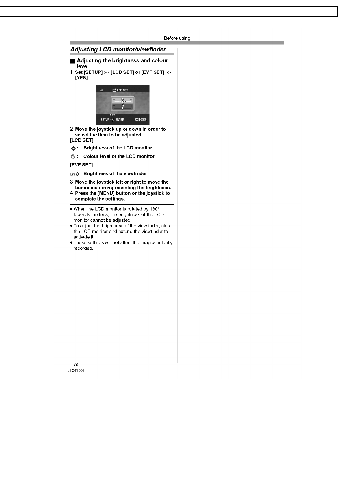
10.1. Cleaning Lens, Viewfinder and LCD Panel
10.2. How to use the DVC Head Cleaning Tape / VFK1451
11 Block Diagrams
12 Schematic Diagrams
12.1. SCHEMATIC DIAGRAM & CIRCUIT BOARD LAYOUT
NOTES
12.2. FRONT SCHEMATIC DIAGRAM
12.3. LCD BACKLIGHT SCHEMATIC DIAGRAM
12.4. EVF BACKLIGHT / CASSETTE COVER SCHEMATIC
DIAGRAMS
12.5. CCD / REAR / LCD SW / BATTERY CASE SCHEMATIC
DIAGRAMS
12.6. INTERCONNECTION SCHEMATIC DIAGRAM
12.7. VOLTAGE CHART
13 Printed Circuit Board
13.1. FRONT P.C.B.
13.2. LCD BACKLIGHT P.C.B.
14 Exploded Views
14.1. MAIN PARTS SECTION
14.2. FRONT AND BOTTOM CASE SECTION
14.3. SIDE CASE R AND LCD SECTION
14.4. CCD AND LENS SECTION
14.5. EVF SECTION
14.6. MECHANISM SECTION
14.7. PACKING PARTS AND ACCESSORIES SECTION
15 Replacement Parts Lists
15.1. MECHANICAL REPLACEMENT PARTS LIST
15.2. ELECTRICAL REPLACEMENT PARTS LIST
59
59
59
61
75
75
76
77
78
79
80
81
83
83
84
85
85
86
87
88
89
90
91
92
92
95
2

GS24EG NV-GS26GK / NV-GS27E NV-GS27E B / NV-GS27EE NV-GS27E F / NV-GS27EG NV-GS27E P / NV-GS27 GC NV-GS27GN / NV-GS37 E NV- GS37EB / NV-GS37 EG NV- GS37EK / NV- GS37EP NV-GS47EE
-GS47GC NV-GS57E E / NV-GS57GC NV-GS58GK
1 Safety Precautions
1.1. General Guidelines
1. IMPORTANT SAFETY NOTICE
There are special components used in this equipment
which are important for safety. These parts are marked by
in the Schematic Diagrams, Circuit Board Layout,
Exploded Views and Replacement Parts List. It is essential
that these critical parts should be replaced with
manufacturer’s specified parts to prevent shock, fire, or
other hazards. Do not modify the original design without
permission of manufacturer.
2. An Isolation Transf ormer should always be used during the
servicing of AC Adaptor whose chassis is not isolated from
the AC power line. Use a transformer of adequate power
rating as this protects the technician from accidents
resulting in personal injury from electrical shocks. It will also
protect AC Adaptor from being damaged by accidental
shorting that may occur during servicing.
3. When servicing, observe the original lead dress. If a short
circuit is found, replace all parts which have been
overheated or damaged by the short circuit.
4. After servicing, see to it that all the protective devices such
as insulation barriers, insulation papers shields are properly
installed.
5. After servicing, make the following leakage current checks
to prevent the customer from being exposed to shock
hazards.
3

NV-GS24EG NV-GS26G K / NV-GS27E NV-GS27E B / NV-GS27EE NV-GS27E F / NV-GS27E G NV-GS27E P / NV-GS27 GC NV- GS27GN / NV-GS37 E NV-GS37EB / NV-GS37EG NV-GS37EK / NV- GS37EP NV-GS4
7
/ NV-GS47G C NV-G S57EE / NV-GS57G C NV-GS58 GK
2 Warning
2.1. Prevention of Electro Static Discharge (ESD) to Electrostatically
Sensitive (ES) Devices
Some semiconductor (solid state) devices can be damaged easily by static electricity. Such components commonly are called
Electrostatically Sensitive (ES) Devices. Examples of typical ES devices are integrated circuits and some field-effect transistors and
semiconductor "chip" components. The following techniques should be used to help reduce the incidence of component damage
caused by electro static discharge (ESD).
1. Immediately before handlin g any semiconductor component or semiconductor-equipped assembly, drain off any ESD on your
body by touching a known earth ground. Alternatively, obtain and wear a commercially available discharging ESD wrist strap,
which should be removed for potential shock reasons prior to applying power to the unit under test.
2. After removing an electrical assembly equipped with ES devices, place the assembly on a conductive surface such as
aluminum foil, to prevent electrostatic charge buildup or exposure of the assembly.
3. Use only a grounded-tip soldering iron to solder or unsolder ES devices.
4. Use only an antistatic solder removal device. Some solder removal devices not classified as "antistatic (ESD protected)" can
generate electrical charge sufficient to damage ES devices.
5. Do not use freon-propelled chemicals. These can generate electrical charges sufficient to damage ES devices.
6. Do not remove a replacement ES device from its protective package until immediately before you are ready to install it. (Most
replacement ES devices are packaged with leads electrically shorted together by conductive foam, aluminum foil or comparable
conductive material).
7. Immediately before removing the protective material from the leads of a replacement ES device, touch the protective material
to the chassis or circuit assembly into which the device will be installed.
CAUTION :
Be sure no power is applied to the chassis or circuit, and observe all other safety precautions.
8. Minimize bodily motions when handling unpackaged replacement ES devices. (Otherwise harmless motion such as the
brushing together of your clothes fabric or the lifting of your foot from a carpeted floor can generate static electricity (ESD)
sufficient to damage an ES device).
4
GS24EG NV-GS26GK / NV-GS27E NV-GS27E B / NV-GS27EE NV-GS27E F / NV-GS27EG NV-GS27E P / NV-GS27 GC NV-GS27 GN / NV-GS37 E NV- GS37EB / NV-GS37 EG NV- GS37EK / NV-GS37EP NV- GS47EE
-GS47GC NV-GS57E E / NV-GS57GC NV-GS58GK
2.2. Caution for AC Cord
(VJA0940 type)
2.2.1. Information for your safety
IMPORTANT
Your attention is drawn to the fact that recording of prerecorded tapes or discs or other published or broadcast
material may infringe copyright laws.
WARNING
To reduce the risk of fire or shock hazard, do not expose this
equipment to rain or moisture.
CAUTION
To reduce the risk of fire or shock hazard and annoyi ng
interference, use the recommended accessories only.
FOR YOUR SAFETY
DO NOT REMOVE THE OUTER COVER
To prevent electric shock, do not remove the cover. No user
serviceable parts inside. Refer servicing to qualified service
personnel.
2.2.2. Caution for AC Mains Lead
2.2.2.1. Important
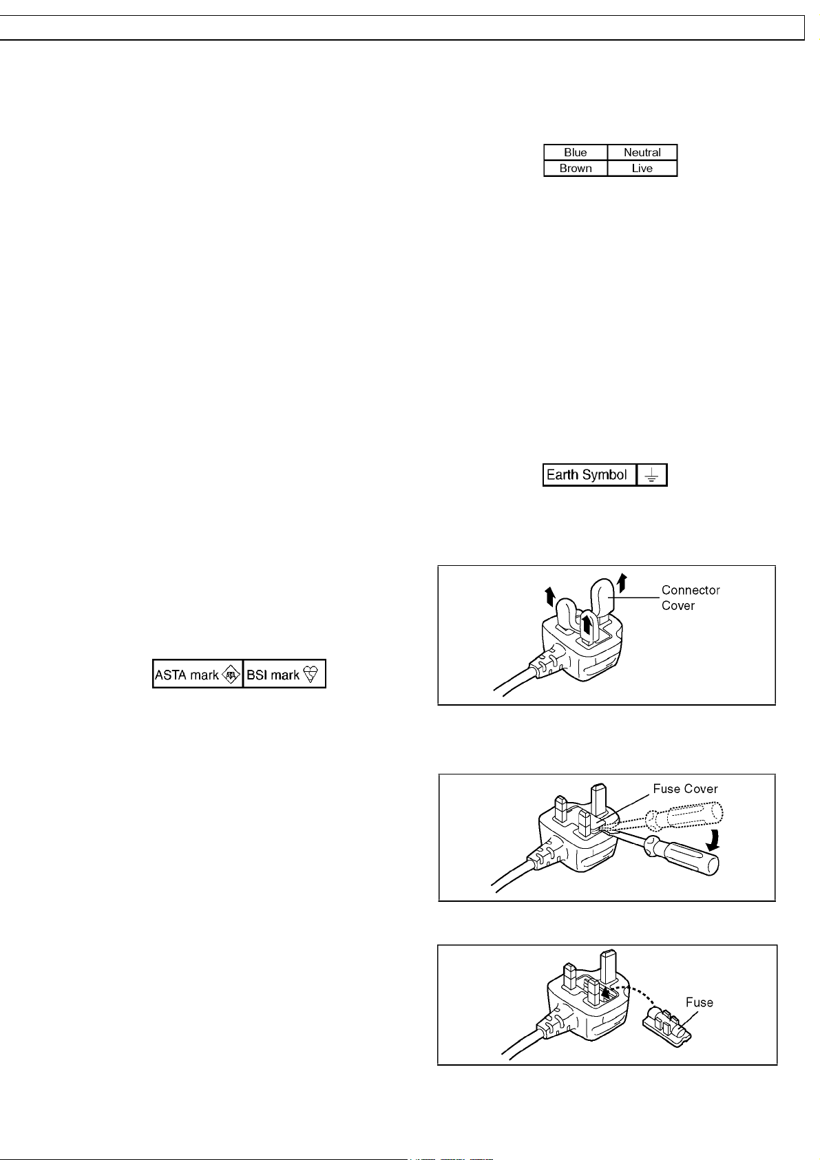
The wires in this mains lead are coloured in accordance with
the following code:
As the colours of the wires in the mains lead of this applian ce
may not correspond with the coloured markings identifying the
terminals in your plug, proceed as follows:
The wire which is coloured BLUE must be connected to the
terminal in the plug which is marked with the letter N or
coloured BLACK.
The wire which is coloured BROWN must be connected to the
terminal in the plug which is marked with the letter L or coloured
RED.
Under no circumstances should either of these wires be
connected to the earth terminal of the three pin plug, marked
with the letter E or the Earth Symbol.
For your safety, please read the following text carefully.
This appliance is supplie d with a moulded three-pin mains plug
for your safety and convenience.
A 5-ampere fuse is fitted in this plug.
Should the fuse need to be replaced please ensure that the
replacement fuse has a rating of 5 amperes and it is approved
by ASTA or BSI to BS1362.
Check for the ASRA mark or the BSI mark on the body of the
fuse.
If the plug contains a removable fuse cover you must ensure
that it is refitted when the fuse is replaced.
If you lose the fuse cover, the plug must not be used until a
replacement cover is obtained.
A replacement fuse cover can be purchased from your local
Panasonic Dealer.
If the fitted moulded plug is unsuitable for the socket outlet in
your home then the fuse should be removed and the plug cut
off and disposed of safety.
There is a danger of severe electrical shock if the cut off plug
is inserted into any 13-ampere socket.
If a new plug is to be fitted please observe the wiring code as
shown below.
If in any doubt, please consult a qualified electrician.
2.2.2.2. Before use
Remove the Connector Cover as follows.
2.2.2.3. How to replace the Fuse
1. Remove the Fuse Cover with a screwdriver.
2. Replace the fuse and attach the Fuse cover.
5
NV-GS24EG NV-GS26G K / NV-GS27E NV-GS27E B / NV-GS27EE NV-GS27E F / NV-GS27E G NV-GS27E P / NV-GS27 GC NV- GS27GN / NV-GS37 E NV-GS37EB / NV-GS37EG NV-GS37EK / NV- GS37EP NV-GS4
7
/ NV-GS47G C NV-G S57EE / NV-GS57G C NV-GS58 GK
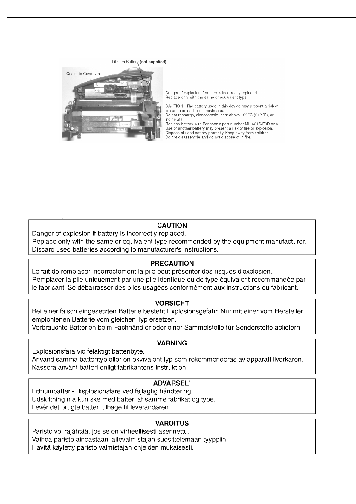
2.3. How to Replace the Lithium Battery
The lithium battery (ML-621S/F9D) is not supplied as a service part and must be replaced as part of the Cassette Cover Unit. (Refer
to "Disassembly and Assembly Instructions.")
NOTE:
This Lithium battery is a critical component. (Type No.: ML-621S/F9D Manufactured by Panasonic.) (Not supplied)
It must never be subjected to excessive heat or discharge.
It must therefore only be fitted in equipment designed specifically for its use.
Replacement batteries must be of the same type and manufacture.
They must be fitted in the same manner and location as the original battery, with the correct polarity contacts observed.
Do not attempt to re-charge the old battery or re-use it for any other purpose.
It should be disposed of in waste products destined for burial rather than incineration.
6

GS24EG NV-GS26GK / NV-GS27E NV-GS27E B / NV-GS27EE NV-GS27E F / NV-GS27EG NV-GS27E P / NV-GS27 GC NV-GS27 GN / NV-GS37 E NV- GS37EB / NV-GS37 EG NV- GS37EK / NV-GS37EP NV- GS47EE
-GS47GC NV-GS57E E / NV-GS57GC NV-GS58GK
3 Service Navigation
3.1. Introduction
This service manual contains technical information which will allow service personnel´s to understand and service this model.
Please place orders using the parts list and not the drawing reference numbers.
If the circuit is changed or modified, this information will be followed by supplement service manual to be filed with original service
manual.
Note 1:
1. VSK0561 is indicated on the AC Adaptor used in the following models:
NV-GS26GK and NV-GS58GK.
However, the AC Adaptor replacement part number is DE-974HA which should be used when ordering.
2. VSK0561 is indicated on AC Adaptor used in the following models:
NV-GS24EG, NV-GS27E, NV-GS27EB, NV-GS27EE, NV-GS27EF, NV-GS27EG, NV-GS27EP, NV-GS27GC, NVGS27GN, NV-GS37E, NV-GS37EB, NV-GS37EG, NV-GS37EK, NV-GS37EP, NV-GS47EE, NV-GS47GC, NV-GS57EE,
and NV-GS57GC.
However, the AC Adaptor replacement part number is DE-974GB which should be used when ordering.
Note 2:
1. This service manua l does not contain the following information, because of the impossibility of servicing at component level.
a. Schematic Diagram, Block Diagram and P.C.B. layout of Main P.C.B. and Camera P.C.B.
b. Parts List for individual parts of Main P.C.B. and Cemera P.C.B.
2. The following category are recycle module parts. Please send it to Central Repair Center.
a. *Main P.C.B. (LSEP8330P1/ LSEP8330Q1/ LSEP8330R1/ LSEP8330S1)
b. *Camera P.C.B. (LSEP8331P1/ LSEP8331Q1/ LSEP8331R1/ LSEP8331S1)
When a part replacement is required for repairing both Main P.C.B. and Camera P.C.B., replace the assembly parts.
3.2. About Lead Free Solder (PbF)
Distinction of PbF PCB:
PCBs (manufactured) using lead free solder will have a PbF stamp on the PCB.
Caution:
· Pb free solder has a higher melting point than standard solder; Typically the melting point is 50-70°F (30-40°C) higher.
Please use a high temperature soldering iron. In case of the soldering iron with temperature control, please set it to
700±20°F (370±10°C).
· Pb free solder will tend to splash when heated too high (about 1100°F/600°C).
When soldering or unsoldering, please completely remove all of the solder on the pins or solder area, and be sure to heat the
soldering points with the Pb free solder until it melts enough.
7
NV-GS24EG NV-GS26G K / NV-GS27E NV-GS27E B / NV-GS27EE NV-GS27E F / NV-GS27E G NV-GS27E P / NV-GS27 GC NV- GS27GN / NV-GS37 E NV-GS37EB / NV-GS37EG NV-GS37EK / NV- GS37EP NV-GS4
7
/ NV-GS47G C NV-G S57EE / NV-GS57G C NV-GS58 GK
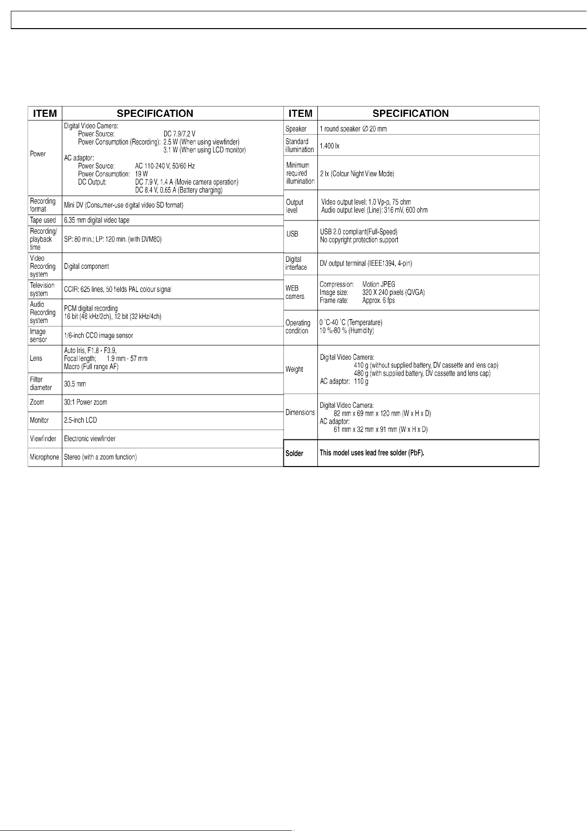
4 Specifications
8
GS24EG NV-GS26GK / NV-GS27E NV-GS27E B / NV-GS27EE NV-GS27E F / NV-GS27EG NV-GS27E P / NV-GS27 GC NV-GS27 GN / NV-GS37 E NV- GS37EB / NV-GS37 EG NV- GS37EK / NV-GS37EP NV- GS47EE
-GS47GC NV-GS57E E / NV-GS57GC NV-GS58GK
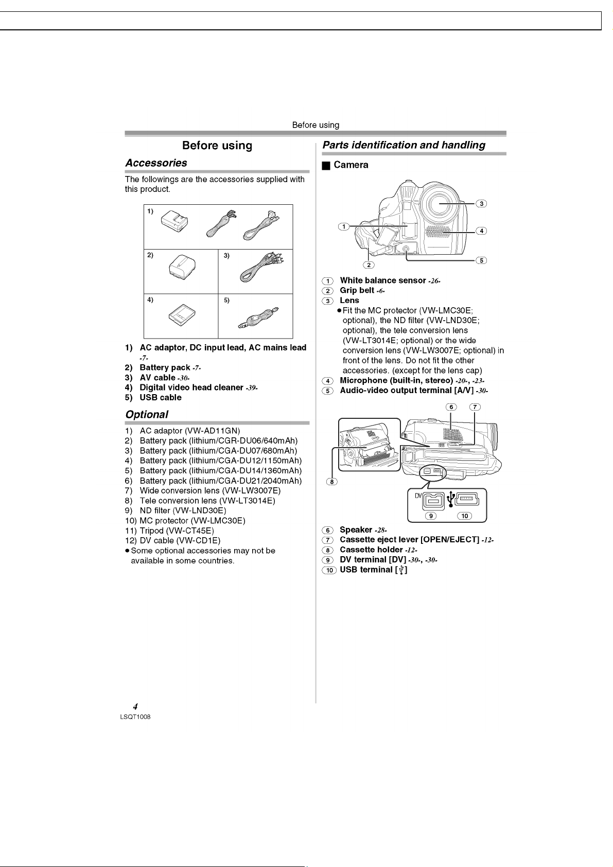
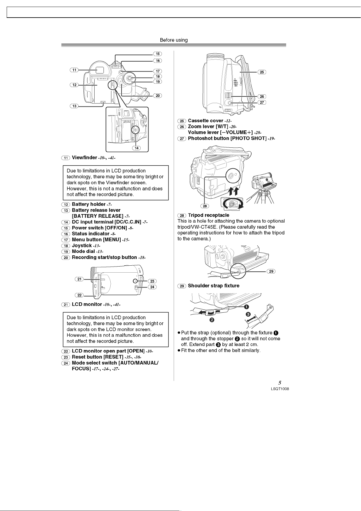
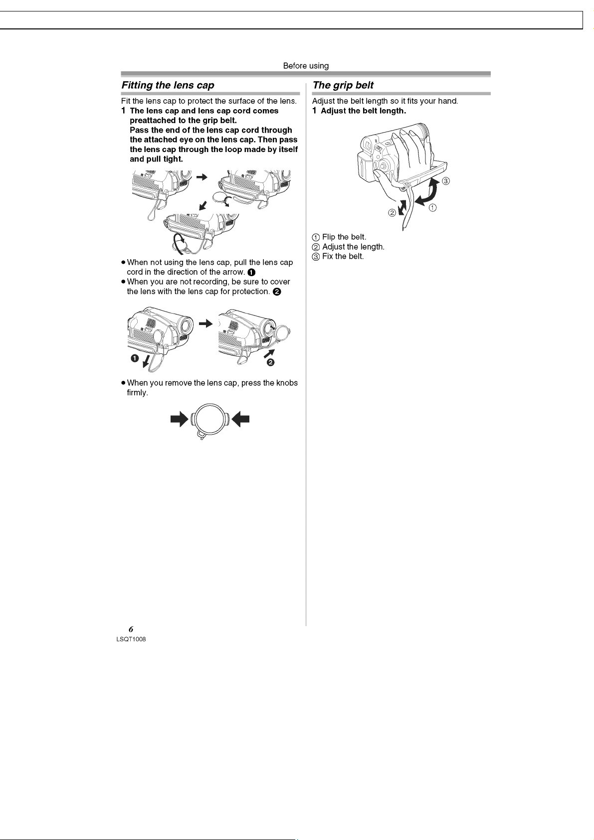
5 Location of Controls and Components
Followings are the Operation Guide for NV-GS27GN as a sample.
For other models, refer to each original Operation Guide.
9
NV-GS24EG NV-GS26G K / NV-GS27E NV-GS27E B / NV-GS27EE NV-GS27E F / NV-GS27E G NV-GS27E P / NV-GS27 GC NV- GS27GN / NV-GS37 E NV-GS37EB / NV-GS37EG NV-GS37EK / NV- GS37EP NV-GS4
7
/ NV-GS47G C NV-G S57EE / NV-GS57G C NV-GS58 GK
10
GS24EG NV-GS26GK / NV-GS27E NV-GS27E B / NV-GS27EE NV-GS27E F / NV-GS27EG NV-GS27E P / NV-GS27 GC NV-GS27 GN / NV-GS37 E NV- GS37EB / NV-GS37 EG NV- GS37EK / NV-GS37EP NV- GS47EE
-GS47GC NV-GS57E E / NV-GS57GC NV-GS58GK
11
NV-GS24EG NV-GS26G K / NV-GS27E NV-GS27E B / NV-GS27EE NV-GS27E F / NV-GS27E G NV-GS27E P / NV-GS27 GC NV- GS27GN / NV-GS37 E NV-GS37EB / NV-GS37EG NV-GS37EK / NV- GS37EP NV-GS4
7
/ NV-GS47G C NV-G S57EE / NV-GS57G C NV-GS58 GK
12
GS24EG NV-GS26GK / NV-GS27E NV-GS27E B / NV-GS27EE NV-GS27E F / NV-GS27EG NV-GS27E P / NV-GS27 GC NV-GS27 GN / NV-GS37 E NV- GS37EB / NV-GS37 EG NV- GS37EK / NV-GS37EP NV- GS47EE
-GS47GC NV-GS57E E / NV-GS57GC NV-GS58GK
13
NV-GS24EG NV-GS26G K / NV-GS27E NV-GS27E B / NV-GS27EE NV-GS27E F / NV-GS27E G NV-GS27E P / NV-GS27 GC NV- GS27GN / NV-GS37 E NV-GS37EB / NV-GS37EG NV-GS37EK / NV- GS37EP NV-GS4
7
/ NV-GS47G C NV-G S57EE / NV-GS57G C NV-GS58 GK
14
GS24EG NV-GS26GK / NV-GS27E NV-GS27E B / NV-GS27EE NV-GS27E F / NV-GS27EG NV-GS27E P / NV-GS27 GC NV-GS27 GN / NV-GS37 E NV- GS37EB / NV-GS37 EG NV- GS37EK / NV-GS37EP NV- GS47EE
-GS47GC NV-GS57E E / NV-GS57GC NV-GS58GK
15
NV-GS24EG NV-GS26G K / NV-GS27E NV-GS27E B / NV-GS27EE NV-GS27E F / NV-GS27E G NV-GS27E P / NV-GS27 GC NV- GS27GN / NV-GS37 E NV-GS37EB / NV-GS37EG NV-GS37EK / NV- GS37EP NV-GS4
7
/ NV-GS47G C NV-G S57EE / NV-GS57G C NV-GS58 GK
16
GS24EG NV-GS26GK / NV-GS27E NV-GS27E B / NV-GS27EE NV-GS27E F / NV-GS27EG NV-GS27E P / NV-GS27 GC NV-GS27 GN / NV-GS37 E NV- GS37EB / NV-GS37 EG NV- GS37EK / NV-GS37EP NV- GS47EE
-GS47GC NV-GS57E E / NV-GS57GC NV-GS58GK
17

NV-GS24EG NV-GS26G K / NV-GS27E NV-GS27E B / NV-GS27EE NV-GS27E F / NV-GS27E G NV-GS27E P / NV-GS27 GC NV- GS27GN / NV-GS37 E NV-GS37EB / NV-GS37EG NV-GS37EK / NV- GS37EP NV-GS4
7
/ NV-GS47G C NV-G S57EE / NV-GS57G C NV-GS58 GK
18
GS24EG NV-GS26GK / NV-GS27E NV-GS27E B / NV-GS27EE NV-GS27E F / NV-GS27EG NV-GS27E P / NV-GS27 GC NV-GS27 GN / NV-GS37 E NV- GS37EB / NV-GS37 EG NV- GS37EK / NV-GS37EP NV- GS47EE
-GS47GC NV-GS57E E / NV-GS57GC NV-GS58GK
19
NV-GS24EG NV-GS26G K / NV-GS27E NV-GS27E B / NV-GS27EE NV-GS27E F / NV-GS27E G NV-GS27E P / NV-GS27 GC NV- GS27GN / NV-GS37 E NV-GS37EB / NV-GS37EG NV-GS37EK / NV- GS37EP NV-GS4
7
/ NV-GS47G C NV-G S57EE / NV-GS57G C NV-GS58 GK
20
GS24EG NV-GS26GK / NV-GS27E NV-GS27E B / NV-GS27EE NV-GS27E F / NV-GS27EG NV-GS27E P / NV-GS27 GC NV-GS27 GN / NV-GS37 E NV- GS37EB / NV-GS37 EG NV- GS37EK / NV-GS37EP NV- GS47EE
-GS47GC NV-GS57E E / NV-GS57GC NV-GS58GK
21
NV-GS24EG NV-GS26G K / NV-GS27E NV-GS27E B / NV-GS27EE NV-GS27E F / NV-GS27E G NV-GS27E P / NV-GS27 GC NV- GS27GN / NV-GS37 E NV-GS37EB / NV-GS37EG NV-GS37EK / NV- GS37EP NV-GS4
7
/ NV-GS47G C NV-G S57EE / NV-GS57G C NV-GS58 GK
6 Service Mode
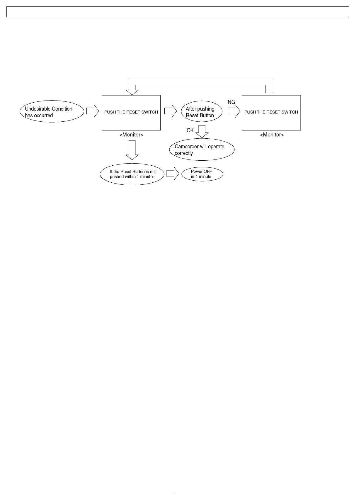
6.1. Error Display
"PUSH THE RESET SWITCH" is displayed automatically on the EVF or the LCD Monitor when an undesirable condition has
occurred.
Fig. 1
Note:
When "PUSH THE RESET SWITCH" is displayed repeatedly, service is required. Check the Error Code which is listed in the
Service Menu.
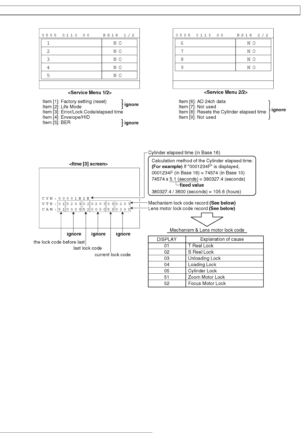
6.2. Service Menu
When abnormal detection contents are confirmed, do the following operation. Automatic diagnosis code will bedisplayed. (Service
Menu)
To enter the Service Menu
Push the [PHOTO SHOT], [JOYSTICK CONTROL LEFT] and [RECORDING START /STOP] simultaneously for 3 seconds (with
no SD Card inserted).
Note:
If a Disc or SD Card is inserted, the above operation will not work.
This operation displays the following Service Menu items.
To select the Item
1. Set to Service Menu.
2. Press the [JOYSTICK CONTROL UP/DOWN] to select item [3].
3. Press the [JOYSTICK CONTROL RIGHT] to display [YES/NO] screen.
4. Press the [JOYSTICK CONTROL UP/DOWN] to select [YES].
5. Press the [JOYSTICK CONTROL CENTER].
Note:
Only perform items 3 in the Service Menu.
To exit the Service Menu
Unplug the AC Cord.
22
GS24EG NV-GS26GK / NV-GS27E NV-GS27E B / NV-GS27EE NV-GS27E F / NV-GS27EG NV-GS27E P / NV-GS27 GC NV-GS27 GN / NV-GS37 E NV- GS37EB / NV-GS37 EG NV- GS37EK / NV-GS37EP NV- GS47EE
-GS47GC NV-GS57E E / NV-GS57GC NV-GS58GK
Fig. 2
23
NV-GS24EG NV-GS26G K / NV-GS27E NV-GS27E B / NV-GS27EE NV-GS27E F / NV-GS27E G NV-GS27E P / NV-GS27 GC NV- GS27GN / NV-GS37 E NV-GS37EB / NV-GS37EG NV-GS37EK / NV- GS37EP NV-GS4
7
/ NV-GS47G C NV-G S57EE / NV-GS57G C NV-GS58 GK
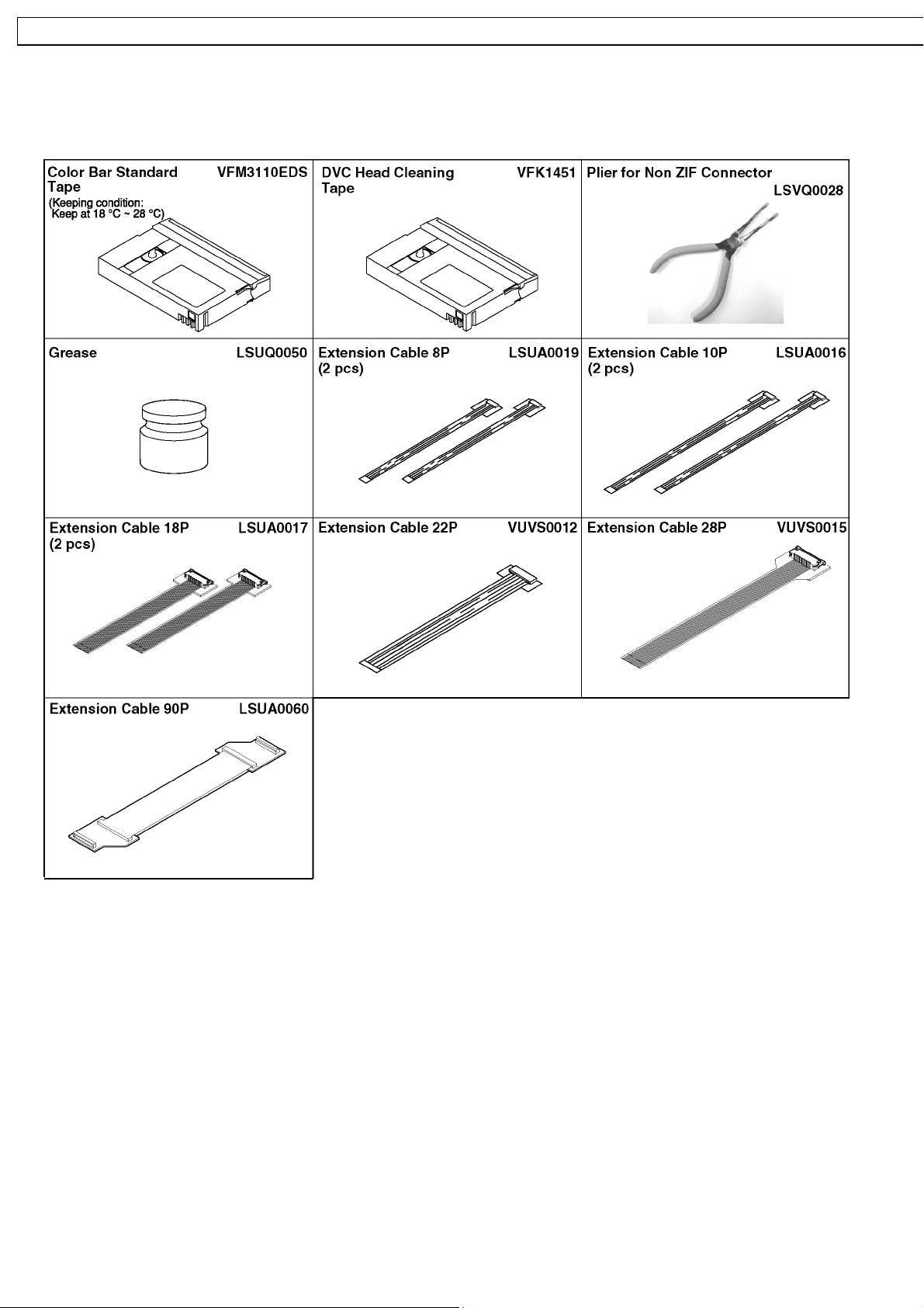
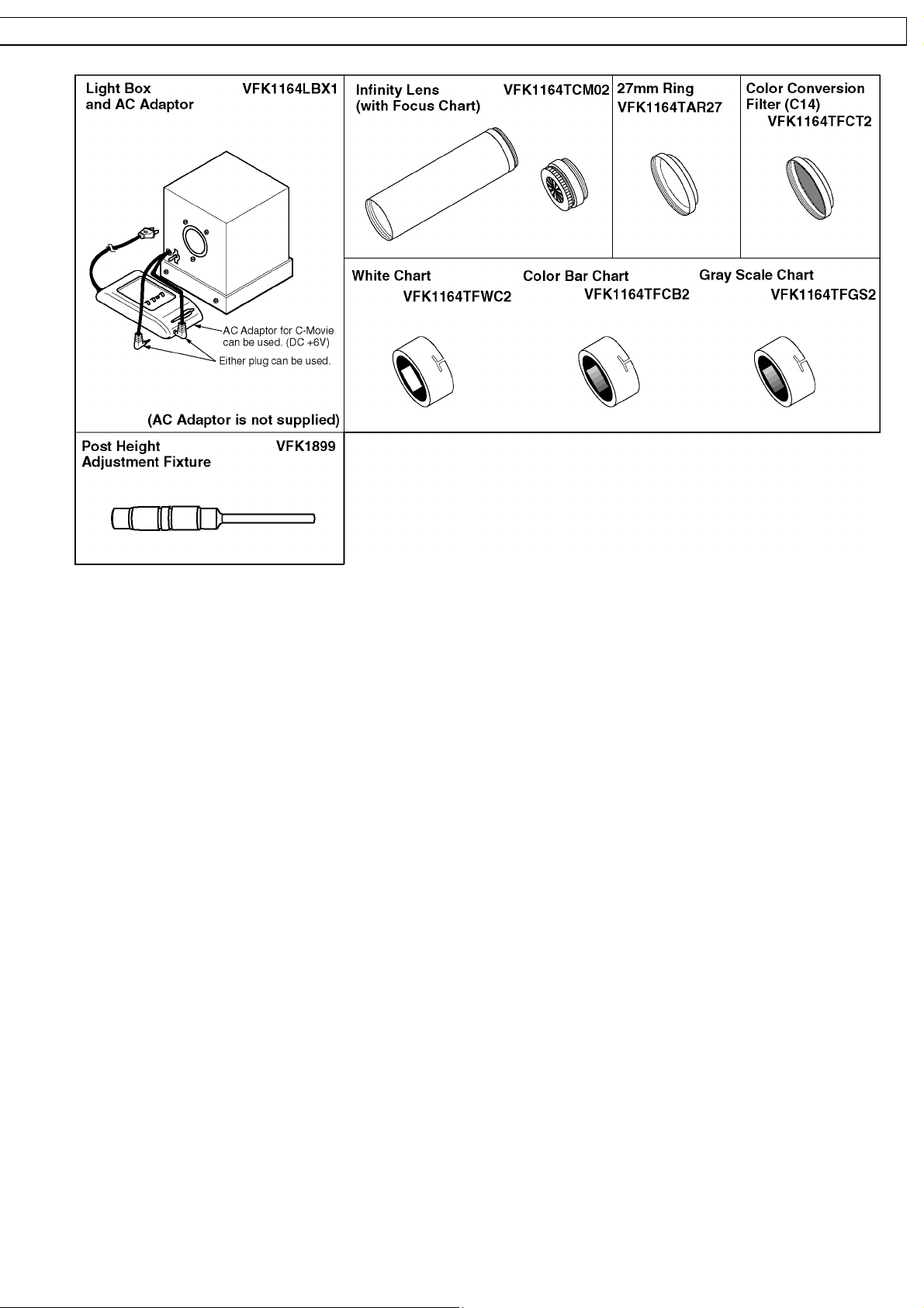
7 Service Fixture & Tools
7.1. Service Fixture and Tools
24
GS24EG NV-GS26GK / NV-GS27E NV-GS27E B / NV-GS27EE NV-GS27E F / NV-GS27EG NV-GS27E P / NV-GS27 GC NV-GS27 GN / NV-GS37 E NV- GS37EB / NV-GS37 EG NV- GS37EK / NV-GS37EP NV- GS47EE
-GS47GC NV-GS57E E / NV-GS57GC NV-GS58GK
25
NV-GS24EG NV-GS26G K / NV-GS27E NV-GS27E B / NV-GS27EE NV-GS27E F / NV-GS27E G NV-GS27E P / NV-GS27 GC NV- GS27GN / NV-GS37 E NV-GS37EB / NV-GS37EG NV-GS37EK / NV- GS37EP NV-GS4
7
/ NV-GS47G C NV-G S57EE / NV-GS57G C NV-GS58 GK
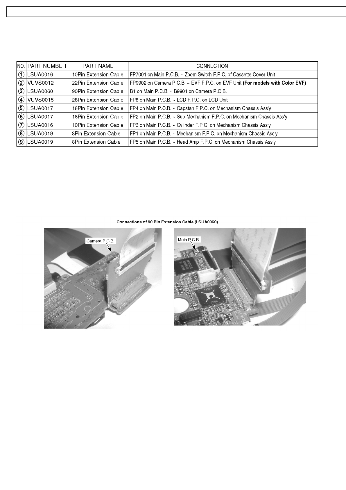
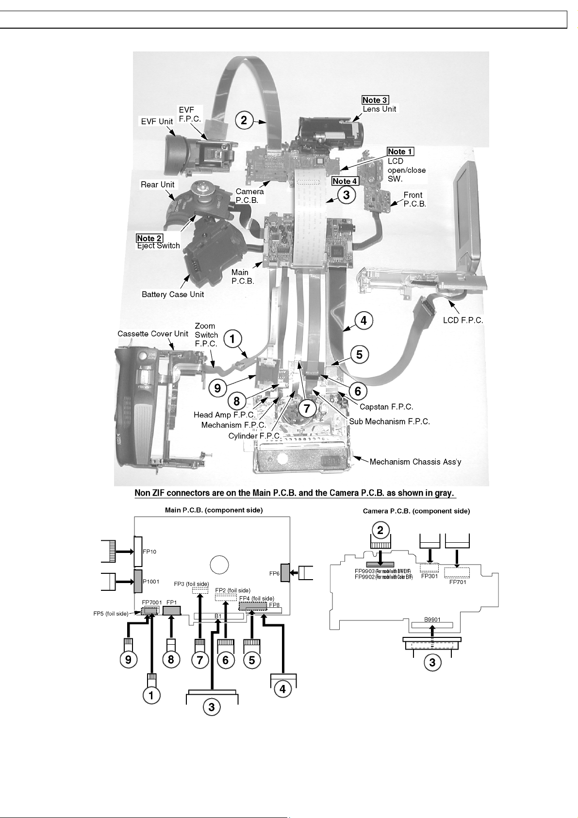
7.2. Service Position
7.2.1. Extension Cables for Service Position
Using the following Extension Cables , place the unit as shown for check and service.
Note:
1. The LCD open/close Switch is for changing between LCD Display and EVF Display. When turning on EVF Display, place some
paper or tape, etc. on LCD open/close Switch so that this Switch stays ON.
2. To eject the Mechanism, hold down the Eject Switch on the Rear Unit for a short time.
3. Use a grounded ESD wrist strap while disassembling the Lens portion.
4. Connect the F.P.C.s to the connectors, verifying the direction of F.P.C.s.
The Main P.C.B. or a Chip part will be especially damaged if the 90 Pin Extension Cable (LSUA0060) is misconnected.
5. Use extreme care when plugging or unplugging in connectors.
26
GS24EG NV-GS26GK / NV-GS27E NV-GS27E B / NV-GS27EE NV-GS27E F / NV-GS27EG NV-GS27E P / NV-GS27 GC NV-GS27 GN / NV-GS37 E NV- GS37EB / NV-GS37 EG NV- GS37EK / NV-GS37EP NV- GS47EE
-GS47GC NV-GS57E E / NV-GS57GC NV-GS58GK
Fig. 3
27
NV-GS24EG NV-GS26G K / NV-GS27E NV-GS27E B / NV-GS27EE NV-GS27E F / NV-GS27E G NV-GS27E P / NV-GS27 GC NV- GS27GN / NV-GS37 E NV-GS37EB / NV-GS37EG NV-GS37EK / NV- GS37EP NV-GS4
7
/ NV-GS47G C NV-G S57EE / NV-GS57G C NV-GS58 GK
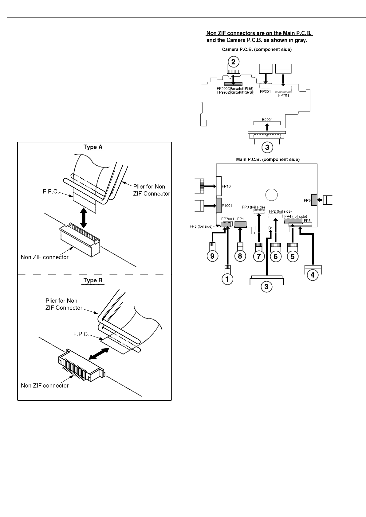
7.3. Removal/Installation of F.P.C.
From Non ZIF (Zero Insertion
Force) Connector
Removal/Installation of F.P.C. from the Non ZIF (Zero
Insertion Force) connector:
1. The Non ZIF connectors and the ZIF connectors are used
on the unit. And there are 2 types (Type A, Type B) of Non
ZIF connectors.
2. To remove the F.P.C. from the Non ZIF connector, use the
Plier for Non ZIF Connector (LSVQ0028) to pull out the
F.P.C. as shown. The same Plier for Non ZIF Connector
(LSVQ0028) should also be used to install the F.P.C. to the
Non ZIF Connector.
Fig. 4-1
3. Connect the F.P.C.s to the Non ZIF connectors, verifying
the direction of F.P.C as shown.
Fig. 4-2
28
GS24EG NV-GS26GK / NV-GS27E NV-GS27E B / NV-GS27EE NV-GS27E F / NV-GS27EG NV-GS27E P / NV-GS27 GC NV-GS27 GN / NV-GS37 E NV- GS37EB / NV-GS37 EG NV- GS37EK / NV-GS37EP NV- GS47EE
-GS47GC NV-GS57E E / NV-GS57GC NV-GS58GK
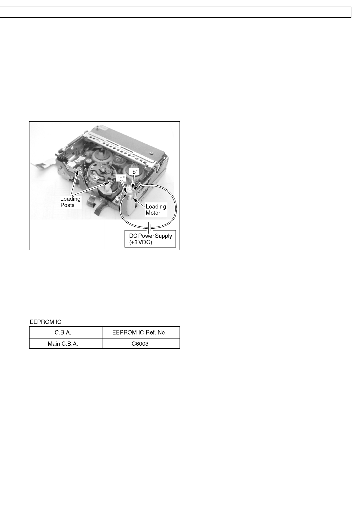
7.4. Method for Loading/Unloading
of Mechanism
CAUTION:
If loading does not start after DC Power Supply is applied ,
DO NOT continue to apply DC Power.
Apply +3 VDC Power Supply to the Loading Motor terminals.
Loading:
DC (-) to Portion "a," DC (+) to Portion "b"
Unloading:
DC (+) to Portion "a," DC (-) to Portion "b"
Fig. 5
7.5. EEPROM Data
CAUTION:
Be sure to save the EEPROM data using PC-EVR
Adjustment Program before service and adjustment in
order to make sure to avoid an accidental data loss, etc.
using PC-EVR Adjustment Program by first.
29

NV-GS24EG NV-GS26G K / NV-GS27E NV-GS27E B / NV-GS27EE NV-GS27E F / NV-GS27E G NV-GS27E P / NV-GS27 GC NV- GS27GN / NV-GS37 E NV-GS37EB / NV-GS37EG NV-GS37EK / NV- GS37EP NV-GS4
7
/ NV-GS47G C NV-G S57EE / NV-GS57G C NV-GS58 GK
7.6. Special Note
All integrated circuits and many other semiconductor devices
are electrostatically sensitive and therefore require the special
handlings techniques described under the
"ELECTROSTATICALLY SENSITIVE (ES) DEVICES" section
of this service manual.
30
 Loading...