

Panasonic NVG40 User Manual
Operating
Instructbns
$US HQ
PAL
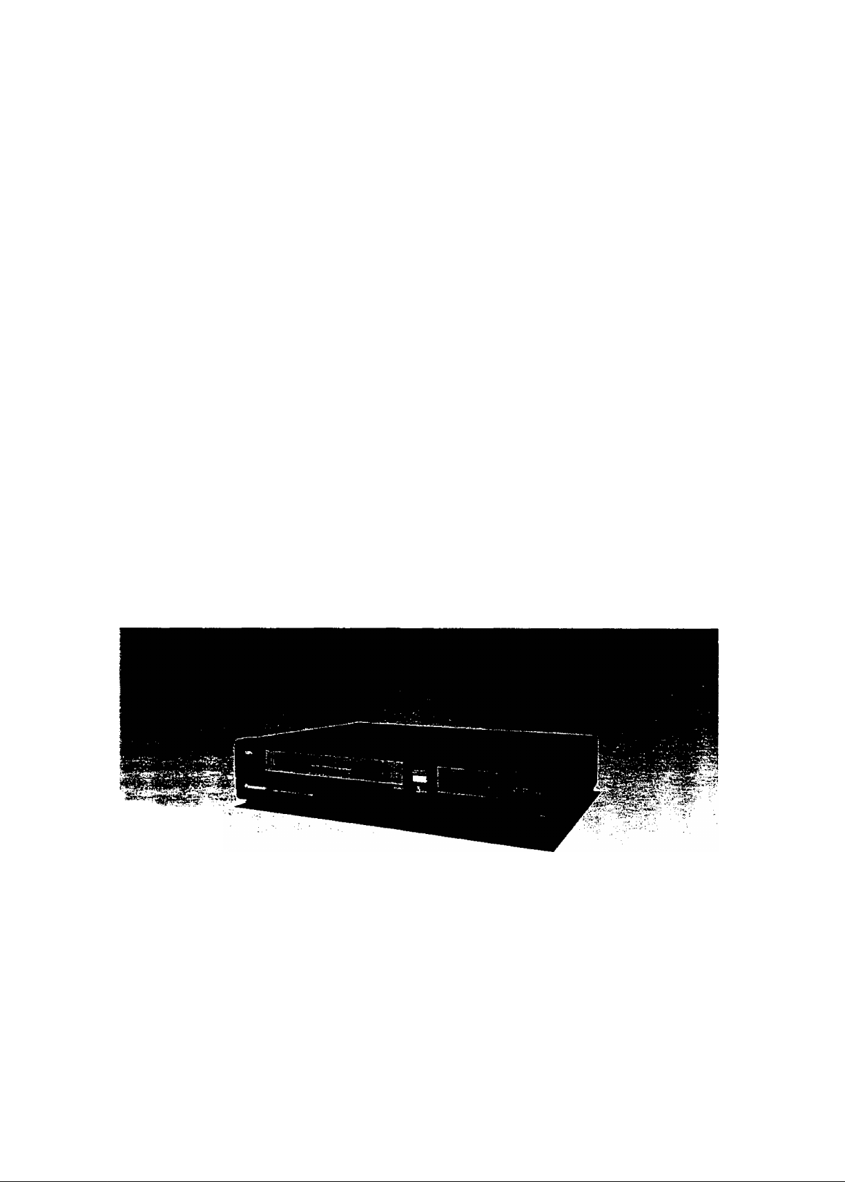
Video Cassette Recorder
NV-G40
Series
Panasonic
Before attempting to connect, operate or adjust this product, please read these instructions completely.
VQT2620

CONTENTS
Page
3 FEATURES
4 CONTROLS AND COMPONENTS
6 INFRA-RED REMOTE CONTROLLER AND DIGITAL
SCANNER
IMPORTANT
Your attention is drawn to the fact that
recording of pre-recorded tapes or discs
or other published or broadcast material
may infringe copyright laws.
8 INSTALLATION
8 TUNING THE TV SET TO THE VIDEO PLAYBACK
CHANNEL
9 SETTING THE CLOCK TO THE PRESENTTIME
1i) SETTING THE TUNER IN THE VTR
11 THE VIDEO CASSETTE
12 PLAYBACK
15 RECORDING FROM A TV BROADCAST SIGNAL
16 SUPER OTR FUNCTION
(ONE-TOUCH TIMER RECORDING)
18 TIMER RECORDING
22 CAMERA RECORDING
23 DUBBING (COPYING)
24 BEFORE REQUESTING SERVICE
WARNING
TO PREVENT FIRE OR SHOCK HAZARD,
DO NOT EXPOSE THIS EQUIPMENT TO
RAIN OR MOISTURE.
NV-G40A; Australian model
^ NV-G40EA: New Zealand model
n
i FOR YOUR SAFETY
■ DO NOT REMOVE OUTER COVER.
;■ To prevent electric shock, do not remove
cover. No user serviceable parts inside. Refer
servicing to qualified service personnel.
is the safety information.
26 CAUTIONS
27 SPECIFICATIONS
-9-

t
FEATURES
Slim Design and Front Loading System
This highly functional design allows loading the video
cassette from the front, thus minimizing the space required
for the placement.
Multi-Function Display
Whenever an operation button is pressed, the activated
function is immediately indicated on this easy-to-see
display. It shows you at a glance, in what operation mode
the VTR is functioning.
Super Still, Super Still Advance and Super Fine Slow Playback
Super Still, Super Still Advance and Super Fine Slow
Playback are possible with superb picture quality free from
noise and jitter.
Reception of up to 32 TV Stations
The built-in tuner in this VTR allows pre-tuning of as many
as 32 TV stations. So this VTR can accommodate virtually
any increase in available TV programmes in the future.
Infra-red Remote Controller
The Infra-red Remote Controller unit allows operation of
various functions from the comfort of your favorite viewing
position.
1-Month Calendar Timer
The clock/timer of the VTR is programmed with the
calendar up to the end of 2002, so it knows exactly what
day of the week it is on any given date. Programming of as
many as 4 timer recordings is possible up to one month in
advance.
Auto Operation
The extremely convenient Auto Operation functions of this
VTR include Auto Start and Auto Play when a recorded
cassette is inserted. Auto Eject which indicates that an
inserted cassette is not suitable for recording, VTR-Off
Eject for ejecting a cassette even with the VTR off, and Auto
Rewind at the end of a tape. If the VTR On/Off Switch is
pressed during the rewind mode including Auto Rewind, the
VTR will eject the cassette and turn itself off when
rewinding is completed.
Super OTR Function (One-Touch Timer Recording)
This convenient function makes it possible to easily
programme the VTR for recording of TV programmes with
immediate start or with start within 24 hours by precisely
setting the starting time and ending time to the desired
minute. When the recording ends, the VTR will automatical
ly turn itself off.
HQ (High Quality) Picture System
Lap Time Counter
The new Lap Time Counter is a great improvement over the
approximate counter systems of conventional VTRs. It
gives you an exact reading of the elapsed tape time in
hours, minutes and seconds, and makes it easy to calculate
the tape time left on a cassette.
Digital Scanner
This Digital Scanner makes it possible to programme timer
recordings by tracing the corresponding bar codes on the
supplied Programming Sheet. The traced programming
data can be confirmed on the built-in Bar Code Reader
Display before they are transmitted to the VTR at the push
of a button.
Video recorders carrying the HQ symbol mark feature the
new VHS High Quality Picture System. This system
assures complete compatibility with VTRs that use the
conventional VHS system.
-3-
CONTROLS AND COMPONENTS
FRONT
O O0Q O O O 0<D<D
la
/
® (D
No. Description
O Cassette Compartment
é ( Q 0 (D (!) C!) C) 0 0
Page
11
^ Clock Button 9
O Eject Button (A)
O Cassette-in Indicator
11
11
@ Infra-red Remote Control Receiver 6
atn1 1ir
1 r
rh
nr L.1 1 r~
1 nr
p
dDCbcp
:\
No. Description
0 Slow Tracking Control
0 Tuner Set-up Controls 10
0 Timer Controls
0 Timer Record Button
0 Rewind ◄◄/Review Q Button
Page
14
9
18
12
^ Channel Selection Up and Down Buttons 10
Q Multi-Function Display
Q OTR On Buttons 17
O OTR Off Buttons
16
(E) Clock/Counter Selector 12
5
0 Play Button (►)
0 Fast Forward ►►/Cue Q Button
0 Stop Button (■)
0 Pause/Still Button (II)
0 Record Button {•)
13
12
13
13
15
^ Memory/Search Lock Button 12 0 VTR/TV Selector 8
VTR On/Off Switch with Indicator
(E) Tracking Control
8
13
0 Reset Button 12
'4"
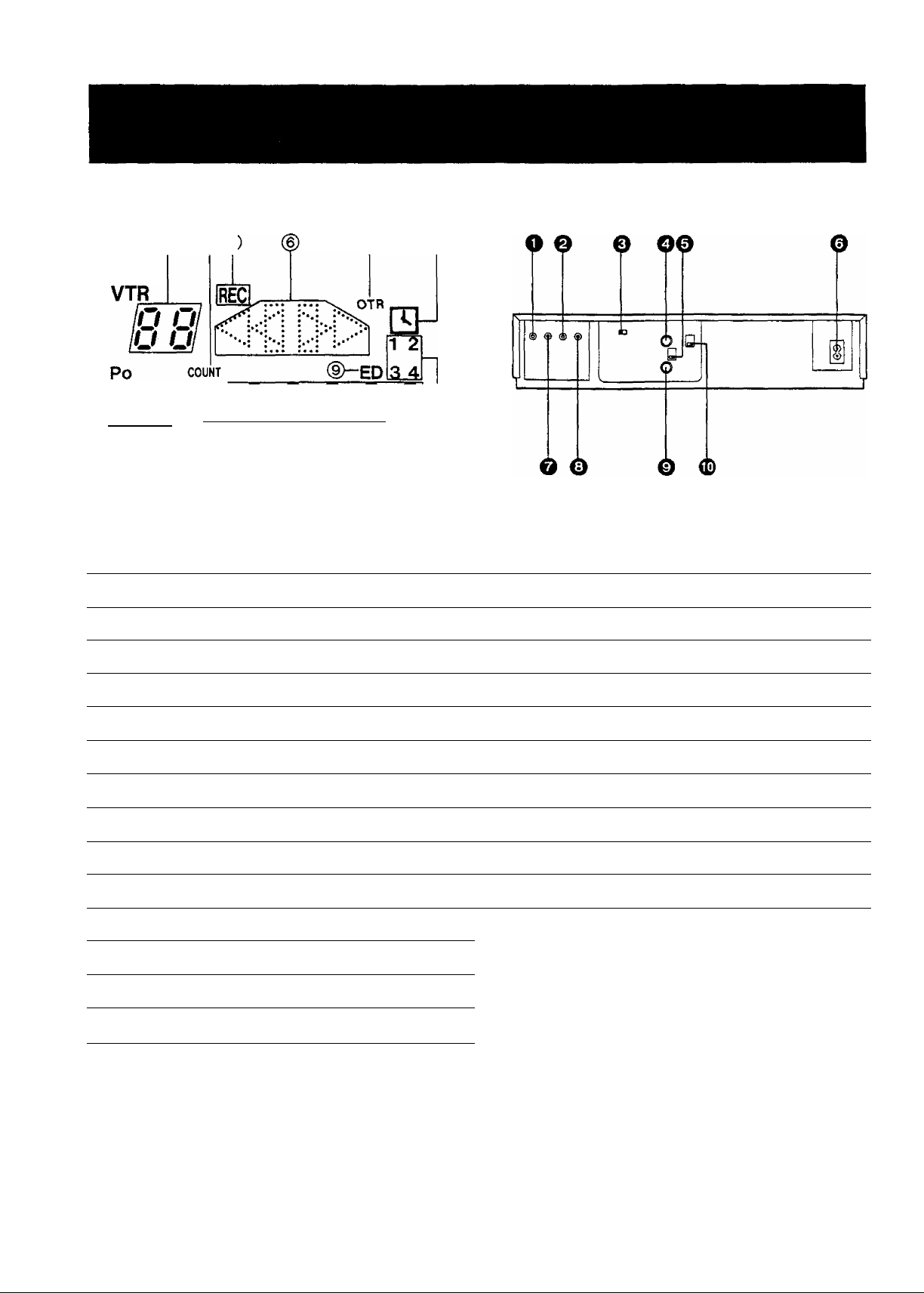
Multi-Function Display
REAR
® ® ® ®($
Id o
® ® ®
No. Description
(T) Position Indicator
@ VTR Indicator
@ Channel Display
S lOFF U • W • U. U. Ul
D//
© ®
QfS'Q Q Ql
>r / V
When dew forms:
Dew Indicator
Page
No. Description
10
8 ^ Audio Output Socket
10
0 Audio Input Socket
0 Test Signal Switch
Page
22
23
8
@ Tape Counter Mode Indicator 12
(5) Recording Indicator 15
@ Tape Running Display
@ OTR Indicator
(8) Timer Recording Indicator
Everyday Indicator
@ Date Display 9
(Jl) Memory Indicator
@ Search Lock Indicator 12
@ ClocWCounter Display 9
@ Timer Programme Number
12
16
18
19
12
18
0 RF Output Socket
0 RF Signal Level Switch
0 AC Mains Lead Socket
0 Video Input Socket
0 Video Output Socket
0 RF Input Socket
0 Video Playback Channel Selector
8
8
8
22
23
8
8
-5-
o

INFRA-RED REMOTE CONTROLLER AND DIGITAL SCANNER
Part Number: VEQ0684
'
.....
-........
&
0 VTR On/Off Button
0 Clock/Counter Selector
o
c
p
a
-------------
■o
■0
CZ] CB CZl
[=□
ooa
-©
o Record Buttons {•)
O Pause/Still Button (II)
0 Rewind ◄◄/Review Q Button
© Play Button (P-)
0 Slow Buttons
© Fast Forward P'P’/Cue @ Button
© Still Advance Button (ll^)
0 Stop Button (■)
0 Programme Position (Channel) Selector Buttons
0
VTR/TV Selector
r
(T) Transmit Button
Bar Code Reading Section
@ Digital Scanner On/Off Switch
@ Transmitting Section
How to Operate the Digital Scanner
Set the Digital Scanner On/Off Switch to ''ON".
•If no operation is performed for more than 25 seconds, the
scanner will automatically switch over to the power-saving
standby condition and the lamp wilt go off. (In this case, if
bar codes have already been read but not yet transmitted
to the VTR, the data will be cancelled.)
•When the Digital Scanner On/Off Switch is set to “ON"
but the lamp is not lit, set the switch to “OFF" and then to
“ON” again.
Tracing the Gar Codes
(§) Place the Digital Scanner vertically on the Small Box.
(§) Trace the bar code quickly in the direction of the arrow.
-6-
O
Cleaning Brush for the Digital Scanner
If the sensor in the tip of the Digital Scanner becomes
clogged with dirt, it may become impossible to read the bar
codes. Clean the tip from time to time with the supplied
brush as illustrated below.
Keep this brush in the storage case of the Digital Scanner.
'Cleaning Brush
•Move the brush several times over the
tip so that the hair enters the hole.
•Treat the Programming Sheet with care. If the sheet
gets dirty or scratched, the bar code reading may
become impossible.
•Protect the Digital Scanner from strong shocks and
vibration. Keep it away from water and places with
high temperature and humidity.
•If the bar code is traced slowly, it cannot be read
correctly.
•When there is no "Beep" sound, the reading of the
bar code is incomplete. Trace the bar code again.
•When using the Programming Sheet, put it on flat
surface. Reading the bar codes while holding it in
your hand or bending it, may result in incorrect
operation.
•Do not deviate from the bar code, nor stop tracing
halfway.
•Do not slant the scanner to trace the bar code.
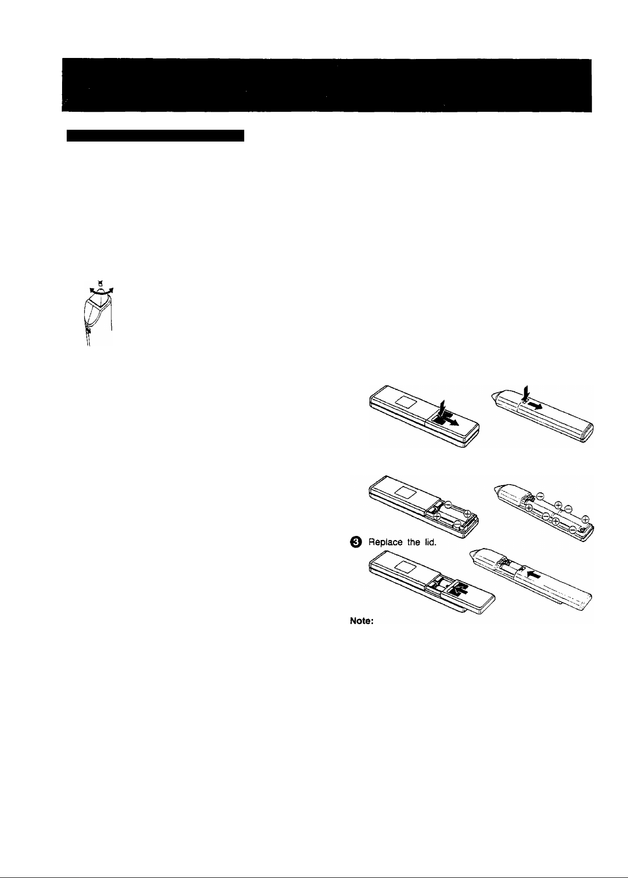
Power Source for the Remote Controller (Digital Scanner)
■ The Remote Controller is powered by two lEC “R6"
(Digital Scanner: 4 lEC ‘‘R03") size batteries. The life of
the batteries is about one year, however, it depends on
the frequency of use. Inspect and if necessary, replace
the batteries once a year.
CAUTION FOR BATTERY REPLACEMENT
•Load the new batteries with their polarities (0 and 0)
aligned correctly.
•Do not apply heat to batteries, or interna! short-circuit may
occur.
•If you do not intend to use the Remote Controller or Digital
Scanner for a long period of time, remove the batteries
and store them in a cool and dry place.
•Remove spent batteries immediately and dispose of them.
•Do not use an old and a new batteries together. (Also
never use an alkaline battery with a manganese battery.)
Load the batteries as follows:
O Remove the battery compartment lid.
© Place the batteries in the battery compartment as
indicated inside the battery compartment.
-7-
•The infra-red beam should be transmitted directly at the
Infra-red Remote Control Receiver on the front of the
VTR.
•Direct sunlight may interfere with the beam.
•The lightsensing angle of the Infra-red Remote Control
Receiver window In the VTR is about 60“.
•The unit should be used within a range of about 7 meters
from the front of the VTR.
Recommendation
To save battery power, make sure to set the Digital Scanner
On/Off Switch to "OFF" after using the Digital Scanner.
When the batteries are exhausted, the bar code reading
can no longer be performed.
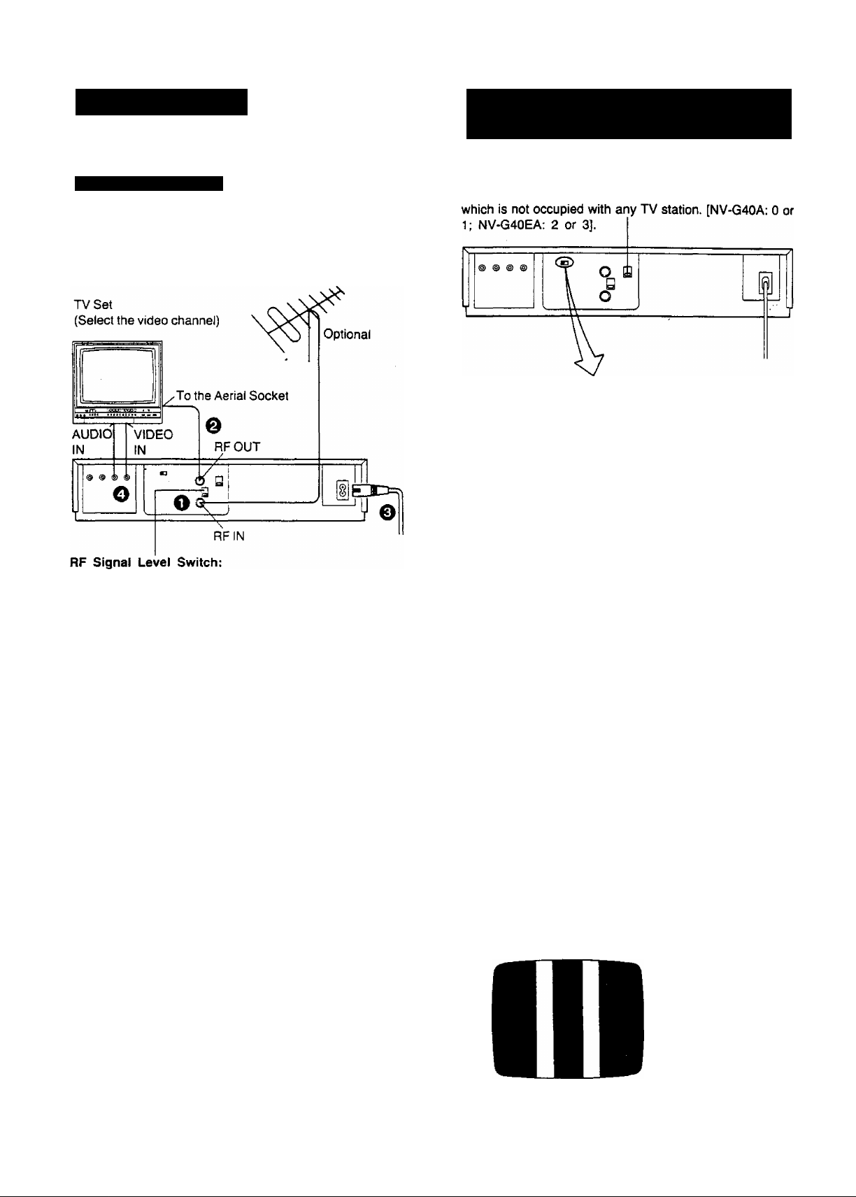
INSTALLATION
TUNING THE TV SET TO THE
VIDEO PLAYBACK CHANNEL
Connection to a TV Set
NV-G40A:
FOR YOUR SAFETY
Install ant external aerial to AS 1417.1.
Used to attenuate the reception of the VHF and/or UHF
aerial signals. If the reception is normal, set to “HIGH”. If
the signal is strong {stripes appear in the upper part of the
picture), set to “LOW”.
Video Playback Channel Selector [NV-G40A, EA}
This switch is used to select the Video Playback channel
OFF- I
ON
TEST
SIGNAL
o ©
Turn the TV set on and select the AV programme
position or another programme position that is not
occupied by any TV station.
Press the VTR On/Off Switch to turn the VTR On.
(FRONT SIDE)
VTR
O Connect the external aerial to the RF Input Socket of
the VTR.
0 Connect the aerial terminal on your TV set to the RF
Output Socket on the VTR with the supplied DIN-DIN
Coaxial Cable.
o Connect the AC Mains Lead to the AC Mains Socket of
the VTR to the mains outlet.
0 If the TV set is equipped with separate video and audio
input sockets, it is recommended to connect the VTR to
the TV set with separate video and audio cables.
•The corresponding indicator lights up.
0 Set the VTR/TV Selector to “VTR",
(FRONT PANEL)
VTR/TV
r~ I
•VTR Indicator will appear in the Multi-Function
Display.
Set the Test Signal Switch to “ON".
O
Tune the selected programme position (channel) of the
©
TV set to the VHF channel shown below for your
model. Confirm on the TV set that the received test
pattern is as shown below.
NV-G40A VHF channel 0 or 1‘
NV-G40EA VHF channel 2 or 3
*NV-G40A only
In some areas channel
0 may be used by local
TV station. In this case
switch to channel 1.
-8-
0 Set the Test Signal Switch to “OFF'. Your TV is now
ready to receive the RF output signal from the VTR.
0 To check, play back a pre-recorded tape and readjust
fine tuning of TV if nec^s^ry.
 Loading...