

Panasonic NV-G25 User Manual

Operating
Instructions
m HQ
Video Cassette Recorder
PAL
NV-G25 Series
S .r * *
n National
Before attempting to connect, operate or adjust this product, please read these instructions completely.

CONTENTS
Page
4 CONTROLS AND COMPONENTS
6 FEATURES
7 INSTALLATION, TUNING THE TV SET TO THE VIDEO PLAYBACK CHANNEL
8 SETTING THE CLOCK TO THE PRESENT TIME
10 SETTING THE TUNER IN THE VTR
11 THE VIDEO CASSETTE
12 PLAYBACK
15 SEARCH DIAL
16 RECORDING
17 SUPER OTR FUNCTION (ONE-TOUCH TIMER RECORDING)
19 TIMER RECORDING
22 CAMERA RECORDING
23 DUBBING (COPYING)
24 VHS INDEX SEARCH SYSTEM
25 INTRO SCAN FUNCTION
26 PROGRAMMABLE REMOTE CONTROLLER (INFRA-RED)
27 BEFORE REQUESTING SERVICE
29 CAUTIONS
30 SPECIFICATIONS

IMPORTANT
Your attention is drawn to the fact that
recording of pre-recorded tapes or discs or
other published or broadcast material may
infringe copyright laws.
WARNING
TO PREVENT FIRE OR SHOCK HAZARD,
DO NOT EXPOSE THIS EQUIPMENT TO
RAIN OR MOISTURE.
NV-G25A: Australian model
NV-G25EA: New Zealand model
lifi is the safety information.
FOR YOUR SAFETY
DO NOT REMOVE OUTER COVER.
To prevent electric shock, do not remove cover.
No user serviceable parts inside. Refer servicing
to qualified service personnel.
1
«11
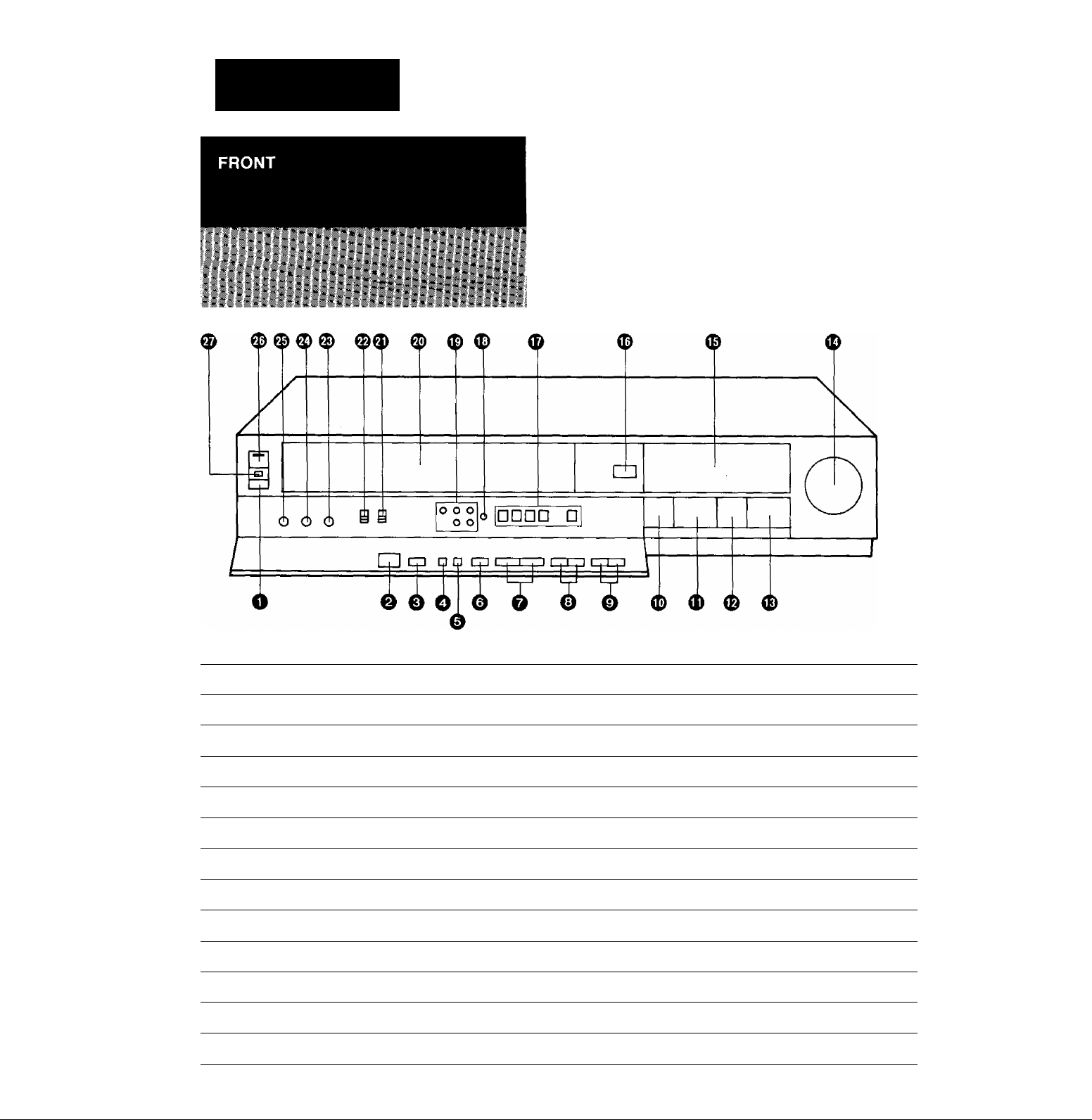
CONTROLS AND COMPONENTS
No. Description
O Eject Button (^)
^ Pause/Stilt Button (11)
O Pocord Button (•)
O Reset/Index Button
@ Memory/Search Button 12
© VTR/TV Selector
© Channel Selection Up and Down Buttons
O OTR On Buttons
© OTR Off Buttons
© Rewind ◄◄/Review @ Button
Page
11
13
12
10
No. Description
© Search Dial
© Multi-Function Display
16
7
18 © Tape Speed Selector
17
12 © Picture Sharpness Control
© Remote Control Receiver
© Timer Controls
© Clock Button 8
© Tuner Set-up Controls
© Cassette Compartment 11
© Edit Switch 23
o
Page
15
5
26
19
10
16
12
© Play Button (►)
© Fast Fonvard ►►/Cue © Button
© Stop Button (■)
12
12
14
© Slow Tracking Control
© Tracking Control 12
© VTR On/Off Switch with Indicator
Cassette-in Indicator
13
7
11
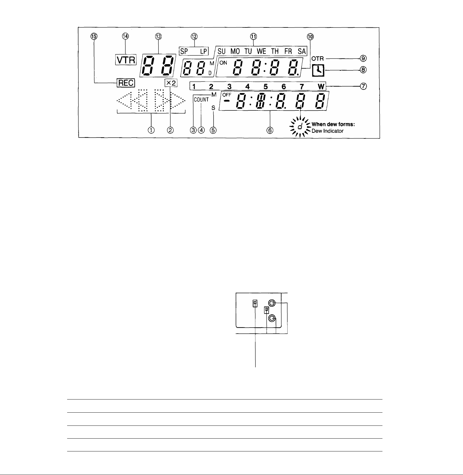
Multi Function Display
No.
(T) Tape Running Display
(3) Memory Indicator
@ Tape Counter Indicator
(5) Search Indicator
^1^ (7) Timer Programme Numbers
Description
Double Speed Indicator
Tape Counter Display
Timer Recording Indicator
REAR
@
Page
12
13
12
12
13
12
19
20
[m
No. Description
OTR Indicator
@ Clock Display
(Jl) Date Display
@ Tape Speed Indicator
@) Channel Display
@ VTR Indicator
Recording Indicator
Page
17
16
10
16
6
0 0OÒ ©
No. Description
O AC Mains Lead Socket 7 0 Video Output Socket 23
^ ^ Audio Input Socket
0 Video Input Socket 22
0 Audio Output Socket 23
messA Colour Mode/Test Signal Switch
Page
22
7 0 RF Output Socket
o o© ®
No. Description
0 Video Playback Channel Selector
0 RF Signal Level Switch
0 RF Input Socket
I
Page
7
7
7
7
FEATURES
Slim Design and Front Loading System
This htghiy functional design allows loading the video
cassette from the front, thus minimizing the space required
for the placement.
Multi-Function Display
Whenever an operation button is pressed, the activated
function is immediately indicated on this easy-to-see
display. It shows you at a glance, in what operation mode
the VTR is functioning.
Programmable Remote Controller (Infra-red)
In addition to letting you control all major VTR functions, this
handy Remote Controller also lets you programme timer
recordings from the comfort of your armchair.
Picture Sharpness Control
With this control, the contours of the playback picture can
be made sharper or softer.
8 hours recording and playback
The LP mode with a maximum recording and playback time
of 8 hours on a NV-E240 video cassette gives you double
savings in tape costs and storage space.
VMS Index Search System
With the Index Search function, up to 20 addresses (places
where an Index signal is recorded) can be skipped to
directly locate the beginning of the desired programme in
forward or reverse direction in the Fast Forward or Rewind
mode.
Intro Scan Function
The Intro Scan function plays back the first 10 seconds of
each programme (recorded with index signal) on a tape one
after another.
Super OTR Function (One-Touch Timer Recording)
This convenient function makes it possible to easily
programme the VTR for recording of TV programmes with
immediate start or with start within 24 hours by precisely
setting the starting time and ending time to the desired
minute. When the recording ends, the VTR will automati
cally turn itself off.
Auto Operation
The extremely convenient Auto Operation functions of this
VTR include Auto Start and Auto Play when a recorded
cassette is inserted, Auto Eject which indicates that an
inserted cassette is not suitable for recording, Power-Off
Eject for ejecting a cassette even with the VTR off, and Auto
Rewind at the end of a tape.
If the VTR On/Off switch is pressed during the rewind mode
including Auto Rewind, the VTR will eject the cassette and
turn itself off when rewinding is completed.
Reception of up to 16 TV Stations
The built-in tuner in this video recorder allows pretuning of
16 TV stations. So this VTR can accommodate virtually any
increase in available TV programmes in the future.
Super Stilt, Super Still Advance and Double Super
Fine Slow Playback
Super Still, Super Still Advance and Double Super Fine
Slow Playback are possible with superb picture quality free
from noise and jitter (SP mode only).
Digital Scanner
This Digital Scanner lets you programme timer recordings
by tracing the corresponding bar codes on the supplied
Programming Sheet and then transmitting the data to the
VTR.
Search Dial
The Search Dial allows immediate switching between any
of the playback functions of this VTR by simply turning this
control.
1-Month Calendar Timer
The clock/timer of the VTR is programmed with the
calendar up to the end of 2001, so it knows exactly what
day of the week it is on any given date. Programming of as
many as 8 timer recordings is possible up to one month in
advance.
HQ (High Quality) Picture System
Video recorders carrying the HQ symbol mark feature the
new VHS High Quality Picture System. This system
assures complete compatibility with VTRs that use the
conventional VHS system.
Lap Time Counter
The new Lap Time Counter is a great improvement over the
approximate counter systems of conventional VTRs. It
gives you an exact reading of the elapsed tape time in
hours, minutes and seconds, and makes it easy to calculate
the tape time left on a cassette.
INSTALLATION, TUNING
THE TV SET TO THE VIDEO
NV-G25A;
FOR YOUR SAFETY
Install any external aerial to AS 1417.1.
PLAYBACK CHANNEL
® ® @ ®
m
Q
O ©
1—1 T
COLOUR—I f
AUTO
------------
TEST—
Connection to a TV Set
0 Connect the external aerial to the RF Input Socket on
the VTR.
1
----------
-
COLOUR/
TEST SIGNAL
-Video Playback Channel Selector [NV-G25A, EA]
This switch is used to select the Video Playback channel
which is not occupied with any TV station. [NV-G25A: 0 or
1: NV-G25EA: 2 or 3].
RF Signal Level Switch:
Used to attenuate the reception of the VHF and/or UHF
aerial signals.
If the reception is normal, set to “HIGFt”. If the signal is
strong {stripes appear in the upper part of the picture), set
to “LOW".
0 Set the Colour Mode/Test Signal Switch to “TEST".
(REAR PANEL)
^11^ @ Connect the aerial terminal on your TV set to the RF
Output Socket on the VTR with the supplied DIN-DIN
Coaxial Cable.
0 Connect the AC Mains Lead (Supplied) to the AC
Mains Socket of the VTR, and a mains outlet.
Video Playback Channei
0 Turn the TV set on.
0 Press the VTR On/Off Switch to turn the VTR On.
(FRONT PANEL)
^ N
•The indicator will light up.
0
Set the VTR/TV Selector to “VTR”.
i
VTR
(FRONT PANEL)
VTRTTV
COLOUR
AUTO^
TEST
COLOUR/
TEST SIGNAL
0
Tune the selected programme position (channel) of the
TV set to the VHF channel shown below for your
model. Confirm on the TV set that the received test
pattern is as shown below.
NV-G25A VHF channel 0 or 1*
NV-G25EA VHF channel 2 or 3
NV-G25A only
*ln some areas chan
nel 0 may be used by
local TV station. In
this case switch to
channel 1.
0
Set the Colour Mode/Test Signal Switch to “AUTO".
Your TV is now ready to receive the RF output signal
from the VTR.
0 To check.
Playback pre-recorded tape.
\____________________
►VTR Indicator will appear in the Multi-Function Display.
J
•If, during recording or playback, the colour is not
satisfactory, it can be stabilized by setting Colour
Mode/Test Signal Switch to COLOUR.
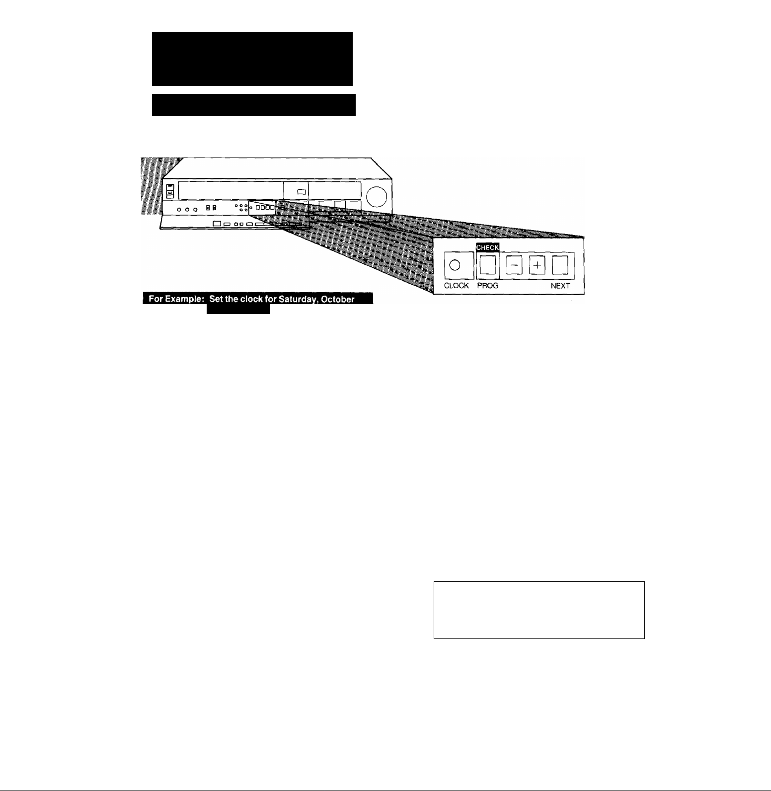
SETTING THE CLOCK TO THE PRESENT TIME
The built-in digital clock employs the 24-hour system.
8,1988,12:35.
•Connect the VTR to the mains outlet.
•Press the VTR On/Off Switch to turn the VTR On.
•The timer back-up system maintains the clock
operation for about 60 minutes in case of a power
failure. However, it takes more than 60 minutes for
the back-up circuit to become operational, after the
VTR is connected to the mains.
Note:
During date setting, the corresponding day is simuitaneously set.
O When connecting this VTR to the mains or after a long
power failure, both the date and time indications flash.
Z Q n n n ^
^ Press the Clock Button to start the date and time
setting.
TH
n • n
UU U
^ Press the (+) or (-) Button to set the year.
18 8z
n
U' u u
•
n
FR
n n
o
CLOCK
□ □
^ Press the (+) or (-) Button to set the month.
SA
n • n
uu u
0 Press the Next Button.
^ ^
-- I D U * U U next
J
0 Press the (H-) or (-) Button to set the date.
U
n n n
n> n n Q 0
uuu
_____________
n
□s
LJ
J
O Press the Next Button.
FR
n • n n
uu u
□
NEXT
0 Press the Next Button.
ncn n
^ UzU u
SA
□
NEXT

O
CLOCK
This Button is used to start and
finish the time setting.
O Press the (+) or (-) Button to set the hour.
SA
o n
U D L U
0 Press the Next Button.
□ 0
□
PROG
YEAR Mode
MONTH Mode[^
DATE Mode
Unnecessary for Time setting
1987^-1988.. .2000-*-2001-|
□
1987-»--20Q1 ■ ■ .1989-»-1988^
l-i-2^3...........10-i-l 1—12—I
t
___________________
1—12—11
0
t
____________________
JAN. MAR. MAY JUL. AUG. OCT.
DEC.
.......
0
1—2—3...29—30—31-
{
0
____________
1—31—30... 4—3—2-
APR.JUN.SEP. NOV.
0
1—2—3...29—30-
0
1—30—29
.......
□
4-Ì-3—2—
4—3—2-
\V i
t >?n nC
8
Press the (+) or (-) Button to set the minute.
8 I ^8 5^ SB
U 0 » L > J JjK,
_______________
0 Press the Clock Button when the present time be
comes exactly 12;35'00".
Q
O D
I I. u ^
____
?• D C
* r
t c • J
I * /SA
'ru<^
SA
□
NEXT
o
CLOCK
J
FEB.
0
1—2-^...27—28or 29k___________________
1—29 or 28-27...3—2-
0
t
___________________
HOUR Mode
0
0—1—2—3.. .21—22—23
t_________________
0—23—22
0
MINUTE Mode
0
00—01—02.......57—58—59-|
00—59—58—57.. .02—01 1
0
J
□
NEXT
YEAR—MONTH— DATE
HOUR — MINUTE
.......
3—2—1
1
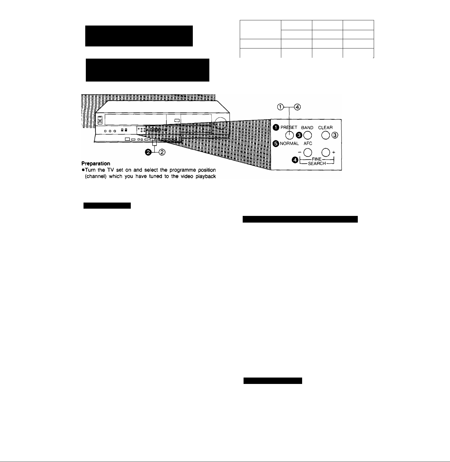
SETTING THE TUNER IN
THE VTR
The tuner in the VTR makes it possible to receive TV
broadcasts and to record these programmes without having
to turn on the TV set, The reception channels in the TV
bands shown on the right can be received
channel.
•Press the VTR On/Off Switch to turn the VTR on.
•Set the VTR/TV Selector to “VTR".
Tuning Procedure
O Press the Preset/Nornnal Button.
The indication on the Multi-Function Display changes
from the clock indication to the position indication.
© Press the Channel Up or Down Button to select a
programme position (channel) which you want to tune
to a TV station.
O Press the BAND/AFC Button to select the “1", “HI”,
or “U” position.
/" N
Display of the programme positions 1-16
0-5
1-3
The tuner in the VTR can be preset with up to 16 stations.
0 Press the Preset/Normal Button again.
The indication on the Multi-Function Display changes
to the clock indication.
Blanking of Unoccupied Programme Positions
5 A-11
4-11
21-69
21-69
(T) Press the Preset/Normal Button.
(2) Press the Channel Up or Down Button to select a
programme position (channel) which you do not want
to tune to a TV station.
@ Press the Clear Button (“--” will be displayed in the
Programme Position Indication).
I o ;
^6-1
Indication of the
selected TV band
O Press the Search (-<-) or (-) Button.
During the station search t
(The position indication *
flashes on and off.)
Tuned condition
•When the tuning of the station is completed, the
indication stops flashing and the tuned station is
automatically memorized.
•At every push of the SEARCH (-) or (-(-) Button, the
station will be tuned automatically.
Repeat steps 0~0 for each channel you want to tune to a
station.
Selection of the
programme position
I P O' /e
-^iMTTMrmrn^
b I
P o' !
b- I
J
P o
16
•Repeat steps (2) and (|) for any programme positions
on which no stations are to be tuned. Afterwards,
these programme positions will be skipped during
Up/Down selection of the programme position.
•To return a blanked station to the former (unblanked)
condition, select the corresponding programme
position on the VTR and press the CLEAR Button.
@ Press the Preset/Normal Button again.
Fine Tuning Procedure
If fine tuning is necessary, for example for a weak station
which is close to a strong station:
1. Make sure that the Preset/Normal Button is in the Off
condition, i.e. the Multi-Function Display shows the
present time.
2. Press the Fine Tuning or Button to obtain the
best tuning condition.
•To return the tuning to its former state, press the
BAND/AFC Button.
 Loading...