

Panasonic NV-G21 User Manual
Operating
Instructions
rr •• -T *
SBS HQ
Video Cassette Recorder
PAL
NV-G21 Series
. -I"«
_____
■ National
Before attempting to connect, operate or adjust this product, please read these instructions completely.

CONTENTS
Page
4 CONTROLS AND COMPONENTS
6 FEATURES
7 INSTALLATION, TUNING THE TV SET TO THE VIDEO PLAYBACK CHANNEL
8 SETTING THE CLOCK TO THE PRESENT TIME
10 SETTING THE TUNER IN THE VTR
11 THE VIDEO CASSETTE
12 PLAYBACK
15 RECORDING
16 SUPER OTR FUNCTION (ONE-TOUCH TIMER RECORDING)
18 TIMER RECORDING
21 CAMERA RECORDING
22 DUBBING (COPYING)
23 INFRA-RED REMOTE CONTROLLER
24 BEFORE REQUESTING SERVICE
26 CAUTIONS
27 SPECIFICATIONS
■ National
^Operating Instructions for
*the Digital Scanner
This Digital Scanner lets you progran^me timer recordings by
tracing the corresponding bar codes on the supplied Program
ming Sheet and then transmitting the data to the VTR.
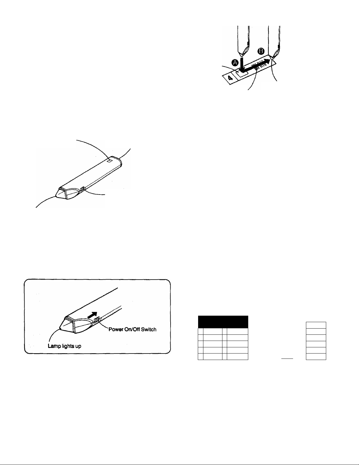
Names and Functions
Transmit Button
Press to transmit the
programming data
to the VTR.
Bar Code Reading Section
When the scanner is turned on, the red lamp will be lit.
Transmitting Section
The programmed data
is transmitted from
here to the VTR.
Power On/Off Switch
The “Beep”
sound indicates
that the barcode
Small Box
Trace the barcode
Bar Code
•It the bar code is traced slowly, it cannot be read
correctly.
•When there is no “Beep" sound, the reading of the bar
code is incomplete. Trace the bar code again.
•When using the Programming Sheet, put It on a flat
surface. Reading bent the bar codes or reading them
whilst holding them in your hand may cause incorrect
operation.
•Do not deviate from the bar code, nor stop tracing
halfway.
>Do not slant the scanner to trace the bar code.
completely past the last bar.
was read
completely.
Programming a Timer Recording
Example: When programming a timer recording for a pro
gramme that will be broadcast on channel position 4
on the 3rd of the month, from 7:00 to 7:30, trace the
bar codes in the order of the numbered arrows
shown below.
How to Operate the Digital Scanner
Before using the Digital Scanner, batteries must be inserted.
Turning the Digital Scanner On
Set Power On/Off Switch to “ON”.
•If no operation is performed for more than 25 seconds, the
scanner will automatically switch over to the power-saving
standby condition and the lamp will go off. (in this case, if bar
codes have already been read but not yet transmitted to the
VTR, the data will be cancelled.)
•When the Power On/Off Switch is set to “ON” but the lamp is
not lit, sot the switch to “OFF” and then to “ON” again.
^Tracing the Bar Codes
^ Place the Digital Scanner vertically on the Small Box.
© Trace the bar code quickly in the direction of the arrow.
O Trace the bar code for “CHANNEL".
o Trace the bar code for “DATE”.
0 Trace the bar code for “START TIME".
0 Trace the bar code for "END TIME”.
©CHANNEL 0®DATE >@STARTT1ME >®ÉHDTtME
I lia III) lilla nil I
DErrUBIË^
4 4
T
□ m\
6
□ III!
Î
□ m\\\
1
□ III!
•The "Bee Bee Bee Bee Beeeeep” sound signals that the
scanner is now ready for data transmission.
•When no sound is heard, read the bar codes once again.
•If more than one bar code is traced in the same group,
only the last tracing will be effective.
•The bar codes for the time from “0:00” (midnight) to
“4:59" in the morning are on the back of the Programming
Sheet.
•If the “CANCEL” bar code is read, all bar codes that have
been read so far will be cancelled.
T
T
7i
1
□ ill!
□ III!
□ nil
□ nil
□ III!
llilll
limi
limi
W
nilll
@ mill
n iiiii
iw-
@ limi
@ IIWII m ||■lll
@ limi
m mill
a mu
m
a
m
a
m
E
111
III
III!
nil
III!
J!!L
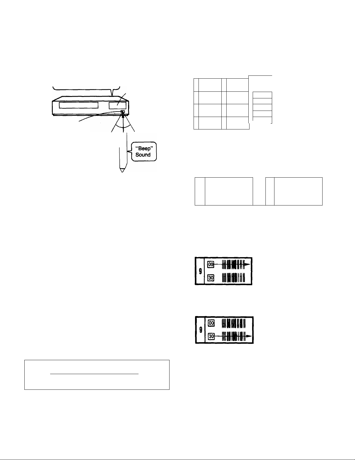
Keep pressing the Transmit Button and confirm that the
0
programmed data on the Multi-Function Display of the VTR
are as desired.
After releasing the button, the data will continue to be
displayed for about 12 seconds.
“Beep-beep-beep-beepbeep. .sound indicates
programming is completed.
Point the scanner at
the Infra-red Remote
Control Receiver Window
of the VTR and press
the Transmit Button,
Transmit Button
Transmission is possible from a
distance of up to 7 m from the VTR.
•If the transmission was not received correctly, the
“Beep-Beep, Beep-Beep" sound from the VTR will warn
you. In this case, perform transmission again.
•The transmission is possible when the VTR is turned on
but is not in any of the recording or playback operation
modes. It is also possible when the VTR is in the timer
recording standby mode (Q indication is tit).
•The programming will be done on the next lower unoccu
pied timer programme number (7~1).
If all programme numbers are occupied, the “Beep-Beep,
Beep-Beep" sound from the VTR will warn you that the
programming cannot be made.
•When the Transmit Button is pressed, the VTR will
automatically be put into the timer recording standby
condition and the VTR wilt be turned off.
•To operate the VTR before the timer recording will be
performed, press the Timer Rec. Button to suspend №e
timer recording standby condition. After using the VTR, be
sure to press the Timer Rec. Button again, otherwise the
timer recording will not be made.
[
For Programming Mora Than One Timer Recording in
Multi-Function
Display
Approx. 60°
^ucceealon
(Repeat the following operation steps (T)-®.
(T) Trace the "CANCEL” bar code on the Programming Sheet.
(—”
CANCEL
How to Trace the Bar Codes for Start and End Times
There are two kinds of time bar codes on the Programming
Sheet; time bar codes selectable in 30-minute steps and in
1-minute steps.
Time Bar Codes in
30-minute Steps
^ o®e^
m
limn
s
s
IIMIII
m
IIMIII
1
IS IIMIII
IS null
I
m
Miiii
m
limi
1
m
mill
(T) Setting the Time in 30-minute Steps
•Trace the appropriate bar code in the 30-minute-step
column only.
For example: when setting For example: when setting
B nmi
s
B
iniH
m
t
IS IIMIII
is
HIIIII
7
@
nini
m
1
m
to “9:00" to “9:30"
®HinmHiiih
9
Vs-
(g) Setting the Time in 1-minute Steps
@ imii
•When setting to a minute between 1 and 29, trace the
appropriate “-hMIN" bar code after tracing the bar
code.
For example: when setting to “9:12"
IIHIII
limi
inni
Si»-
31
32
33
»4
33
□ IMI
CD mi
m IMI
Q mi
[3 mi
iJil
'Time Bar Codes in
1-minute Steps
is IIMIII
9
n MIBtlF
42
This figure shows
the minute.
»When setting to a minute between 31 and 59, trace the
appropriate “+MIN” bar code after tracing the ^ bar
code.
For example: when setting to “9:42"
This figure shows
the minute.
/
42
d-m
•When a timer bar code with or minutes is traced
for the end time, the “Bee Bee Bee Bee Beeeeep” sound
which indicates reading completion is heard. When
subsequently tracing a "-i-MIN" bar code after tracing @
or to choose another minute setting, the reading
completion sound will be heard again.
© Trace the bar codes for “CHANNEL", “DATE”, “START
p TIME^' and "END TIME”.
© CcNifirm that the present time is displayed on the Multi-
Function Display of the VTR, and transmit the data.
•If the next timer programming data are transmitted while
the previous timer programming data are stiil being
the displayed timer recording data wilt be

For Everyday Recording
© Turn on the Digital Scanner and trace the "CHANNEL” bar
code.
To Confirm the Programme of a Timer Recording
To perform this operation, the VTR must be turned on or it must
be in the timer recording standby mode (Q indication is lit).
® Trace the "EVERYDAY" bar code.
r
----------
----EVERYDAY
1
______ ______ _ __
@ Trace the “START TIME” and then the "END TIME” bar
codes, and transmit the data to the VTR.
•Everyday recording will be performed from that day on.
•If a "DATE” bar code is traced after tracing the "EVERY
DAY” bar code, everyday recording will not be performed.
For Everyweek Recording
® Turn on the Digital Scanner and trace the “CHANNEL” bar
code.
© Trace the bar code for the desired day of the week among
the "EVERYWEEK” bar codes.
m
a
EVERYWEEK
Sunday MondayTuesday
Wednesday
Thursday —
Friday
-------------
□ II
□ II
□ II
Id lil 1
□ II
ID MI 1
© Trace the “CHECK” bar code.
\
—
-------
\
CHECK
1 U Tltlllli
V
j
_______
© Perform transmission.
•After releasing the Transmit Button, the programmed data
will be displayed for about 8 seconds (for about 25
seconds, if the Q indication is not tit) on the Multi-Function
Display.
•At every push of the Transmit Button, the timer program
me number advances to the next higher number.
To Cancel a Programmed Timer Recording
To perform this operation, the VTR must be turned on but not be
in any of the recording or playback operation modes, or it must
be in the timer recording standby mode (Q indication is lit).
To cancel a programmed timer recording, its data must be
displayed on the Multi-Function Display. If they are no longer
displayed, first, trace the "CHECK” bar code and perform
transmission (several times, if necessary, until the programme
you want to cancel is displayed).
Then, within 8 seconds (within 25 seconds, if the [3 indication is
not lit):
© Trace the "CANCEL” bar code.
© Perform transmission.
•To programme a new timer recording, perform the
programming from the beginning.
__
J
Saturday
@ Trace the "START TIME” and then the “END TIME” bar
codes, and transmit the data to the VTR.
•Everyweek recording will be performed from that week on.
•If a "DATE” bar code is traced after tracing the "EVERY
WEEK'' bar code, everyweek recording will not be
performed.
II
□
Cautions
•Treat the Programming Sheet with care. If the sheet gets
dirty or scratched, the bar code reading may become
impossible.
•Protect the Digital Scanner from strong shocks and
vibration. Keep it away from water and places with high
temperature and humidity.
I^Qwer Source for the Digital Scanner SpecifIcatlona
M The Digital Scanner is powered by 4 lEC “R03” size
batteries. The life of the batteries is about one year, however,
it depends on the frequency of use. Inspect and if necessary,
replace the batteries once a year.
CAUTION FOR BATTERY REPLACEMENT
«Load the new batteries with their polarities (0 and 0) aligned
correctly.
•Do not apply heat to batteries, or internal short-circuit may
occur.
•If you do not intend to use the Digital Scanner for a long period
of time, remove the batteries and store them in a cool and dry
place.
•Remove spent batteries immediately and dispose of them.
•Do not use old and new batteries together. (Also never use an
alkaline battery with a manganese battery.)
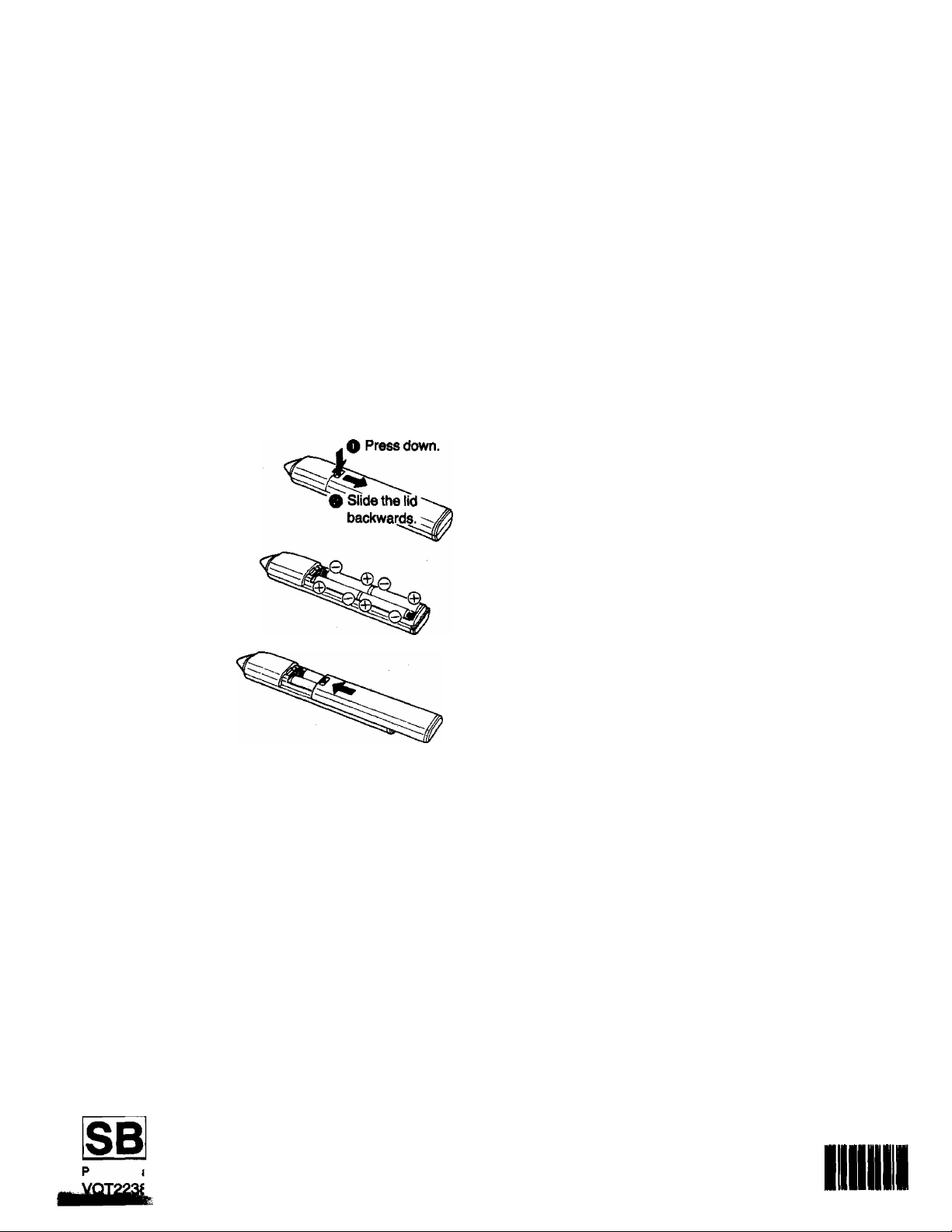
Load the batteries as follows:
O Remove the lid on the
rear of the scanner.
Load 4 lEC "R03” size
batteries as shown in the
illustration with their
polarities (0 and 0)
aligned correctly.
Power Source:
Dimensions:
Weight:
Accessories;
Weight and dimensions shown are approximate.
Specifications are subject to change without notice.
DC6V
20.5(W)x31 (H)x157(D)mm
Approx. 45 g (without batteries)
4 pcs. lEC “R03" size batteries
Programming Sheet
Replace the lid.
Ascommandation
To save battery power, make sure to set the Power On/Off
iSwiich to "OFF" after using the Digital Scanner. When the
paQpriee are exhausted, the bar code reading can no longer be
performed.
Matsushita Electric Trading Co., Ltd.
P.O. Box 286, Central Osaka, Japan
Printed in Japan
И
F0187T1027-10000 CD
II

IMPORTANT
Your attention is drawn to the fact that
recording of pre-recorded tapes or discs or
other published or broadcast material may
infringe copyright laws.
FOR YOUR SAFETY
WARNING
TO PREVENT FIRE OR SHOCK HAZARD,
bo NOT EXPOSE THIS EQUIPMENT TO
RAIN OR MOISTURE.
NV-G21A; Australian model
NV-G21EA: New Zealand model
rnmmmmMammmmMmmmmmM-mMBmMmmmMi
is the safety information.
DO NOT REMOVE OUTER COVER. f
To prevent electric shock, do not remove cover, li
No user serviceable parts inside. Refer servicing 'f
to qualified service personnel. fJ
„J
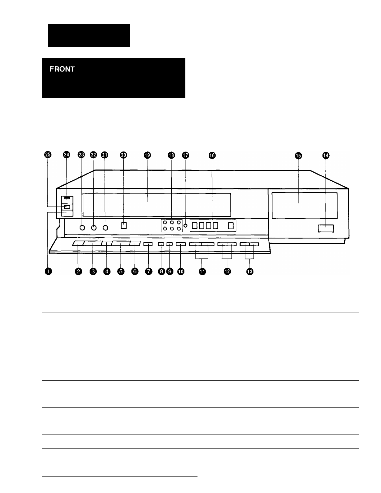
CONTROLS AND COMPONENTS
No. Description
• ^ «1. «
« * « # « »
Page
No. Description
o
Page
O Eject Button (^)
11
0 Rewind ◄◄/Review @ Button 12
0 Play Button (►)
0 Fast Forward ►►/Cue © Button
0 Stop Button (■)
0 Pause/Still Button (11)
0 Record Button (•)
0 Reset Button
0 Memory/Search Lock Button
12
12
14
13
15 0 Edit Switch
12
12 0 Slow Tracking Control
0 VTR/TV Selector
0 Channel Selection Up and Down Buttons 10
0 OTR On Buttons
0 OTR Off Buttons
17
16
0 Infra-red Remote Control Receiver Window
0 Multi Function Display
0 Timer Controls
0 Clock Button
0 Tuner Set-up Controls
23
5
8
8
10
0 Cassette Compartment 11
22
0 Picture Sharpness Control
7
0 Tracking Control
© VTR On/Off Switch with Indicator
0 Cassette-in Indicator
12
13
12
7
11
Multi Function Display
0 ®
VTR
U U O O M /ON Q Q . Q Q
U U O Od U U'U U.
SU MO TU WE TH FR SA
OTR-
He]
No. Description
(T) Tape Running Display
{§) Double Speed Indicator
@ Memory Indicator 12
(4) Tape Counter Indicator 12
(5) Search Lock Indicator
(6) Tape Counter Display
(7) Timer Programme Number
X2
COUNT
® ® ®
Page
12
13
13
12
18 0 Recording Indicator 15
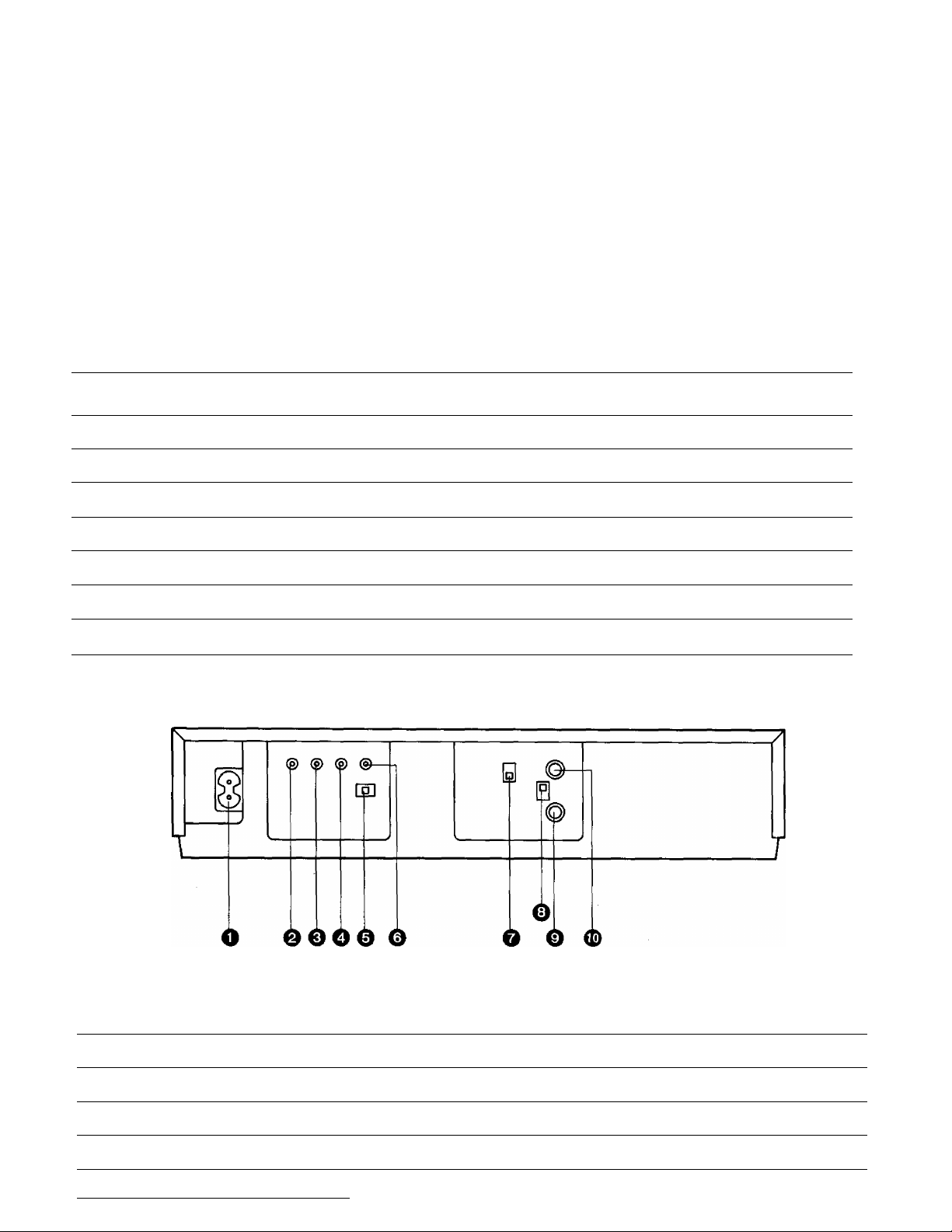
REAR
W
M
T O • © ' o o o
<Z)
u • m • u. u u
-t
^ ^ C- When dew forms:
° Dew Indicator
No. Description
(8) Timer Recording Indicator
(9) OTR Indicator
® Clock Display
0 Date Display 8
® Channel Display
® VTR Indicator
Page
19
16
8
10
7
No. Description
0 AC Mains Lead Socket
0 Audio Input Socket
0 Video Input Socket
0 Audio Output Socket
0 Colour Mode/Test Signal Switch
Page
7
21
21
22
7
No. Description Page
0 Video Output Socket
0 Video Playback Channel Selector
0 RF Signal Level Switch
0 RF Input Socket
0 RF Output Socket
22
7
7
7
7

FEATURES
; ~- --Tr/j*: -*'J
1 r r i
■S'* '*•»!. "'■'i.r
* •t. ^
Stim Design and Front Loading System
This highly functional design allows loading the video
cassette from the front, thus minimizing the space required
for the VTR.
Multi-Function Display
Whenever an operation button is pressed, the activated
function is immediately indicated on this easy-to-see
display. It shows you at a glance, in what operation mode
the VTR is functioning.
Infra-red Remote Controller
The Infra-red Remote Controller unit allows operation of
various functions from the comfort of your favourite viewing
position.
Picture Sharpness Control
With this control, the contours of the playback picture can
be made sharper or softer.
Super Still, Super Still Advance and Double Super
Fine Slow Playback
Super Still, Super Still Advance and Double Super Fine
Slow Playback are possible with superb picture quality with
minimum noise and jitter.
Super OTR Function (One-Touch Timer Recording)
This convenient function makes it possible to easily
programme the VTR for recording of TV programmes with
immediate start or with start within 24 hours and with the
starting time and ending time precisely to the minute, and
the VTR will automatically turn itself off when the recording
ends.
Digital Scanner
This Digital Scanner lets you programme timer recordings
by tracing the corresponding bar codes on the supplied
Programming Sheet and then transmitting the data to the
VTR.
Auto Operation
This VTR automatically turns itself “ON" when a video
cassette is inserted even if it was turned off. When the tab
of the inserted cassette is broken out, playback will start
automatically. Also, even if the VTR is off, when the Eject
Button is pressed, it automatically turns itself on to eject the
cassette tape and turns itself off again.
When a video cassette tape with a broken out tab is
inserted and the VTR is switched over to recording, OTR
and timer recording, the cassette tape will be automatically
ejected.
When the tape reaches its end (except during OTR and
timer recording), it will automatically rewind to the begin
ning.
If the VTR On/Off button is pressed during the rewind mode
including Auto Rewind, the VTR will eject the cassette and
turn itself off when rewinding is completed.
1-Month Calendar Timer
The clock/timer of the NV-G21 is programmed with the
calendar up to the end of 2001. Therefore it knows exactly
what day of the week it is on any given date. Programming
of as many as 8 timer recordings is possible up to one
month in advance.
Lap Time Counter
The new Lap Time Counter is a great improvement over the
approximate counter systems of conventional VTRs. It
gives you an exact reading of the elapsed tape time in
hours, minutes and seconds, and makes it easy to calculate
the tape time left on a cassette.
Reception of up to 16 TV Stations
The built-in tuner in this video recorder allows pretuning of
16 TV stations. So this VTR can accommodate virtually any
increase in available TV programmes in the future.
HQ (High Quality) Picture System
Video recorders carrying the HQ symbol mark feature the
new VHS High Quality Picture System. This system
assures complete compatibility with VTRs that use the
conventional VHS system.
 Loading...