

Page 1

VideQ Cassette 'Recorder
Gperaiing Instructions
VQT4572^
PALMTSe
Before attempting to connect, operate
. ■ or adjust,tois produci, please read '
thèse instructions completely:
Page 2

1 a aewng me i uner in tne V i h
15 Setting the Clock fo the Present Time
THIS EQUIPMENT TO RAIN OR
MOISTURE.
17 The Video Cassette
18 Auto Operation
19 Playback
24 Recording from a TV Broadcast Signal
25 Nicam System
26 Hi-Fi Audio System
27 Using the VTR as a Hi-Fi Audio Recorder
28 Super OTR Function(One-Touch Timer Recording)
30 Timer Recording
38 VHS Index Search System
39 Intro Scan Function
Time Search
40
41
Camera Recording
FOR YOUR SAFETY
a DO NOT REMOVE OUTER COVER.
To prevent electric shock, do not remove
cover. No user serviceable parts inside. Refer
servicing to qualified service personnel.
HO (High Quality) Picture System
Video recorders carrying the HQ symbol mark feature the
new VHS High Quality Picture System. This system
assures complete compatibility with VTRs that use the
conventional VHS system.
42 Dubbing (copying)
43 insert Editing
44
Audio Dubbing
45 Before Requesting Service
Page 3

Cautions
Please read these cautions before you operate this VTR.
Cassette Compartment Door
When first unpacking the unit, you may notice that the
cassette compartment door is partially open. This
condition is due to the operation of a safety device
designed to protect the unit from vibration during
shipment; it is not a malfunction. When the AC mains lead
is connected to a mains outlet, the door will return to its
original position.
Avoid Sudden Changes in Temperature
If the VTR is suddenly moved from a cold place to a warm
place, moisture may form on the tape and inside the VTR.
In this case, the Dew Indicator “ d " will flash on and off and
the VTR will not operate.
Humidity and Dust
Avoid places where there is high humidity or much dust,
which may cause damage to internal parts.
Do Not Obstruct the Ventilation Holes
The ventilation holes prevent abnormal increase in
temperature. Do not block or cover these holes. Especially
avoid covering the holes with soft materials such as cloth
or paper.
Keep away from High Temperature
Keep the VTR away from extreme direct heat such as
direct sunlight, heating radiators, or closed automobiles.
Keep Magnets away
Never bring a magnet or magnetized object near the VTR
because it will adversely affect the performance of the
VTR.
No Fingers or Other Objects Inside
Touching internal parts of this VTR is dangerous, and may
cause serious damage to the VTR, Do not attempt to
disassemble the VTR. There are no user serviceable parts
inside.
Video Head Clogging
The video heads place picture signals on the tape during
recording and read picture signals from the tape during
playback and they are, therefore, of critical importance for
the picture quality. To ensure that they can always provide
optimum picture quality, this VTR is equipped with an
Auto Head Cleaning Function that removes tape particles
and dust from the video heads. However, if the VTR is
used over extremely long periods of time, these heads
may still become dirty and clogged. In such a case, the
signals can no longer be recorded correctly, and the
playback picture will be distorted accordingly. This is the
case, for example, during the playback of a tape, the
sound is reproduced normally, but no picture is seen, or
the picture is greatly distorted. When such a symptom
case occurs have the recorder checked by qualified
service personnel.
If Dew Condensation Forms in the VTR
Condensation may form in the VTR if:
•The VTR is in a room where the heater has just been
turned on.
•The VTR is in a room with steam or high humidity.
•The VTR is brought from cold surroundings into a well-
heated room.
•The VTR is suddenly brought from cool surroundings,
such as an air-conditioned room or car, to a place which is
hot and humid.
When dew forms in the VTR: (Refer to page 6.)
The Dew Indicator “ d " on the Multi-Function Display will
flash on and off and all the function buttons are made nonoperational to protect the tape and the video heads. When
the Dew Indicator flashes, wait until this indicator
disappears.
• If dew condensation forms inside the VTR while the VTR
On/Off Switch is off, it will turn on automatically and the
Dew Indicator will flash on and off. As soon as the dew
condensation has been dissolved, the VTR will turn itself
off again.
Keep Water away
Keep the VTR away from flower vases, tubs, sinks, etc.
CAUTION: If liquids are spilled into the VTR, serious
damage could occur. If you spill any liquid into the VTR,
consult qualified service personnel.
Lightning
To avoid damage by lightning, disconnect the aerial plug
from the VTR.
Cleaning the VTR
Wipe the VTR with a dean, dry cloth. Never use cleaning
fluid, or other chemicals. And do not use compressed air
to remove dust.
Stacking
Place the VTR in a horizontal position, and do not place
■■ ling heavy on it.
Page 4
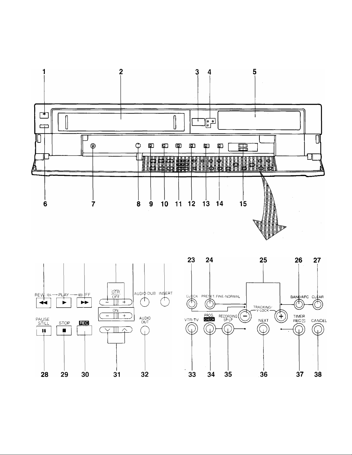
Controls and Components
FRONT
16 17 18
19 20 21 22
Page 5

Controls and Components (Cont’d)
No. Description Page No. Description Page
1 VTR On/Off Switch with Indicator 12
2 Cassette Compartment
3 Infra-red Remote Control Receiver
4 Audio Recording Mode Indicators
17
— 22 Insert Editing Button
25 23 Clock Button
5 Multi-Function Display
6 Eject Button {^)
7 Microphone Input Socket
8 Picture Sharpness Control
9 Hi-Fi/Normal Mix Switch
10 Nicam/Mono Switch
11 VTR System Selector
12 Noise Filter/Edit Selector
13 Tape Select Switch
17
44
19 27 Clear Button
43
25 29 Stop Button (■)
42
22
22
14 Remote Control Mode Select Switch 9
20 OTR On Buttons
21 Audio Dubbing Button
6
24 Preset/Fine/Normal Button
25 Tracking/V-Lock “ + ” and Buttons
26 Band/AFC Button
28 Pause/Still Button (11)
30 Record Button
31 Channel Selection Up and Down Buttons
32 Audio Output Mode Selector Button
33 VTR/TV Selector
28
44
43
15
13
13
13
14
19
19
24
13
26
11
15 Hi-Fi Rec Level Controls
16 Rewind ◄◄/Review @ Button
17 Play Button (►)
27
19
19
18 Fast Forward ►►/Cue @ Button 19
19 OTR Off Buttons
28
34 Programme/Check Button
35 Tape Speed Selector
36 Next Button
37 Timer Record Button
38 Cancel Button
30
24
15
30
31
Page 6
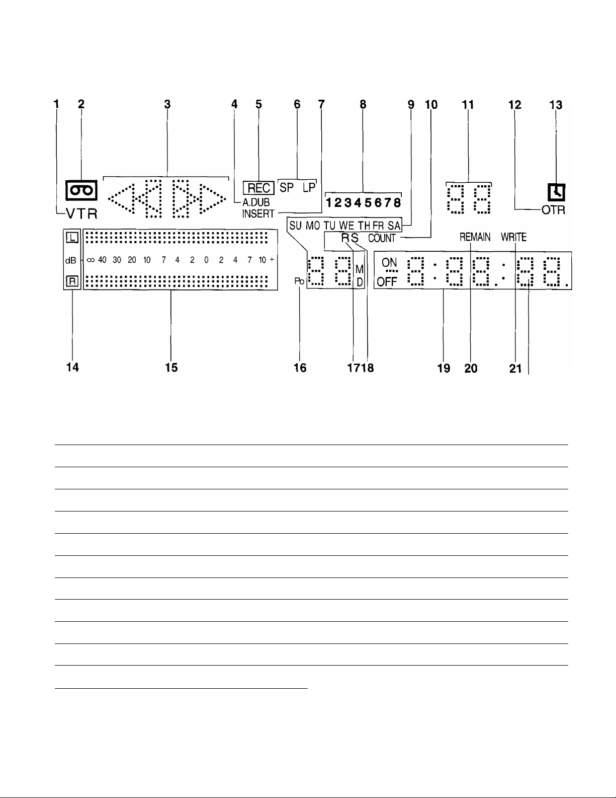
Controls and Components (Cont’d)
Multi-Function Display
No. Description
1 VTR Indicator
2 Cassette-in Indicator
3 Tape Running Display
4 Audio Dubbing Indicator
5 Recording Indicator
6 Tape Speed Indicator
7 Insert Editing Indicator
8 Timer Programme Number 30
9 Date Display
10 Counter Mode Indicator
11 Channel Display
When dew forms: ^ J v
Dew Indicator
Page
11
17
19 14 Audio Output Mode Indicators
44
24
24
43
15
21
13
No. Description
12 OTR Indicator
13 Timer Recording Indicator
15 Audio Level Meter
16 Position Indicator
17 Repeat Indicator 18
18 Search Indicator
19 Clock/Counter Indicator
20 Remaining Tape Time Indicator
21 Write Indicator 38
Page
28
30
26
26
13
38
15
23
Page 7
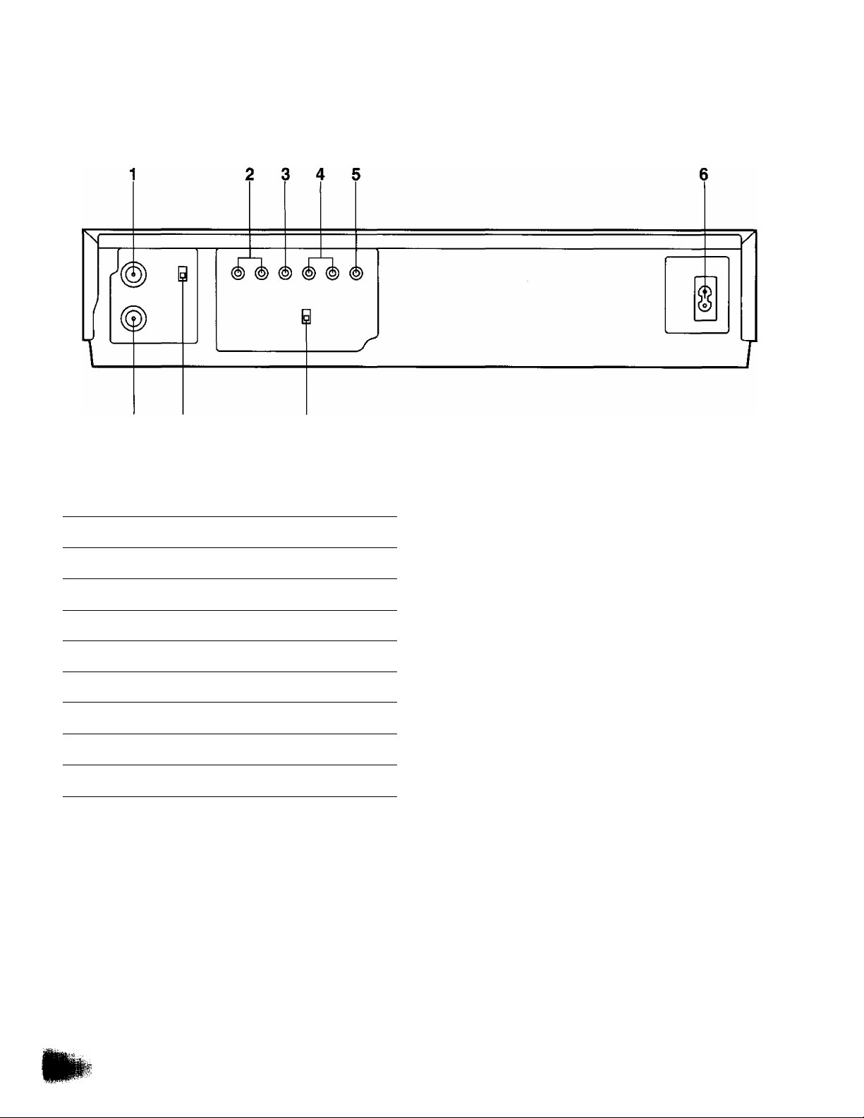
Controls and Components (ConVd)
REAR
7 8
No.
1 RF Output Socket
2 Audio Input Sockets
3 Video Input Socket
4 Audio Output Sockets
5 Video Output Socket
6 AC Mains Lead Socket
7 RF Input Socket
8 Video Playback Channel Selector
9 Test Signal Switch
Description Page
11
11
41
11
11
11
11
12
12
Page 8
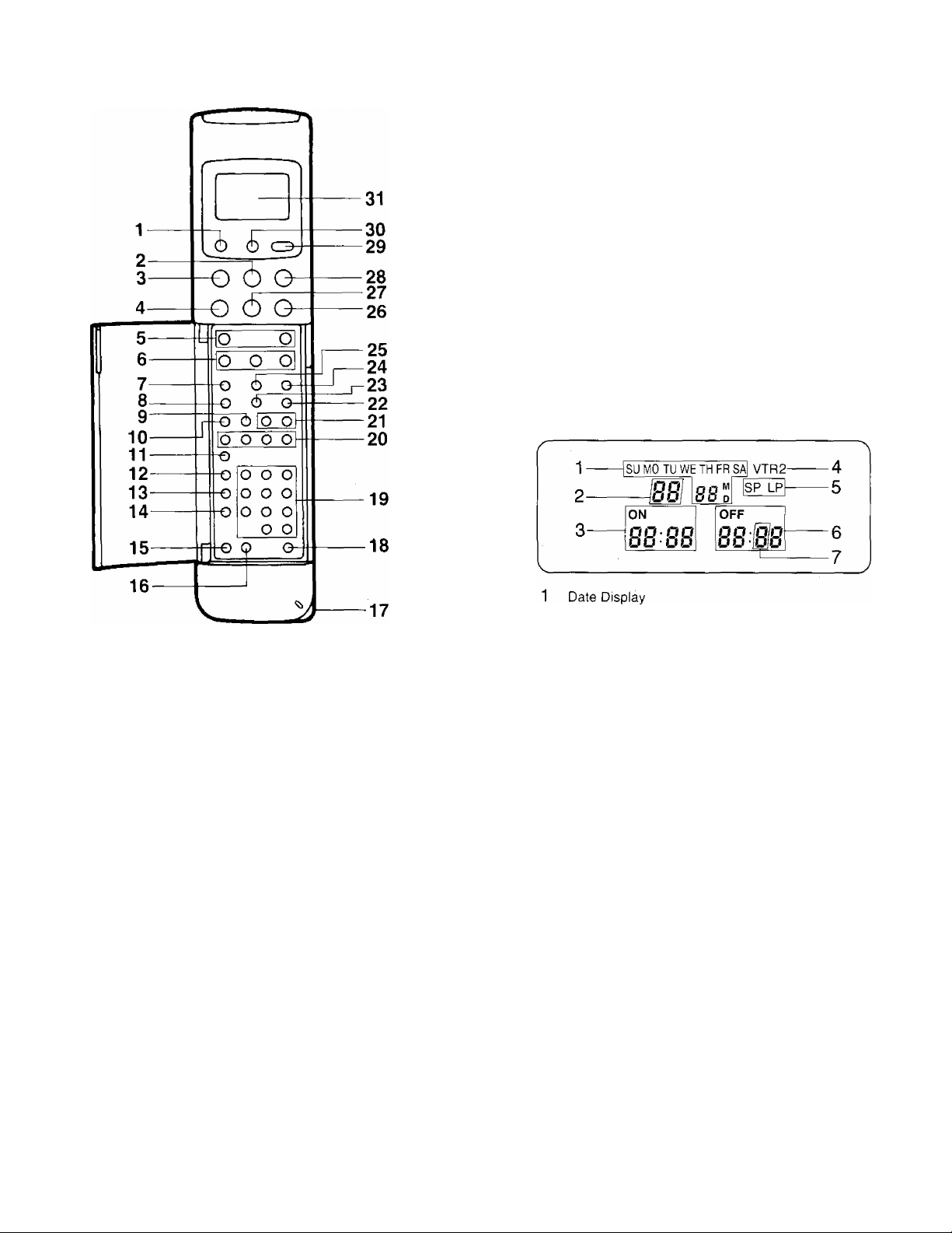
Infra-Red Remote Controller
19 Programme Position (Channel) Selector Buttons
20 Auto Play Buttons
21 Tracking/V-Lock “ + ” and Buttons
22 Input Signal Selector
23 VTR/TV Selector
24 Reset Button
25 Tape Remain Button
26 Fast Forward ►►/Cue @ Button
27 Play Button (►)
28 Still Advance Button (!!►)
29 Transmit Button
30 Digital Scanner On/Off Button
31 Display
1 VTR On/Off Button
2 Stop Button (■)
3 Pause/Still Button (II)
4 Rewind ◄◄/Review Q Button
5 Record Buttons
6 Slow Buttons
7 Clock/Counter Selector
8 Monitor Button
9 Time Search Button
10 Index Button
11 Audio Output Selector
12 Programme Button
13 Next Button
14 Tape Speed Selector
15 Timer Record Button
16 Cancel Button
17 Bar Code Reading Section
18 Remote Control Mode Select Button
2 Channel Display
3 Start Time Display
4 Remote Control Mode Indicator
5 Tape Speed Indicator
6 End Time Display
7 Check Indicator
Page 9
Infra-Red Remote Controller (Cont’d)
Power Source for the Remote Controller
■ The Remote Controller is powered by 2 lEC “R6” size
batteries. The life of the batteries is about one year,
however, it depends on the frequency of use. Inspect
and if necessary, replace the batteries once a year.
CAUTION FOR BATTERY REPLACEMENT
• Load the new batteries with their polarities (© and 0)
aligned correctly.
• Do not apply heat to batteries, or internal short-circuit
may occur.
• If you do not intend to use the Remote Controller for a
long period of time, remove the batteries and store them
in a cool and dry place.
• Remove spent batteries immediately and dispose of
them.
• Do not use an old and a new batteries together. (Also
never use an alkaline battery with a manganese battery.)
Load the batteries as follows:
1 Remove the battery compartment lid.
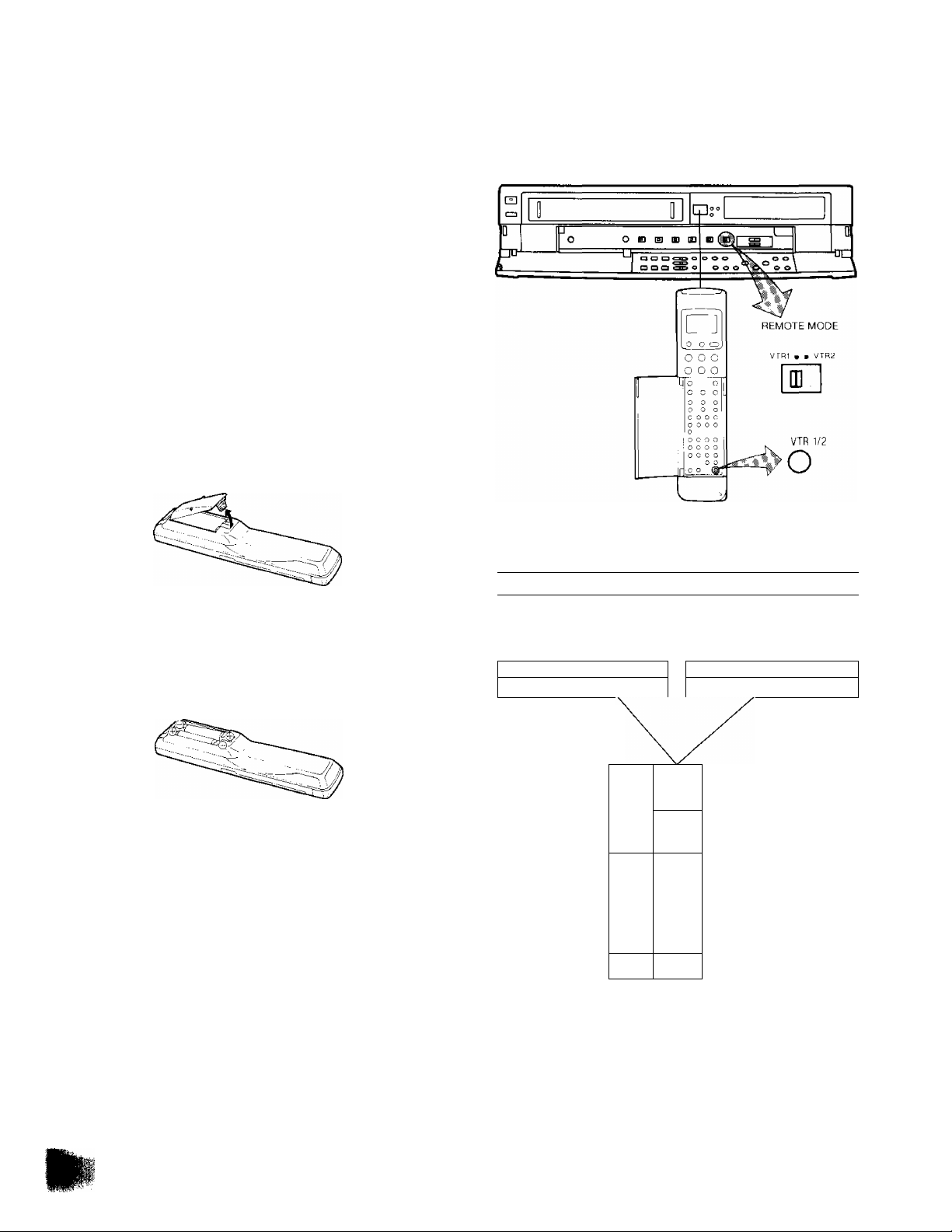
Remote Control Modes
This VTR can be remote controlled with two types of
signals. These signals are called Remote Control Mode
"VTR rand “VTR 2“.
When the Remote Control Mode Select Switch on the VTR
is set to “VTR 1 the Remote Control Mode Select Button
on the Remote Controller must also be set to “VTR 1
2 Place the batteries in the battery compartment as
indicated inside the battery compartment.
3 Replace the lid.
When using two Panasonic VTRs
Remote Control Mode
“VTR r
=|l! II ll«!-! 1,
----------- \------------------
1
When the Remote Control Mode Select Button on the
Remote Controller Is set “VTR 1 the VTR on the left can
be operated. When the Remote Control Mode Select Button
is set to “VTR 2", the VTR on the right can be operated.
• “VTR 2“ will appear in the Display.
In case of VTRs with switchable remote control modes, set
a different remote control mode for each of the VTRs so that
they can be operated individually with the same Remote
Controller.
Remote Control Mode
“VTR2 '
SITt' Ti|ori 1]
_
_
0 C О
ООО
-О о 1
0 о о !.
О G с
сое
О С С О
о О с с
1 О О О о
с О О с
1 G о О о !
с о 1
Г,0 о ,1
^
--
Page 10
Infra-Red Remote Controller (Cont’d)
How to Operate the Remote Controller
(Digital Scanner)
Press the Digital Scanner On/Off Button to “ON”,
• If no operation is performed for more than 25 seconds
(4 minutes during setting of the clock time), the scanner
will automatically switch over to the power-saving
standby condition and the lamp will go off. (In this case, if
bar codes have already been read but not yet
transmitted to the VTR, the data will be cancelled.)
•When the lamp is not lit, press the button to turn it “ON”
again.
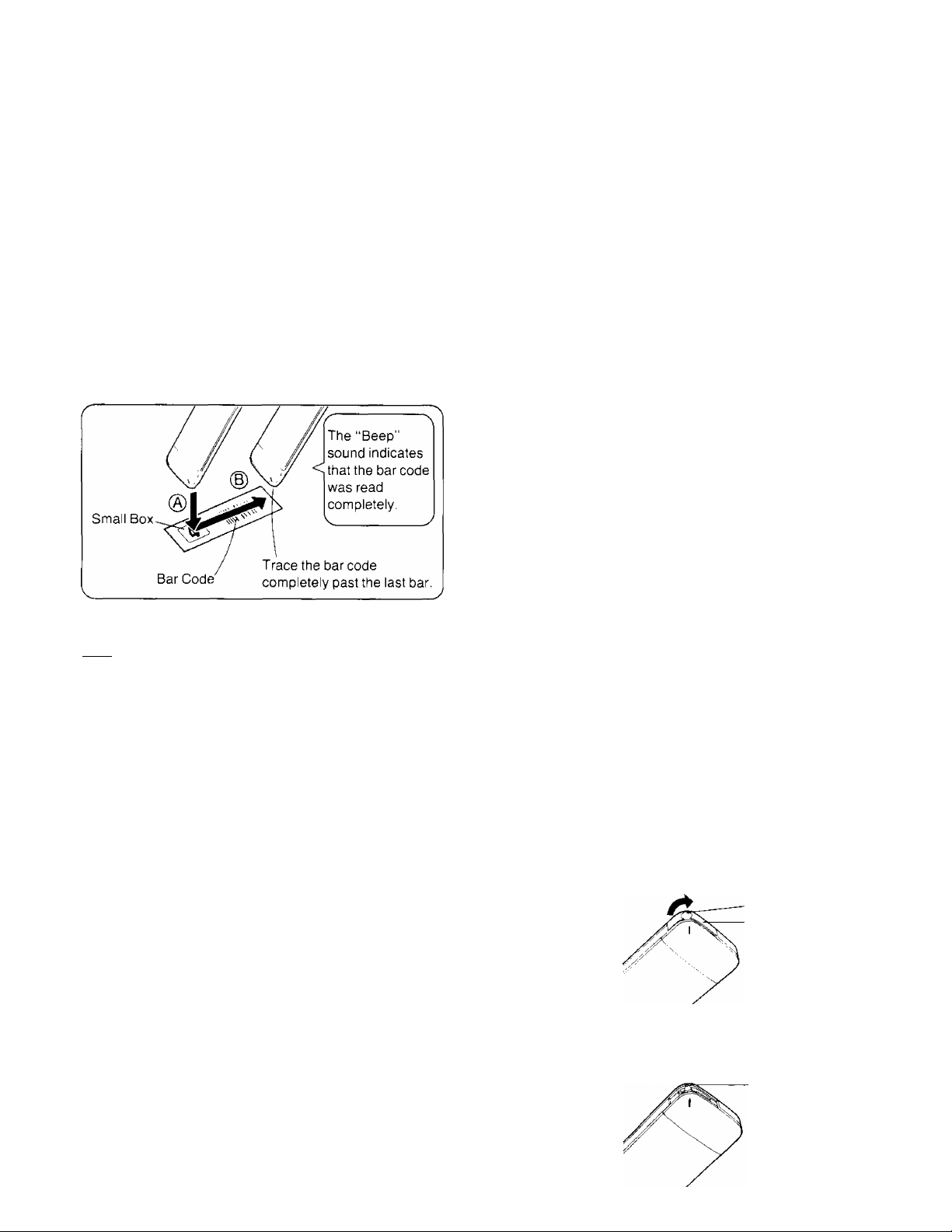
Tracing the Bar Codes
® Place the Remote Controller on the Small Box.
@ Trace the bar code quickly in the direction of the arrow.
When Remote Control Mode “VTR 2” is selected on the
VTR
________________________________________
Trace the “VTR 2” bar code on the Programming Sheet.
r-----------------------
ON
• “VTR 2” will appear in the Display.
When the “VTR 1 ” bar code is traced, the “VTR 2”
Indication will disappear and the remote control mode is
changed back to “VTR 1 ”.
D
OFF
VTR 2
•
•Treat the Programming Sheet with care. If the
sheet gets dirty or scratched, the bar code reading
may become impossible.
• Protect the Remote Controller from strong shocks
and vibration. Keep it away from water and places
with high temperature and humidity.
• If the bar code is traced slowly, it cannot be read
correctly,
•When there is no “Beep” sound, the reading of the
bar code is incomplete. Trace the bar code again.
•When using the Programming Sheet, put it on flat
surface: Reading the bar codes while holding it in
your hand or bending it, may result in incorrect op
eration.
• Do not deviate from the bar code, nor stop tracing
halfway.
V_________________________________________./
Note:
•The infra-red beam should be transmitted directly at the
Infra-red Remote Control Receiver on the front of the
VTR,
• Direct sunlight may interfere with the beam,
•The lightsensing angle of the Infra-red Remote Control
Receiver in the VTR is about 30^ for each side from the
centre.
•The unit should be used within a range of about 7 meters
from the front of the VTR.
Recommendation
After the programming of timer recording(s) is completed,
press the Digital Scanner On/Off Button so that the
indications in the Display disappear, in order to save
battery power.
When the Bar Codes Cannot be Read
Although the lamp in the tip of the Bar Code Reading
Section lights up:
• No figures appear in the Display
• No beep sounds is heard;
The tip of the Bar Code Reading Section is probably
clogged with dirt.
Cleaning
1 Remove the cap of the Bar Code Reading Section.
• Remove dirt and dust from the hole of the cap.
Hole
Cap
2 Gently wipe the tip of the lamp with a soft cloth.
• Reattach the cap by inserting it until it locks with a
click.
Lamp
10
Page 11
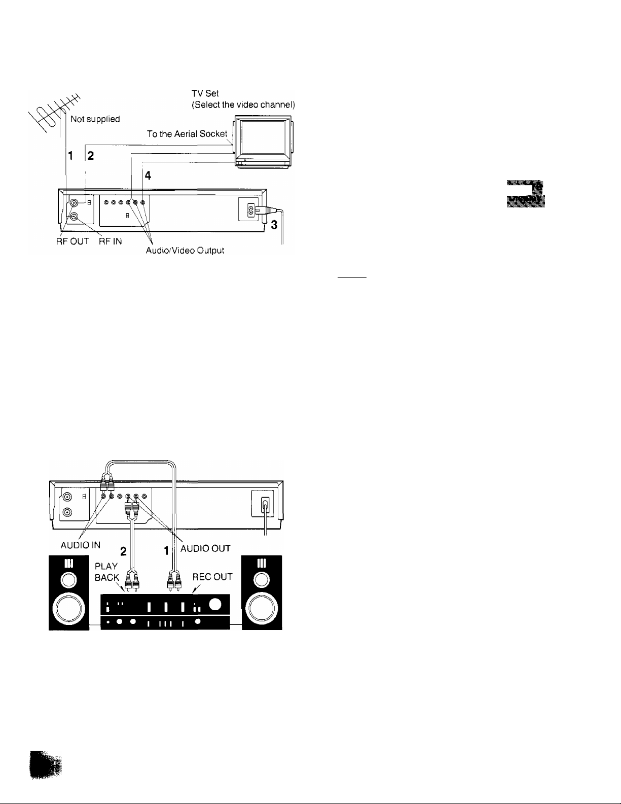
Installation
Connection to a TV Set VTR/TV Selector Button
With this button, distortion caused by interference between
TV broadcast signal and output signal from the VTR (VHF
channel 2 or 3) can be prevented. Use this button according
to the following table.
From the RF Output Socket of the VTR either signals of TV
broadcasts or from the VTR (RF convertor) are output.
■yFP''-*-
' ' ' ' ■ > H
k
iSi«
——
Connect the external aerial to the RF Input Socket on
the VTR.
Connect the aerial terminal on your TV set to the RF
Output Socket on the VTR with the supplied DIN-DIN
Coaxial Cable.
Connect the AC Mains Lead to the AC Mains Socket
of the VTR to the mains outlet.
If the TV set is equipped with separate video and audio
input sockets, it is recommended to connect the VTR to
the TV set with separate video and audio cables.
Connection to a Stereo Amplifier
TV ■■'eception is
possible.
TV reception is
■ ■ - ■
&rofr:':x;
TV reception can only be restored by pressing the VTR/TV
Selector Button. The “VTR” Indication in the Display will
disappear.
not possible.
TV reception is
not possible.
None
VTR
VTR
Stereo Amplifier
1 Connect the Audio Input Sockets on the VTR to the
REC OUT Sockets on the Stereo Amplifier.
2 Connect the Audio Output Sockets on the VTR to the
PLAYBACK Sockets on the Stereo Amplifier.
Not supplied
11
Page 12
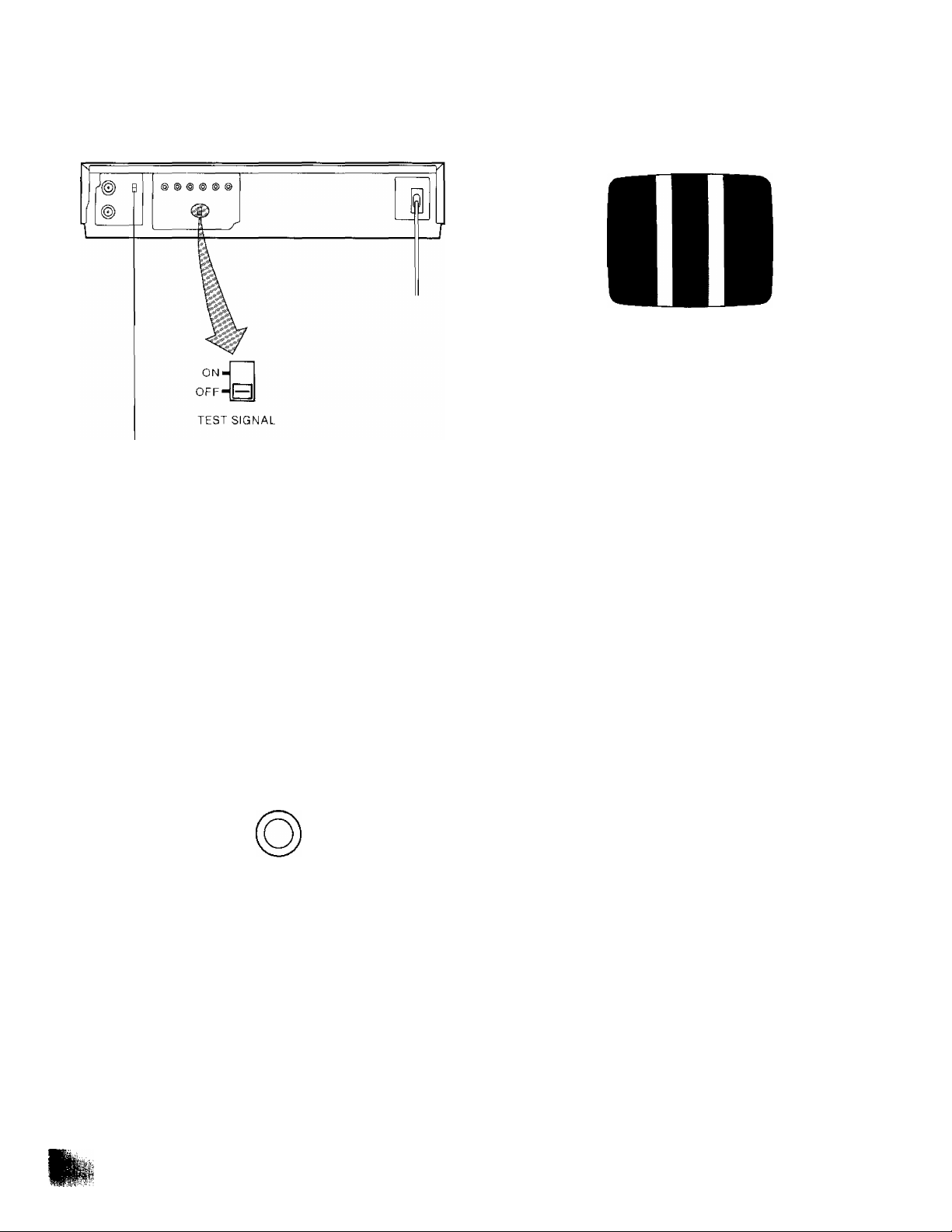
Tuning the TV Set to the Video Piayback Channel
The adjustments described on this page are not
necessary, if the VTR is connected to the TV set via the
Video/Audio output sockets.
Video Playback Channel Selector
This switch is used to select the video playback channel
which is not occupied with any TV station (2 or 3).
1
Turn the TV set on and select the AV programme
position or another programme position that is not
occupied by any TV station.
Press the VTR On/Off Switch to turn the VTR On,
{FRONT SIDE)
/ ^
5 Tune the selected programme position (Channel) of
the TV set to VHF channel 2 or 3,
Confirm on your TV set that the received test pattern
is as shown.
6 Set the Test Signal Switch to “Off", Your TV is now
ready to receive the RF output signal from the VTR.
ON
offHB
TEST SIGNAL
7 To check, play back a pre-recorded tape and confirm
picture quality.
VTR
•The corresponding indicator lights up.
Press the VTR/TV Selector so that the “VTR"
Indicator in the Multi-Function Display lights up,
VTR/TV
4 Set the Test Signal Switch to “On".
ON'
B
OFF'
TEST SIGNAL
—
12
Page 13
Setting the Tuner in the VTR
The tuner in the VTR makes it possible to receive TV
broadcasts and to record these programmes without having
to turn on the TV set.
TRACKING/
v-LocK—y:T::x
PROG'' RECORDING
BMiMil SP/LP _
NEXT
TIMER
RECE CANCEL
Preparation
•Turn the TV set on and select the programme position
(channel) which you have tuned to the video playback
channel.
• Press the VTR On/Off Switch to turn the VTR on.
• Press the VTR/TV Selector so that the “VTR” Indicator in
the Multi-Function Display lights up.
Press the “ + ” or Button until the picture of the
desired station on your TV is satisfactory.
•If the “ + ” or Button is pressed while pressing the
Next Button, the stations will change quickly.
i ^
j'FO i
T T T
During the station search
(The position indication
Tuned Condition
flashes on and off.)
•The tuned station is automatically memorized.
Repeat steps 2-4 for each channel you want to tune to a
station.
5 Press the Preset/Fine/Norm a I Button twice.
The indication on the Multi-Function Display changes
back to previous indication.
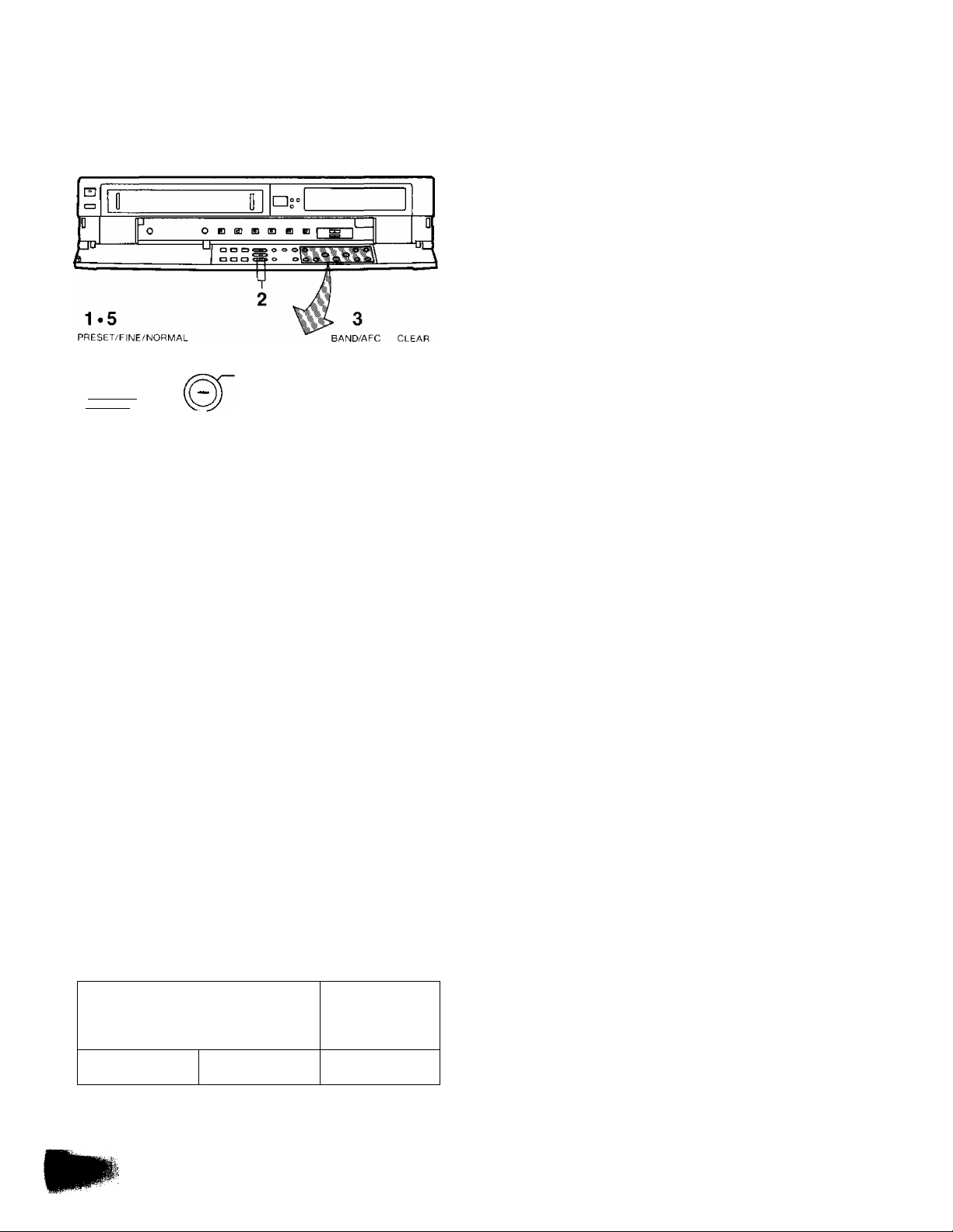
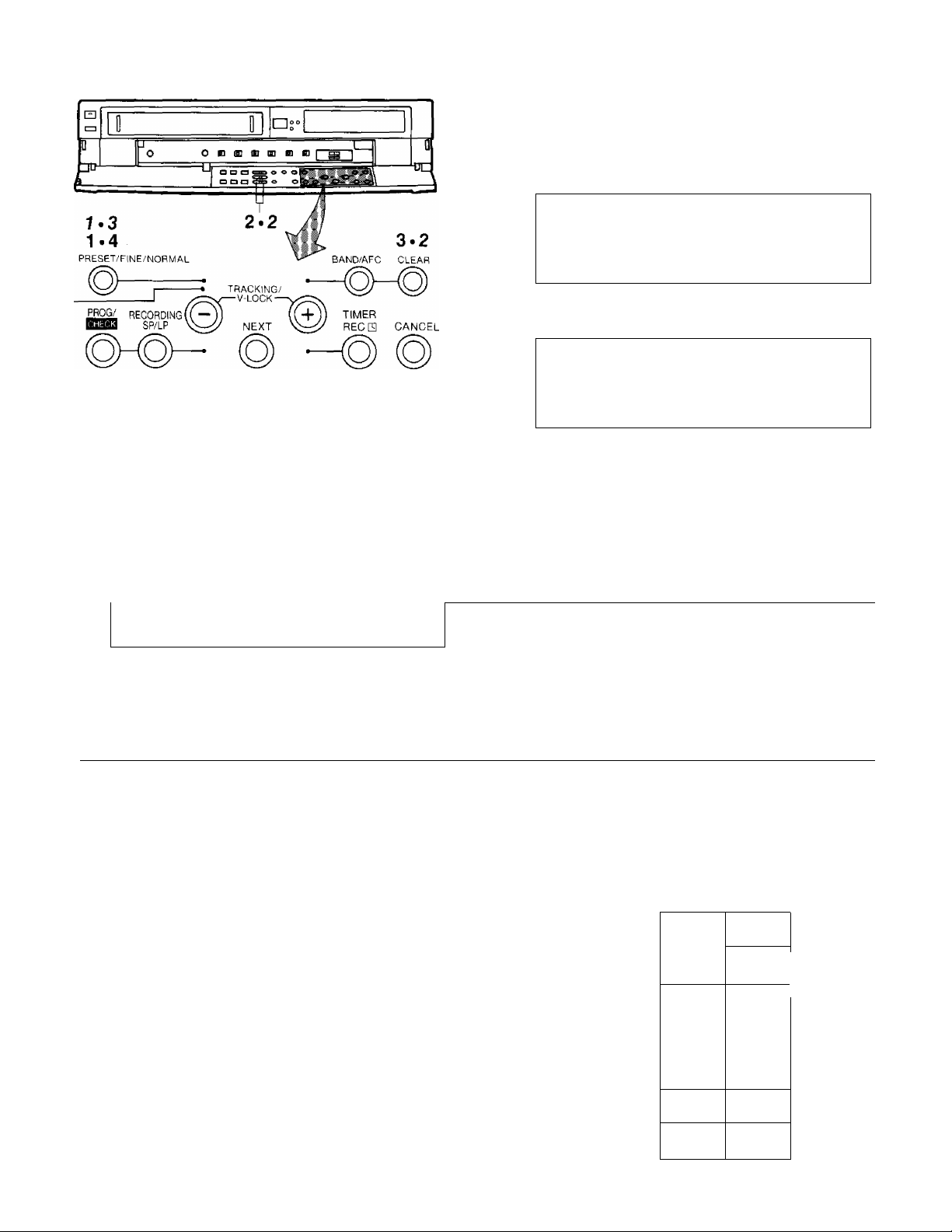
Tuning Procedure
1
Press the Preset/Fine/Normal Button on the VTR.
The indication on the Multi-Function Display changes
from the clock indication to the position indication.
Press the Channel Up or Down Button to select a
programme position (channel) which you want to tune
to a TV station.
Press the Band/AFC Button to select the “I”, “I
“U” position.
Display of the programme positions 1 -99
Indication of the
selected TV band
.... ^
i::::. j -jic;
or
1-3
4-11
21-69
The tuner in the VTR can be preset with up to 99 stations.
13
Page 14
Setting the Tuner in the VTR (Cont’d)
Fine Tuning Procedure
If fine tuning is necessary, for example for a weak station
which is close to a strong station;
1 Press the Preset/Fine/Normal Button twice.
r
i r;;; ^
Blanking of Unoccupied Programme Positions
Press the Preset/Fine/Normal Button.
Press the Channel Up or Down Button to select a
programme position (channel) which you do not want
to tune to a TV station.
Press the Clear Button (“- will be displayed in the
Programme Position Indication).
V ^ 5 =■■■■ O ■ y
• Repeat steps 2 and 3 for any programme positions
on which no stations are to be tuned. Afterwards,
these programme positions will be skipped during
Up/Down selection of the programme position.
4
^ress the Preset/Fine/Normal Button twice.
L PO i
2
^ress the “+” or
condition.
i
• “AFC” Indicator will not be displayed.
•To return the tuning to its former state, press the
Band/AFC Button.
Button to obtain the best tuning
i C
____
Ll:______________________^
‘ ■ = ■ = J
3 Press the Preset/Fine/Normal Button.
How to Select the Programme Position (Channel) on
the Remote Controller
select channel
1-9
10
20
11-99
for example 32
press button
-©
©
-> o
©
^©
©
-+ ©
©
respective channel
-©
-♦ ©
-»©
Cancelling the Clear Function (Blanking)
1 Press the Preset/Fine/Normal Button.
2 To cancel the blanking of a programme position,
select that programme position on the VTR and then
press the Clear Button.
3 Press the Preset/Fine/Normal Button twice.
If more than 5 seconds pass between the first, second and
third push, the channel will not be changed normally.
To Select an External AV Source:
Press the Input Signal Selector to select the “A1 '
programme position.
To select the signals which are input via Audio Input Socket
and Video Input Socket, select the “A1” programme
position.
1
_ __
1
0 CdJ
SU---------MO
-----
TU —
o © ©
WE
---------TH-----
FR —
o © ©
SA —SU'-SA-MO'-SA
O 0 o
o o o
o o
o o o .
O O O
O O
O O O 0
o o o o
o
o C'd'O
INPUT SELECT
o © ©►•
MO'FR
--------------
u *
- o o o
© ©
^
14
©
Page 15

Setting the Clock to the Present Time
The built-in digital clock employs the 24-hour system.
O D
a C3 o o o
2.12
CLOCK PRESET/FINE/NORMAL
3~11
TRACKING/
J"
VTR/TV ESS9 SR/LP
PROG'' RECORDING
v-LOCK—
NEXT
For Example: Set the clock for Sunday, October 10,
_________
• Connect the VTR to the mains outlet.
• Press the VTR On/Off Switch to turn the VTR On.
1999,9:10.
______________
1 When connecting this VTR to the mains or after a
long power failure, the indications flash.
7 Press the “-i-” or Button to set the date.
su
8 Press the Next Button.
9 Press the “-F” or Button to set the hour.
su
......
i i ^ ■ : i
D
......
10 Press the Next Button.
11 Press the “-f" or Button to set the minute.
su
: : .
D
12 Press the Clock Button when the present time
becomes exactly 9;10'00".
l"': . ^
> I I ' : : i i ^
T T T f T T f>^
__
2 Press the Clock Button to start the date and time
setting.
SA
^ : ; ; : r-
3 Press the “-R” or Button to set the year.
FR
^ : I ^
T
4 Press the Next Button.
5 Press the “-t-" or Button to set the month.
FR
i :i|
6 Press the Next Button.
su
J
At every push of the Next Button, the flashing indication
changes in the following order.
YEAR^MONTH^DATE^HOUR^MINUTE
• In case of a power failure, the timer back-up
system maintains the clock operation and timer
content for at least 60 minutes. However,
depending on the charging time and the memory
content, the back-up time may be considerably
longer. However, it takes more than 60 minutes for
the back-up circuit to become operational, after the
VTR is connected to the mains.
• The Timer Record Function should be set to “Off”,
otherwise the VTR cannot be operated normally. In
this case, the Timer Record Indicator “[3]’' will flash
to warn you.
• During date setting, the corresponding day is
simultaneously set.
•The clock/timer of the VTR is programmed with the
calendar up to the end of the year 2087.
The indications 88-99 are for the years 1988-1999.
The indications 00-87 are for the years 2000-2087.
15
Page 16

Setting the Clock to the Present Time (Cont’d)
Setting the Clock to the Present Time Using the Bar
Codes
■ iiii "
<1 1 1
H IMI “ Pill
■ 114 X mi
^ IH
1 IH < IIP
’ (iM - РРГ
□ Il il □ II í
^ Il 1
' и
* Il 1
» Il 1 X II1
*
11 1
X II 1
П « 1
1^ III 1
0 lin
N II 1
■ 1'
1
g 1Ш-
^ mi
" ftii
' II1
V 1 1 1
V III
»
11 1 1
.1 1 1
lili
un
11 1
'
нм
: III
■ =
: mi killl
' IH
i (III ь lili
.1. (Ilir
|:|
IIP
^ (III
D \.\A
■ III
' III
’
11 1
'■
m
•V 4 11
> H II .> Il 1
h IN
'' IMI
X mi
□ III
«HIM I
Preparation
• Press the Digital Scanner On/Off Button to turn it “ON”.
1 Trace the bar code “SETTING OF THE CLOCK”.
6 Trace the bar code for the minute (MIN).
I n
t и D
О (П
j- I и
7 Press the Transmit Button (Remote Controller) and
then confirm that the time is displayed in the
Multi-Function Display of the VTR.
2 Trace the bar code for the year (YEAR).
3 Trace the bar code for the month (MONTH).
t n
> и
4 Trace the bar code for the day of the month (DATE).
( П
< и □
5 Trace the bar code for the hour (START TIME).
8 Press the Digital Scanner On/Off Button to turn it
“OFF”.
• If the transmission was not received correctly, the
“Beep-Beep, Beep-Beep ’ sound from the VTR will warn
you. In this case, perform transmission again.
• If the Remote Controller is left with no operation
performed for more than 4 minutes, it will automatically
switch over to the power-saving standby condition and
the lamp in the reading tip goes out. In this case, bar
codes that have already been read (but not yet
transmitted to the VTR) will be cancelled.
•The bar codes “SETTING OF THE CLOCK”, “YEAR”
and “MONTH" are located on page 3 of the
Programming Sheet.
( Л
< и D
Cf • n n
J и и
16
Page 17

The Video Cassette
Inserting a Video Cassette (Auto Operation)
1 Insert the video cassette as shown. The VTR will be
turned on automatically and the cassette will be
automatically drawn into the VTR.
2 When a video cassette is inserted, the “ES” mark will
appear.
Notes;
•When a video cassette with broken out erasure
prevention tab (for example a pre-recorded tape) is
inserted, playback will start immediately.
• Use VMS video cassette tapes only.
•We recommend the “Panasonic Hi-Fi’’ high grade video
cassette tapes for improved picture and sound quality.
Removing a Video Cassette
Press the Eject Button (^).
¡EJECT
Simply press the Eject Button; the VTR turns itself on,
ejects the cassette and turns itself off again.
17
Page 18

Auto Operation
Convenient Automatic Playback Functions
The following convenient automatic playback operations
can be activated simply by pressing a single button on the
Remote Controller.
1 Repeat Playback
When the Repeat Button is pressed, the “R" Indication will
light up in the Multi-Function Display on the VTR and
playback will start. When the tape reaches the end of its
recorded portion, it will automatically be rewound to the
beginning and playback will then start again. This process
will be performed repeatedly.
coura
-Repeat Indicator
•The playback will continue until the VTR detects the
end of the video recording (no control signal for
more than 5 seconds). At this point, the tape will be
rewound to the beginning and the playback will be
repeated.
2 Memory Playback
When the Memory Button is pressed while the VTR is in
the Stop mode, the tape is then fast-forwarded or rewound
and it will be stopped at the tape counter position
“0:00.00”, and playback will then start from that position.
3 Sleep Playback
When the Sleep Button is pressed, playback will start. As
soon as the tape reaches the end of its recorded portion, it
will be automatically rewound to the beginning, and the
VTR will then turn itself off.
4 Rewind Playback
When the Rewind Button is pressed, the tape will be
rewound. As soon as the beginning of the tape is reached,
playback will start automatically.
Auto Operation
Auto VTR On
When a cassette is inserted, the VTR turns itself on
automatically.
Auto Play
When inserting a video cassette which has the erasure
prevention tab removed playback will start automatically.
Auto Rewind
When the tape reaches its end during recording (except
OTR and timer recording) or playback, it will automatically
be rewound to the beginning.
VTR-Off Eject
When the VTR is off, the inserted cassette can be ejected
simply by pressing the Eject Button, and VTR will
automatically turn itself off again.
Auto Head Cleaning Function
This VTR features a special function that automatically
removes tape particles and dust from the video heads to
ensure continuously superior picture quality. While the
Head Cleaning Function is working, some mechanical
noise may be heard from the VTR, However, this is not a
malfunction.
Beginning
of Tape
rum
Repeat Playback
PLAY
CZZ)
REW
To stop the Repeat Playback, press the Stop Button.
Note;
• If a short tape portion is played back many times, the
tape may become damaged at that part.
End of
Recorded Part
□z
------y------
Control signal Interruption
(at least 5 sec.)
•If the interruption of the control signal
is less than 5 seconds, the playback
will continue (no rewind from this point
and repeat).
n
18
Page 19

Playback
PAUSE/
STILL
II
Preparation
• Make sure that the Tinner Record Function is set to “Off”.
• Insert a recorded video cassette.
When a video cassette is already inside the VTR, press
the VTR On/Off Switch to turn it on.
•Turn the TV set on and select the video playback
channel.
•Set the Noise Filter/Edit Selector to “Off”.
STOP
4 Cue Playback
For short Cue playback (during normal playback), keep
the Fast Forward ►►/Cue Q Button pressed for as long
you want the tape to be played back at high speed in
forward direction.
For longer Cue playback (during normal playback), quickly
press the Fast Forward ►►/Cue Q Button to start the
Cue playback. To change back to normal playback, press
the Play Button (►).
r "
-O/FF
5 Review Playback
For short Review playback (during normal playback), keep
the Rewind ◄◄/Review Q Button pressed for as long
you want the tape to be played back at high speed in
reverse direction.
For longer Review playback (during normal playback),
quickly press the Rewind ◄◄/Review Q Button to start
the Review playback. To change back to normal playback,
press the Play Button {►).
REW/S3-
1 Normal Playback
Press the Play Button (►).
— PLAY —
•Control the picture as you like with the Picture
Sharpness Control (sharp or soft contours).
2 To Finish Playback
Press the Stop Button (■) to stop the playback.
•To be able to watch TV programmes, set the VTR/TV
Selector Switch to “TV”. The “VTR” Indicator will then go
out.
3 Super Still Playback
When the VTR is in the playback mode, press the
Pause/Still Button (I I) to view a still-picture. To continue
the normal playback, press the Play Button (►) or this
button again.
PAUSE/
STILL
.....................................
Note:
When Cue or Review playback continues for more than
10 minutes, the VTR will automatically switch back to the
normal playback mode.
II
► If you leave the VTR in the still playback mode for
more than 5 minutes, the VTR will automatically
switch over to the Stop mode to protect the tape and
the video heads.
19
Page 20

Playback (Cont’d)
Using the Remote Controller
6 Super Still Advance Playback
Press the Still Advance Button (ll^) while the VTR is in the
still playback mode. Each time you press this button, the
still-picture will advance one single field.
7 Super Fine Slow Playback
During normal playback, the Slow-motion playback can be
activated by pressing the Slow Button. The slow-motion
playback speed can then be varied by using the Slow
or Button,
Slow Tracking Control
•When noise bars appear during Super Still, Super Still
Advance or Super Fine Slow playback, switch over to
slow playback and adjust with the Tracking “-I-” or
Button to reduce the noise bars.
• It may not be possible to eliminate the noise bars
completely.
™ ^ ^ ---------------------------
•The sound will be played back only during normal
playback.
•When the picture rolls vertically in the Cue or
Review mode, adjust the vertical hold control on
the TV set.
• Immediately after starting Cue or Review playback,
the picture may be distorted. Also, when these
modes are cancelled, some momentary picture
distortion may occur. However, this is not due to
any malfunction.
• Noise which takes the form of horizontal bars
appears on the TV in the Cue and Review
playback modes. This is not an indication of a
malfunction.
•The top of the picture may become distorted in the
Cue, Review or Still mode. This is not an indication
of a malfunction.
• In “LP” mode only:
1. During any playback mode other than normal
playback, the picture may have some noise
bars, the colour may be unstable, or a black
and white picture may appear.
2. When playing back a tape which was recorded
on another VTR, it may be necessary to adjust
the Tracking Control. In some cases the picture
quality may still be inferior. This is due to
limitation of format.
---
"^When changing the slow-motion playback
speed, indicator flashes. ....
SLOW : li : ***..\
• Press the Play Button {►) to continue the normal
playback.
• If the Slow playback operation continues for more
than 5 minutes, the VTR automatically switches over
to the stop mode.
• While playing back a tape in the Super Still or Super
Fine Slow playback mode on a TV set equipped with
an automatic vertical hold control, the picture may
shake vertically. In this case, set the TV set’s
vertical hold (Auto/Manual) selector to the “Manual”
position, and adjust the vertical hold control.
20
Page 21

Playback (Cont’d)
►
Rewind and Fast Forward
Press the Rewind ◄◄/Review Q Button to rewind the
tape.
REW/®-
►►
NTSC Playback
When playing back tapes recorded in the NTSC system
with this VTR via an NTSC system TV set, set the VTR
System Selector to “4.43" or “3.58”.
When using an NTSC 4.43 system TV set:
Set the VTR System Selector to “4.43”.
When using an NTSC 3.58 system TV set:
Set the VTR System Selector to “3.58".
•When playing back tapes recorded in the PAL system with
this VTR via a PAL system TV set, set the VTR System
Selector to “PAL".
•Tapes recorded in the PAL system cannot be played back
with this VTR via an NTSC system TV set.
Press the Fast Forward ►►/Cue Q Button to wind the
tape forward rapidly.
-O/FF
Lap Time Counter
It shows the elapsed recording or playback time.
C0U^fT
1 Hours Minutes Seconds
The indication will appear when the tape is
rewound further than the tape counter position
“0:00.00".
• If the figures on the Tape Counter do not change during
Fast Forward, Rewind or any of the Playback functions,
this means that nothing is recorded on that tape section.
•The Tape Counter is automatically reset to “0:00.00”
when the video cassette is inserted.
•During playback of NTSC recordings, the Tape Counter
does not function correctly.
I
VTR SYSTEM
NTSC
-443
-3 58
[D
Playing back tapes recorded in the NTSC
system via a PAL system TV set
Tapes recorded in the NTSC system can be played back
with this VTR via a PAL system TV set.
Set the VTR System Selector to the “PAL" position.
•Depending on the TV set used, the picture may shrink
vertically and black bars may appear both at the top and
bottom of the screen.
This is not an indication of a malfunction.
•The playback picture may roll up or down. If the TV set is
equipped with a V-HOLD control, it may be possible to
stop the picture movement by adjusting this control.
However, if the TV set is not equipped with a V-HOLD
control, this condition cannot be corrected.
•When playing back a tape recorded in the NTSC system
SLP mode, the “LP” Indication in the Multi-Function
Display will light up.
•The special playback functions (except normal playback)
cannot be used for NTSC playback. This is not an
indication of a malfunction.
•Depending on the TV set used, the picture may be in black
and white. However, this is not an indication of a
malfunction.
21
Page 22

Playback (Cont’d)
V-LOCK
Digital Tracking
When playback is started after inserting a cassette, and
the VTR is turned on, the Digital Tracking function will be
activated automatically,
•When the tape speed (SP/LP) is changed, the Digital
Tracking function will be activated. However, when
operating any function other than playback, insert editing
and audio dubbing, this function will not work.
• During playback, the Digital Tracking function will be
activated whenever the playback changes over from an
unrecorded part to a recorded part, provided the
recorded part is longer than 4 seconds.
----------------—------------------------—
•When the picture is distorted by noise bars, press
the Tracking “ + ” or Button to select manual
tracking and adjust with these two buttons.
To change back to Digital Tracking, press the
Tracking and Buttons simultaneously.
Noise Filter/Edit Selector
EDIT ON: For editing operations such as dubbing.
OFF: For ordinary use of the VTR.
NOISE FILTER ON: For playback of tapes with inferior
picture quality caused, for example, by repeated dubbing.
^ ^ ^ —
•When the Noise Filter/Edit Selector is set to “EDIT
ON”, the picture sharpness cannot be adjusted
with the Picture Sharpness Control,
Tape Select Switch
To obtain a correct Remaining Tape Time indication when
using an E240 video cassette tape, this switch must be set
to the “E240” position.
When using E30, 60, 90, 120, 180 or 195 video cassette
tapes, set this switch to the “~E195” position.
When using an E260 video cassette tape, set this switch to
the “E260” position.
If cassettes with other tape lengths than the above are
used, the Remaining Tape Time indication will not be
precise.
Vertical Lock Adjustment
If vertical jitter occurs, adjust with the V-Lock or
Button during Still playback.
•When the AC Mains Lead is unplugged or a power failure
occurs, perform the vertical lock adjustment again.
22
Page 23

Playback (Coni’d)
CLOCK/
COUNTER-TAPE REMAIN
o o
MONITOR
O
Indication of the Remaining Tape Time
When the Tape Remain Button on the Remote Controller
is pressed during playback or recording mode, the
approximate remaining tape time will be displayed in hours
and minutes.
Clock/Counter Selector
By pressing this button when the VTR On/Off Switch is set
to “On”, it is possible to change over the display mode of
the Clock/Counter Display in the Multi-Function Display
from “Clock” to “Counter” Display and vice versa.
• Even if the selector button is set for “Counter” the
display will automatically changes over to XIock”
Display in all the following cases: When you set the VTR
On/Off Switch to “Off”, adjust the clock to present time,
programme a timer recording, check a timer recording
programme or programme and perform an OTR,
•When the Clock/Counter Display shows the time, the
counter cannot be reset.
Monitoring Function
When the Monitor Button is kept pressed during Playback
or Still playback, the broadcast picture of the selected
programme position (channel) or input signal through
Audio/Video input socket will be displayed. When this
button is released, the picture will change back to the
playback picture of the tape.
•The Remaining Tape Time Indication will remain
displayed even after the tape is ejected. However,
when next inserting a cassette, this indication will be
cancelled.
•When using a VHS-C videocassette in this VTR, the
remaining tape time indication may not be correct or
this indication may not appear at all.
•To return to the Tape Counter indication, press the
Tape Remain Button again.
23
Page 24

Recording from a TV Broadcast Signal
CD
II n b;"l
a
D
r
PAUSE/
STILL
II
4
0 ODiaoiinEiDi^l 1
L1 oodcd o <a o o o ol
STOP
■
3 2 1
J 1 1
O O o O \
RECORDING
SP/LP
kiL
-A
Preparation
• Make sure that the Timer Record Function is set to “Off".
• Insert a video cassette with the erasure prevention tab
intact.
When a video cassette is already inside the VTR, press
the VTR On/Off Switch to turn it on,
• Set the Tape Speed Selector to “SP” or “LP".
• Press the VTR/TV Selector so that the “VTR” Indicator
in the Multi-Function Display lights up.
•Adjust the audio recording level as described on page 27.
Tape Speed Selector {SP/LP)
For recording, either of two tape speeds can be selected.
During playback, the VTR will automatically select the
correct speed.
•SP Mode: For better picture quality.
• LP Mode; For longer recording time.
__________
_____
__
^ ^ ^ ^ ^ ^ ^ ^
It is not recommended to change from the SP to the
LP mode or vice versa in the middle of recording.
Even if the switching is done while the VTR is in the
pause mode, picture distortion will occur at the
switching point during playback.
•When a video cassette with broken out tab is inserted,
the “ESI’’ indication will flash, and an alarm sound will be
produced to indicate that recording is not possible.
• During recording, the programme position (channel) on
the VTR cannot be changed.
•To start a recording with the Remote Controller, press
the two Record Buttons on the Remote Controller
simultaneously,
•When a recording (including OTR and Timer Recording)
is started, the tape is played back for a short moment
before the actual recording starts, in order to achieve
smooth continuation from the previous to the new
recording. Therefore, the new recording starts about 1.5
seconds late.
To Finish the Recording
3 Press the Stop Button (■).
If You Wish to Avoid Recording Unwanted Material
4 Press the Pause/Still Button (I I
temporarily.
to stop the tape
PAUSE/
STILL
II
• Press the Pause/Still Button (II) again to continue
the recording.
• If you leave the VTR in the pause mode for more
than 5 minutes, the VTR will automatically switch
over to the stop mode to protect the tape and the
video heads.
VTR
[~RE^ SP
Recording One TV Programme While Watching
Another
1 Record (following steps 1 and 2).
2 Press the VTR/TV Selector so that the “VTR”
Indicator in the Multi-Function Display goes out.
3 Select the desired programme position (channel) on
your TV set.
Note:
The picture quality in the LP mode is not as good as that
in the SP mode.
1 Select on the VTR, the programme position (channel)
to be recorded. In order to confirm proper reception,
turn on the TV set and select the video playback
channel.
2 Press the Record Button.
laaa
VTR
FrecI SP
24
Page 25

Nicam System
The NICAM system is a ground-based TV service for digital
stereo sound. To receive NICAM broadcasts, the NV-F55
incorporates a NICAM decoder.
When a stereo, dual-soundtrack or monaural NICAM
programme is being received, the indicators light up to
inform you of the type of broadcasts. The NICAM
programmes are always accompanied by standard
broadcasts and you can select the desired soundtrack for
recording with a single switch. NICAM soundtracks can only
be recorded on the hi-fi audio track.
О
Recording of a NtCAM Stereo Programme
у— Ml STEREO
2CH О Ф
^—М2
О
The STEREO Indicator is lit while a NICAM stereo
programme is being received. To record such a
programme, set the Nicam/Mono Switch to “Nicam”.
NICAM stereo sound will be recorded on the hi-fi track and
the regular (standard) sound will be recorded on the normal
audio track.
Recording of a NICAM Dual-sound Track Programme
M1
■М2
STEREO
О
2CH
r~
Both the Ml and M2 Indicators are lit while a NICAM
dual-soundtrack programme is being received. To record
such a programme, set the Nicam/Mono Switch to “Nicam'
The Ml and M2 sounds will be recorded on the hi-fi track:
M1 on the left channel and M2 on the right channel.
Recording of a NICAM Monaural Programme
Ml STEREO
О О
М2
о
Only the M1 Indicator is lit while a NICAM monaural
programme is being received. To record such a
programme, set the Nicam/Mono Switch to “Nicam”
The same monaural sound will be recorded on both
channels of the hi-fi track.
Recording options according to the type of broadcasts and the setting of the Nicam/Mono Switch
^ ~ ----------------------------------------------------
,, , switch position
Type of broadcast
Regular broadcast (standard audio) Either position
Regular-i-NICAM stereo (L, R)
Regular-l-NICAM dual mono (M1, M2)
Regular-i-NICAM mono
Nicam/Mono
-----------
Audio track
NICAM
MONO
NICAM
MONO Standard audio Standard audio Standard audio
NICAM
MONO
Normal audio
track (mono)
Standard audio Standard audio
Standard audio Stereo L
Standard audio
Standard audio Ml
Standard audio Ml
Standard audio
Hi-Fi audio track
L
Standard audio
Standard audio Standard audio
R
Standard audio
Stereo R
Standard audio
M2
Ml
Note; NICAM audio programmes cannot be recorded on the normal audio track.
25
Page 26

Nicam System (cont’d)
Hi-Fi Audio System
OUT
o
Nicam/Mono Switch
•When a NICAM programme is being received, this switch
can be used to select the desired type of sound to be
recorded on the hi-fi audio track. To record a NICAM
programme, this switch must be set to “NICAM”.
Note:
If NICAM broadcast signals are weak, the sound quality
deteriorates remarkably. When the signals are extremely
weak, the Audio Recording Mode Indicator (M1, M2,
STEREO) goes off and the FM sound is recorded on the
hi-fi track irrespective of the setting of this switch.
•If the Nicam/Mono Switch is intentionally set to
“MONO” even through a NICAM programme is
being received, the indicator(s) remain lit.
•To record the regular sound (ordinary normal
sound) on the FM audio tracks when a NICAM
programme is received, set the Nicam/Mono Switch
to “MONO”.
•When a NICAM programme is received and the
sound is distorted due to inferior reception
conditions, set the Nicam/Mono Switch to “MONO”.
• Even if the “A1 ” programme position is selected,
the Audio Recording Mode Indicators may light up
according to the type of programme being
broadcast on the programme position selected on
the VTR.
However, this is not a malfunction.
o
Playback (or Monitoring during Recording)
Press the Audio Output Mode Selector to select the desired
sound mode.
At the every push of this button, the audio output mode
changes as follows.
E iiiiiiiiriiiiiii-iiiiiiiiiiiiiiiiiiii:
dB • 40 30 20 10 7 4 2 0 2 4 7 10 +
Stereo-^Left-^Right-^Normal audio track-
and the Left and Right Indicators show which sound mode
is selected in the following way.
Stereo: Both the Left and Right Indicators are lit.
Left: The Left Indicator is lit.
Right: The Right Indicator is lit.
Normal: Both the Left and Right Indicators are not lit.
•If a video cassette recorded on this VTR with stereo
or bilingual sound is played back on a conventional
VHS video recorder, the sound will be reproduced
from the normal audio track (in mono).
•Audio reproduction of linear (conventionally
recorded) stereo tapes will be monaural when
played back on the FM Hi-Fi video recorders.
____________
26
Page 27

Using the VTR as a Hi-Fi Audio Recorder
Preparation
•Connect the VTR to the Hi-Fi audio system. (Example of a
connection diagram is shown).
• Insert a video cassette with the erasure prevention tab
intact.
When a video cassette is already inside the VTR, press
the VTR On/Off Switch to turn it on.
•Switch on the Hi-Fi audio system and select an audio
source.
Hi-Fi Audio Recording
Note: Selection of an audio track is not necessary for
recording.
1 Press the Input Signal Selector on the Remote
Controller to select the “A1 ” programme position (or ■
select with the Channel Up or Down Button on the
VTR).
2 To start the recording, press the Record Buttons.
3 To achieve smooth transitions between adjoining
AUDIO IN AUDIO OUT
recordings, see notes on page 42.
Hi-Fi Audio Piayback
• Repeatedly press the Audio Output Mode Selector Button
so that the “Left” and “Right” Audio Output Mode
Indicators light up (for playback of both mono and stereo
recordings).
•To start the playback, press the Play Button (►).
FM Stereo Tuner
Adjustment of the Hi-Fi Audio Recording Level_________
Setting the Hi-Fi Rec Level Controls to the centre “5”
position (click stop) assures satisfactory audio recording
results in most cases. When using the VTR as a Hi-Fi audio
recorder or when producing your own video tapes, it may be
desirable to adjust the Hi-Fi Rec Level Controls to some
other position.
(It is recommended to adjust so that peaks in the audio level
reach about -i-4 dB.)
Hi-Fi REC LEVEL
0 I I I I I B I I I I
■mrm-
-Mi ni I 'm -
•The sound to be recorded on the “normal” audio
track will be adjusted automatically.
Record Player
27
Page 28

Super OTR Function (One-Touch Timer Recording)
This convenient function makes it possible to easily
programme the VTR for recording of TV programmes with
immediate start or with start within 24 hours by precisely
setting the starting time and ending time to the desired
minute, and the VTR will automatically turn itself off when
the recording ends.
1 ( ^ ml ^)
Preparation
• Insert a video cassette with the erasure prevention tab
intact.
When a video cassette is already inside the VTR, press
the VTR On/Off Switch to turn it on,
•Make sure that the dock shows the present time
correctly.
• Set the Tape Speed Selector to '“SP” or “LP”.
•Adjust the audio recording level as described on page 27.
It is possible to programme an OTR recording for a TV
programme which will start immediately or within the next
24 hours.
(For example, OTR recording of a TV programme
broadcast from 10:30 to 11 ;00.)
1 Select the programme position (channel) to be
recorded.
2 Press the OTR On ( + ) or (-} Button to set the OTR
starting time to 10:30.
3 Press the OTR Off {+) or (-) Button to set the OTR
ending time to 11:00
•When quickly and repeatedly pressing the OTR On { + ) or
(-) Button or the OTR Off (+) or (-) Button, the
corresponding time indication changes in 1 -minute steps.
When it is kept pressed, the indication changes in
10-minute steps.
•After setting the OTR starting time in step 2, the OTR Off
(+) or (-) Button must be pressed within 8 seconds to
select the OTR ending time, otherwise the selected
starting time will be cancelled.
After 4 seconds, the display will automatically change back
to the starting time indication.
To confirm the OTR ending time, press the Check/
Programme Button once. When this button is pressed
twice, the display will change to the clock indication mode.
•The VTR will automatically switch off, when the OTR is
completed. To turn the VTR on again, press the VTR On/
Off Switch,
•The “OTR” indicator will be displayed.
•When a video cassette with broken out tab is
inserted, the “Eig” indication will flash, and an alarm
sound will be produced to indicate that recording is
not possible.
28
Page 29

Super OTR Function (One-Touch Timer Recording) (Cont’d)
When the Programme/Check Button is pressed once, the
present time will be displayed.
When the Clock/Counter Selector Button (Remote
Controller) is pressed during OTR recording, the display
C - llll + )
1 ( ^ llll )
OTR Function with Immediate Start
For example; OTR recording of a TV programme
broadcast to 11:00.
1 Select the programme position (channel) to be
recorded.
2 Press the OTR Off “ + ’’or Button to set the OTR
ending time to 11:00.
•The “OTR" indicator will be displayed.
•When a video cassette with broken out tab is inserted,
the “E3" indication will flash, and an alarm sound will be
produced to indicate that recording is not possible.
• When quickly and repeatedly pressing the OTR Off “ + "
or Button, the corresponding time indication changes
in 1-minute steps. When it is kept pressed, the indication
changes in 10-minute steps.
•The VTR will automatically switch off, when the OTR is
completed. To turn the VTR on again, press the VTR
On/Off Switch.
will change over to the counter mode.
•When the tape reaches its end during an OTR the
VTR will turn itself off.
• Make sure that the OTR Function (One-Touch
Timer Recording) does not overlap a programmed
timer recording. An OTR always takes precedence
over a timer recording.
• It is possible to change the OTR starting time or the
ending time before the recording starts.
• It is possible to perform any VTR operation (except
timer recording) until the recording starts.
• It is possible to change the OTR ending time even
during the recording.
•To interrupt an OTR, press the VTR On/Off Switch
to turn the VTR off.
29
Page 30

Timer Recording
The programming of timer recordings is possible both on
the VTR itself and via the Remote Control Unit.
Programming of as many as 8 timer recording is possible
up to one month in advance.
CZD
1 1 1
Preparation
• Make sure that the clock shows the present time
correctly,
• Make sure that the Timer Record Function is set to “Ofr.
• Insert a video cassette with the erasure prevention tab
intact.
When a video cassette is already inside the VTR, press
the VTR On/Off Switch to turn it on.
•Adjust the audio recording level as described on page 27.
4 Press the or Button to set the date.
5 Press the Next Button.
6 Press the ‘‘-i-” or Button to select the hour of the
starting time of the TV programme.
7 Press the Next Button.
8 Press the “-i-" or Button to select the minute of
the starting time of the TV programme.
9 Press the Next Button.
10 Press the “+” or Button to select the hour of the
end time of the TV programme.
For Example:
Programming a timer recording for a TV programme that
will be broadcast on Wednesday, October 27, from 10:30
to 11:45, on programme position (channel) 12, on timer
programme number 2. (Present date=October 10, 1999)
1 Press the Programme/Check Button to select the next
unoccupied timer programme number.
• Press the Tape Speed Selector Button until the
Indicator of the desired tape speed (“SP” or “LP”) is
lit in the Multi-Function Display.
-----------------^------------------------
CO ■■■ ^ _
>TV
2 Press the “ + ” or Button to select the programme
position (channel) on which the TV programme will be
broadcast.
CD
MV
11 Press the Next Button.
12 Press the “-t-” or Button to select the minute of
the end time of the TV programme.
2
=.... 1 : gkf
V
_______________
Press the Timer Record Button.
r
•The tape speed (SP/LP) can be selected in any of
the steps 1 to 12.
2
{.Ml
J
3 Press the Next Button.
30
Page 31

Timer Recording (Cont’d)
For Everyweek Recording
For Example:
Programming a timer recording for a TV programme that
is broadcast every \week on Sunday, from 10:30 to 11:45.
Programming for everyweek recording can be made on
any of the timer programme numbers 1-8.
Perform the operation steps 1 to 3.
4 Press the Button repeatediy untii the “SU”
Indicator (^Sunday) is lit.
Perform the operation steps 5 to 13.
For Everyday Recording
For Everyday Recording, you have the choice between 3
different modes: Monday through Friday, Monday through
Saturday, and Sunday through Saturday.
MOTU WETHFR
--------
MOTUWETHFRSA -
SU MO TU WE THFR SA
For example:
Programme time for timer recording every day from 10:30
to 11:45 on timer programme number 8.
Programming for everyday recording can be made on any
of the timer programme numbers 1-8,
Perform the operation steps 1 to 3.
4 Press the Button until the desired type of
Everyday Recording {1, 2, 3} is displayed.
SP
V 11 É 11 1111 11
m: tl v'.'e t-f^
T T T1 M T Ï T T
Perform the operation steps 5 to 13.
To Confirm the Programme of a Timer Recording
Make sure that the VTR is turned on.
Make sure that the Timer Record Function is set to “On”.
Select the programme number to be checked, by
repeatedly pressing the Programme/Check Button.
The preset channel and start and ending times of the timer
recording will be indicated for about 12 seconds.
(start time}
(end time)
(4 seconds)
(next 8 seconds)
To Cancel a Timer Recording
Make sure that:
the VTR is turned on,
the Timer Record Function is set to “Off”.
1 Press the Programme/Check Button repeatedly, until
the number of the timer programme that you want to
cancel is displayed.
2 Press the Cancel Button.
• During recording, the programme position
(channel) on thé VTR cannot be changed.
•When you want to watch TV after setting a timer
recording, select the desired channel on the TV set.
• To cancel a timer recording during recording, set
the Timer Record Function to “Off”.
• It is impossible to confirm programmes of timer
recordings while an OTR is being performed.
•To turn the VTR on and use it for playback or
recording before the timer recording is performed,
set the Timer Record Function to “Off”.
•When the Timer Record Function is set to “On"
with no video cassette or a video cassette with
broken tab inserted, the “Ba” and “[3’’ indications
will flash. The indication will also flash, when
programming is not completely finished. While it is
flashing, an alarm sound will be produced to
indicate that recording is not possible,
• If a timer recording is not performed to the end (not
enough tape or cancelled by the user), the
programmed timer recording data will be cancelled
from the memory at 4 a.m. two days later.
However, if the Timer Record Function is activated
or an OTR recording is being performed at that
time, the programmed timer recording data will be
cancelled at 4 a.m, the next day.
31
Page 32

Timer Recording (Cont’d)
TIMER RECORDING BY USING THE
REMOTE CONTROLLER
How to select the programme position (channel)
To select a figure between 1 and 9, press the numeric
button corresponding to the number.
To select a 2-digit figure, first press the button and
then press the two corresponding numeric buttons one
after the other within 5 seconds.
How to set the Date and the Starting & Ending Times
for Timer Recording
To select a figure between 0 and 9, first press the numeric
button “0" and then press the numeric button
corresponding to the number.
To select a 2-digit figure, press the two corresponding
numeric buttons one after the other.
2
15
30
-► 0
O
o -► 0
-► 0
©
•When pressing the following buttons first, they will
immediately be input in the units digit.
For the date: "4”~“8” Buttons
For the hour; “3”-““9” Buttons
For the minute: “6”~'“9" Buttons
Example;
Programming a timer recording for a TV programme that
will be broadcast on the 3rd of the month, from 7:02 to
7:30, on programme position (channel) 4.
1 Press the Programme Button.
• Press the Tape Speed Selector Button until the
Indicator of the desired tape speed (“SP” or “LP”) is
lit in the Display.
2 Press the Number Buttons to select the programme
position (channel) on which the TV programme will be
broadcast.
3 Press the Next Button.
4 Press the Number Buttons to set the date.
5 Press the Next Button.
6 Press the Number Buttons to select the hour of the
starting time of the TV programme.
f
W 3o
•The second button must be pressed within 5 seconds
after the first button.
• Before pressing the Next Button, confirm that the figure
that you have input is indicated in the proper decimal
position in the Display.
•After inputting the minute, confirm that the minutes are
indicated as a 2-digit figure, before pressing the Next
Button.
• If the Next Button is pressed while a figure is only
indicated in the tens digit, it will be treated as a
programming error and will not be accepted.
• However, when no further figure is input within 5 seconds
after inputting a single digit, this figure will move to the
units digit.
32
7 Press the Next Button.
8 Press the Number Buttons to select the minute of the
starting time of the TV programme.
3o
SP
4
ON OFF
ill
T-nD:
"nn 3:
out
^ 1 H 1
Page 33

Timer Recording (Cont’d)
9 Press the Next Button.
10 Press the Number Buttons to select the hour of the
end time of the TV programme.
1 1 U L I ^ L J
V
- - - - - - - - - - - - - - - - - - - - - - - - -
11 Press the Next Button.
end time of the TV programme.
ON
~>nj
f-uc
:: 1-0 J
и - - - - - - - - - - - - - - - - - - - - - - - - - - - - - - - - - - - - - - - - - - ^
D SP
D D
OFF Vi
-------
13 Press the Transmit Button.
•The tape speed (SP/LP) can be selected in any of
the steps 1 to 12.
•When transmitting the programmed data to the VTR
without selecting the desired tape speed (SP or LP
is not lit in the Display), the tape speed indicated in
the Multi Function Display on the VTR will be
programmed for the timer recording.
•To immediately programme one more timer
recording, press the Programme Button two times
after transmitting the programming data of the first
timer recording to the VTR. Then programme the
second timer recording.
• If no operation is performed on the Remote
Controller for more than 25 seconds, it will
automatically switch over to the power-saving
standby condition and the indications on the Display
will disappear. In this case, the data which have not
yet been transmitted to the VTR will be cancelled.
Transmit the Programming Data
Keep pressing the Transmit Button and confirm that the
programmed data on the Multi-Function Display of the
VTR are as desired.
After releasing the button, the data will continue to be
displayed for about 12 seconds.
0 0
“Beep-beep-beep-beep-
beep...” sound indicates
programming is completed.
• If the transmission was not received correctly, the
“Beep-Beep, Beep-Beep’’ sound from the VTR will warn
you. In this case, perform transmission again.
• The transmission is possible when the VTR is turned on
but is not in any of the recording or playback operation
modes. It is also possible when the VTR is in the timer
recording standby mode (Ш indication is lit).
• If all programme numbers are occupied, the
“Beep-Beep, Beep-Beep” sound from the VTR will warn
you that the programming cannot be made.
•When the Transmit Button is pressed, the VTR will
automatically be put into the timer recording standby
condition and the VTR will be turned off.
•To operate the VTR before the timer recording will be
performed, press the Timer Record Button to suspend
the timer recording standby condition. After using the
VTR, be sure to press the Timer Record Button again,
otherwise the timer recording will not be made.
p r
q
Timer Recording from an Externai Source
For Example:
Programming a timer recording from some other AV
equipment connected to the Audio/Video Input Socket on
the 3rd of the month, from 7:02 to 7:30.
1 Press the Programme Button.
2 Press the Input Signal Selector so that the “A1 ”
Indication is lit.
Ч i i i i /
:o f:
I-
ON
Perform the operation steps 3 to 13 on pages 32 and 33.
33
D
OFF
SP
Page 34

Timer Recording (Cont’d)
For Everyweek Recording
For Example:
Programming a timer recording for a TV programme that
is broadcast every week on Sunday, from 7:02 to 7:30.
Perform the operation steps 1 to 3 on page 32.
4 Press the '‘9’’ Button and then the “1 ” Button within 5
seconds. The “SU” Indication (^Sunday) is lit.
Perform the operation steps 5 to 13.
For Everyday Recording
For Everyday Recording, you have the choice between 3
different modes: Sunday through Saturdayfij, Monday
through Saturday^, and Monday through Fridayf3j.
SU"-SA-MO'~SA-^
^ © ©► «2
MO-FR
3 0 G
For Example:
Programming a timer recording for a TV programme that
is broadcast everyday from 7:02 to 7:30.
Perform the operation steps 1 to 3 on page 32.
4 Press the “9” Button and then the “8”, “9” or “0”
Button within 5 seconds, according to the desired type
of Everyday Recording (1,2 ,3).
How to set Everyweek and Everyday Recording
First press the “9" Button and then press the desired
Number Button according to the desired type of
Everyweek or Everyday Recording.
Everyweek Recording
MO-SA
Sunday
Monday
Tuesday
Wednesday
Thursday
Friday
Saturday
Everyday Recording
Sunday through Saturday
Monday through Saturday
Monday through Friday
The second button must be pressed within 5 seconds after
the first button.
To Confirm the Programme of a Timer Recording
Make sure that the VTR is turned on.
Make sure that the Timer Record Function is set to “On".
Make sure that no figures are indicated in the Display of
the Remote Controller.
Select the programme number to be checked, by
repeatedly pressing the Transmit Button.
The preset channel and starting and ending times of the
timer recording will be indicated for about 12 seconds.
©►
MO'-SA
©►
MO-SA
©►
MO-~SA
©►
MO'-SA
©►
MO'-SA
©►
MO'-SA
©►
MO-SA
©►
MO-SA
©►
MO-SA
©►
SU
©
MO
©
TU
©
WE
©
TH
©
FR
©
SA
©
SU-SA
©
MO-SA
©
MO-FR
©
Perform the operation steps 5 to 13.
(start time)
(end time)
To Cancel a Timer Recording
Make sure that:
the VTR is turned on,
the Timer Record Function is set to “On”.
(4 seconds)
(next 8 seconds)
1 Press the Transmit Button repeatedly, until the
number of the timer programme that you want to
cancel is displayed.
2 Press the Cancel Button.
34
Page 35

Timer Recording (Cont’d)
(1^ CHANNEL Í2'DATE
a
lililí
m
llllllllilmillilll
1 [D-
-itttl-
B
lllllll
0
llllllllil
B
lllllilll
m
llllllllilalllllilll
ffi
lllllilll
B
lllllilll
M
lllillli
Jim
- M
a
m
la
a
m
a
m
IIIIIII!
IIIIIII
illilll
IIIIIII
lililí
illilll
illilll
IIIIIII
IIIIIII
TIMER RECORDING BY USING THE
DIGITAL SCANNER IN THE REMOTE
CONTROLLER
Tracing the Bar Codes
Example:
When programming a timer recording for a programme
that wiil be broadcast on channei position 4 on the 3rd of
the month, from 7:02 to 7:30, trace the bar codes in the
order of the numbered arrows shown.
• Press the Digital Scanner On/Off Button to turn it “ON".
1 Trace the bar code for “CHANNEL".
/
--------------
1_“
Trace the bar code for “DATE”.
I 1
H -
ON OFF
D
__
J
3 START TIME 0 '4 END TIME
] ¡lililí
] lililí
] illilll illlll
] llllllllil
] illlll Illlll
] llllllllil
] lililí
] lililí IIIIIII
n llllllllil
m»] illilll
RECORDING
RpI UmiHII
TIMER ON/OFF 1
5 Trace the bar code for “END TIME”.
@ IIIIIIIT iltlli
CANCEL 1
a
a
a
a
a
m
- 0
a
CHECK
3o
ON
*UC
6 Trace the bar code for “MIN”.
U
ON
1 nj
l-UL
7 Trace the bar code for “RECORDING” according to
the desired tape speed.
J
ON OFF
nz>
t'UL
OFF
n-nn
* uu
I
OFF
1 TH
i - DU
SP
3 D
n jn
I ■ Du
llllllllil
llllllllil
IIIIIII
llllllllil
¡IIIIIII
IIIIIII
lililí
lllllilll
3o
ON
OFF
1 - . - -
Trace the bar code for “START TiME”.
Í
ON
inn
1 t-uu
Trace the bar code for “MiN”.
Í ^
ON
3o
OFF
3o
OFF
_____
•The “Bee Bee Bee Bee Beeeeep" sound signals
that the scanner is now ready for data
)
J
)
35
transmission.
•When no sound is heard, read the bar codes once
again.
• If more than one bar code is read in the same
group, only the last code will be effective.
• If the “CANCEL” bar code is read, all bar codes
that have been read so far will be cancelled.
• If you do not trace the bar code for
“RECORDING”, the tape speed shown in the
Multi-Function Display will be programmed.
Page 36

Timer Recording (Cont’d)
Transmit the Programming Data
Keep pressing the Transmit Button and confirm that the
programmed data on the Multi-Function Display of the
VTR are as desired.
After releasing the button, the data will continue to be
displayed for about 12 seconds.
• If the transmission was not received correctly, the
“Beep-Beep, Beep-Beep" sound from the VTR will warn
you. In this case, perform transmission again.
•The transmission is possible when the VTR is turned on
but is not in any of the recording or playback operation
modes. It is also possible when the VTR is in the timer
recording standby mode (□ indication is lit).
• If all programme numbers are occupied, the
“Beep-Beep, Beep-Beep" sound from the VTR will warn
you that the programming cannot be made.
•When the Transmit Button is pressed, the VTR will
automatically be put into the timer recording standby
condition and the VTR will be turned off.
For Programming More Than One Timer Recording in
Succession
Repeat the following operation steps 1-3.
1
Trace the “CANCEL" bar code on the Programming
Sheet.
CANCEL
2 Trace the bar codes for “CHANNEL”, “DATE”,
“START TIME”, “END TIME” and “RECORDING”.
3 Confirm that the present time is displayed on the
Multi-Function Display of the VTR, and transmit the
data.
• If the next timer programming data are transmitted
while the previous timer programming data are still
being displayed, the displayed timer recording data
will be cancelled.
Timer Recording from an External Source
For timer recording of signals input from some other AV
equipment via the Audio/Video Input Socket on this VTR,
trace the “ AV ” or “ AV 1 ” bar code in the “CHANNEL”
column.
Note:
The “AV 2” bar code cannot be used with this VTR,
TIMER ON/OFF
After programming a timer recording, the VTR is in the
timer recording standby mode and cannot be used for any
other operation, such as playback. If some other operation
is desired, first trace the “TIMER ON/OFF” bar code and
transmit it to the VTR with the Transmit Button,
To later reset the VTR to the timer recording standby
mode, trace the “TIMER ON/OFF” bar code again and
transmit it with the Transmit Button.
TIMER ON/OFF
B-
r
L
.J
36
Page 37

Timer Recording (Cont’d)
For Everyday Recording
When programming an everyday recording using the bar
codes, you have the choice between 3 different modes:
Sunday through Saturday {1), Monday through Firday (2),
and Monday through Saturday (3).
(SU-SA)
□
(MO-FR)
□
(MO~SA)
□
1
1 Turn on the Digital Scanner and trace the
“CHANNEL" bar code.
2 Trace the desired “EVERYDAY" bar code {1, 2, 3).
(SU-SA)
Q-
SUMOTU WE TH FR SA
1
I
ON OFF
3 Trace the bar codes for “START TIME", “END TIME"
and “RECORDING", and transmit the data to the VTR.
SU MO TU WETH FRSA
SP
ON
nn
8
•uu
• Everyday recording will be performed from that day on.
• If a “DATE" bar code is traced after tracing the
“EVERYDAY" bar code, everyday recording will not be
performed.
For Everyweek Recording
OFF
innn
>u uu
1 Turn on the Digital Scanner and trace the
“CHANNEL" bar code,
2 Trace the bar code for the desired day of the week
among the “EVERYWEEK” bar codes.
EVERYWEEK
Sunday
Monday
T uesday
Wednesday
-------------
------------
-----------
------
-H
-u
-H
Trace the bar codes for “START TIME”, “END TIME”
and “RECORDING”, and transmit the data to the VTR.
• Everyweek recording will be performed from that week
on.
• If a “DATE" bar code is traced after tracing the
“EVERYWEEK” bar code, everyweek recording will not
be performed.
To Confirm the Programme of a Timer Recording
To perform this operation, the VTR must be turned on or it
must be in the timer recording standby mode (H indication
is lit).
1
Trace the “CHECK” bar code.
CHECK
r
L
Perform transmission.
•After releasing the Transmit Button, the
programmed data will be displayed for about
12 seconds on the Multi-Function Display,
•At every push of the Transmit Button, the timer
programme number advances to the next higher
number.
To Cancel a Programmed Timer Recording
To perform this operation, the VTR must be turned on but
not be in any of the recording or playback operation
modes, or it must be in the timer recording standby mode
{H] indication is lit). To cancel a programmed timer
recording, its data must be displayed on the Multi-Function
Display. If they are no longer displayed, first, trace the
“CHECK" bar code and perform transmission (several
times, if necessary, until the programme you want to
cancel is displayed). Then, within 12 seconds:
1 Trace the “CANCEL" bar code.
2 Perform transmission,
•To programme a new timer recording, perform the
programming from the beginning.
Thursday
Friday
--------------
Saturday
----
-
-m
37
Page 38

VHS Index Search System
With the VHS Index Search function, up to 99 addresses
(places where index signals are recorded) can be skipped
to directly locate the beginning of the desired programme
in both forward and reverse direction in the Fast Forward
or Rewind mode.
1 Press the Play Button (►) or Stop Button (■).
2 Press the Index Button.
Input the number of programmes that you want to
skip by pressing the number buttons.
4 Press the Rewind ◄◄/Review @ or Fast Forward
►►/Cue (3 Button to start the VHS Index Search
function (the VTR will switch to the rewind or
fast-forward mode).
• Every time an index signal (address) is skipped the
number in the Address Indication decreases by one.
•When the preset address is reached, the Tape Counter
Indication will appear in place of the Address Indication,
and the normal playback will start.
•To abort the Index Search function midway, press the
Play or the Stop Button.
Recording of Index Signals
While recording an index signal, the indication “WRITE"
on the Multi-Function Display lights up for a few seconds.
Index signals will be recorded automatically in the
following cases;
•At the tape position at which the Record Button is
pressed to start recording.
•At the tape position at which a Timer Recording is
started.
•At the tape position at which an OTR recording is started.
•When pressing the Record Button during recording.
•When activating the VHS Index Search function
from the Still playback mode, the Playback will
start when the selected programme is reached.
• If the VHS Index Search function is started
extremely close to the beginning of the next
programme (place where an address signal is
recorded) or from the beginning of the tape, the
first address may not be counted.
• If there are unrecorded parts on the tape, or if
recordings have repeatedly been made on the
same tape portion, the VHS Index Search function
may not work correctly.
•The VHS Index Search function can only count the
addresses correctly, if the index signals are
spaced at least 3 minutes in the SP mode and
5 minutes in the LP mode.
• If you made a mistake, press the Index Button twice
and input the correct number.
38
Page 39

Intro Scan Function
How the Intro Scan Function Works...
Tape is
fast-forwarded
Playback for about
10 seconds
tf'ir
1_K
Programme Programme
Index Signal
The Intro Scan function plays back the first 10 seconds of
each programme (recorded with index signal) on a tape
one after another. This is convenient for quick checking
what programmes are on a tape, or to find the desired
instalment of a TV series you have recorded on a tape.
Insert a video cassette.
(Put the VTR in the stop mode.)
Press the Index Button.
Press the Fast Forward ►►/Cue Q Button.
(The Intro Scan starts.)
When the desired scene is reached, press the Play
Button (►).
Programme
•Operation is repeated until tape reaches its end.
Performing Index Repeat Playback
^ Index Signal
n
-------------------
Repeat Playback
PLAY
REW
1 Press the Index Button,
2 Press the Repeat Button. The “RS" Indicator lights up
and playback starts.
•When the next index signal is found, the tape will be
rewound. When the index signal, where the
playback is to start, is found, the playback will
restart. In this way, automatically repeated playback
can be performed for a tape portion as defined by
the number of index signals that are skipped.
3 To stop the Index Repeat playback, press the Stop
Button,
If Index Repeat playback is performed on a tape for
long periods of time, the picture quality may become
inferior.
Programme
•The Intro Scan function may not be activated for
the first programme recorded close to the
beginning of the tape.
•The Intro Scan function may not be activated, if the
interval between programme starts is less than
5 minutes in the LP mode, or less than 3 minutes
in the SP mode.
39
Page 40

Time Search
The Time Search function makes it possible to quickly
advance the tape from any position by inputting the exact
desired amount of playback time of the part that you want
to skip.
'Present position
10.00
10 minutes from
beginning of tape
15.43
15 minutes
43 seconds from
beginning of
4 Press the Fast Forward ►►/Cue @ Button or the
Rewind ◄◄/Review @ Button.
The playback starts after rewinding or fast forwarding
to the tape position of the designated time.
Time Search from the Play Mode
The operation is the same as that for the stop mode but in
operation step 4, the Cue or Review playback is performed
to the tape position of the designated time and the
playback will then start.
If the time search function is activated during playback, a
time of up to 59 minutes 59 seconds can be input.
•The numbers in the Tape Counter do not change
during parts of the tape on which there is no
recording.
•When the tape is inserted, the Tape Counter will
automatically be reset to “0:00.00".
1 Put the VTR in the stop mode.
2 Press the Time Search Button.
The indication in the Multi-Function Display changes
as shown below.
/
Input the time of the desired scene.
• The time is input by pressing the number buttons in
the order: hour, minute, second.
•The indication will be counted as “0".
COUrJT
COUNT
40
Page 41

Camera Recording
• For playback of a tape that was recorded via a
camera, select the audio track on which the sound
from the camera microphone was recorded by
pressing the corresponding Audio Output Selector,
• If you leave the VTR in the pause mode for more
than 5 minutes, the VTR will stop automatically to
protect the tape and the video heads.
• Even if the video camera is equipped with video
recorder remote control functions, this VTR can
not be remote-controlled from the camera.
Preparation
•Connect the Video Camera via the Camera AC Adaptor
to the VTR as shown in the illustration above,
• Insert a video cassette with the erasure prevention tab
intact.
When a video cassette is already inside the VTR, press
the VTR On/Off Switch to turn it on.
• Press the Input Signal Selector on the Remote Controller
to select the “A1 ” programme position (or select with the
Channel Up or Down Button on the VTR).
• Set the Tape Speed Selector to “SP" or “LP”.
•Adjust the audio recording level as described on page 27.
1 Turn Ihe Camera AC Adaptor on and make the
necessary adjustments on the camera.
Refer to the operating instructions of the camera you
are using.
2 Press the Record Button on the VTR to start recording.
Avoid recording unwanted material:
Press the Pause/Still Button (II) of the VTR, and the
recording will stop temporarily. To restart recording, press
the Pause/Still Button (II), again.
3 Press the Stop Button (■) on the VTR to stop the
recording.
41
Page 42

Dubbing (Copying)
Dubbing (copying) from one video cassette to another.
AUDIO OUT VIDEO OUT
(Supplied)
Preparation
• Make the necessary connections as shown in the
connection diagram.
• Press the VTR On/Off Switches to turn both VTRs on,
• Press the Input Signal Selector on the Remote Controller
to select the “A1” programme position (or select with the
Channel Up or Down Button on the VTR).
• Make sure that the Noise Filter/Edit Selector of both the
recording and playback VTRs (if equipped) are in the
“EDIT ON” position. Set these switches to “OFF" for
ordinary use of the VTRs.
(The Noise Filter/Edit Selector is on the front panel.)
•Adjust the audio recording level as described on page 27.
(Recording VTR)
1 Place the recorded cassette in the playback VTR and
a blank video cassette with the erasure prevention tab
intact in the recording VTR.
2 Press the Record Button on the recording VTR.
3 Press the Play Button (►) on the playback VTR.
4 Press the Stop Button (■) on both VTRs to stop the
dubbing.
•To assure smooth, noiseless cuts when
interrupting the recording, always use the
Pause/Still Button (II).
•To obtain smooth cuts when starting the recording
from the stop mode;
Play back the last part of the previously
recorded material to confirm its ending point,
and then press the Pause/Still Button (II).
2,
Press the Record Button.
(The VTR is still in the pause mode.)
3. To start recording, press the Pause/Still Button
(II) again.
The picture quality of a re-recorded tape is not as
good as that of the original.
VTR System Selector
______________________________
When dubbing an NTSC system tape, set the VTR System
Selectors on both the recording and playback VTRs to
“4.43” or “3.58”.
When dubbing NTSC 4.43 system:
Set the VTR System Selector to “4.43”.
When dubbing NTSC 3.58 system:
Set the VTR System Selector to “3.58”.
•When the VTR System Selector is set to “4.43” or “3.58”,
PAL signals cannot be recorded correctly.
•When dubbing a PAL system tape, set the VTR System
Selectors on both the recording and playback VTRs to
“PAL”.
E
c:=3
I II
r
A o o o o o o o o
H A I__________________________________
I 0 ODO D D B
VTR SYSTEM
NTSC
-4.43
-3 58
nr
-------
-0
A
m
42
Page 43

Insert Editing
When this type of editing is done, the picture and the sound
are recorded on the tape as shown below. However, if no
new sound is input, the original sound remains only on the
“normal" audio track of the tape because the original Hi-Fi
sound will always be erased during insert editing.
By performing insert editing together with audio dubbing,
the sound on the “normal" audio track can also be replaced
at the same time.
Video and Audio Track Recording Pattern
Preparation
• Insert a video cassette with the erasure prevention tab
intact.
•When performing insert editing from another VTR, set
the Noise Filter/Edit Selector to “EDIT ON”.
• Press the Input Signal Selector on the Remote Controller
to select the programme position according to the type of
insert editing to be performed.(Or select with the
Channel Up or Down Button on the VTR.}
1 ~99: When inserting picture and sound from a TV
programme.
A1
When inserting picture and sound from
equipment connected to the Video Input Socket
and the Audio Input Socket.
1 Press the Play Button (►).
2 Locate the tape position where you want the insert
editing to end, and press the Pause/Still Button to put
the VTR into the still playback mode.
3 Press the Reset Button (Remote Controller) to reset
the Tape Counter to “0:00.00".
4 Perform review playback to locate the tape position
where you want the insert editing to start and put the
VTR into the still playback mode.
5 Press the Insert Editing Button.
(The Insert Editing Indicator lights up.)
If you want to replace the sound on the “normal” audio
track, too, press the Audio Dubbing Button.
(The Audio Dubbing Indicator lights up.)
6 After the picture to be inserted is prepared, press the
Pause/Still Button (II).
(The insert editing will start.)
•The insert editing will end at the point where the
Tape Counter indicates “0:00.00", and the editing
VTR will stop in the still playback mode.
Playback of a Tape on Which Insert Editing Was
Performed
The sound inserted during insert editing is recorded on the
Hi-Fi sound tracks (STEREO, LEFT, RIGHT), if the normal
sound track is selected, the original sound before the insert
editing will be heard. Select the desired sound with the
Audio Output Mode Selector.
Hi-Fi/Normal Mix Switch
Set this switch to “On", if you want both the “Hi-Fi” sound
and the “normal” sound to be played back mixed together.
• The mixed sound may not be very clear.
Always set this switch to “Off", except when playing back
a tape on which the insert editing or audio dubbing was
performed.
~ .
• It is not necessary to operate the Tape Speed '
Selector.
•The picture quality of an inserted part is always
somewhat inferior to that of the original.
•Avoid performing insert editing repeatedly on the
same part of the tape because the picture quality
of that part becomes inferior.
•The inserted picture may contain slight colour
noise or the colours may be unstable.
• If insert editing is performed on a tape recorded in
the NTSC system, the insert editing function will
not work correctly.
43
Page 44

Audio Dubbing
Note that the original sound on the “normal" (mono) sound
track will be completely erased during audio dubbing.
PAUSE/
STILL STOP laaa
____
II
2-4
Preparation
• Insert a video cassette with the erasure prevention tab
intact.
When a video cassette is already inside the VTR, press
the VTR On/Off Switch to turn it on.
• Press the Input Signal Selector on the Remote Controller
to select the “At ” programme position (or select with the
Channel Up or Down Button on the VTR).
•Turn the TV set on and select the video playback
channel.
• Select the “normal" (mono) sound track by repeatedly
pressing the Audio Output Mode Selector until the Audio
Output Mode Indicators “Left” and “Right” are no longer
lit.
1 Press the Play Button (►) to look for the point where
you want to start the audio dubbing.
2 Press the Pause/Still Button (I I) at the exact point
where you want to start the audio dubbing.
3 Press the Audio Dubbing Button (the indicator will
light up).
4 Press the Pause/Still Button (II) once again to
release the tape from pause, and at the same time
start the operation of the audio source. The audio
dubbing will start.
5 Press the Stop Button (■) to stop the audio dubbing.
Playback of a Tape on Which Audio Dubbing Was
Performed
The sound inserted during audio dubbing is recorded on the
normal sound track. If the Hi-Fi sound tracks (STEREO,
LEFT, RIGHT) are selected, the original sound (before the
audio dubbing) will be heard.
Hi-Fi/Normal Mix Switch
Set this switch to “On”, if you want both the “Hi-Fi" sound
and the “normal" sound to be played back mixed together.
•The mixed sound may not be very clear.
Always set this switch to “Off", except when playing back
a tape on which the insert editing or audio dubbing was
performed.
/■ ^
•Sound recorded by using the audio dubbing
function is recorded on the “normal” audio track
(always in mono).
• When a microphone is used for dubbing, do not
place it near the speaker of your TV to prevent
howling noise (acoustic feedback).
• If the erasure prevention tab of the cassette is
missing, no audio dubbing can be made.
• If audio dubbing is performed on a tape recorded
in the NTSC system, the audio dubbing function
will not work correctly.
44
Page 45

Before Requesting Service
Before requesting service, check the following points once
again.
SYMPTOM
Power doesn’t turn on.
Power is on but unit doesn’t
operate.
VTR has turned itself off.
TV programmes cannot be
recorded.
OTR Function (One-Touch
Timer Recording) cannot be
performed.
Unattended timer recording
cannot be performed.
CAUSE REMEDY
Mains lead is not connected. Connect mains lead to mains outlet.
The Timer Record Function is set to “On”. Set the Timer Record Function to “Off".
Safety devices are operating.
Dew condensation inside the VTR.
Safety devices are operating.
Connection of aerial lead is not correct.
Reception channel is not properly tuned.
Clock is flashing “0:00”.
Recording start or recording stop time
setting is incorrect.
Turn off the VTR On/Off Switch, disconnect
mains cord from outlet, then reconnect mains
cord to mains outlet and turn on the VTR
On/Off Switch again.
Wait until the Dew Indicator “ H ” goes off.
Turn the VTR on again by pressing the VTR
On/Off Switch.
Connect aerial lead correctly.
Tune reception channel.
Set clock to present time.
Set recording start and recording stop time
correctly.
Recording via external input
terminals cannot be performed.
Recorded programmes with twochannel sound (stereo or
bilingual) can not be played back.
The Timer Record Function is set to “Off”.
Clock shows incorrect time.
Clock is flashing “0:00”,
The programme position “At ” is not selected.
Setting of the Audio Output Mode Selector
Button is not correct.
Set the Timer Record Function to “On”.
Adjust clock to present time.
Set clock time and perform timer setting.
Select the programme position “At”.
Press the Audio Output Mode Selector Button
to select the desired audio playback mode,
(See page 26.)
45
Page 46

Before Requesting Service (Cont’d)
SYMPTOM
Playback picture is not in
colour.
Playback picture has large
announts of “snow”.
Remote Controller does not
work.
CAUSE
Reception channel was not adjusted
correctly during recording.
TV set is not properly tuned to the video
playback channel of the VTR,
The video heads are clogged with dirt.
The video heads are abraded.
Tape is old and/or defective.
Remote Controller is not being pointed at
Infra-red Receiver Window on the VTR,
Distance is too far.
An obstacle is between Remote Controller
and VTR.
Batteries are exhausted.
Battery polarities ( + , -) are reversed.
REMEDY
Readjust reception channel correctly.
Properly tune the TV set to the video playback
channel of the VTR.
Consult qualified service personnel.
Consult qualified service personnel.
Use new tape.
Point the Remote Controller at Infra-red
Receiver Window on the VTR.
Use the Remote Controller within 7 m from the
VTR.
Remove obstacle.
Replace batteries.
Insert batteries correctly.
Bar code reading with Remote
Controller is impossible.
Transmission from the Remote
Controller to the VTR cannot
be performed.
The remote control modes of the VTR and the
Remote Control do not match.
The Remote Controller is in the
power-saving standby condition.
The bar code has been traced too slowly.
The bar code was not traced all the way
from the Small Box past the last bar.
The bar code was not traced straight.
The Bar Code Reading Section is clogged
with dirt.
The VTR is turned off.
The VTR is in an operation mode.
There is no unoccupied timer programme
number left.
Reading a bar code was not followed by a
“beep” sound from the Remote Controller.
The transmission was not followed by a
repeated “beep” sound from the VTR.
Select the same remote control mode.
Press the Digital Scanner On/Off Button to
turn it “ON” again.
Trace the bar code quickly.
Trace the bar code correctly.
Trace the bar code straight from left to right.
Clean the Bar Code Reading Section.
(See page 10.)
Turn the VTR on.
Put the VTR into the stop mode.
A maximum of 8 timer recordings can be
programmed at the same time.
Perform the bar code reading again.
Keep pressing the Transmit Button until the
confirmation sound is heard.
46
Page 47

Specifications
NV-F55EA
Information for Your Safety
I Power Source;
• Power Consumption:
Video Recording System:
Video Heads:
Tape Speed:
Tape Format:
Record/Playback Time:
FF/REW Time:
VIDEO
Teievision System:
Moduiation System:
Input Level:
Output Level:
AUDIO
Input Level:
Output Level:
Audio Track:
Video Horizontal Resolution:
Signal-to-Noi$e Ratio:
Dynamic Range:
Audio Frequency Response:
Wow and Flutter:
Operating Temperature:
Operating Humidity:
Weight:
Dimensions:
Standard Accessories:
230 V AC 50-60HZ
28 watts
2 rotary heads, helical scanning system
4 heads
SP; 23.39 mm/sec.
LP; 11.7 mm/sec.
VHS tape
SP; 240 min. with NV-E240
LP; 480 min. with NV-E240
Approx. 2.5 min. with NV-E180
CCIR; 625 lines, 50 fields, PAL colour signal
ElA; Standard (525 lines, 60 fields), NTSC colour signal
Luminance; FM azimuth recording
Colour signal; converted subcarrier phase shift recording
VIDEO IN (PHONO); 1.0 Vp-p,
VIDEO OUT (PHONO); 1.0 Vp-p,
RF Modulated; VHF channel 2 or 3,
AUDIO IN (PHONO); more than-10 dBV,
MICROPHONE; -70 dBV
AUDIO OUT (PHONO); -8 dBV,
1 track (Normal-mono only), 2 channels (Hi-Fi sound-stereo)
Colour; more than 240 lines (SP)
Video; more than 43 dB (SP)
Audio; more than 90 dB (Hi-Fi audio track)
20 Hz-20 kHz (Hi-Fi audio track)
0.005% Wrms/Hi-Fi
5°C-40“C
35%-80%
5.4 kg
430(W)x96(H)x356(D) mm
1 pc. DIN-DIN Coaxial Cable
1 pc. Remote Controller
2 pcs. “R6" size batteries
1 pc. Stereo type Phono Cable
1 pc, AC Mains Lead
1 pc. Programming Sheet
75 ohm
75 ohm
75 ohm, terminated
more than 47 kohm
less than 1 kohm
Weight and dimensions shown are approximate.
Specifications are subject to change without notice.
47
 Loading...