

Page 1
Digital Video Cassette Recorder
NV-DV2000EC
Operating Instructions
VQT8649
PAL
Before attempting to connect, operate or adjust this
product, please read these instructions completely.
Page 2

Dear Customer
Thank you for purchasing this Panasonic Digital Video
Cassette Recorder.
We recommend that you carefully study the Operating
Instructions before attempting to operate the unit and
that you note the listed precautions.
As this equipment gets hot during use,
operate it in well ventilated place; do not
install this equipment in a confined space
such as a book case or similar unit.
IMPORTANT
Your attention is drawn to the fact that
recording of pre-recorded tapes or discs or
other published or broadcast material may
infringe copyright laws.
WARNING
TO REDUCE THE RISK OF FIRE OR SHOCK
HAZARD, DO NOT EXPOSE THIS EQUIPMENT
TO RAIN OR MOISTURE.
FOR YOUR SAFETY
∫ DO NOT REMOVE OUTER COVER.
To prevent electric shock, do not remove cover.
No user serviceable parts inside. Refer servicing
to qualified service personnel.
This VCR has an On Screen Display (OSD)
function which allows for various settings. The
main operation buttons used in the function are
listed below.
SETUP: To make the SETUP screen
appear on the TV.
To return to the previous screen.
EXIT: To exit the screen completely.
OK: To confir m the selection, or to store.
ÿŸ⁄¤ÿŸ⁄¤
ÿŸ⁄¤: To make selections from the On Screen
ÿŸ⁄¤ÿŸ⁄¤
This product incorporates copyright protection
technology that is protected by method claims of
certain U.S. patents and other intellectual
property rights owned by Macrovision
Corporation and other rights owners. Use of this
copyright protection technology must be
authorized by Macrovision Corporation, and is
intended for home and other limited viewing uses
only unless otherwise authorized by Macrovision
Corporation. Reverse engineering or disassembly
is prohibited.
Display.
2
Page 3

Contents
Before Use
Cautions .................................................................... 04
Caution for AC Mains Lead (for U.K.) ..................... 06
Check List .................................................................. 07
Controls and Connection Sockets ......................... 08
Editing Controller ................................................... 010
Editing Controller Setup .......................................... 12
Inserting the Cassette/Child Lock Function .......... 12
Setting Up
Connections Using a 21-pin Scart Cable/
Connections Using an S-Video Cable ................ 13
Connection to a Stereo Amplifier/
Connection to a Decoder ..................................... 14
Playback and Recording
Playback .................................................................... 15
Recording .................................................................. 16
¡ One-Touch Recording (OTR) ............................. 16
Other Playback and Recording Functions ............ 17
Advanced Operations
Search Functions ..................................................... 18
¡ Index Search System ......................................... 18
¡ Photoshot Index Search System ........................ 18
Using the VCR with a Video Printer ....................... 19
Using the VCR with a Computer ............................. 20
Preparations for Editing
Editing Functions ..................................................... 25
Creating the Tapes For Editing ............................... 27
Connecting with a Panasonic
Digital Video Camera ............................................ 28
Connecting Two Digital Video Cassette Recorders
(Both Panasonic models) ........................................ 30
Connecting an S-VHS (VHS) Video Equipment
with an Edit Socket ............................................... 32
Connecting a Video Equipment
with a LANC Socket .............................................. 34
Settings for Editing .................................................. 36
For Quick Editing
Album Function ........................................................ 38
Editing when Not Using an Edit Cable ................... 39
One-Touch Assemble ............................................... 40
One-Touch Insert/Audio Dubbing ........................... 41
One-Touch Audio Mixing ......................................... 42
Manual Copying ........................................................ 43
Manual Insert ............................................................ 44
Manual Audio Dubbing ............................................ 45
Programme Editing
Programme Assemble ............................................. 46
Programme Insert ..................................................... 48
Programme Audio Dubbing .................................... 50
Other Editing Functions .......................................... 52
Various Settings
Clock Setting/Shipping Condition .......................... 21
Settings for VCR Functions ..................................... 22
Helpful Hints
Edit Timing Adjustment ........................................... 54
Tape Trade Editing ................................................... 56
Glossary of Terms .................................................... 57
On Screen Display Messages ................................. 59
Before Requesting Service ...................................... 60
Flow Chart for On Screen Displays ........................ 62
Specifications ........................................................... 66
3
Page 4

Cautions
Be sure to read the cautions carefully before you
operate this VCR.
Avoid sudden changes in temperature
If the VCR is moved suddenly from a cold to a warm
place, condensation may form on the tape surface and
inside the VCR. If this happens, leave the VCR at room
temperature for at least 1 hour before operating it.
Avoid humidity and dust
Do not use the VCR in very humid or dusty places. This
may cause damage to its internal parts.
Do not cover the ventilation holes
The ventilation holes prevents excessive heat buildup
inside the VCR during extended periods of use. Do not
block these holes; especially avoid covering them with
soft materials such as paper or cloth.
Keep the VCR away from high temperatures
Keep the VCR away from extreme heat such as direct
sunlight, heating radiators, or closed automobiles.
Avoid magnets or magnetized objects
Never bring a magnet or magnetized object close to the
VCR because this could adversely affect the
performance of the VCR. When using the VCR together
with other equipment, keep as much distance as
possible between them to prevent them from adversely
affecting each other’s performance.
Video head clogging
The video heads record the picture signals on the tape
during recording and read picture signals from the tape
during playback. They are, therefore, of critical
importance for the picture quality. If the VCR is used for
a very long time, these heads may become dirty and
clogged with dust and fine particles from the tape
coating. In such a case, the signals can no longer be
recorded correctly, and the playback picture will be
distorted accordingly. This is the case, for example, if
during the playback of a tape, which you know to have
excellent recording quality, the picture and
sound quality are inferior. When such a symptom
occurs, have the recorder checked by qualified service
personnel.
Head cleaning by a service center is not
covered by warranty.
Condensation may form in the following
cases:
≥ If the VCR is in a room that was very cold before the
heater has just been turned on.
≥ If the VCR is in a room with steam or high humidity.
≥ If the VCR is brought from cold surroundings into a
well-heated room.
≥ The VCR is suddenly brought from cool surroundings,
such as an air-conditioned room or car, to a place
which is hot and humid.
No fingers or other objects inside
Touching internal parts of the VCR is dangerous, and
may seriously damage it. Do not attempt to disassemble
the VCR. There are no user serviceable parts inside.
Keep water away
Keep the VCR away from flower vases, tubs, sinks, etc.
Caution: If water or some other liquid is spilled into the
VCR, serious damage could occur. If you spill any liquid
into the VCR, consult qualified service personnel.
Lightning
To avoid damage by lightning, disconnect the AC mains
lead from the VCR during lightning storms.
Cleaning the VCR
Wipe the VCR with a clean, dry cloth. Never use any
cleaning fluid or other chemicals. Also do not use
compressed air to remove dust.
Stacking
Install the VCR in a horizontal position and do not place
anything heavy on it.
4
Note:
≥ In any of the above-mentioned conditions, do not
operate the VCR for at least 1 hour.
This VCR is not equipped with a dew sensor.
Page 5

Using the Mini-DV for mat Digital Video Head
Cleaner:
1.Insert the Head Cleaner into the VCR in the
same way as a video cassette.
2.Press 1 (PLAY), and after approximately
20 seconds press ∫ (STOP). (Do not rewind
the tape.)
3.Take out the Head Cleaner. Insert a video
cassette, perform recording and then play it
back to check the picture.
4.If the picture is still not clear, repeat above
operation steps 1-3. (Do not use the Head
Cleaner more than 3 times in succession.)
Notes:
≥Do not rewind the tape in the Head Cleaner
after every use. Rewind it only after the tape
has reached its end, and then use it again in
the same way from the beginning.
≥If the video heads again become clogged with
dirt soon after cleaning, this might be caused
by a damaged tape. In this case, stop using
that cassette immediately.
≥Be careful not to clean the video heads too
much. (Too much cleaning could cause
excessive wear to the video heads. If the video
heads get worn, the picture is not played back
clearly even after cleaning.)
≥If using the Head Cleaner does not clear the
video head clogging, the VCR requires
cleaning or repairing by a service centre.
Please consult with your dealer.
≥This Video Head Cleaner is available from
service centres.
Before Use
5
Page 6
Caution for AC Mains Lead (for U.K.)
For your safety please read the
following text carefully
This appliance is supplied with a moulded threepin mains plug for your safety and convenience.
A 5-ampere fuse is fitted in this plug.
Should the fuse need to be replaced please
ensure that the replacement fuse has a rating of
5-amperes and it is approved by ASTA or BSI to
BS 1362.
Check for the ASTA mark Ï or the BSI mark Ì
on the body of the fuse.
If the plug contains a removable fuse cover you
must ensure that it is refitted when the fuse is
replaced.
If you lose the fuse cover, the plug must not be
used until a replacement cover is obtained.
A replacement fuse cover can be purchased from
your local Panasonic Dealer.
IF THE FITTED MOULDED PLUG IS
UNSUITABLE FOR THE SOCKET OUTLET IN
YOUR HOME THEN THE FUSE SHOULD BE
REMOVED AND THE PLUG CUT OFF AND
DISPOSED OF SAFELY. THERE IS A DANGER
OF SEVERE ELECTRICAL SHOCK IF THE CUT
OFF PLUG IS INSERTED INTO ANY
13-AMPERE SOCKET.
If in any doubt, please consult a qualified
electrician.
IMPORTANT
The wires in this mains lead are coloured in
accordance with the following code:
Blue: Neutral
Brown: Live
As the colours of the wires in the mains lead of
this appliance may not correspond with the
coloured markings identifying the terminals in
your plug, proceed as follows:
The wire which is coloured BLUE must be
connected to the terminal in the plug which is
marked with the letter N or coloured BLACK.
The wire which is coloured BROWN must be
connected to the terminal in the plug which is
marked with the letter L or coloured RED.
Under no circumstances should either of these
wires be connected to the earth terminal of the
three pin plug, marked with the letter E or the
Earth Symbol Ó.
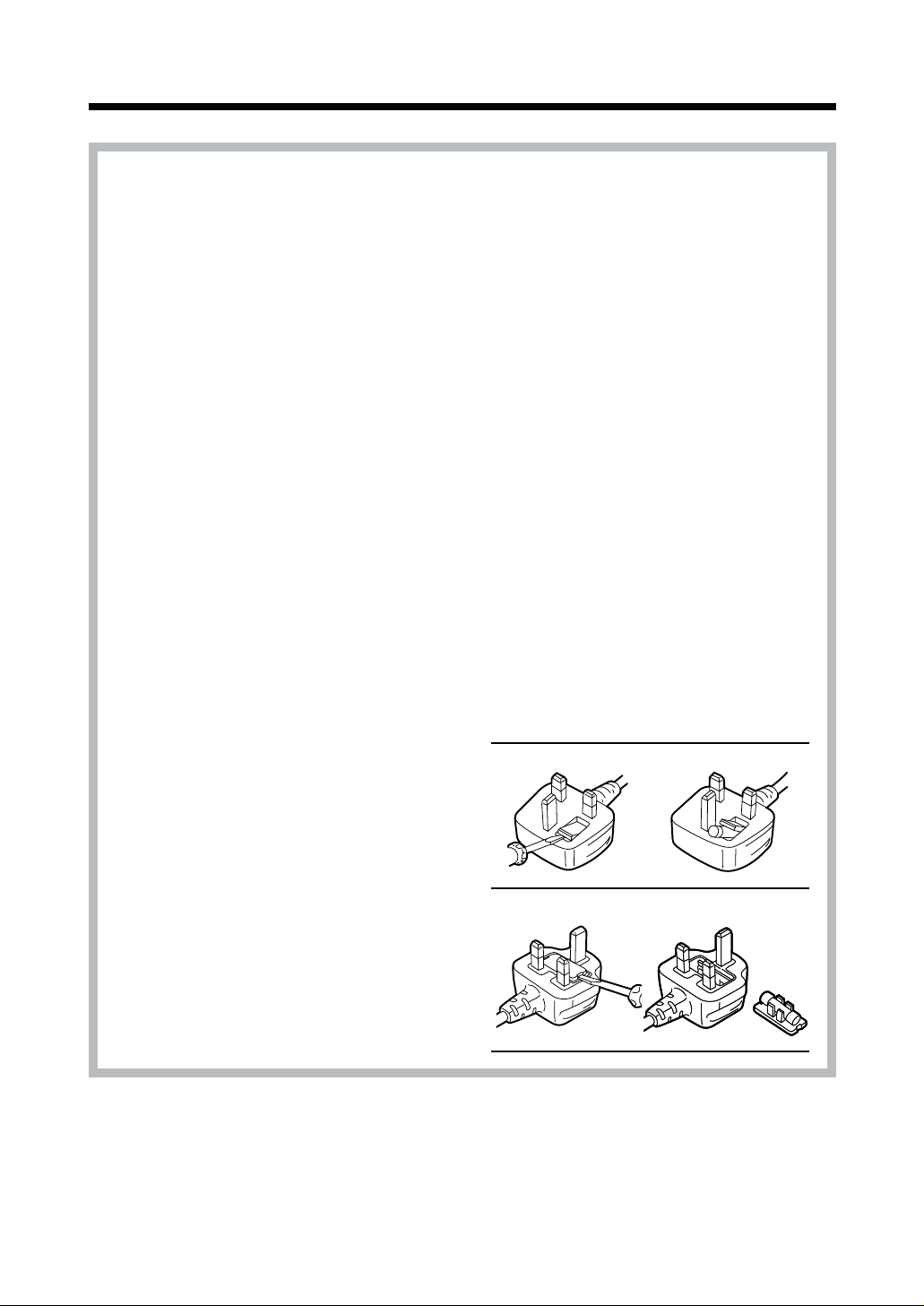
How to Replace the Fuse
≥ There are two types of the AC mains lead
assembly:
A and B as shown below.
1 Open the fuse compartment with a
screwdriver.
2 Replace the fuse and fuse cover.
TYPE A
12
TYPE B
12
6
Page 7
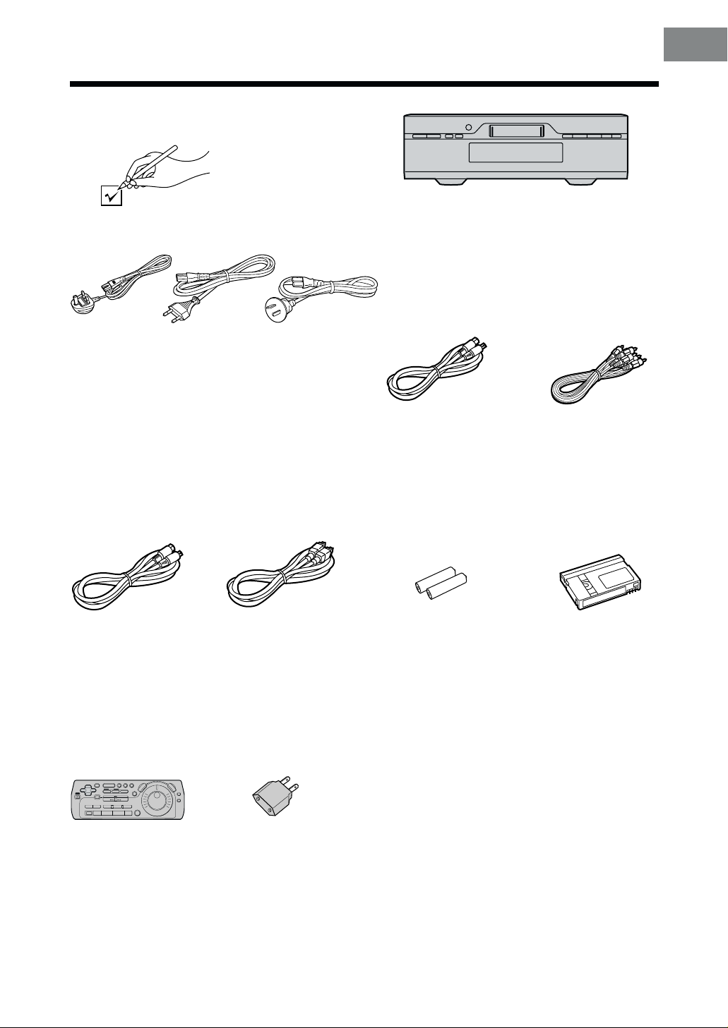
Check List
Check that you have the accessories and items shown below.
Before Use
1. VJA0733-C
VJA0940
VJA1022
[See a leaflet.]
∆∆
∆
∆∆
AC mains leads (3 pcs.)
∆∆
∆
∆∆
Edit cable (1 pc.)
VJA1109 or VJA0787
2. VJA1039
VJA0664-1
VJA0664-1A
VJA1023
3. VJA0754
VJA1068
∆∆
∆
∆∆
DV cable (1 pc.)
VJA1012
∆∆
∆
∆∆
S-Video cable (1 pc.)
VJA0658-A or VJA0748
∆∆
∆
∆∆
Batteries for the Editing
Controller
(2 pcs.)
R6 type
∆∆
∆
∆∆
AV cables (1 pc.)
VJA0788, VJA1062,
VJA0788-B or VJA0788-D
∆∆
∆
∆∆
Digital Video Head
Cleaner (1 pc.)
VFK1451
∆∆
∆
∆∆
Editing Controller
(1 pc.)
EUR571507
∆∆
∆
∆∆
AC Plug Adaptor
(1 pc.)
VJP2974
∆∆
∆
∆∆
Guarantee Card
VQA0650-1
VQA0335
VQA0380
∆∆
∆
∆∆
Operating Instructions
VQT8649 (English)
VQT8650 (German)
VQT8651 (French)
VQT8652 (Italian)
VQT8653 (Chinese)
7
Page 8
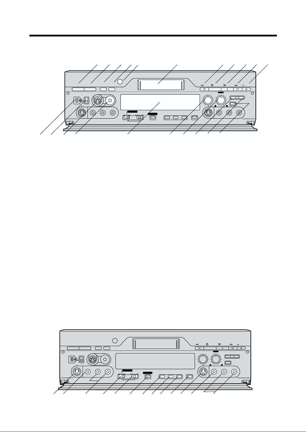
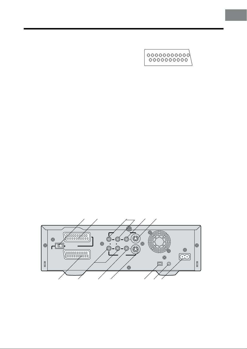
Controls and Connection Sockets
This section gives a detailed explanation of the function of each button, switch and connection socket.
2
3
AUDIO
1
2
EJECT
<
EDIT 8mm
VIDEO
STEREO
OUT
SERECT
L/MONO– AUDIO – R
EDIT CONTROL
RECORDER
PLAYER
PRINTER/
D.STILL PICTURE
16
PASSIVE
12
13
14
AV4
IN
15
Í / I
¥
DV 2
DV SELECT
S-VIDEO
Front
01 VCR-ON/OFF button (]/I) [R16]
02 EJECT button (<) [R12]
03 STEREO SELECT button [R17,41,42,45,51]
04 AUDIO OUT button [R22]
05 Infra-red receiver window
06 Cassette compartment
07 Rewind button (6) [R15]
08 STOP button (∑) [R15,16]
09 PLAY button (!) [R15]
10 Fast Forward button (5) [R15]
;;
11 PAUSE/SLOW button (
12 DV Input/Output socket [DV2 (¥)] [R28,30]
13 DV SELECT (DV1/DV2) switch [R29,31]
14 EDIT socket [R19,28,30,32]
15 8mm socket [R34]
16 Display
17 AUDIO REC LEVEL knob [R17]
18 AUDIO MIX knob [R17]
19 STILL ALBUM button [R38]
DD
;/
D) [R15,16]
;;
DD
4
5
8mm
EDIT
DV
MIXING EDIT
6
SP/LP TBC 3D DNR PRINT
19
18
17
REW STOP
AUDIO REC LEVEL
010
S-VIDEO
20
STEREO1
AUDIO MIX
STEREO1 STEREO2
VIDEO
21
71
PLAY
100
8119
STILL
ALBUM
INPUT SELECT
L– AUDIO – R
FF
¥
REC/OTR
PAUSE
AV4
OUT
10
20 REC/OTR button (¥) [R16]
21 INPUT SELECT button [R27–35]
22 S-Video Input socket [S-VIDEO IN (AV4)]
[R28,30,32,34]
23 Video Input socket [VIDEO IN (AV4)]
[R28,30,32,34]
24 Audio Input socket [AUDIO IN (AV4)]
[R28,30,32,34]
25 Edit Mode switch [R19,20,29–35]
26 Edit Terminal switch[R19,20,29–35]
27 MIXING EDIT button [R42]
28 SP/LP button [R16,27]
29 Time Base Corrector button (TBC) [R17]
30 3 Dimentional Digital Noise Reduction button
(3D DNR) [R17]
31 PRINT button [R19]
32 S-Video Output socket [S-VIDEO OUT (AV4)]
[R19]
33 Video Output socket [VIDEO OUT (AV4)]
34 Audio Output socket [AUDIO OUT (AV4)]
STEREO
22
23
Í / I
<
EJECT
¥
DV 2
DV SELECT
1
2
AV4
IN
S-VIDEO
VIDEO
24
AUDIO
SERECT
EDIT 8mm
L/MONO– AUDIO – R
25
OUT
RECORDER
PLAYER
PRINTER/
D.STILL PICTURE
26
EDIT CONTROL
8mm
PASSIVE
EDIT
DV
28 29 30 31
27
MIXING EDIT
SP/LP TBC 3D DNR PRINT
32
33
REW STOP
AUDIO REC LEVEL
010
S-VIDEO
34
STEREO1
AUDIO MIX
STEREO1 STEREO2
VIDEO
PLAY
100
STILL
ALBUM
INPUT SELECT
L– AUDIO – R
¥
FF
REC/OTR
PAUSE
AV4
OUT
8
Page 9
Front (Explanation)
VCR-ON/OFF button (
]]
]/I)
]]
Press to switch the VCR from on to standby mode or
vice versa. In standby mode, the unit is still connected
to the mains.
Edit Terminal switch
By connecting a video movie camera or VCR with an
EDIT socket via an Edit cable, various kinds of editing
functions can be performed more quickly and
efficiently between two VCRs or between a VCR and
a video movie camera.
DV Input/Output socket [DV1/DV2(¥)]
To connect the DV cable to digital video equipment
with iEEE 1394-1995.
“¥” is the logo marked on products conforming with
the “i.LINK” specifications. For further details on the
DV terminal, refer to the Glossary of Terms on page
58.
Edit Mode switch
PLAYER: When this VCR is used as the playback
VCR during editing operations.
RECORDER: When this VCR is used as the recording
VCR during editing operations.
≥ Normally set at this position.
PASSIVE: When operating this VCR using another
VCR or an editing controller.
AV1 21-pin Scart socket [AV1 (TV)]
This 21-pin scart terminal carries input and output
signals for both picture and sound. TV sets equipped
with a similar socket can be connected here.
The scart terminal is also called “Peritel”, “Euro
Connector” or “Euro AV”.
1 3 5 7 9 11 13 15 17 19
21
2 4 6 8 10 12 14 16 18 20
NORMAL (AV1/AV2) S-VIDEO (AV1)
01 AUDIO OUTPUT 01 AUDIO OUTPUT
CH2 (R) CH2 (R)
02 AUDIO INPUT 02 AUDIO INPUT
CH2 (R) CH2 (R)
03 AUDIO OUTPUT 03 AUDIO OUTPUT
CH1 (L) CH1 (L)
04 AUDIO GND 04 AUDIO GND
05 BLUE GND 05 No connection
06 AUDIO INPUT 06 AUDIO INPUT
CH1 (L) CH1 (L)
07 BLUE 07 No connection
08
SWITCHING VOLTAGE
09 GREEN GND 09 No connection
10 Connection 10 Connection
(Only when NV-DV2000 is off)
11 GREEN 11 No connection
12 No connection 12 No connection
13 RED GND 13 C OUT GND
14 BLANKING GND 14 No connection
15 RED 15 C OUT
16 BLANKING 16 No connection
17 VIDEO OUTPUT GND 17 Y OUT GND
18 VIDEO INPUT GND 18 VIDEO INPUT GND
19 VIDEO OUTPUT 19 Y OUT
20 VIDEO INPUT 20 VIDEO INPUT
21 GND 21 GND
08 SWITCHING VOLTAGE
Caution: RGB reservation for only E/E operation when
connecting the Pay TV decoder.
Before Use
35
36
(TV)
NORMAL
40
AV1
S-VIDEO OUT
AV2(EXT
41
)
42
MONITOR OUT
R AUDIO L
43
Rear
35 NORMAL/S-VIDEO OUT switch for AV1 only [R13]
36 AV1 21-pin Scart socket [AV1 (TV)] [R13,14]
37 Audio Monitor Output sockets [AUDIO OUT (AV3)]
[R13,14,30]
38 Video Monitor Output socket [VIDEO OUT (AV3)]
[R13,30]
39 S-Video Output socket (S-VIDEO OUT) [R13,19]
40 AV2 21-pin Scart soc ket [AV2 (EXT)] [R14]
37
VIDEO S-VIDEO
AV3 IN
44
38
45
39
¥
DV1
46
SECTEUR
DIGITAL STILL
PICTURE OUT
AC INT
T
41 Audio Input sockets [AUDIO IN (AV3)]
42 Video Input socket [VIDEO IN (AV3)]
43 S-Video Input socket [S-VIDEO IN (AV3)]
44 DV Input/Output socket [DV1(¥)]
45 DIGITAL STILL PICTURE OUT socket [R20]
46 AC Input socket (AC IN) [R13]
9
Page 10
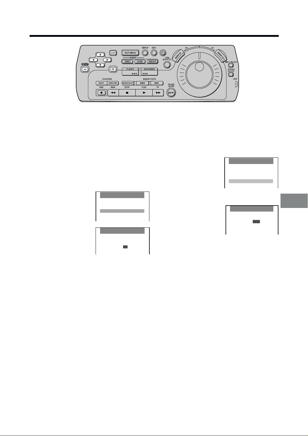
Editing Controller
2
DIGITAL VCR
10
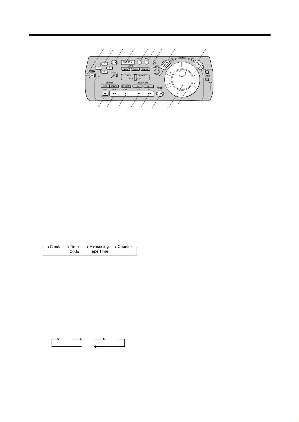
01 SET UP button
To make the SET UP screen appear on the TV
screen. When the SET UP screen is displayed, use
this button to return to the previous screen.
02 CURSOR button (
To make selections from the SET UP or EDIT
MENU screen. (When the SET UP or EDIT MENU
screen is displayed.)
03 EXIT button
To exit the SET UP or EDIT MENU screen.
04 EDIT MENU button
To make the EDIT MENU screen appear on the TV
screen, and to return to the previous screen. This
button is also used to stop editing functions using
the EDIT MENU screen.
05 DISPLAY button [R16]
To change the VCR display indication as follows:
34213421
3421)
34213421
11
12
3
4
13
61
57
8
14 15 16
10 REC button (¥) [R16,39,40]
To start recording.
11 Rewind button (6) [R15]
In the stop mode: To rewind the tape.
In the playback mode: To search backward for a
In the rewind mode: To view the video.
12 STOP button (∫) [R15,16]
To stop playback or recording.
13 PLAY button (1) [R15]
To start playback. “!”is lit during playback.
14 Fast Forward button (5) [R15]
In the stop mode: To fast forward the
In the playback mode: To search forward for a
In the fast forward mode: To view the video.
9
scene.
“&”is lit during rewind.
tape.
scene.
“%” is lit during fast
forward.
Note:
The VCR display cannot be switched between the
Time code display and the tape counter display while
editing is in progress.
06DATE button
When pictures are recorded using the NV-DV2000
or a Panasonic Digital Video Camera, the date and
time of the recording are automatically recorded
onto the tape’s sub code track.
This button is used to select the information to be
displayed on the On Screen Display.
Date
Time
07 VCR-ON/OFF button (Í) [R16]
08 MARK IN button [R46 –51]
To set edit star t points for Programme Editing.
09 MARK OUT button [R46–51]
To set edit end points for Programme Editing.
10
Date
OFF
Time
15 PAUSE/SLOW button (;/D) [R15]
During playback:
≥ When pressed once:Still picture. “+” is lit.
≥ When pressed for 2 seconds or more:
Slow playback. “-” is lit.
During recording: To pause recording.
16 Jog Dial/Shuttle Ring [R15,39– 51]
Jog Dial (inner dial):
Operate after pressing JOG/SHUTTLE to switch
to the Jog/shuttle mode.
To locate any desired field with utmost precision.
Shuttle Ring (outer ring):
Operate after pressing JOG/SHUTTLE to switch
to the Jog/shuttle mode.
To adjust playback speed backward or forward.
Page 11
17
DIGITAL VCR
25 26 27 28 29 30 31
24
18 19
20
21
22
17
23
Before Use
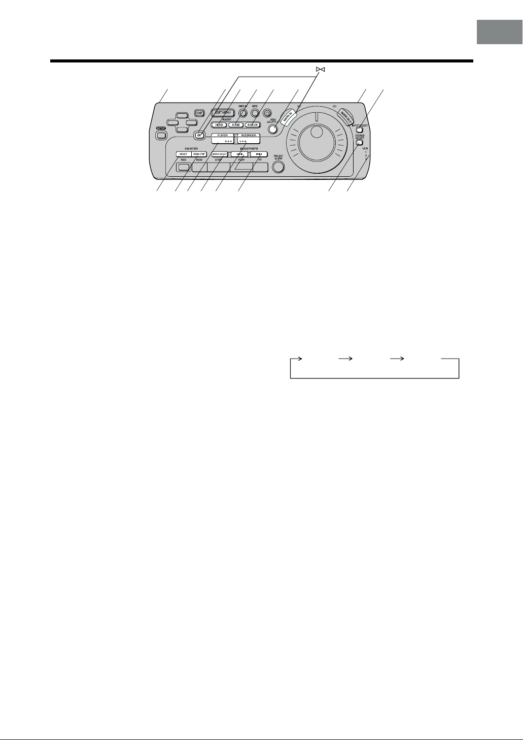
17 Infra-red Transmitter window
18 OK button
To start Manual editing and to store the selection
on the SET UP or EDIT MENU screen.
19 VIDEO INSERT button [R39,41]
For the Video Insert function and the AV Inser t
function.
20 AUDIO INSERT button [R39,41]
For the Audio Insert function and the AV Inser t
function.
21 AUDIO DUB button [R39,41,42]
For the Audio Dubbing function or the Audio Mixing
function.
22 JOG/SHUTTLE button and lamp [R15,39–51]
To switch to the Jog/Shuttle mode. When the button
is pressed, it lights and the VCR enters the Jog/
Shuttle mode.
In the stop mode: Still picture (Jog/Shuttle mode).
During playback: Still picture (Jog/Shuttle mode).
23 INPUT SELECT button [R27 –35]
To select the A1, A2, A3, A4 or DV IN (DV1 or DV2)
external recording source.
24 COUNTER RESET button [R18]
To reset the tape counter (elapsed time) to
“0:00.00”.
≥ The tape counter is automatically reset to
“0:00.00”. when a video cassette is inserted.
≥ It is not possible to reset the Time code to
“0h00m00s00f ” using COUNTER RESET.
28 RECORDER button [R43–51]
To operate this VCR as the recording unit for
editing.
29 INDEX/PHOTO buttons [R18]
For the index/photoshot index search function.
30 STEREO SELECT button [R17,41,42,45,51]
To select the audio track (STEREO1 audio and/or
STEREO2 audio) on a tape which was recorded in
the 12bit audio mode. During playback, each time
the button is pressed, the sound changes as
follows:
STEREO1
≥ The audio track cannot be selected during the
playback of a tape recorded in the 16bit audio
mode.
≥ When INPUT SELECT is set to DV1 or DV2, the
audio track can be selected by STEREO
SELECT at any time: it does not have to be
during playback.
31 VCR1/2/3 switch
Set the switch on the side panel of the editing
controller to the appropriate position when more
than two or three Panasonic VCRs is being used.
VCR1: Select this position on both the
VCR2: Select this position when using two
VCR3: Select this position when using
STEREO2
VCR and editing controller for
normal use with one VCR.
Panasonic VCRs.
three Panasonic VCRs.
STEREO1
STEREO2
(MIX)
25 COUNTER ZERO STOP button [R18]
To use the zero stop function at the tape counter
display.
26 PLAYER button [R43–51]
To operate this VCR as the playback unit for
editing.
27 SEARCH SELECT button [R18]
To search for a recorded programme using the
index/photoshot index search.
!" Child Lock buttons [R12]
To set the child lock function when you keep
pressing OK and MARK IN for more than five
seconds.
11
Page 12
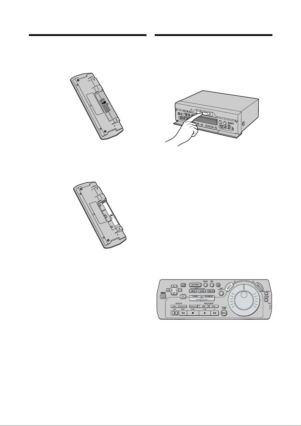
Inserting the Cassette/
Editing Controller Setup
Installing the Batteries
1 To remove the cover, slide it in the direction of the
arrow while pressing down.
7
8
2 Load the batteries with their polarity ( + and -)
aligned correctly.
d
e
d
e
3 Slide the cover back on.
Child Lock Function
Be sure to insert the cassette with the window side
facing upwards until it is taken into the VCR.
Press EJECT and remove the cassette from the video
unit.
Child Lock Function
When you do not want other people to operate the VCR.
Holding down OK and MARK IN until “!" ” and “hold”
appears more than 5 seconds in the VCR display will
deactivate all buttons. Any external commands will not
be processed by the VCR.
To cancel this function, repeat the same procedure until
“!"” and “hold” disappears.
≥ If a button is pressed while the Child Lock function is
on, “!" ” and “hold” appears in the VCR display.
≥ When the power is disconnected, the Child Lock
function is automatically cancelled after backup time.
Power Source for the Editing Controller
The editing controller is powered by 2 AA, UM3 or R6
size batteries. The life of the batteries is about one year,
although this depends on the frequency of use.
Precautions for Battery Replacement
≥ Load the new batteries with their polarity (+ and -)
aligned correctly.
≥ Do not apply heat to the batteries, or an internal
short-circuit may occur.
≥ If you do not intend to use the editing controller for a
long period of time, remove the batteries and store
them in a cool, dry place.
≥ Remove spent batteries immediately and dispose of
them.
≥ Do not use an old and a new battery together, and
never use an alkaline battery with a manganese
battery.
≥ Do not use rechargeable batteries.
12
DIGITAL VCR
Page 13
MONIT
OR OUT
R A
UDIO L
C IN
NORMAL
MONIT
R A
UDIO L
PICTURE OUT
C IN
NORMAL
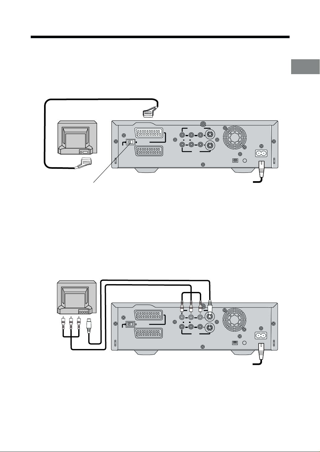
Connections Using a 21-pin Scart Cable/ Connections Using an S-Video Cable
Connections Using a 21-Pin Scart Cable
The VCR send signals to the TV via a 21-pin scart cable (not supplied).
Perform the connections shown in the figure below.
Set NORMAL/S-VIDEO OUT to the S-VIDEO OUT when connecting the VCR to a TV set equipped with a 21-pin
Euro-AV Connector with pins for separate Y/C signal input.
TV Set (Not supplied)
(TV)
NORMAL
AV1
S-VIDEO OUT
AV2(EXT
)
R A
MONIT
UDIO L
OR OUT
VIDEO S-VIDEO
AV3 IN
¥
DV 1
SECTEUR
DIGITAL STILL
PICTURE OUT
AC IN
T
T
Setting Up
NORMAL/S-VIDEO OUT switch
Connections Using an S-Video Cable
The VCR send signals to the TV via an S-Video cable (supplied).
Perform the connections shown in the figure below.
Separate Y/C signals can be obtained using the S-Video cable.
TV Set (Not supplied)
(TV)
AV1
S-VIDEO OUT
NORMAL
)
AV2(EXT
R A
MONIT
UDIO L
OR OUT
VIDEO S-VIDEO
AV3 IN
To mains supply
DIGITAL STILL
¥
DV 1
PICTURE OUT
AC IN
SECTEUR
T
T
To mains supply
13
Page 14
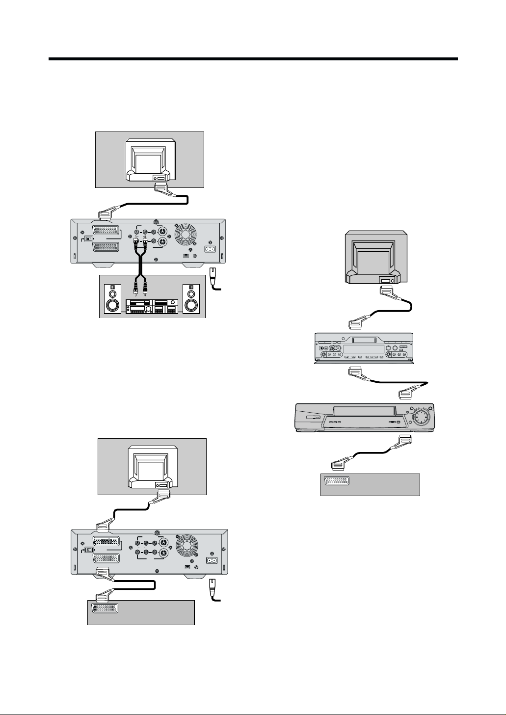
Connection to a Stereo Amplifier/ Connection to a Decoder
Connection to a Stereo Amplifier
In addition to the connections described on the previous
page, connect the MONITOR OUT (AV3 OUT) sockets
to the Amplifier using an AV cable.
TV
(Not supplied)
(TV)
NORMAL
S-VIDEO OUT
AV1
AV2(EXT
)
MONITOR OUT
R AUDIO L
VIDEO S-VIDEO
AV3 IN
Stereo Amplifier
(Not supplied)
AC INT
SECTEUR
T
DIGITAL STILL
¥
PICTURE OUT
DV 1
Note:
¡ If the TV set is provided with an RGB-compatible
connector, connect the 21-pin Scart cable from the
VCR to this connector. Use the fully-wired 21-pin
Scart cable for connecting the TV set and VCR and
for connecting the VCR and decoder.
Connections for the “Q Link” Function of
the other TV, VCR and Decoder
The NV-DV2000 does not have the “Q Link” function, but
the connections below link the NV-DV2000 to a TV, a
VCR with tuner and a decoder so that the “Q Link”
function may work.
We recommend this connection for advanced users.
TV
(Not supplied)
AV1
Connection to a Decoder
In addition to the connections described on the previous
page, connect the AV2 socket to the decoder using a
21-pin Scart cable.
TV
(Not supplied)
(TV)
NORMAL
S-VIDEO OUT
AV1
AV2(EXT
)
MONITOR OUT
R AUDIO L
VIDEO S-VIDEO
AV3 IN
Decoder
(Not supplied)
AC INT
SECTEUR
T
DIGITAL STILL
¥
PICTURE OUT
DV 1
AV2
Other VCR (Not supplied)
AV1
AV2
Decoder (Not supplied)
Hint:
Turn off the NV-DV2000 so that the “Q Link”, “DATA
LOGIC”, “NEXTVIEWLINK”, “Easy Link”, “Megalogic”,
“SMART LINK” or other logo functions of other TV, VCR
and decoder may work.
The following “Q Link”, “DATA LOGIC”,
“NEXTVIEWLINK”, “Easy Link”, “Megalogic” or “SMART
LINK” functions are available.
≥ Preset Download
≥ Direct TV REC
≥ TV/VCR Auto Power On
14
Page 15
Playback
10
DIGITAL VCR
6
3
Preparation
≥ Insert a recorded cassette
tape. [R12]
2
1
4,
REW STOP
AUDIO REC LEVEL
5
0 10
RINT
S-VIDEO VIDEO
STEREO1
AUDIO MIX
ST1 ST2
PLAY
STILL
ALBUM
INPUT SELECT
100
L – AUDIO – R
FF PAUSE
¥
REC/OTR
AV4
OUT
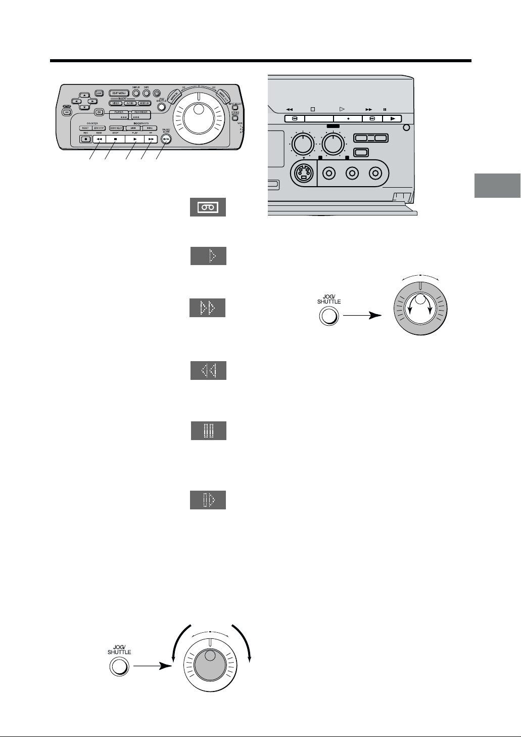
Operations
1 Press 1 (PLAY) to start
playback.
2 Press 5 (FAST FORWARD)
for cue playback.
≥ Press 1 (PLAY) to
change back to normal
playback.
3 Press 6 (REWIND) for
review playback.
≥ Press 1 (PLAY) to
change back to normal
playback.
4 Press ;/D (PAUSE/SLOW) to
view a still picture.
≥ Press 1 (PLAY) or
;/D (PAUSE/SLOW) to
continue normal
playback.
5 Keep ;/D (PAUSE/SLOW)
pressed for 2 seconds or more to
view a slow motion picture.
≥ Press 1 (PLAY) to continue normal playback.
6 Press ∫ (STOP) to stop
the picture.
To Locate the Desired Picture Exactly
1Press JOG/SHUTTLE on the Editing controller.
≥ The button on the editing controller is lit.
2Turn Jog dial.
QP
To View the Video During Fast Forward or
Rewind
Keep D (FAST FORWARD) pressed during fast
forward.
Keep C (REWIND) pressed during rewind.
Convenient Automatic Functions
Automatic Playback
When a cassette with the opened record prevention tab
is inserted, the VCR starts playback automatically.
VCR-off Playback
When the VCR is off, an inserted cassette can be
played back by pressing 1 (PLAY).
Automatic Rewinding
When the tape reaches the end during recording or
playback, it will automatically be rewound to the
beginning.
≥ During OTR, this function will not work.
Playback and Recording
To Change the Playback Speed
1Press JOG/SHUTTLE on the Editing controller.
≥ The button on the editing controller is lit.
2Rotate Shuttle Ring.
QP
Notes:
≥ If you keep 5 (FAST FORWARD) or 6 (REWIND)
pressed in step 2 or 3, search playback is activated
while the button is pressed, and operation returns to
normal playback when the button is released.
≥ Cue, review or slow playback will be automatically
cancelled after 10 minutes, and still playback after
5 minutes.
¡ When using the Editing controller for remote control:
In order to conserve battery power, JOG/SHUTTLE
turns off after 30 seconds.
15
Page 16
10
Recording
DIGITAL VCR
SETUP
COUNTER
RESET
ZERO STOP
REC REW STOP PLAY FF
STEREO
SERECT
Í / I <
EJECT
EDIT 8mm
¥
DV2
DV SELECT
1
2
AV4
IN
L/MONO– AUDIO – R
VIDEO
S-VIDEO
DATE
DISPLAY
EDIT MENU
EXIT
INSERT
AUDIO
AUDIO DUB
VIDEO
PLAYER
SEARCH SELECT
RECORDER
PLAYER
PRINTER/
D.STILL PICTURE
EDIT CONTROL
PASSIVE
RECORDER
INDEX/PHOTO
8mm
EDIT
MIXING EDIT
DV
OK
AUDIO
OUT
N
I
K
R
A
JOG/
M
SHUTTLE
PAUSE/
SLOW
SP/LP TBC 3D DNR PRINT
QP
REW STOP
AUDIO REC LEVEL
010
S-VIDEO
M
A
R
K
O
U
T
PLAY
STEREO1
STILL
AUDIO MIX
ALBUM
INPUT SELECT
100
ST1 ST2
L– AUDIO – R
VIDEO
Preparations
≥ Insert a video cassette with the
closed record prevention tab.
≥ If it has already been inserted,
press VCR-ON/OFF Í/I to turn
the VCR on.
≥ Press INPUT SELECT to select
A1-A4.
Press INPUT SELECT so that
DV1 or DV2 after sliding DV
SELECT to 1 or 2, is selected.
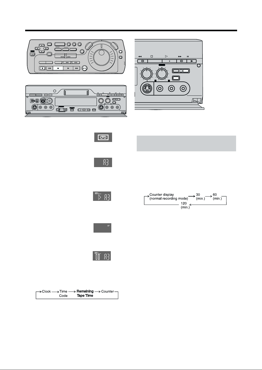
Operations
1 Press
¥¥
¥ (REC) or
¥¥
¥ ¥
¥ (REC/OTR) to start
¥ ¥
REC
recording.
2 Press ∫ (STOP) to stop
recording.
To Select the Desired Tape
Speed
Press SP/LP before recording.
To Pause Recording
Press ;/D (PAUSE/SLOW) during
recording.
Press it again to continue recording.
REC
To Display the Remaining Tape Time
Press DISPLAY repeatedly until the Remaining Tape
Time appears on the VCR display.
≥ The remaining tape time may not be displayed
correctly for some tapes.
INPUT SELECT
STEREO
SELECT
FF PAUSE
¥
REC/OTR
VCR
1
2
3
REW STOP
AUDIO REC LEVEL
0 10
S-VIDEO VIDEO
AV4
OUT
STEREO1
AUDIO MIX
ST1 ST2
PLAY
STILL
ALBUM
INPUT SELECT
100
L – AUDIO – R
FF PAUSE
¥
REC/OTR
AV4
OUT
One-Touch Recording (OTR)
This function only works using REC/OTR on
the VCR main unit.
After you start recording, you can use this function to
stop recording automatically when the selected
recording duration is finished (useful for recording when
you are out). Simply set the recording duration by
pressing
The duration indicated on the VCR display changes by
pressing
Preparation
Insert a video cassette with the closed record
prevention tab.
Operations
1 Set the video source which is to be recorded, and
2 Press
Notes:
≥ When the tape reaches the end during OTR, the VCR
≥ To stop OTR at any time, press ∫ (STOP) or VCR-
¥¥
¥ (REC/OTR) repeatedly.
¥¥
¥¥
¥ (REC/OTR) as follows:
¥¥
start recording.
¥¥
¥ (REC/OTR) repeatedly to select the
¥¥
desired recording duration.
≥ The VCR will automatically switch off when OTR
is completed. To turn the VCR on again, press
VCR-ON/OFF Í/I.
will turn itself off.
ON/OFF Í/I.
Notes:
≥ The tape speed during fast forward, rewind and index
search is automatically regulated according to the
remaining amount of tape. In these cases, the tape
counter and the time code display may stop
temporarily.
≥ Recording pause will be automatically cancelled after
16
5 minutes.
Page 17
Other Playback and Recording Functions
STEREO
AUDIO
SERECT
Í / I <
¥
DV2
AV4
IN
S-VIDEO
OUT
EJECT
EDIT 8mm
DV SELECT
1
2
VIDEO
SP/LP TBC 3D DNR
L/MONO-AUDIO-R
RECORDER
PRINTER/
D.STILL PICTURE
EDIT CONTROL
8mm
PLAYER
PASSIVE
EDIT
MIXING EDIT
DV
SP/LP TBC 3D DNR PRINT
REW STOP
AUDIO REC LEVEL
010
S-VIDEO
PLAY
FF PAUSE
STEREO1
STILL
AUDIO MIX
ALBUM
¥
REC/OTR
INPUT SELECT
100
ST1 ST2
L - AUDIO - R
VIDEO
3D DNR Functions
3D DNR is the 3-Dimensional Digital Noise Reduction
Function. [R58]
To Ensure High Playback Picture Quality
(PB 3D DNR Function)
To set the 3D DNR mode for playback, proceed as
follows.
≥ Press the 3D DNR button before or during playback
to activate the PB 3D DNR function, so that the “PB
DNR” indication appears on the VCR display.
≥ We recommend that you leave this function activated
for normal use of the VCR.
≥ When you play back a tape that was recorded with
REC DNR function on, set “PB DNR” to off.
≥ See [R24] to set the level of “PB 3D DNR” function.
≥ In the initial settings, “PB DNR” is “on.”
≥ If afterimage occurs, turn “PB DNR” off.
To Record in the High Picture Quality
(REC 3D DNR Function)
To set the 3D DNR mode for recording, proceed as
follows.
≥ Press the 3D DNR button before recording. The
“REC DNR” indication appears on the VCR display.
≥ When you cannot ensure high playback picture
quality, press the 3D DNR button to cancel the “REC
3D DNR” function, so that the “REC DNR” indication is
turned off.
≥ Press the INPUT SELECT button to select A1–A4.
Each time the 3D DNR button is pressed, the
indication changes on the VCR display as follows.
REC DNR
PB DNR
OFF
To Ensure a Stable and Shake-Free
Recording Picture (TBC)
(For Recording Only) [R57]
TBC stands for Time Base Corrector.
When the tape movement is unstable during recording,
the playback picture may shake from side to side and
the picture may become distorted.
Activating the Time Base Corrector in a case lik e this
stabilize the picture and reduces the shaking.
≥ Press the TBC button before recording to activate
“TBC” function so that the “TBC” indication appears
on the VCR display.
≥ We recommend that you leave this function activated
AV4
OUT
for normal use of the VCR.
≥ When you cannot ensure high playback picture
quality, press the TBC button to cancel “TBC” function
so that the “TBC” indication is turned off.
≥ Only when A1–A4 is selected by pressing the INPUT
SELECT button, “TBC” function will be elected.
This function has an effect only for tapes on which
analogue signals from A1-A4 have been recorded.
However, on the TV screen, you cannot confirm the
effect of this function during recording.
≥ In the initial settings, “TBC” is “ON.”
To Manually Adjust the Audio Recording Level
Under normal circumstances, this VCR adjusts the
recording level to prevent sound distor tion due to peaks.
However, if you want to manually adjust the audio
recording level or if sound distortion appears when you
confirm the audio output, perform the operation steps
below before you start the actual recording.
Adjust the recording sound with the AUDIO REC LEVEL
knob.
≥ Press the knob once so that it pops out. (To close the
front door, press the knob into the VCR.)
≥ Turn the knob so that the audio level indication on the
VCR display is not “OVER”.
dB -¶ 30 20 10 5 0 OVER
L
ST1 2
ST1 2
l l l l l l l l
R
l l l l l l l l l l l l l l l
≥ This function has an effect only for tapes on which
analogue signals from A1-A4 have been recorded.
You cannot adjust the audio level from DV input.
(However, you can adjust the audio level by
connecting to the external input socket.)
To Change the Audio Mix Sound Balance
Select “Mix sound” during playback in the 12 bit audio
mode, then turn the AUDIO MIX knob to adjust the
balance.
≥ Press the knob once so that it pops out. (To close the
front door, press the knob into the VCR.)
≥ Turn the knob to the left to increase the “ST1” sound,
or to the right to increase the “ST2” sound.
The audio track cannot be selected during the
playback of a tape recorded in the 16 bit audio mode.
≥ Use the STEREO SELECT button to select the audio,
and then adjust the balance.
dB -¶ 30 20 10 5 0 OVER
L
ST1 2
ST1 2
l l l l l l l l
R
l l l l l l l l l
Playback and Recording
17
Page 18
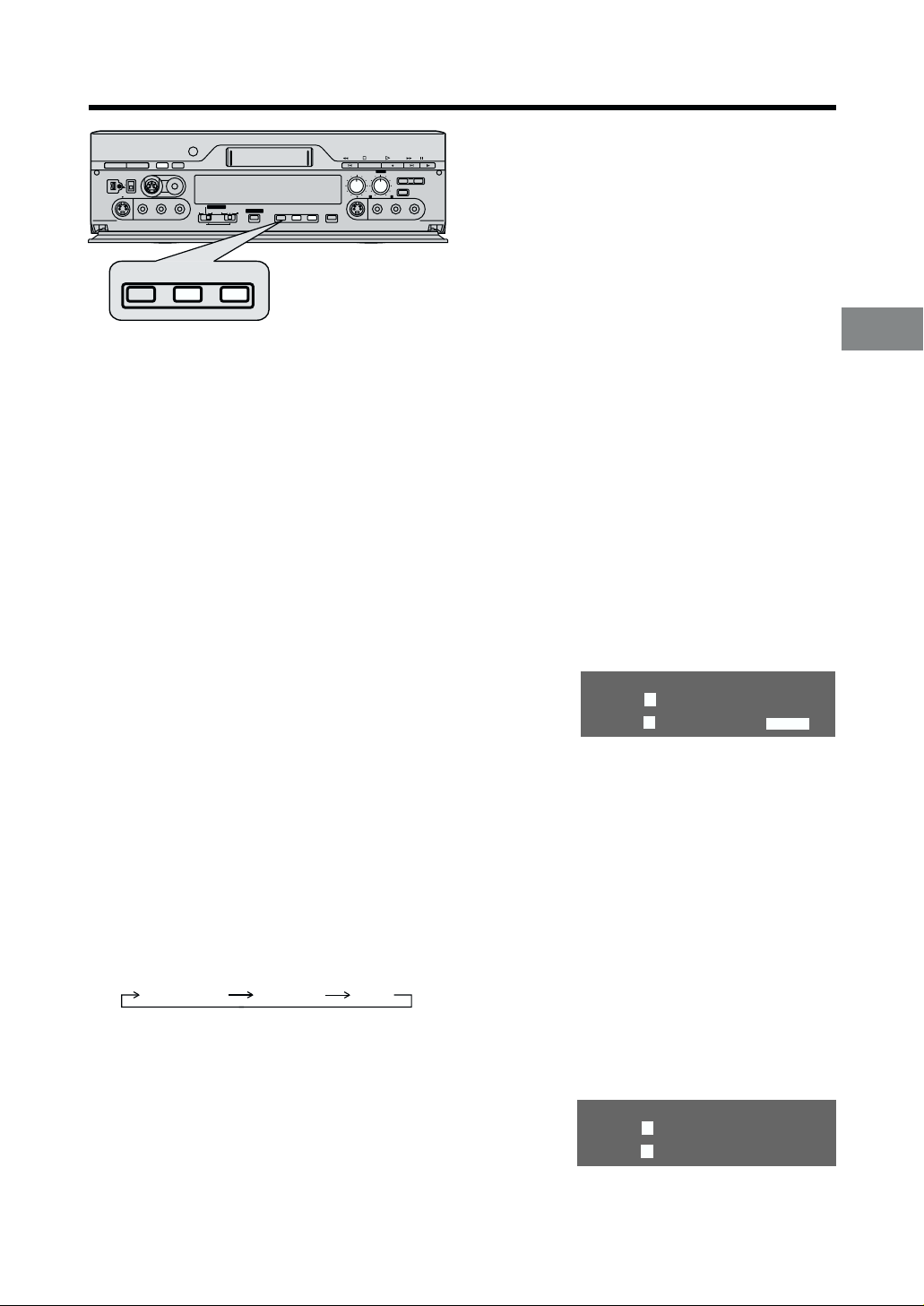
Search Functions
DIGITAL VCR
Index Search System
It is easy to find the beginning of each recording
because a special index signal is recorded at the start
of each recorded segment on the tape.
For example:
Searching for the 2nd recorded segment in the forward
direction.
1 Press SEARCH SELECT so that “– –” appears on the
VCR display.
(This operation is performed while the VCR is in the
stop mode or normal playback mode.)
2 Press INDEX/PHOTO 9 twice.
≥ Normal playback now commences.
To stop the operation at any time
Press ∫ (STOP).
≥ After finding the specific recorded segment, playback
starts automatically.
≥ For the reverse direction, press INDEX/PHOTO :.
≥ Up to 20 index signals can be searched for in either
direction.
≥ When the opposite INDEX/PHOTO is pressed, the
number shall be decreased until 1 is reached.
≥ The figure on the display is reduced by 1 each time
an index signal is located.
≥ The index search function can only work correctly if
the index signals are spaced at least 5 minutes apart.
≥ Repeat the procedure if the index signal for the
specified number is not found.
Recording Index Signals
Index signals are recorded in the following cases.
≥ When a recording is started by pressing
OTR).
≥ When
¥¥
¥ (REC) on the editing controller is pressed
¥¥
during recording.
¥ ¥
¥ (REC/
¥ ¥
Photoshot Index Search System
Photoshot index signals are automatically recorded
when a Panasonic Digital Video Camera is used for
photo shot shooting. Photo shot images are searched
using these signals, and when such an image is
located, the image is played back as a still picture.
For example:
Searching for the 2nd photo shot image in the forward
direction.
1 Press SEARCH SELECT so that “P ––” appears on
the VCR display.
2 Press INDEX/PHOTO 9 twice.
≥ The image to be viewed
will be found.
≥ For the reverse direction, press INDEX/PHOTO :.
≥ Any of up to 20 images ahead on the tape can be
designated.
≥ It may not be possible to search for a particular image
properly if photo shot images have been recorded
continuously.
≥ At every press of the corresponding button, the tape
is fast-forwarded or rewound to the next still picture
recorded in the Photoshot Mode.
≥ During playback, after reaching the still picture, the
still picture is played back continually together with
the sound (only for approx. 4 seconds).
To return to a specified scene
(zero stop function)
1 Press RESET to set the counter to 0:00.00.
2 After playback, press ZERO STOP in the stop mode.
≥ The tape will be rewound or fast forwarded to
0:00.00 approximately.
≥ During Time code display, this function will not
work.
18
Page 19
PRINTER/
.STILL PICTURE
RECORDER
ASSIVE
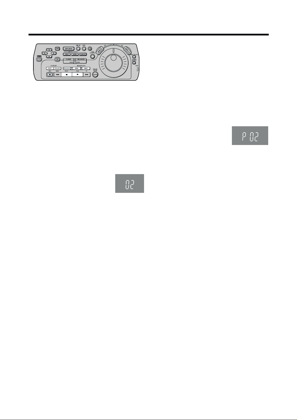
Using the VCR with a Video Printer
Still pictures can easily be printed out when the VCR is connected to a Panasonic video printer equipped with an
EDIT socket.
TV (Not supplied)
Video IN
Video OUT
EDIT Socket
Video Printer (Not supplied)
S-Video IN
EDIT
RECORDER
PLAYER
PASSIVE
EDIT
DV
PRINTER/
D.STILL PICTURE
Preparation
≥ Connect a Video Printer to this VCR as shown.
Video Printer:
1 Turn the Video Printer on.
2 Perform the necessary settings on the Video Printer
according to the input signal.
VCR:
3 Turn the VCR on.
4 Set Edit Terminal to EDIT, and Edit Mode to
PASSIVE.
5 Press 1 (PLAY).
6 Search for the picture from which you want to print,
and then press ;/D (PAUSE/SLOW).
7 Press PRINT.
PRINT
8mm
S-Video OUT
Notes:
≥ Read the Operating Instructions of the Video Printer.
≥ The OSD and DATE display are also printed out. If a
picture without these displays is required, proceed as
follows.
≥ Set OSD on the VCR functions to OFF.
≥ Press DATE on the editing controller.
≥ Printing cannot be stopped at any point in time until it
is completed.
≥ For printing, screens cannot be divided and the zoom
function cannot be used.
Advanced Operations
19
Page 20
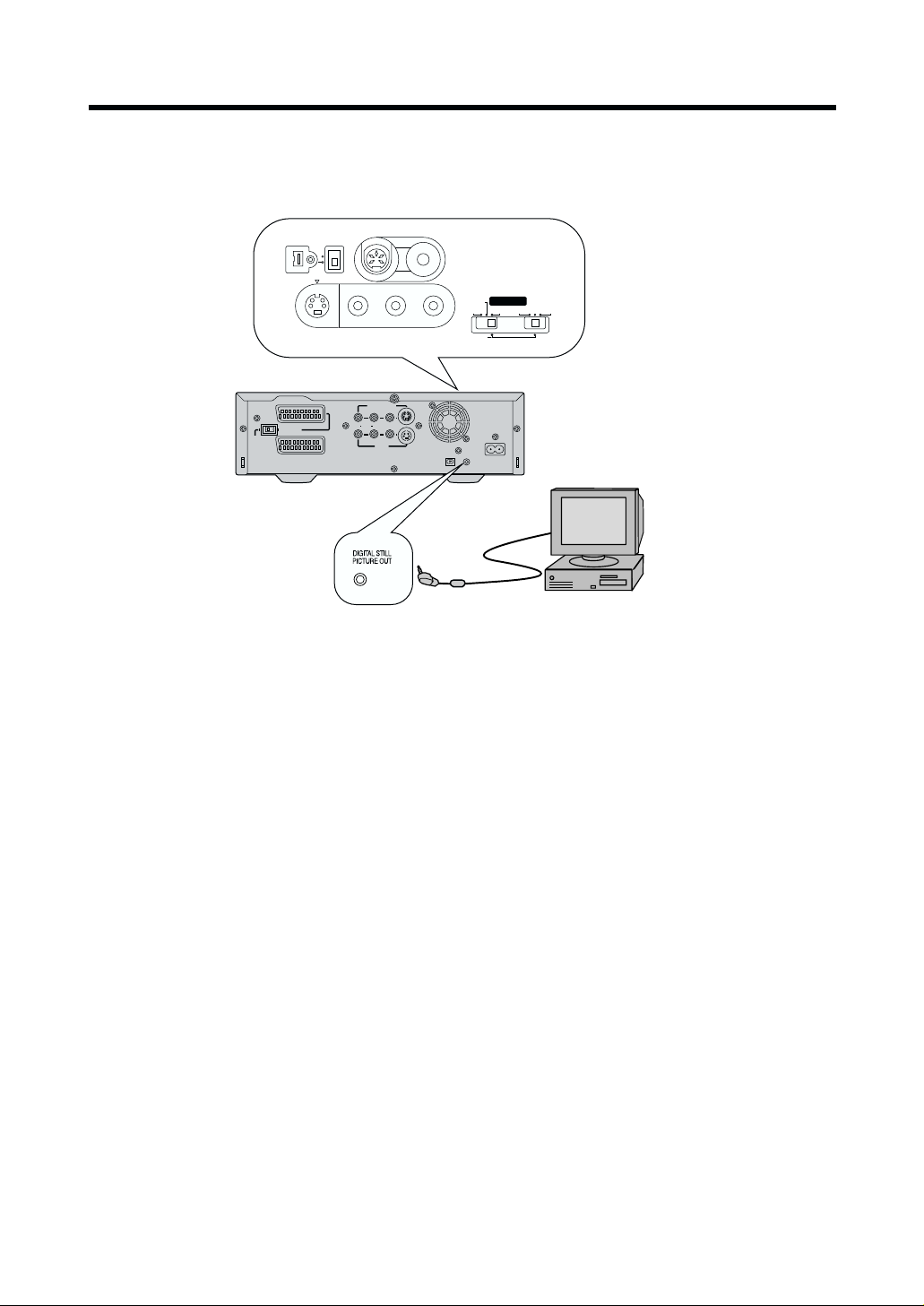
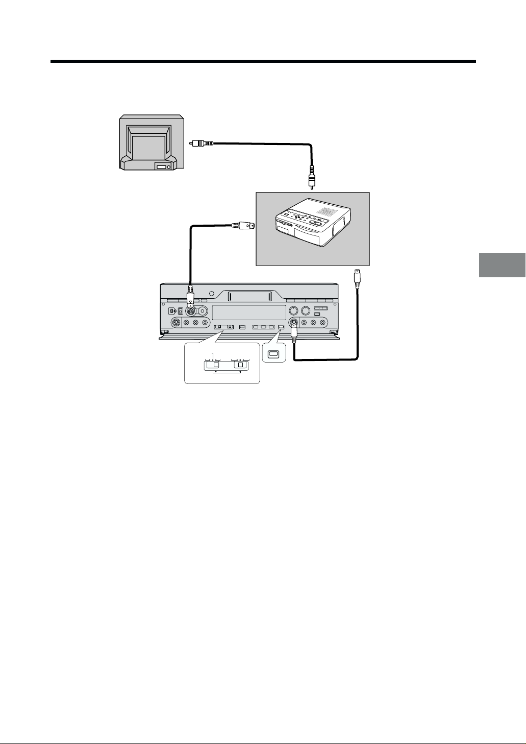
Using the VCR with a Computer
EDIT CONTROLOL
RECORDER
PRINTER/
.STILL PICTURE
YER
ASSIVE
The Personal Computer Connection Kit VW-DTA9/10E (Optional) for Digital Video Equipment performs it possible to
connect the VCR to a computer and transmit still video images to it.
front side
DV SELECT
1
2
EDIT 8mm
VIDEO
MONITOR OUT
R AUDIO L
L/MONO-AUDIO-R
VIDEO S-VIDEO
AV3 IN
EDIT CONTR
RECORDER
PLAYER
PASSIVE
DV
PRINTER/
D.STILL PICTURE
AC INT
SECTEUR
T
DIGITAL STILL
¥
DV 1
PICTURE OUT
Interface Adapter
(Not supplied)
8mm
EDIT
Computer (Not supplied)
NORMAL
AV4
IN
¥
S-VIDEO OUT
DV2
AV1
AV2(EXT
S-VIDEO
(TV)
)
Computer System Requirements
DV STUDIO can be installed in a PC/AT personal
computer which can run Microsoftg Windowsg 95/98.
Compatible machines: Personal computer with
80486DX4 or higher CPU
(Pentium™ or higher
recommended)
Graphic card: True Color (approx.16.7million
colours) recommended
(operation also possible even
with 256 colours)
Installed memory: 16 MB or more (32 MB or
more recommended)
Free hard disk space: At least 16 MB
Disk drive: CD-ROM drive
Serial port: RS-232C (D-Sub 9pin) or USB
Other requirements: Mouse
To connect the VCR to the computer, use the special
Interface Adaptor contained in the Personal Computer
Connection Kit.
≥ To use the DV STUDIO 2 software via USB, a
computer with Windowsg 98 preinstalled is necessary.
≥ Pictures that you intend to import into a computer
application should be recorded in the SP mode.
≥ When recording, take care that the Time Code is
uninterrupted from the beginning of the tape.
≥ For detailed of explanations on the operating
environment, connections and operations, refer to the
Personal Computer Connection Kit's operating
instructions.
≥ Windowsg 95/98 is a trademark of Microsoft
Corporation U.S.A.
≥ Pentium™ is a trademark of Intel Corporation.
≥ All other company and product names in the
operating instructions are trademarks of their
respective corporations.
Notes:
≥ If you use a DV cable to connect the VCR with a
computer and they do not function, contact the
software manufacturer.
≥ Connect the DV cable to the socket that matches the
number of the DV SELECT that was selected. There
is one DV Input/Output socket on the front of the
unit, and one on the back.
20
Page 21
Clock Setting/Shipping Condition
SET UP
Edit functions
VCR functions
Clock setting
Shipping conditon
DIGITAL VCR
To set the clock
The built-in clock must be set to the correct time.
The built-in digital clock employs the 24-hour system.
The clock backup system operates for at least 60
minutes in the event of power failure.
Preparations
≥ Confirm that the TV is on and the VCR viewing
channel is selected.
≥ Turn on the VCR.
Operations
1 Press SET UP, and then
press 34 (CURSOR) to
select Clock setting and
press OK.
2 Press 3421
(CURSOR) to set Time
and Date.
3 Press OK to confirm.
4 Press EXIT.
On Screen Display
SET UP
Edit functions
VCR functions
Clock setting
Shipping conditon
Clock setting
Time : 19:22:36
Date : 07.02.00
To Initialise VCR Functions and
Edit Functions
If you want to return the VCR to the factory-preset
condition, follow the procedure below.
Operations
1 Press SET UP, and then
press 34(CURSOR) to
select Shipping condition
and press OK.
2 Press 21(CURSOR) to
select YES.
3 Press OK to confirm.
4 Press EXIT.
Note:
≥ If you perform Shipping Condition, the clock setting is
not initialised.
Shipping condition
NO YES
Various Settings
21
Page 22

Settings for VCR Functions
The VCR indications shown on the TV screen are known
as the On Screen Display (OSD).
This VCR allows many settings to be made at the OSD.
See [R36] for setting for Edit functions.
Editing controller
DIGITAL VCR
Preparation
≥ Turn on the VCR and TV.
OSD
Operations
1 Press SET UP, and then
press 34 (CURSOR)
to select VCR functions
and press OK.
2 Press 341
(CURSOR) to select
OSD.
3 Press 34 (CURSOR) to select AUTO, ON or
OFF, and then press OK.
AUTO: The On Screen Display will appear on the
TV screen for a few seconds when you
operate the VCR.
ON: The On Screen Display will always appear
on the TV screen when you perform the
VCR.
OFF: The On Screen Display will not appear.
(except for Recorded Date and Time)
On Screen Display
SET UP
Edit functions
VCR functions
Clock setting
Shipping conditon
VCR functions
OSD : AUTO
VCR display : DIMMED
Colour mode : COLOUR
Comb filter : ON
TBC : ON
REC DNR : LEVEL1
PB DNR : LEVEL1
Remote : VCR1
1 Audio Data Indicator
2 Audio Output Mode Indicator
The Left (L) and Right (R) Indicators show which
sound mode is selected with AUDIO OUT.
Stereo: Both the L and R Indicators appear.
Left: The L Indicator appears.
Right: The R Indicator appears.
3 Tape speed Indicator
4 Audio Monitor Indicator
ST1: 12bit STEREO1 sound
ST2: 12bit STEREO2 sound
MIX: STEREO1 and STEREO2 mixed sound.
Picture
5 Tape running display
Stop ∫
Rewind 6
Fast Forward 5
Playback 1
Reverse Playback 2
Reverse Slow Playback G
Slow Playback F
Still Playback, Pause ;
Recording ¥
6 Present time/Time code/Remaining tape
time/Tape counter/Index/Photoshot Index
Search/One-Touch Recording (OTR)
Present time 17:24:31
Time code
TC 0h25m32s04f
Remaining tape time REMAIN: 1:04
Tape counter j1:35:47
Index/Photoshot index Search 5 02
One-Touch Recording (OTR) OTR 60
7 Index/Photoshot Index Search Indicator
4 Press EXIT to exit the On Screen Display.
To use the On Screen Display:
22
Notes:
≥ When the item OSD is set to OFF, the On Screen
Display will not appear.
1
3
2
bit
≥ On Screen Display is not displayed when the SET UP
4
or EDIT MENU screen is displayed.
≥ On Screen Display (4) is not displayed while playing
a tape that was recorded in 16bit audio mode.
≥ When a wide-display TV is used as a monitor, parts of
the On Screen Display may not be visible depending
on the type of signal (16:9, PAL Plus) received.
1
6
5
7
Page 23

VCR display
Operations
1 Press SET UP, and then press 34 (CURSOR) to
select VCR functions and press OK.
Comb filter
Operations
1 Press SET UP, and then press 34 (CURSOR) to
select VCR functions and press OK.
2 Press 341
(CURSOR) to select
VCR display.
VCR functions
OSD : AUTO
VCR display : DIMMED
Colour mode : COLOUR
Comb filter : ON
TBC : ON
REC DNR : LEVEL1
PB DNR : LEVEL1
Remote : VCR1
3 Press 34(CURSOR) to select ON, OFF or
DIMMED, and then press OK.
ON: When VCR is turned off, the characters
are lit in the VCR display.
OFF: When VCR is turned off, the characters
are not lit in the VCR display.
DIMMED: When VCR is turned off, the characters
are dimmed in the VCR display.
4 Press EXIT to exit the On Screen Display.
To Set the Colour mode
Operations
1 Press SET UP, and then press 34 (CURSOR) to
select VCR functions and press OK.
2 Press 341
(CURSOR) to select
Colour mode.
3 Press 34 (CURSOR) to select COLOUR or
B/W, and then press OK.
COLOUR: When performing playback in colour.
B/W: When performing playback in black and
white.
VCR functions
OSD : AUTO
VCR display : DIMMED
Colour mode : COLOUR
Comb filter : ON
TBC : ON
REC DNR : LEVEL1
PB DNR : LEVEL1
Remote : VCR1
2 Press 34 1
(CURSOR) to select
Comb filter.
VCR functions
OSD : AUTO
VCR display : DIMMED
Colour mode : COLOUR
Comb filter : ON
TBC : ON
REC DNR : LEVEL1
PB DNR : LEVEL1
Remote : VCR1
3 Press 34(CURSOR) to select ON or OFF, and
then press OK.
ON: Set to increase detail. Normally set to this
position.
OFF: Set to reduce picture noise.
4 Press EXIT to exit the On Screen Display.
Setting for TBC Function
(For Recording only)
Operations
1 Press SET UP, and then press 34 (CURSOR) to
select VCR functions and press OK.
2 Press 341
(CURSOR) to select
TBC.
3 Press 34 (CURSOR) to select ON or OFF, and
then press OK.
ON: When recording analogue VCR the shaking
and distortion of the pictures are reduced
during playback.
OFF: When the horizontal lines appear during
playback of the edited picture even if TBC
is set to ON, set to OFF.
VCR functions
OSD : AUTO
VCR display : DIMMED
Colour mode : COLOUR
Comb filter : ON
TBC : ON
REC DNR : LEVEL1
PB DNR : LEVEL1
Remote : VCR1
Various Settings
4 Press EXIT to exit the On Screen Display.
4 Press EXIT to exit the On Screen Display.
≥ Alternatively, you can press the TBC button of the
VCR and set for the TBC function. [R17]
23
Page 24

Editing controller
DIGITAL VCR
For Playback
Operations
1 Press SET UP and press 34 (CURSOR) to
select VCR functions and press OK.
Settings for 3D DNR
(REC DNR/PB DNR) Function
For Recording
Operations
1 Press SET UP and
press 34 (CURSOR)
to select VCR
functions and press
OK.
2 Press 341
(CURSOR) to select
REC DNR.
3 Press 34 (CURSOR)
to select LEVEL1 or
LEVEL2 and press OK.
LEVEL1: To ensure 3D DNR effect
LEVEL2: To ensure high 3D DNR effect
4 Press EXIT to exit the On Screen Display.
SET UP
Edit functions
VCR functions
Clock setting
Shipping conditon
VCR functions
OSD : AUTO
VCR display : DIMMED
Colour mode : COLOUR
Comb filter : ON
TBC : ON
REC DNR : LEVEL1
PB DNR : LEVEL1
Remote : VCR1
2 Press 341
(CURSOR) to select PB
DNR.
3 Press 34 (CURSOR)
to select LEVEL1 or
VCR functions
OSD : AUTO
VCR display : DIMMED
Colour mode : COLOUR
Comb filter : ON
TBC : ON
REC DNR : LEVEL1
PB DNR : LEVEL1
Remote : VCR1
LEVEL2 and press OK.
LEVEL1: To ensure 3D DNR effect
LEVEL2: To ensure high 3D DNR effect
4 Press EXIT to exit the On Screen Display.
≥ After setting the 3D DNR function, press the 3D DNR
button until the “PB DNR” indication appears on
display before or during playback to ensure high
picture quality.
To Set the Remote mode
Operations
1 Press SET UP, and then press 34 (CURSOR) to
select VCR functions and press OK.
2 Press 341
(CURSOR) to select
Remote.
VCR functions
OSD : AUTO
VCR display : DIMMED
Colour mode : COLOUR
Comb filter : ON
TBC : ON
REC DNR : LEVEL1
PB DNR : LEVEL1
Remote : VCR1
≥ After setting the 3D DNR function, press the 3D DNR
button until the “REC DNR” indication appears on
the display before recording to ensure high picture
quality.
24
3 Press 34 (CURSOR) to select VCR1, VCR2 or
VCR3 and press OK.
This allows the Editing controller to be set for
operating VCR1, VCR2 or VCR3.
≥ After changing the remote mode, slide the VCR
1/2/3 switch to change the remote mode of the
Editing controller. If this is not done, it will not be
possible to operate the VCR using the Editing
controller. [R11]
4 Press EXIT to exit the On Screen Display.
Page 25

Editing Functions
Using this VCR, 4 types of One-Touch-Edit, 3 types of
Manual Editing and 3 types of Programme Editing
can be selected.
In Programme Editing, after setting the edit start/end
point, editing can be performed automatically. Edit
programmes can be set up to 10 scenes for each editing
function (20 scenes for Assemble editing).
Programme editing with Time Code enables high edit
accuracy, typically within 5 frames at the edit start point
(1 frame=1/25th of a second).
The accuracy of the edit start/end point on the playback
VCR will vary depending on the VCR/Movie Camera
being used. Use the Edit Timing Adjustment function to
give the best possible accuracy.
Copying
Allows the re-recording (copying) of the picture and
sound from one tape onto another tape.
One-Touch-Edit
≥ Assemble Editing [R40]
≥ Inser t Editing (Video, Audio, AV) [R41]
≥ Audio Dubbing [R41]
≥ Audio Mixing [R42]
Manual Editing
≥ Copying [R43]
≥ Inser t Editing (Video, Audio, AV) [R44]
≥ Audio Dubbing [R45]
Programme Editing
≥ Assemble Editing [R46]
≥ Inser t Editing (Video, Audio, AV) [R48]
≥ Audio Dubbing [R50]
Video Insert
Allows the partial replacement of the picture on a
recorded tape. Sound is left in its original state.
Audio Insert
Allows the partial replacement of sound on a recorded
tape. Picture is left in its original state.
AV Insert
Allows the partial replacement of the picture and sound
on a recorded tape.
Performing the Copying operation on a tape that was
recorded in 12bit audio mode.
Preparations for Editing
Performing the AV Insert editing operation on a tape that
was recorded in 12bit audio mode.
25
Page 26

Editing Functions (continued)
Audio Dubbing
Allows the addition of the new sound on the STEREO2
track of a recorded tape. The original sound is left on the
STEREO1 track.
Performing the Audio Dubbing operation on a tape that
was recorded in 12bit audio mode.
Audio Mixing
Allows the mixing of the original sound on the
STEREO1 track with the new sound from the external
recording source and recording the mixed sound on the
STEREO2 track of a recorded tape. The original sound
is left on the STEREO1 track.
Assemble Editing
Allows the required scenes (picture and sound) to be
picked up from a recorded tape and recorded in any
desired order onto another tape.
26
Performing the Programme Assemble editing operation
on a tape that was recorded in 12bit audio mode.
Page 27

Creating the Tapes for Editing
In order to operate editing functions correctly, use these tapes for editing as follows:
≥ Tape on which the picture and sound have been recorded properly for about 20 seconds prior to the edit
start point: [Playback unit] [Recording unit]
This VCR first rewinds the tape to the section prior to the edit start point and then commences editing. For this
reason, accurate editing cannot be performed if the tape has been left blank or if the picture and sound have not
been recorded properly for 20 seconds prior to the edit start point.
≥ Tape on which the Time code has been recorded continuously: [Playback unit] [Recording unit]
If the recording is broken up or if the tape is blank in places, the Time code will lack continuity, and editing will be
aborted.
≥ Tape which was recorded in SP mode: [Recording unit]
(This applies to Insert, Audio Dubbing and Audio Mixing only.)
The above types of editing operations cannot be performed on a tape which was recorded in the LP mode.
≥ Tape which was recorded in the 12bit audio mode: [Recording unit]
(This applies to AV Insert, Audio Dubbing and Audio Mixing editing only.)
The above types of editing operations cannot be performed on a tape which was recorded in the 16bit audio mode.
When a tape which was recorded on another video recorder is used for Inser t, Audio Dubbing or Audio
Mixing editing operations, the sound may deteriorate and the picture may be disturbed.
If tapes answering to the above description are not available, proceed with dubbing by
following the steps below to create the tapes for editing.
1 Load the original cassette tape into the playback unit and the new cassette tape into the recording VCR (the NV-
DV2000).
2 Connect the playback unit and recording VCR (the NV-DV2000).
For the connection, use the DV cable when the contents of the original cassette are to be copied using their
original digital signals, and use the AV cables when the contents are to be copied using the signals from the video
and audio sockets.
(To dub a 16bit audio tape and make a 12bit audio tape, connect the units using the AV cables, and proceed with
the dubbing.)
3 Set the VCR’s tape speed to SP.
4 Record a blank picture for about 20 seconds.
Set the playback unit to the stop mode, set INPUT SELECT on the recording VCR (the NV-DV2000) to A2, A3 or
A4, and start recording.
5 Switch over the input of the recording VCR (the NV-DV2000).
If the DV cable was used for the connection in step 2, select “DV1” or “DV2”; if the AV cable was used, switch over
to A1, A2, A3 or A4.
6 Press 1 (PLAY) on the playback unit to start playing the original tape.
7 Press ¥ (REC) on the recording VCR (the NV-DV2000) to start dubbing.
Notes:
≥ Digital copying using a DV cable yields a picture quality which undergoes hardly any deterioration at all.
≥ If a digital video tape is dubbed without connecting the DV cable, the original sub code data (Photoshot index
signals, date information, etc.) will not be copied.
≥ The Time code is simultaneously recorded over the subcode of the tape when the tape is recorded. Also recorded
in the sub code are the photoshot index signals, information on the recording date, etc. For further details on the
Time code, see [R58].
Preparations for Editing
27
Page 28

V4
EDIT CONTROLOL
RECORDER
PRINTER/
.STILL PICTURE
PLA
ASSIVE
Connecting with a Panasonic Digital Video Camera
Example for connecting Panasonic NV-DS25 Digital Video Camera as the playback unit, when controlling the
playback unit through the NV-DV2000.
AV1 (Rear)
Recording Unit
Playback Unit
DV SELECT
1
2
EDIT 8mm
¥
DV2
Notes:
≥ Before connecting any cables, first make sure that the
power for both units is off.
≥ Inser t a recorded cassette into the playback unit, and
a cassette with the closed record prevention tab into
the VCR.
≥ If the playback unit is connected to the recording unit
via an S-VIDEO cable, the video signal on the
S-VIDEO cable takes priority. If the playback unit
does not have an S-VIDEO socket, do not connect
the S-VIDEO cable to the NV-DV2000.
≥ Use of an AC adaptor as the power source for the
Digital Video Camera is recommended. Doing so
avoids a situation where the camera shuts down due
to low battery power.
EDIT CONTR
AV4
IN
VIDEO
S-VIDEO
L/MONO-AUDIO-R
RECORDER
PLA
YER
PRINTER/
D.STILL PICTURE
PASSIVE
8mm
EDIT
DV
≥ It is recommended that the DV cable be disconnected
for editing with INPUT SELECT set to A1-A4. If
INPUT SELECT is set to A1-A4 with the connections
shown in the figure left unchanged, the TV picture
may be disturbed or noise may occur. (This has no
effect on the actual editing operations.)
≥ When the units are connected using the DV cable and
editing is performed, some editing functions will differ
compared with when the units are connected using
the AV cables. Refer to Glossary of Terms on [R58].
≥ Read the operating instr uctions of the Digital Video
movie Camera.
≥ Do not change the Edit Terminal or Edit Mode
settings while performing setting or editing operations
at the SET UP or EDIT MENU screens. Be sure to
quit these screens before changing these settings.
28
Page 29

Playback Unit
V4
EDIT CONTROLOL
RECORDER
PRINTER/
.STILL PICTURE
ASSIVE
(Digital Video Camera)
1 Turn on the DVC.
2 Make the Time code appear on the LCD monitor or
the viewfinder.
3 Prepare the tape for playback.
Recording Unit
(the NV-DV2000)
1 Turn on the VCR.
2 Set Edit Mode to RECORDER.
3 Set Edit Terminal to EDIT.
4 Press INPUT SELECT so that DV1 or DV2 after
sliding DV SELECT switch 1 or 2, is selected.
≥ When performing Audio Dubbing or AV Insert,
select A2, A3 or A4.
Notes:
≥ When using a Panasonic Digital Video Camera as the
playback unit, the following editing functions can be
used by connecting the camera to the NV-DV2000
with just a DV cable:
Copying (See page 43 after seeing page
25.)
Video Insert (See pages 44 and 48 after seeing
page 25.)
Audio Insert (See pages 44 and 48 after seeing
page 25.)
Assemble (See pages 40 and 46 after seeing
page 26.)
except Audio Dubbing, Audio Mixing and AV
Insert
In this case, simply set INPUT SELECT to DV1 or
DV2, and set Edit Terminal to DV.
(This function may not operate properly with some
models.)
≥ Use Time codes for Programme Editing when the
playback unit is connected to the NV-DV2000 via only
a DV cable.
≥ Select the DV SELECT switch setting in accordance
with the connected socket.
AV4
4
DV SELECT
1
2
EDIT 8mm
VIDEO
L/MONO-AUDIO-R
NV-DV2000
EDIT CONTR
RECORDER
PLAYER
PASSIVE
PRINTER/
D.STILL PICTURE
8mm
EDIT
DV
¥
DV2
IN
S-VIDEO
23
Preparations for Editing
29
Page 30

V SELECT
EDIT CONTROLOL
RECORDER
PRINTER/
.STILL PICTURE
PLA
YER
ASSIVE
EDIT
8mm
EDIT CONTROLOL
RECORDER
PRINTER/
.STILL PICTURE
PLA
YER
ASSIVE
8mm
Connecting Two Digital Video Cassette Recorders (Both Panasonic models)
Example for connecting two NV-DV2000, when controlling the playback VCR through the recording VCR.
Refer to the diagram below and connect the cables required for the desired editing function.
(Front)
¥
DV2V2DV SELECT
AV4
IN
S-VIDEO
EDIT 8mm
1
2
EDIT CONTR
VIDEO
L/MONO-AUDIO-R
RECORDER
PLA
YER
PRINTER/
D.STILL PICTURE
PASSIVE
8mm
EDIT
DV
Playback VCR
AV1
MONITOR OUT
Notes:
≥ Before connecting any cables, first make sure that the
power for both VCRs is off.
≥ Inser t a recorded cassette into the playback VCR, and
a cassette with the closed record prevention tab into
the VCR.
≥ When the units are connected using the DV cable and
editing is performed, some editing functions will differ
compared with when the units are connected using
the AV cable. Refer to Glossary of Terms on [R58].
≥ Use Time codes for programme editing when the
playback VCR is connected to the NV-DV2000 via
only a DV cable.
≥ It is recommended that the DV cable be disconnected
for editing with INPUT SELECT set to A1-A4. If
INPUT SELECT is set to A1-A4 with the connections
shown in the figure left unchanged, the TV picture
may be disturbed or noise may occur. (This has no
effect on the actual editing operations.)
≥ If one of either the 21-pin scar t cable or the AV cables
is connected, it is not necessary to connect the other.
If both cables are connected, electronic noise may be
generated when the playback VCR and the recording
VCR are in stop mode. Although this noise will not
have any effect on the actual editing operations, if it
does become annoying, set INPUT SELECT on the
playback VCR to a position for which no cable is
connected.
AV2 (Rear)
AV1(Rear)
Recording VCR
¥
DV2V2DV SELECT
AV4
IN
S-VIDEO
EDIT 8mm
1
2
EDIT CONTR
VIDEO
L/MONO-AUDIO-R
RECORDER
PLA
YER
PRINTER/
D.STILL PICTURE
PASSIVE
8mm
EDIT
DV
≥ When the connections and setting are made as
shown above, then:
≥ The 1 (PLAY), 5 (FAST FORWARD),
¥¥
¥ (REC/
¥¥
OTR), and the other such buttons on the playback
VCR or the Editing controller cannot be used to
control the playback VCR directly.
≥ Do not change Edit Terminal or Edit Mode settings
while performing setting or editing operations at SET
UP or EDIT MENU screens. Be sure to quit these
screens before changing these settings.
30
Page 31

Playback VCR
1 Turn on the VCR.
2 Set Edit Mode to PASSIVE.
3 Set Edit Terminal to EDIT.
(Set DV SELECT to 1 or 2.)
Recording VCR
1 Turn on the VCR.
2 Set Edit Mode to RECORDER.
3 Set Edit Terminal to EDIT.
4 Press INPUT SELECT so that DV1 or DV2 after
sliding DV SELECT to 1 or 2, is selected.
≥ When performing Audio Dubbing or AV Insert,
select A2, A3 or A4.
Note:
The following editing functions can be used by
connecting the playback VCR with just a DV cable:
Copying (See page 43 after seeing page
25.)
Video Insert (See pages 44 and 48 after seeing
page 25.)
Audio Insert (See pages 44 and 48 after seeing
page 25.)
Assemble (See pages 40 and 46 after seeing
page 26.)
except Audio Dubbing, Audio Mixing and AV
Insert
In this case, simply set INPUT SELECT to DV 1 or DV 2,
and set Edit Terminal to DV.
Controlling the Recording VCR through
the Playback VCR
Follow the procedure described below:
≥ Connect the edit cable to the EDIT socket on both
the playback VCR and the recording VCR.
≥ Use 21-pin Scar t cable or AV cables to connect
the input sockets on the recording VCR with the
output sockets on the playback VCR.
≥ Connect two TVs, one to each of the VCRs, so
that the screens from both VCRs can both be
seen.
≥ Set Edit Terminal on both the playback VCR and
the recording VCR to EDIT.
≥ Press INPUT SELECT on the playback VCR and
select a position to which a cable is not
connected.
≥ Set Edit Mode on both VCRs as follows:
Playback VCR : PLAYER
Recording VCR : PASSIVE
Notes:
≥ When this connection is made, the recording VCR
cannot be controlled using the DV cable.
≥ Although noise may appear on the screen,
depending on the connections, the noise has no
effect on the actual editing operations.
≥ When connecting only with DV cable, Audio
Insert and AV Insert are not possible.
≥ When perfor ming editing with this connection, the
editing accuracy may be worse than when
controlled from the recording VCR.
2000
2000
Preparations for Editing
31
Page 32

Connecting an S-VHS (VHS) Video Equipment
V SELECT
EDIT
8mm
PRINTER/
.STILL PICTURE
PLA
YER
ASSIVE
EDIT
8mm
with an Edit Socket
Example for connecting an S-VHS (VHS) video equipment with an Edit socket as the playback unit, when controlling
the playback unit through the recording VCR (this unit).
Refer to the diagram below and connect the cables
required for the desired editing function.
Playback Unit
Notes:
≥ Before connecting any cables, first make sure that the
both units turn off.
≥ Inser t a recorded cassette into the playback unit, and
a cassette with the closed record prevention tab into
the VCR.
≥ If the playback unit is connected to the recording unit
via an S-VIDEO cable, the video signal on the
S-VIDEO cable takes priority. If the playback unit
does not have an S-VIDEO socket, do not connect
the S-VIDEO cable to the NV-DV2000.
≥ If one of either the 21-pin Scar t cable or the AV
cables is connected, it is not necessary to connect
the other.
If both cables are connected, electronic noise may be
generated when the playback VCR and the recording
VCR are in stop mode. Although this noise will not
have any effect on the actual editing operations, if it
does become annoying, set INPUT SELECT on the
playback VCR to a position for which no cable is
connected.
32
AV2 (Rear)
AV1 (Rear)
Recording Unit
EDIT
VIDEO
8mm
L/MONO-AUDIO-R
RECORDER
PLA
YER
PRINTER/
D.STILL PICTURE
EDIT CONTROL
PASSIVE
8mm
EDIT
DV
¥
DV2V2DV SELECT
AV4
IN
S-VIDEO
1
2
≥ Read the operating instr uctions of the playback unit.
≥ Do not change the Edit Terminal or Edit Mode
settings while performing setting or editing operations
at SET UP or EDIT MENU screens. Be sure to quit
these screens before changing these settings.
≥ When using this VCR as the recording VCR and
performing editing by connecting the units via the AV
cables or a 21-pin Scart cable, the On Screen Display
(date/time, Time Code) may scroll vertically when still
playback or slow playback are performed by the
playback VCR.
Page 33

Playback Unit
[S-VHS (VHS) Video Equipment with an
Edit socket]
1 Turn on the Video Equipment.
2 Set the unit so that it is ready to be controlled.
≥ Read the operating instructions of the playback
unit and make the necessary settings.
Recording VCR
(the NV-DV2000)
1 Turn on the VCR.
2 Set Edit Mode to RECORDER.
3 Set Edit Terminal to EDIT.
4 Press INPUT SELECT so that A2, A3 or A4 is
selected.
Hint:
When the “TBC” and “REC 3D DNR” functions activate,
you can record with the clear pictures. [R17,23,24]
Connecting the NV-DV2000 as the
Playback VCR to an S-VHS (VHS) VCR
Follow the procedure described below.
≥ Use AV cables to connect the output sockets on
the NV-DV2000 with the input sockets on the
S-VHS (VHS) VCR.
≥ Press INPUT SELECT on the NV-DV2000 so that
A2, A3 or A4 is selected.
≥ Connect two TVs, one to the NV-DV2000 and one
to the S-VHS (VHS) VCR, so that the screens
from both VCRs can both be seen.
≥ Set Edit Mode on the NV-DV2000 to PLAYER.
≥ Make the necessary editing control settings for
the S-VHS (VHS) VCR. Read the operating
instructions of S-VHS (VHS) VCR.
Preparations for Editing
2000
Note:
Audio Insert and AV Insert are not possible in this
configuration.
33
Page 34

Connecting a Video Equipment with a LANC
EDIT CONTROLOL
Socket
Example for connecting another manufacturer’s video equipment with a LANC terminal (L control) as the playback
unit, when controlling the playback unit through the VCR.
AV1 (Rear)
8mm
Notes:
≥ Do not change the Edit Terminal or Edit Mode
settings while performing setting or editing operations
on the SET UP or EDIT MENU screens. Be sure to
exit these screens before changing these settings.
≥ When using this VCR as the recording VCR and
performing editing by connecting the units via the AV
cables or a 21-pin Scart cable, the On Screen Display
(date/time, Time Code) may scroll vertically when still
playback or slow playback are performed by the
playback VCR.
¡ Before connecting any cables, first make sure that the
both units turn off.
¡ Insert a recorded cassette into the playback unit, and
a cassette with the closed record prevention tab into
the VCR.
¡ The NV-DV2000 cannot be controlled through video
equipment with a LANC socket.
S-VIDEO
DV SELECT
1
2
EDIT 8mm
VIDEO
L/MONO-AUDIO-R
RECORDER
PLAYER
PRINTER/
D.STILL PICTURE
EDIT CONTR
PASSIVE
DV
8mm
EDIT
¥
DV2
AV4
IN
Playback Unit
with a LANC socket
(8mm Video Camera etc.)
¡ Some types of LANC sockets have a different shape
to the LANC socket on the NV-DV2000.
¡ If an attempt is made to perform an operation through
the NV-DV2000 that the playback unit does not
support, the unit may operate incorrectly.
¡ If the playback unit is connected to the recording unit
via an S-VIDEO cable, the video signal on the
S-VIDEO cable takes priority. If the playback unit
does not have an S-VIDEO socket, do not connect
the S-VIDEO cable to the NV-DV2000.
¡ When the units are connected using the DV cable and
editing is performed, some editing functions will differ
compared with when the units are connected using
the AV cables. Refer to Glossary of Terms on [R58].
¡ Read the operating instructions of the playback unit.
34
Page 35

Playback Unit
(a Video Equipment with a LANC socket)
Recording VCR
(the NV-DV2000)
1 Turn on the Video Equipment.
2 Set the unit so that it is ready to be controlled.
≥ Read the operating instructions of the playback
unit and make the necessary settings.
1 Turn on the VCR.
2 Set Edit Terminal to 8mm.
3 Press INPUT SELECT so that A3 or A4 is
selected.
≥ If the playback unit is connected to the external
input on the rear of the NV-DV2000, select A2.
≥ Press INPUT SELECT so that DV1 or DV2 after
sliding DV SELECT to 1 or 2, is selected.
≥ When performing Audio Dubbing, Audio Mixing
or AV Insert, select A2, A3 or A4.
Preparations for Editing
35
Page 36

Settings for Editing
This VCR also allows some settings for editing to be made at the On Screen Display (OSD).
Audio mode
Operations
DIGITAL VCR
1 Press SET UP.
2 Press 34(CURSOR) to
select Edit functions
and press OK.
SET UP
Edit functions
VCR functions
Clock setting
Shipping conditon
Preparations
¡ Confirm that the TV is on and the VCR viewing
channel is selected.
¡ Complete necessary connections and settings.
[R28–35]
Search with Sound
Operations
1 Press SET UP.
2 Press 34(CURSOR) to
On Screen Display
SET UP
Edit functions
VCR functions
Clock setting
Shipping conditon
select Edit functions
and press OK.
Edit functions
3 Press 34(CURSOR) to
select Search with
Sound and press OK.
4 Press 34(CURSOR) to
select OFF, EDIT ONLY
or ALWAYS ON, and
Search with Sound
Audio mode
One-Touch-Edit
Still Album
Search with Sound
OFF
EDIT ONLY
ALWAYS ON
then press OK.
3 Press 34(CURSOR) to
select Audio mode and
press OK.
Edit functions
Search with Sound
Audio mode
One-Touch-Edit
Still Album
4 Press 21 (CURSOR)
to select 12bit or 16bit,
and then press OK.
Audio mode
12bit
12bit: Divides the audio area into two
stereo audio tracks and four
channels: STEREO1 (L-R) and
STEREO2 (L-R).
≥ If a recording is made in 12bit
audio mode, the sound is
recorded on STEREO1 only, and
is not recorded on STEREO2.
STEREO2 is used to record new
audio that is added through
Audio Dubbing or Audio Mixing.
16bit: The whole audio area is used so
that the sound will be recorded with
a superior quality.
5 Press EXIT to exit the On Screen Display.
16bit
OFF: The sound cannot be heard during
special playback.
EDIT ONLY: The sound can be heard during
special playback only when an
editing operation is in progress.
ALWAYS ON: The sound can be always heard
during special playback.
5 Press EXIT to exit the On Screen Display.
36
Page 37

Setting for One-Touch-Edit
Operations
1 Press SET UP.
2 Press 34 (CURSOR)
to select Edit
functions and press
OK.
SET UP
Edit functions
VCR functions
Clock setting
Shipping conditon
3 Press 34 (CURSOR)
to select One-Touch-
Edit and press OK.
Edit functions
Search with Sound
Audio mode
One-Touch-Edit
Still Album
One-Touch-Edit
4 Press 21 (CURSOR)
to select OFF or ON,
OFF
and then press OK.
OFF: Select this whenever you are
performing any editing function
other than One-Touch-Edit.
ON: Select this in order to perform One-
Touch-Edit.
≥ One-Touch-Edit is possible only when EDIT
Terminal is set to either DV, EDIT, or 8mm, and
Edit Mode is set to RECORDER.
5 Press EXIT to exit the On Screen Display.
[R40–42]
Setting for Album Function
Operations
1 Press SET UP.
2 Press 34 (CURSOR)
to select Edit functions
and press OK.
SET UP
Edit functions
VCR functions
Clock setting
Shipping conditon
ON
3 Press 34 (CURSOR)
to select Still Album
and press OK.
4 Press 21 (CURSOR)
to select recording time,
and OK.
5 Press EXIT to exit the
On Screen Display.
[R38]
Edit Functions
Search with Sound
Audio mode
One-Touch-Edit
Still Album
Still Album
Recording time
3
10 15
5
3
5 seconds
20
Preparations for Editing
37
Page 38

Album Function
The album function lets you collect desired scenes (both moving and still pictures) and create the equivalent of a
photo album but on a video cassette. The pictures can be copied onto the cassette from a video movie camera, a
digital still camera or another VCR for any period of time that can preset.
XING EDIT
REW STOP
AUDIO REC LEVEL
010
SP/LP TBC 3D NR PRINT
S-VIDEO
STEREO1
AUDIO MIX
STEREO1 STEREO2
VIDEO
PLAY
STILL
ALBUM
INPUT SELECT
100
L– AUDIO – R
FF PAUSE
¥
REC/OTR
AV4
OUT
Preparations
¡ Confirm that the TV is on and the VCR viewing
channel is selected.
¡ Complete necessary connections and settings.
[R28–35]
Operations
1 Press STILL ALBUM to
REC
put the VCR in the
recording pause mode.
2 When the desired point is reached on the playback
unit, press STILL ALBUM of this VCR again to
start recording.
The VCR records the picture (and sound) for
setting time and then automatically switches over to
the recording pause mode.
≥ See [R37] to change the Recording time.
3 Repeat steps 1 and 2 to
REC
record other scenes in
succession.
REW STOP
AUDIO REC LEVEL
010
STEREO1
AUDIO MIX
STEREO1 STEREO2
PLAY
STILL
ALBUM
INPUT SELECT
100
FF PAUSE
¥
REC/OTR
AV4
OUT
Notes:
≥ If you plan to connect a digital still camera, use a
camera equipped with a video output socket. Use the
cable supplied with the still camera to connect it. For
details, read the operating instructions of the
equipment to be connected.
≥ If you leave the VCR in the recording pause mode for
more than 5 minutes in step 1 or 3, the VCR
automatically switches over to the stop mode to
protect the video heads. In this case, press STILL
ALBUM again to put the VCR back in the recording
pause mode.
≥ If you want to add background music or narration to
the scenes recorded with the album function, perform
Audio Dubbing as explained.
≥ Depending on the output system of the digital still
camera, the pictures may not be recorded correctly.
4 When you have recorded all the desired scenes,
press ∫ (STOP) to finish recording.
38
Page 39

Editing when Not Using an Edit Cable
To connect a VCR or Video Movie Camer a without an Edit socket and use the NV-DV2000 as the Recording VCR.
DIGITAL VCR
OK
4
Preparations
≥ Complete necessar y connections and settings.
[R28–35]
≥ Connect the AV1 socket on the NV-DV2000 to the TV.
≥ Connect the AV2 socket or the AUDIO/VIDEO/S-
VIDEO IN (AV3/AV4) sockets on the NV-DV2000 to
the playback unit.
Set INPUT SELECT on this VCR as follows:
A2: Through the AV2 socket
A3: Through the AV3 sockets
A4: Through the AV4 sockets
≥ If the playback unit has a DV terminal, connect to the
DV1 or DV2 on the NV-DV2000 with a DV cable.
Operations
1 Using the controls on the playback unit, search for
the edit start point, and then pause the playback.
2 Press JOG/SHUTTLE on the recording VCR, and
check that the button is lit.
3 Search for the edit start point.
4 Press the button for the editing mode on the
NV-DV2000.
To copy the contents of the tape in the playback
unit as is: Press ¥ (REC).
To insert picture: Press VIDEO INSERT.
To insert sound: Press AUDIO INSERT.
To insert picture and sound: Press VIDEO INSERT
and then press AUDIO INSERT(or vice versa).
To add new sound: Press AUDIO DUB.
For Audio Mixing: Press AUDIO DUB and then
press MIXING EDIT on the front panel.
≥ The Audio Mixing procedure differs in part from
other editing operations. [R42]
6
4
5 Press ;/D (PAUSE/SLOW) on the NV-DV2000 and
6 Press ∫ (STOP) on the NV-DV2000, and then
Notes:
¡ Although Copying can be performed in LP mode,
Insert and Audio Dubbing cannot be performed with a
tape recorded in LP mode. It is necessary to first
copy the tape in SP mode.
¡ Video Insert and Audio Insert are not possible in
the following cases:
When the tape in the recording VCR (the NV-DV2000)
is:
Recorded in LP mode;
Blank, or contains a blank portion in the middle.
¡ AV Insert, Audio Dubbing and Audio Mixing are
not possible in the following cases:
When the tape in the recording VCR (the NV-DV2000)
is:
Recorded in 16bit audio mode;
Recorded in LP mode;
Blank, or contains a blank portion in the middle.
When INPUT SELECT is set to DV1 or DV2.
¡ If the time display on the NV-DV2000 is set to tape
counter mode during editing, the NV-DV2000 stops
the editing operation automatically when the counter
reaches “0:00.00”.
(This function does not work when using the Copying
or Audio Dubbing functions.)
2
3
5
start playback on the playback unit simultaneously.
≥ Editing begins.
press STOP on playback unit to stop editing.
For Quick Editing
39
Page 40

One-Touch Assemble
If the One-Touch Edit function is used, Assemble editing can be performed by controlling the playback unit through
the NV-DV2000.
1,5
DIGITAL VCR
3
Preparations
≥ Confir m that the TV is on and the VCR viewing
channel is selected.
≥ Complete necessar y connections and settings.
[R28–35]
≥ Set One-Touch-Edit to ON on Edit functions menu.
[R37]
Operations
1 Press JOG/SHUTTLE on the Editing controller, and
check that the button is lit.
2 Search for the edit start point on the recording
VCR.
3 Press ¥ (REC).
≥ The picture from the playback unit appears on the
screen.
4 Search for the edit start point on the playback unit.
6
QP
2,4
Notes:
¡ Although Assemble editing can be performed in LP
mode, Insert, Audio Dubbing, and Audio Mixing
cannot be performed with a tape recorded in LP
mode. It is necessary to first copy the tape in SP
mode.
¡ In order to ensure that the editing operation is
performed properly, the editing points should be set at
least 20 seconds after the beginning of the tape.
¡ When using the Editing controller for remote control:
In order to conserve battery power, JOG/SHUTTLE
turns off after 30 seconds.
If JOG/SHUTTLE turns off after the edit start point
has been set on the recording unit (step 2), it is
necessary to press JOG/SHUTTLE again (so that it is
lit) before searching for the edit start point on the
playback unit.
If JOG/SHUTTLE turns off after the edit start point
has been determined on the playback unit (step 4), it
is necessary to press JOG/SHUTTLE again in order
to start editing.
5 Press JOG/SHUTTLE on Editing controller.
≥ Editing begins.
≥ To continue editing, press JOG/SHUTTLE on the
Editing controller, and repeat steps 4–5.
6 Press ∫ (STOP) on the Editing controller to stop
editing.
40
Page 41

One-Touch Insert/Audio Dubbing
MIXING EDIT
If the One-Touch Edit functions is used, Inser t (Video Insert, Audio Insert, and AV Insert) and Audio Dubbing can be
performed by controlling the playback unit through the NV-DV2000.
3
1,5
DIGITAL VCR
6
¥
DV IN/OUT
AV4
2,4
DV SELECT
1
2
<
EJECT
Preparations
¡ Confirm that the TV is on and the VCR viewing
channel is selected.
¡ Complete necessary connections and settings.
[R28–35]
¡ Set One-Touch-Edit to ON on Edit functions menu.
[R37]
Operations
1 Press JOG/SHUTTLE on the Editing controller, and
check that the button is lit.
2 Search for the edit start point on the recording
VCR.
3 Press the button for the editing mode on the Editing
controller.
To insert picture: Press VIDEO
V INSERT
TBC
ST1
ST1
INSERT.
To insert sound: Press AUDIO
INSERT.
A INSERT
ST1
ST1
To inser t picture and sound: Press
VIDEO INSERT and then press
AUDIO INSERT (or vice versa).
To add new sound: Press AUDIO
DUB.
≥ The picture from the playback
AV INSERT
A DUB
ST1
ST1
ST 2
ST12
unit appears on the screen.
4 Search for the edit start point on the playback unit.
5 Press JOG/SHUTTLE on the Editing controller.
≥ Editing begins.
≥ To continue editing, press JOG/SHUTTLE on the
Editing controller, and repeat steps 4– 5.
6 Press ∫ (STOP) on the Editing controller to stop
editing.
STEREO
SERECT
EDIT 8mm CONTROL
AUDIO
OUT
RECORDER
PLAYER
PRINTER/
D.STILL PICTURE
EDIT CONTROL
PASSIVE
8mm
EDIT
CONTROL
DV
MIXING EDIT
SP/LP TBC 3D NR PRINT
REW STOP
AUDIO REC LEVEL
010
S-VIDEO
STEREO1
AUDIO MIX
STEREO1 STEREO2
VIDEO
PLAY
100
L– AUDIO – R
STILL
ALBUM
INPUT SELECT
FF PAUSE
¥
REC/OTR
AV4
OUT
To Listen to the Edited Audio After Audio
Dubbing
Press STEREO SELECT during playback and select
STEREO2.
dB -¶ 30 20 10 5 0 OVER
L
ST 2
ST1 2
Notes:
¡ Video Insert and Audio Insert are not possible in
the following cases:
When the tape in the recording VCR (the NV-DV2000)
is:
Recorded in LP mode;
Blank, or contains a blank portion in the middle.
¡ AV Insert and Audio Dubbing are not possible in
the following cases:
When the tape in the recording VCR (the NV-DV2000)
is:
Recorded in 16bit audio mode;
Recorded in LP mode;
Blank, or contains a blank portion in the middle.
When INPUT SELECT is set to DV1 or DV2.
¡ If the time display on the NV-DV2000 is set to tape
counter mode during editing, the NV-DV2000 stops
the editing operation automatically when the counter
reaches “0:00.00”.
¡ In order to ensure that the editing operation is
performed properly, the editing points should be set at
least 20 seconds after the beginning of the tape.
¡ When using the Editing controller for remote control:
In order to conserve battery power, JOG/SHUTTLE
turns off after 30 seconds.
If JOG/SHUTTLE turns off after the edit start point
has been set on the recording unit (step 2), it is
necessary to press JOG/SHUTTLE again (so that it is
lit) before searching for the edit start point on the
playback unit.
If JOG/SHUTTLE turns off after the edit start point
has been determined on the playback unit (step 4), it
is necessary to press JOG/SHUTTLE again in order
to start editing.
l l l l l l l l
R
l l l l l l l l l
For Quick Editing
41
Page 42

MIXING EDIT
One-Touch Audio Mixing
This function is used to mix the audio on STEREO1, which has already been recorded, with audio from a external
recording source (A2, A3 or A4), and record the result on STEREO2.
This function is useful for adding new audio, such as music or a narration, to the original audio which has already
been recorded.
3
1,5
DIGITAL VCR
7
2,5
AV4
¥
DV IN/OUT
<
DV SELECT
1
2
EJECT
Preparations
≥ Confir m that the TV is on and the VCR viewing
channel is selected.
≥ Complete necessar y connections and settings.
[R28–35]
≥ Set One-Touch-Edit to ON on Edit functions menu.
[R37]
Operations
1 Press JOG/SHUTTLE on the Editing controller, and
check that the button is lit.
2 Search for the edit start point on the
recording VCR.
3 Press AUDIO DUB on the Editing
controller.
≥ The picture from the playback unit
A DUB
ST 2
ST12
appears on the screen.
4 Press MIXING EDIT.
5 Search for the edit start point on the playback unit.
6 Press JOG/SHUTTLE on the Editing controller.
≥ Editing begins.
≥ If you wish to adjust the volume of the original
audio (STEREO1) and external recording source
(A2, A3 or A4) during Audio Mixing,
AUDIO MIX: To adjust the volume of the
original audio (STEREO1).
AUDIO REC LEVEL: To adjust the volume of the
audio from external recording
source (A2, A3 or A4).
dB -¶ 30 20 10 5 0 OVER
L
ST1 2
ST1 2
l l l l l l l l
R
l l l l l l l l l
AUDIO
STEREO
SERECT
EDIT 8mm CONTROL
OUT
RECORDER
PLAYER
PRINTER/
D.STILL PICTURE
EDIT CONTROL
PASSIVE
8mm
EDIT
CONTROL
MIXING EDIT
DV
SP/LP TBC 3D DNR PRINT
4
REW STOP
PLAY
STEREO1
AUDIO MIX
STEREO1 STEREO2
VIDEO
ALBUM
INPUT SELECT
100
L– AUDIO – R
STILL
AUDIO REC LEVEL
010
S-VIDEO
6
To Monitor the Mixed Audio after Audio Mixing
Press STEREO SELECT during playback and select
STEREO2.
dB -¶ 30 20 10 5 0 OVER
L
ST 2
ST1 2
Notes:
¡ Audio Mixing is not possible in the following
cases:
When the tape in the recording VCR (the NV-DV2000)
is:
Recorded in 16bit audio mode;
Recorded in LP mode;
Blank, or contains a blank portion in the middle.
When INPUT SELECT is set to DV1 or DV 2.
¡ In order to ensure that the editing operation is
performed properly, the editing points should be set at
least 20 seconds after the beginning of the tape.
¡ When using the Editing controller for remote control:
In order to conserve battery power, JOG/SHUTTLE
turns off after 30 seconds.
If JOG/SHUTTLE turns off after the edit start point
has been set on the recording unit (step 2), it is
necessary to press JOG/SHUTTLE again (so that it is
lit) before searching for the edit start point on the
playback unit.
If JOG/SHUTTLE turns off after the edit start point
has been determined on the playback unit (step 5), it
is necessary to press JOG/SHUTTLE again in order
to start editing.
l l l l l l l l
R
l l l l l l l l l
FF PAUSE
¥
REC/OTR
AV4
OUT
7 Press ∫
42
≥ To continue editing, press JOG/SHUTTLE on the
Editing controller, and repeat steps 5–6.
(STOP) on the Editing controller to stop
editing.
Page 43

Manual Copying
This function can be used to copy tapes between digital
video equipments with practically no deterioration in
quality.
This function can also copy a tape that was recorded in
S-VHS (VHS) format onto a digital video tape.
3,5
4,6
DIGITAL VCR
2,7
3
1,9
5
Preparations
≥ Confir m that the TV is on and the VCR viewing
channel is selected.
≥ Complete necessar y connections and settings.
[R28–35]
Operations
01 Press EDIT MENU.
02 Press 34 (CURSOR)
to select Copying, and
then press OK.
On Screen Display
EDIT MENU
Copying
Video Insert
Audio Insert
AV Insert
Audio Dubbing
Programme Editing
09 Press EDIT MENU to stop editing.
≥ Operation now returns to the screen which
appears in step 3. This makes it possible to
continue with editing or change the point at which
editing is to start.
10 Press EXIT.
≥ The On Screen Display disappears.
Notes:
≥ If a digital video tape is copied without connecting a
DV cable, the original sub code data (photoshot index
signals, recording date, etc.) is not copied.
≥ Although Copying can be performed in LP mode,
Insert and Audio Dubbing cannot be performed with a
tape recorded in LP mode. It is necessary to first
copy the tape in SP mode.
≥ In order to ensure that the editing operation is
performed properly, the editing points should be set at
least 20 seconds after the beginning of the tape.
≥ The pause operation may be indicated on the display
of the playback unit even though the playback unit is
actually playing the tape in slow motion.
≥ Up to n1 second of slight deviation in the specified
edit start position can be corrected. See [R55] for
Edit Timing Adjustment.
03 Press PLAYER, and
then press JOG/
SHUTTLE.
≥ The picture from the
playback unit appears
; PLAYER
Start Copying
Timing Adjust
Copying
RECORDER
on the screen.
04 Search for the edit start point on the playback unit.
05 Press RECORDER, and then press JOG/
SHUTTLE.
≥ The picture from the recording VCR appears on
the screen.
06 Search for the edit start point on the recording
VCR.
07 Press 34 (CURSOR)
to select Start Copying.
08 Press OK.
≥ Editing begins.
Copying
; PLAYER
Start Copying
Timing Adjust
Copying
1 PLAYER
Copying in Progress
RECORDER ;
RECORDER ¥
∫
For Quick Editing
43
Page 44

Manual Insert
This function is used to replace the picture and sound
on a recorded tape.
3,5
4,6
DIGITAL VCR
2,7
3
1,9
5
Preparations
¡ Confirm that the TV is on and the VCR viewing
channel is selected.
¡ Complete necessary connections and settings.
[R28–35]
Example: Video Insert
Operations
c1 Press EDIT MENU.
On Screen Display
02 Press 34 (CURSOR)
to select Video Insert,
and then press OK.
To inser t picture:
Select Video Inser t.
To inser t sound:
EDIT MENU
Copying
Video Insert
Audio Insert
AV Insert
Audio Dubbing
Programme Editing
Select Audio Insert.
To inser t picture and sound:
Select AV Insert.
03 Press PLAYER and JOG/SHUTTLE.
≥ The picture from the playback unit appears on
the screen.
09 Press EDIT MENU to stop editing.
≥ Operation now returns to the screen which
appears in step 3. This makes it possible to
continue with editing or change the point at
which editing is to start.
10 Press EXIT.
≥ The On Screen Display disappears.
Notes:
≥ Video Insert and Audio Insert are not possible in
the following cases:
When the tape in the recording VCR (the NV-DV2000)
is:
Recorded in LP mode;
Blank, or contains a blank portion in the middle.
≥ AV Insert is not possible in the following cases:
When the tape in the recording VCR (the NV-DV2000)
is:
Recorded in 16bit audio mode;
Recorded in LP mode;
Blank, or contains a blank portion in the middle.
When INPUT SELECT is set to DV1 or DV2.
≥ In order to ensure that the editing operation is
performed properly, the editing points should be set at
least 20 seconds after the beginning of the tape.
≥ The pause operation may be indicated on the display
of the playback unit even though the playback unit is
actually playing the tape in slow motion.
≥ Up to n1 second of slight deviation in the specified
edit start position can be corrected. See [R55] for
Edit Timing Adjustment.
04 Search for the edit start point on the playback unit.
05 Press RECORDER and JOG/SHUTTLE.
≥ The picture from the recording VCR appears on
the screen.
06 Search for the edit start point on the recording
VCR.
07 Press 34 (CURSOR)
to select Start Insert.
8 Press OK.
≥ Editing begins.
Video Insert
; PLAYER RECORDER ;
Start Insert
Timing Adjust
Video Insert
1
1 PLAYER
Insert
in Progress
44
RECORDER ¥
Page 45

Manual Audio Dubbing
This function is used to add new sound on the
STEREO2 track of previously recorded tape.
3,5
4,6
DIGITAL VCR
2,7
3
1,9
5
Preparations
≥ Confir m that the TV is on and the VCR viewing
channel is selected.
≥ Complete necessar y connections and settings.
[R28–35]
Operations
01 Press EDIT MENU.
02 Press 34 (CURSOR)
to select Audio
Dubbing, and then
press OK.
On Screen Display
EDIT MENU
Copying
Video Insert
Audio Insert
AV Insert
Audio Dubbing
Programme Editing
03 Press PLAYER and JOG/SHUTTLE.
≥ The picture from the playback unit appears on the
screen.
04 Search for the edit start point on the playback unit.
09 Press EDIT MENU to stop editing.
≥ Operation now returns to the screen which
appears in step 3. This makes it possible to
continue with editing or change the point at which
editing is to start.
10 Press EXIT.
≥ The On Screen Display disappears.
To Listen to the Edited Audio after Audio
Dubbing
Press STEREO SELECT during playback and select
STEREO2.
Notes:
≥ Audio Dubbing is not possible in the following
cases:
When the tape in the recording VCR (the NV-DV2000)
is:
Recorded in 16bit audio mode;
Recorded in LP mode;
Blank, or contains a blank portion in the middle.
When INPUT SELECT is set to DV 1 or DV2.
≥ In order to ensure that the editing operation is
performed properly, the editing points should be set at
least 20 seconds after the beginning of the tape.
≥ The pause operation may be indicated on the display
of the playback unit even though the playback unit is
actually playing the tape in slow motion.
≥ Up to ∫ 1 second of slight deviation in the specified
edit start position can be corrected. See [R55] for
Edit Timing Adjustment.
05 Press RECORDER and JOG/SHUTTLE.
≥ The picture from the recording VCR appears on
the screen.
06 Search for the edit start point on the recording
VCR.
07 Press 34 (CURSOR)
to select Start Dubbing.
08 Press OK.
≥ Editing begins.
Audio Dubbing
; PLAYER RECORDER ;
Start Dubbing
Timing Adjust
Audio Dubbing
1 PLAYER
Dubbing
RECORDER ¥
in Progress
For Quick Editing
45
Page 46

Programme Assemble
This function can be used to link together desired scenes on a tape.
This function can also be used to skip unnecessary scenes recorded on a tape and copy them onto a separate
tape.
5,8
DIGITAL VCR
2,3,10,11
1
4,7
6
4
7
Preparations
≥ Confir m that the TV is on and the VCR viewing
channel is selected.
≥ Complete necessar y connections and settings.
[R28–35]
Operations
1 Press EDIT MENU.
2 Press 34 (CURSOR)
to select Programme
Editing, and then press
OK.
3 Press 34(CURSOR) to
select Assemble, and
then press OK.
On Screen Display
EDIT MENU
Copying
Video Insert
Audio Insert
AV Insert
Audio Dubbing
Programme Editing
Programme Editing
Assemble
Video Insert
Audio Insert
AV Insert
Audio Dubbing
Erase all programmes
4 Press PLAYER and JOG/SHUTTLE.
≥ The picture from the playback unit appears on the
screen.
5 Search for the edit start
point on the playback
unit and press MARK
IN.
Assemble
[Page1]
1
; PLAYER
0h16m38s20f
In 0h16m38s20f
Out h m s f
5,6,8
6 Search for the edit end
point on the playback
unit and press MARK
OUT.
7 Press RECORDER and JOG/SHUTTLE.
≥The picture from the recording VCR appears on
the screen.
8 Search for the edit start
point on the recording
VCR and press MARK
IN.
9 Press OK.
To check and change
programmes:
Select Confirm/Change
and then press OK.
≥ To confirm, change,
insert or erase editing
programmes, see
[R52–53].
≥ Programmes cannot
be inserted or erased
through the recording
unit.
Assemble
[Page1]
1
; PLAYER
0h18m 09s 13f
In 0h16m38s20f
Out 0h18m 09s 13f
Assemble
[Page1]
1
0h16m38s20f
In 0h16m38s20f
Assemble
Confirm/Change
Insert a programme
Erase a programme
Preview
Start Assemble
Review
Timing Adjust
Confirm/Change
PLAYER [Page 1]
1 In 0h 16m 38s 20f
Out 0h 18m 09s 13f
2 In 0h 00m 01s 18f
1 Out 0h 01m 47s 22f
3 In h m s f
1 Out h m s f
4 In h m s f
1 Out h m s f
RECORDER ;
46
Page 47

To continue setting programmes:
1 Press EDIT MENU.
2 Press PLAYER.
3 Using 21 (CURSOR), select the programme
number.
The programme number changes each time
these buttons are pressed.
(Up to 20 programmes can be set.
10 programmes can be set on one page; if this
number is exceeded, the display automatically
changes to the next page.)
4 Repeat steps 4 –6 and 9.
10 Press 34 (CURSOR)
to select Start
Assemble to start
editing, and then press
OK.
Assemble
Confirm/Change
Insert a programme
Erase a programme
Preview
Start Assemble
Review
Timing Adjust
≥ Editing begins after
the playback unit and
the recording VCR
both rewind their
tapes to the edit start
Assemble
[Page1]
1
1 PLAYER RECORDER ¥
Assemble in Progress
points.
11 After completing editing,
press 34(CURSOR) to
select Review, and then
press OK.
≥ The edited pictures
are played back.
Assemble
Confirm/Change
Insert a programme
Erase a programme
Preview
Start Assemble
Review
Timing Adjust
To interrupt editing or Review:
Press EDIT MENU.
Notes:
≥ Programme Editing can be performed using either the
tape counter or Time code display, but the Time code
display should be used if the units are connected only
by a DV cable.
≥ If you attempt to switch to the tape counter display in
order to perform editing after setting the editing points
using the Time code display, the Erase all
programmes screen is displayed.
(The Erase all programmes screen is also displayed
when you change from the tape counter display to the
Time code display.)
≥ After setting a programme, if you attempt to set
another programme in a different editing operation,
the set contents for the previous editing operation
remain on the setting screen. In order to prevent
editing errors, perform the Erase all programmes
operation [R53] whenever you set a programme
under a different editing mode.
≥ Programme editing can not be performed with a video
movie camera that has a 4-digit counter.
≥ Although Assemble editing can be performed in LP
mode, Insert, Audio Dubbing, and Audio Mixing
cannot be performed with a tape recorded in LP
mode. It is necessary to first copy the tape in SP
mode.
≥ In order to ensure that the editing operation is
performed properly, the editing points should be set at
least 20 seconds after the beginning of the tape.
≥ The editing operation may not be performed correctly
if the set duration of a programme is less than
4 seconds.
≥ On a video equipment whose Time code display or
tape counter display does not show the frame value,
the area where the frame value is displayed appears
as “00f” or it remains blank.
With some units, the frame value may be displayed
when MARK IN or MARK OUT is pressed in steps
5 and 6 even if the unit concerned does not show the
frame value.
≥ The Preview function cannot be used with the
Assemble function.
≥ Up to n1 second of slight deviation in the specified
edit start/end position can be corrected. See [R54]
for Edit Timing Adjustment.
Programme Editing
47
Page 48

Programme Insert
This function is used to replace the picture and sound on a recorded tape.
2,3,10,11,12
DIGITAL VCR
4
Preparations
≥ Confir m that the TV is on and the VCR viewing
channel is selected.
≥ Complete necessar y connections and settings.
[R28–35]
Example: Video Insert
Operations
01 Press EDIT MENU.
02 Press 34 (CURSOR)
to select Programme
Editing, and then Press
OK.
7
On Screen Display
EDIT MENU
Copying
Video Insert
Audio Insert
AV Insert
Audio Dubbing
Programme Editing
1
4,7 5,8
6
5,6,8
05 Search for the edit start
point on the playback
unit and press MARK
IN.
06 Search for the edit end
point on the playback
unit and press MARK
OUT.
07 Press RECORDER and JOG/SHUTTLE.
≥ The picture from the recording VCR appears on
the screen.
Video Insert
1
; PLAYER
0h16m39s19f
In 0h16m39s19f
Out h m s f
Video Insert
1
; PLAYER
0h20m24s10f
In 0h16m39s19f
Out 0h20 m24s10f
03 Press 34 (CURSOR)
to select the desired
editing operation, and
then press OK.
To insert picture:
Video Insert.
To insert sound:
Audio Insert.
To insert picture and
sound: AV Insert.
04 Press PLAYER and JOG/SHUTTLE.
≥ The picture from the playback unit appears on the
screen.
48
Programme Editing
Assemble
Video Insert
Audio Insert
AV Insert
Audio Dubbing
Erase all programmes
08 Search for the edit start
point on the recording
VCR and press MARK
IN.
09 Press OK.
To check and change
programmes:
Select Confirm/Change
and then press OK.
≥ To confirm, change,
insert or erase editing
programmes, see
[R52-53].
≥ Programmes cannot
be inserted or erased
through the recording
unit.
Video Insert
1
In 0h05m22s10f
Out h m s f
Confirm/Change
Insert a programme
Erase a programme
Preview
Start Assemble
Review
Timing Adjust
Confirm/Change
PLAYER
1 In 0h 16m 38s 20f
Out 0h 20m 24s 10f
2 In 0h 00m 01s 18f
1 Out 0h 01m 47s 22f
3 In h m s f
1 Out h m s f
4 In h m s f
1 Out h m s f
RECORDER ;
0h05m22s10f
Video Insert
Page 49

To continue setting programmes:
1 Press EDIT MENU.
2 Press PLAYER.
3 Using 21 (CURSOR), select the programme
number.
The programme number changes each time
these buttons are pressed.
Up to 10 programmes can be set.
4 Repeat steps 4–9.
10 Press 34 (CURSOR)
to select Preview to
confirm the editing
operation before
performing actual
editing, and then press
Video Insert
Confirm/Change
Insert a programme
Erase a programme
Preview
Start Insert
Review
Timing Adjust
OK.
≥ Preview begins after the playback unit and the
recording VCR both rewind their tapes to the edit
start points.
11 Press 34 (CURSOR)
to select Start Inser t to
start editing, and then
press OK.
≥ Editing begins after
the playback unit and
the recording VCR
both rewind their
tapes to the edit start
points.
Video Insert
Confirm/Change
Insert a programme
Erase a programme
Preview
Start Insert
Review
Timing Adjust
Video Insert
1
1 PLAYER
Insert
RECORDER ¥
in Progress
Notes:
≥ Programme Editing can be performed using either the
tape counter or Time code display.
≥ If you attempt to switch to the tape counter display in
order to perform editing after setting the editing points
using the Time code display, the Erase all
programmes screen is displayed.
(The Erase all programmes screen is also displayed
when you change from the tape counter display to the
Time code display.)
≥ After setting a programme, if you attempt to set
another programme in a different editing mode, the
set contents for the previous editing mode remain on
the setting screen. In order to prevent editing errors,
perform the Erase all programmes operation [R53]
whenever you set a programme under a different
editing mode.
≥ Programme Editing can not be performed with a video
movie camera that has a 4-digit counter.
≥ Video Insert and Audio Insert are not possible in
the following cases:
When the tape in the recording VCR (the NV-DV2000)
is:
Recorded in LP mode;
Blank, or contains a blank portion in the middle.
≥ AV Insert is not possible in the following cases:
When the tape in the recording VCR (the NV-DV2000)
is:
Recorded in 16bit audio mode;
Recorded in LP mode;
Blank, or contains a blank portion in the middle.
When INPUT SELECT is set to DV1 or DV2.
12 After completing editing,
press 34 (CURSOR)
Review
1
to select Review, and
then press OK.
≥ The edited pictures
are played back.
To interrupt editing, Preview or Review:
Press EDIT MENU.
Notes on editing point setting
≥ The Programme Insert and Audio Dubbing functions
require the setting of only three editing points: the in
and out points on the playback unit and the in point
on the recording unit, or the in point on the playback
unit and the in and out points on the recording unit.
≥ If both in and out points are set on both the playback
unit and the recording unit, and the times between the
points do not match, editing stops at the first out point
that is reached.
≥ In order to ensure that the editing operation is
performed properly, the editing points should be set at
least 20 seconds after the beginning of the tape.
≥ The editing operation may not be performed correctly
if the set duration of a programme is less than
4 seconds.
≥ On a video equipment whose Time code display or
tape counter display does not show the frame value,
the area where the frame value is displayed appears
as “00f” or it remains blank.
With some units, the frame value may be displayed
when MARK IN or MARK OUT is pressed in steps
5 and 6 even if the unit concerned does not show the
frame value.
≥ Up to n1 second of slight deviation in the specified
edit start/end position can be corrected. See [R54]
for Edit Timing Adjustment.
Programme Editing
49
Page 50

Programme Audio Dubbing
This function is used to add new sound on the STEREO2 track of previously recorded tape.
2,3,10,11,12
DIGITAL VCR
4
Preparations
≥ Confir m that the TV is on and the VCR viewing
channel is selected.
≥ Complete necessary connections and settings.
[R28–35]
Operations
01 Press EDIT MENU.
02 Press 34 (CURSOR)
to select Programme
Editing, and then Press
OK.
03 Press 34 (CURSOR)
to select Audio
Dubbing, and then
press OK.
04 Press PLAYER and JOG/SHUTTLE.
≥ The picture from the playback unit appears on
the screen.
05 Search for the edit start
point on the playback
unit and press MARK
IN.
06 Search for the edit end
point on the playback
unit and press MARK
OUT.
50
On Screen Display
EDIT MENU
Copying
Video Insert
Audio Insert
AV Insert
Audio Dubbing
Programme Editing
Programme Editing
Assemble
Video Insert
Audio Insert
AV Insert
Audio Dubbing
Erase all programmes
Audio Dubbing
1
; PLAYER
In 0h35m17s05f
Out h m s f
Audio Dubbing
1
; PLAYER
In 0h35m17s05f
Out 0h39m43 s11 f
7
0h35m17s05f
0h39m43s11f
1
4,7 5,8
6
5,6,8
07 Press RECORDER and JOG/SHUTTLE.
≥ The picture from the recording VCR appears on
the screen.
08 Search for the edit start
point on the recording
VCR and press MARK
IN.
09 Press OK.
To check and change
programmes:
Select Confirm/Change
and then press OK.
≥ To confirm, change,
insert or erase editing
programmes, see
[R52–53].
To continue setting programmes:
1 Press EDIT MENU.
2 Press PLAYER.
3 Using 21 (CURSOR), select the programme
number.
The programme number changes each time
these buttons are pressed.
Up to 10 programmes can be set.
4 Repeat steps 4–9.
10 Press 34 (CURSOR)
to select Preview to
confirm the editing
operation before
performing actual
editing, and then press
OK.
≥ Preview begins after the playback unit and the
recording VCR both rewind their tapes to the edit
start points.
Audio Dubbing
1
In 0h20m24s10f
Out h m s f
Confirm/Change
Insert a programme
Erase a programme
Preview
Start Dubbing
Review
Timing Adjust
Confirm/Change
Insert a programme
Erase a programme
Preview
Start Dubbing
Review
Timing Adjust
RECORDER ;
0h20m24s10f
Audio Dubbing
Audio Dubbing
Page 51

11 Press 34 (CURSOR)
to select Start Dubbing
to start editing, and then
press OK.
≥ Editing begins after
the playback unit and
Audio Dubbing
Confirm/Change
Insert a programme
Erase a programme
Preview
Start Dubbing
Review
Timing Adjust
the recording VCR
both rewind their
tapes to the edit start
points.
12 After completing editing,
press 34 (CURSOR)
to select Review, and
then press OK.
≥ The edited sounds are
played back.
Audio Dubbing
1
1 PLAYER
Dubbing
Audio Dubbing
Confirm/Change
Insert a programme
Erase a programme
Preview
Start Dubbing
Review
Timing Adjust
RECORDER ¥
in Progress
To interrupt editing, Preview or Review:
Press EDIT MENU.
To listen to the edited audio after Audio
Dubbing
Press STEREO SELECT during playback and select
STEREO2.
Notes:
≥ Programme Editing can be performed using either the
tape counter or Time code display.
≥ If you attempt to switch to the tape counter display in
order to perform editing after setting the editing points
using the Time code display, the Erase all
programmes screen is displayed.
(The Erase all programmes screen is also displayed
when you change from the tape counter display to the
Time code display.)
≥ Programme editing can not be performed with a video
movie camera that has a 4-digit counter.
≥ After setting a programme, if you attempt to set
another programme in a different editing mode, the
set contents for the previous editing mode remain on
the setting screen. In order to prevent editing errors,
perform the Erase all programmes operation [R53]
whenever you set a programme under a different
editing mode.
≥ Audio Dubbing is not possible in the following
cases:
When the tape in the recording VCR (the NV-DV2000)
is:
Recorded in 16bit audio mode;
Recorded in LP mode;
Blank, or contains a blank portion in the middle
When INPUT SELECT is set to DV1 or DV2.
≥ The Programme Insert and Audio Dubbing functions
require the setting of only three editing points: the in
and out points on the playback unit and the in point on
the recording unit, or the in point on the playback unit
and the in and out points on the recording unit.
≥ If both in and out points are set on both the playback
unit and the recording unit, and the times between the
points do not match, editing stops at the first out point
that is reached.
≥ In order to ensure that the editing operation is
performed properly, the editing points should be set at
least 20 seconds after the beginning of the tape.
≥ The editing operation may not be performed correctly
if the set duration of a programme is less than
4 seconds.
≥ On a video equipment whose Time code display or
tape counter display does not show the frame value,
the area where the frame value is displayed appears
as “00f” or it remains blank.
With some units, the frame value may be displayed
when MARK IN or MARK OUT is pressed in steps
5 and 6 even if the unit concerned does not show the
frame value.
≥ Up to d1 second of slight deviation in the specified
edit start/end position can be corrected. See [R54]
for Edit Timing Adjustment.
Programme Editing
51
Page 52

Other Editing Functions
DIGITAL VCR
Once all programme settings are completed, the
screen shown below is displayed.
Example: Video Insert
On Screen Display
Video Insert
Confirm/Change
Insert a programme
Erase a programme
Preview
This portion varies, depending
on the editing function that
was programmed.
Start Assemble
Review
Timing Adjust
To Check and Change a Programme
1 Press 34 (CURSOR)
to select Confirm/
Change, and then press
OK.
≥The programme list is
displayed.
2 Press 34 (CURSOR)
to select the programme
number where a
programme is to be
inserted, and then press
OK.
≥The Confirm/Change
screen is displayed.
Video Insert
Confirm/Change
Insert a programme
Erase a programme
Preview
Start Assemble
Review
Timing Adjust
Confirm/Change
PLAYER
1 In 0h 16m 38s 20f
Out 0h 20m 24s 10f
2 In 0h 00m 01s 18f
1 Out 0h 01m 47s 22f
3 In h m s f
1 Out h m s f
4 In h m s f
1 Out h m s f
To Insert a New Programme Between
Existing Programmes:
1 Press 34 (CURSOR)
to select Insert a
programme, and then
press OK.
≥The programme list is
displayed.
2 Press 34 (CURSOR)
to select the programme
number where a
programme is to be
inserted, and then press
OK.
≥The Insert a
programme screen is
displayed.
3 Refer to the pages that
describe the Programme
Editing functions
[R46–51], and set the
new programme.
4 When setting is complete, press OK.
Video Insert
Confirm/Change
Insert a programme
Erase a programme
Preview
Start Assemble
Review
Timing Adjust
Insert a programme
PLAYER
1 In 0h 16m 38s 20f
Out 0h 18m 09s 13f
2 In 0h 00m 01s 18f
1 Out 0h 01m 47s 22f
3 In h m s f
1 Out h m s f
4 In h m s f
1 Out h m s f
Insert a programme
1
; PLAYER
0h32m41s25f
In 0h 00m00s00f
Out 0 h00m 00s00f
To Cancel a Programme:
1 Press 34 (CURSOR)
to select Erase a
programme, and then
press OK.
≥The programme list is
displayed.
Video Insert
Confirm/Change
Insert a programme
Erase a programme
Preview
Start Assemble
Review
Timing Adjust
To check the programme list for the recording unit
press RECORDER.
To just confirm the programme settings, press EDIT
MENU.
If corrections are needs, continue with the
procedure described below.
3 Press JOG/SHUTTLE.
4 Use the Jog Dial/Shuttle
Ring to search for the
editing point that is to be
corrected.
Programme change
1
; PLAYER
In 0h16m38s20f
Out 0h18m09s13f
5 To change an edit start
point, press MARK IN.
To change an end point, press MARK OUT.
6 Once all changes ares completed, press OK.
52
2 Press 34 (CURSOR) to select the programme
number to be erased, and then press OK.
0h18m09s13f
Page 53

To Cancel All Editing Programmes:
1 Press EDIT MENU
twice.
2 Press 34 (CURSOR)
to select Erase all
programmes, and then
press OK.
≥ The Erase all
programmes screen is
displayed.
Programme Editing
Assemble
Video Insert
Audio Insert
AV Insert
Audio Dubbing
Erase all programmes
3 Press 21 (CURSOR)
Erase all programmes
to select YES, and then
press OK.
≥ The screen returns to
NO
YES
the Programme
Editing menu.
≥ After the message
indicating that “All
programmes have
been erased.”
appears on the
All programmes
have been erased.
screen, operation
returns to the EDIT
MENU screen.
If the EDIT MENU screen is cancelled before the
above procedure is performed, the method for
displaying the Programme Editing changes.
Press EDIT MENU so that the EDIT MENU screen is
displayed. Use to select Programme Editing, and
then press OK.
Note:
≥ Programmes set in the recording unit for the
Assemble editing function cannot be inserted or
erased.
Programme Editing
53
Page 54

Edit Timing Adjustment
When performing editing in conjunction with a unit which
has a different mechanism, there may be a lag in the
edit start point due to a deviation between the time a
pause cancellation signal is received by the recording
unit and the time recording actually begins.
Edit Timing Adjustment is used to compensate the edit
start and end time in light of this start-up time deviation.
DIGITAL VCR
Programme Editing
After setting edit start/end points, the actual editing
operation may start slightly before or slightly after the
position that was set, depending on the equipment that
is connected. The procedure described below can
adjust the edit timing in order to correct for errors of up
to ∫1 second in the edit start points and edit end points
on the playback unit.
Example: Video Insert
1 Press EDIT MENU.
2 Press 34 (CURSOR)
to select Programme
Editing, and then press
OK.
On Screen Display
EDIT MENU
Copying
Video Insert
Audio Insert
AV Insert
Audio Dubbing
Programme Editing
6 Press OK.
7 Adjust the timing for the edit end point in same way.
8 Press OK.
9 Press 34 (CURSOR) to select Start Insert
(Assemble or Dubbing), and then press OK.
≥ If the results of editing indicate that the
adjustment is inadequate, repeat steps 4– 8.
Notes:
≥ The procedure described on these pages is to be
performed after exiting the EDIT MENU screen. If this
procedure is performed after having executed Start
Editing or Review, start this procedure from step 4 on
the Video Inser t (Assemble, Audio Insert, AV Insert or
Audio Dubbing) screen.
≥ The adjusted frame unit is applied to all of the
programmes that have been set at the moment when
the adjustment is made.
3 Press 34 (CURSOR) to select desired editing
operation, and then press OK twice.
4 Press 34 (CURSOR)
to select Timing Adjust,
and then press OK.
5 Adjust the timing for the
Video Insert
Confirm/Change
Insert a programme
Erase a programme
Preview
Start Assemble
Review
Timing Adjust
Timing Adjust
edit start point by setting
the amount of the
discrepancy for the
–
start-up time.
≥ The setting is
displayed in frames
(1/25 of a second)
units.
Press 1 (CURSOR) if the start point is too ear ly;
Press 2 (CURSOR) if it is too late.
≥ Each time the button is pressed, the tape moves
by 1 frame.
≥ Corrections can be made in the range of
d30 frames.
54
Mark In
0f
r
Page 55

DIGITAL VCR
Manual Editing
If there is a deviation in the results of a manual editing
operation, the timing of the edit start (In) position on the
playback unit can be adjusted by approximately d1
second. Perform the procedure described below when
setting an edit start point in any editing mode.
Example: Manual Copying
1 Press EDIT MENU.
On Screen Display
Copying
Video Insert
Audio Insert
AV Insert
Audio Dubbing
Programme Editing
2 Press 34 (CURSOR)
to select Copying, and
then press OK.
; PLAYER
Start Copying
Timing Adjust
3 Press 34 (CURSOR)
to select Timing Adjust,
and then press OK.
∫
PLAYER
Start Copying
Timing Adjust
4 Adjust the timing for the
edit start point by setting
the amount of the
discrepancy for the
–
start-up time.
≥ The setting is displayed in frames
(1/25 of a second) units.
Press 1 (CURSOR) if the start point is too
early; Press 2 (CURSOR) if it is too late.
≥ Each time the button is pressed, the tape
moves by 1 frame.
≥ Corrections can be made in the range of
d30 frames.
EDIT MENU
Copying
RECORDER
Copying
RECORDER
Timing Adjust
Mark In
0f
∫
∫
r
5 Press OK.
6 Press 34 (CURSOR)
to select Star t Copying
(Insert, Dubbing), and
then press OK.
≥ If the results of editing
indicate that the
adjustment is
inadequate, repeat
steps 3 –5.
∫
PLAYER
Start Copying
Timing Adjust
Copying
RECORDER
Helpful Hints
∫
55
Page 56

Tape Trade Editing
EDIT CONTROL
RECORDER
PRINTER/
D.STILL PICTURE
PLAYER
PASSIVE
EDIT
DV
8mm
When performing a Programme Editing after this VCR and Panasonic Digital Video Camera have been connected
using an Edit cable and a DV cable (cable for sending video and audio signals), this function enables the Editing
controller of this VCR to set the edit points for the playback unit.
It makes it easy to accomplish those operations using the Jog/Shuttle functions, which are so crucial for setting the
edit points, with the same operational “feel” of the operating the playback unit without depending on the playback unit
operations.
STEREO
AUDIO
SERECT
EDIT 8mm
L/MONO– AUDIO – R
OUT
RECORDER
PLAYER
PRINTER/
D.STILL PICTURE
EDIT CONTROL
PASSIVE
DV
AV4
IN
Í / I <
¥
DV2
S-VIDEO
DV SELECT
1
2
EJECT
VIDEO
Preparation
≥ Complete necessar y connections and settings.
REW STOP
AUDIO REC LEVEL
010
8mm
EDIT
MIXING EDIT
SP/LP TBC 3D DNR PRINT
S-VIDEO
STEREO1
AUDIO MIX
STEREO1 STEREO2
VIDEO
PLAY
STILL
ALBUM
INPUT SELECT
100
L– AUDIO – R
FF PAUSE
¥
REC/OTR
AV4
OUT
Settings for the tape in the playback unit
1 Inser t the tape to be used for the playback unit in this
VCR, and set the switches as shown below.
EDIT CONTROL
RECORDER
PLAYER
PASSIVE
PRINTER/
D.STILL PICTURE
2 Register the playback unit’s editing programmes.
(Refer to the procedure for Programme Editing on
pages 46 to 51.)
3 Remove the tape to be used for the playback unit from
this VCR, and insert it in the playback unit.
(Leave the playback unit in the playback mode.)
8mm
EDIT
DV
Settings for the tape in the recording unit
4 Inser t the tape to be used for the recording VCR, and
set the switches as shown below.
5 Register the recording VCR’s editing programmes.
(Refer to the procedure for Programme Editing on
pages 46 to 51.)
6 Editing the registered programmes. (Refer to the
procedure for Programme Editing on pages 46 to
51.)
Note:
≥ This function cannot be used for editing operations
involving AV Insert, Audio Dubbing or Audio
Mixing.
56
Page 57

Glossary of Terms
Assemble
With the Assemble function, only the required portions
of the original (source) tape are copied to another tape
and linked together.
Audio Dubbing
You can record two audio tracks (Stereo 1 and Stereo 2)
on a tape that is recorded in 12bit audio mode. (When
the tape is first recorded, the audio is recorded only in
the Stereo 1 track.) The Audio Dubbing function allows
you to add new, separate audio in the Stereo 2 track.
Audio Mixing
You can record two audio tracks (Stereo 1 and Stereo 2)
on a tape that is recorded in 12bit audio mode. (When
the tape is first recorded, the audio is recorded only in
the Stereo 1 track.) The Audio Mixing function allows
you to mix the original audio from Stereo 1 with new
audio from a line input and record the result in the
Stereo 2 track.
Copying
The Copying function copies material previously
recorded on one tape onto another tape with no
changes.
Insert
The Insert function allows you to insert different material
into previously recorded video or audio. There are three
variations of the Insert function: Video Insert, which
inserts video only; Audio Insert, which inserts audio
only, and AV Insert, which inserts both audio and video.
SP/LP Mode
There are two different tape speed modes for digital
video: SP and LP.
“SP” is short for “Standard Play”, and “LP” is short for
“Long Play”.
LP mode permits recording for about 1.5 times as long
as SP mode. Although the image quality of LP mode is
as good as that of SP mode, in following cases mosaiclike patterns may appear on the playback picture or the
picture may not be played back correctly.
≥ When a cassette recorded in LP mode on this VCR is
played back on other digital video equipment.
≥ When a cassette recorded in LP mode on other digital
video equipment is played back on this VCR.
≥ When a cassette recorded in LP mode on this VCR is
played back on other digital video equipment not
featuring LP mode.
≥ When played in slow motion or frame by frame.
In addition, the Insert, Audio Dubbing, and Audio
Mixing functions cannot be used with a tape that was
recorded in LP mode.
Digital Video System
In the digital video system, picture and sound are
converted into digital signals and recorded onto tape.
This completely digital recording allows recording and
playback of picture and sound with minimum quality
deterioration.
In addition, such data as Time Code, Date and Time are
also automatically recorded as digital signals.
Features
≥ Superior picture resolution
≥ Excellent signal-to-noise ratio
≥ Stable pictures
≥ Minimized quality deterioration in dubbing
≥ Minimized cross colour distortion
≥ Minimized quality deterioration in editing
≥ PCM digital sound
≥ No picture deterioration in LP Mode
≥ 6.35 mm-wide tape
≥ Compact cassette with long recording time
≥ Time Code editing
PCM Sound
For recording of the sound, Digital Video Cassette
Recorder offers the choice between two different PCM
Audio Recording Mode.
≥ 16 bit 48 kHz 1track, 2 channels
≥ 12 bit 32 kHz 2tracks, 4 channels
The “16bit, 48 kHz, 1track 2 channels” mode offers
superior recording sound quality.
The “12bit, 32 kHz, 2 tracks 4 channels” mode lets you
record the original sound on two channels and the
dubbed sound on two separate channels.
Sub Code
The digital recording system offers the added capability
of recording sub code containing various data.
The following data is recorded as sub code on the
Digital Video Cassette Recorder.
≥ Time Code
≥ Recording date and time
≥ Index signals for locating the still images recorded in
the Photoshot Mode
≥ Index signals for locating the beginning of scenes
marked with an index signal
TBC (Time Base Corrector)
This function improves the horizontal shaking and the
subtle distortion in the vertical lines which tend to take
place when analogue VHS-C or analogue 8 mm format
tapes are played back.
≥ For normal use, activate the TBC function.
Helpful Hints
57
Page 58

DV TERMINAL
This terminal is used to input/output video and audio
data on digital video equipment. Because the video and
audio data is sent through the DV cable as digital
signals, there is practically no deterioration in video and
audio quality after copying. In addition, because the
hardware automatically determines the direction of flow
for input and output signals according to the state of the
unit, there is no need to change the connections around
when switching between input and output, as is the case
with conventional AV cables.
In addition, the DV terminal on the NV-DV2000 can also
send control signals that are required in editing
operations. If a Panasonic Digital Video Camera is
used as the playback unit, only one DV cable needs to
be connected between the camera and the NV-DV2000
in order to perform the following editing functions:
Copying, Assemble, Video Insert, and Audio
Insert.
(Such a configuration does not permit AV Insert,
Audio Dubbing, or Audio Mixing. AV cables must
also be connected.)
The following functional differences exist when the
recording unit and the playback unit are connected
through the DV terminal, as opposed to when they are
connected through the audio and video sockets:
≥ The original sub code data (date of the recording,
photoshot index signals, etc.) on the playback unit is
copied as is on the recording unit.
(Time codes are not copied.)
≥ The audio is recorded in the same mode (12bit or
16bit) on the recording unit as it was on the playback
unit. (If you want to change the audio recording
mode, the units must be connected through the audio
and video sockets, not the DV terminal.)
≥ No audio is output while searching with the Jog Dial/
Shuttle Ring.
≥ When playing a tape that was recorded with two audio
channels (main and sub; from a bilingual broadcast,
for example), both the main audio channel and the
sub audio channel are output, regardless of the audio
select (main/sub) setting.
≥ Hor izontal sway may appear at the bottom of the
screen for video input from the DV terminal, but this
has no effect on the recording.
Time code
Time Code signals are time data that is recorded on the
tape. The time is expressed in units of hours (h),
minutes (m), seconds (s) and frames (f) (25 frames/
sec). Time codes are recorded concurrently while the
video is being recorded. If a recording is made
continuously from the beginning of a tape, the Time
codes can be used to determine the absolute position of
video and audio recorded on the tape.
When you first record on a new (previously unrecorded)
cassette, the Time codes are also recorded, starting
from zero. If you start recording in the middle of a
cassette that has already been partially recorded, and
you start where the previous recording ended, the Time
code units continue from the ending unit of the previous
recording. However, if you star t recording in the middle
of a tape after a blank section of tape, the Time codes
again start from zero.
Unless the Time code is recorded continuously from the
beginning of the tape, precise editing may not be
possible. To ensure that the Time code will be recorded
without interruption, we recommend that you use the
Index Search function before starting to record a new
scene.
Frame
This is a Time code unit. One frame is equivalent to
1/25 of a second. (Refer to the descr iption of Time
codes.)
Tape Counter (Linear counter)
As opposed to the absolute value Time codes (refer to
the explanation of Time codes) that are recorded on
tape simultaneously when video or audio material is
recorded, the tape counter (linear counter) is time
information that can change units. The tape counter is
reset to zero each time a tape is loaded/ejected, and
can also be reset to zero at any other time by pressing
RESET.
3D-DNR (3-Dimensional Digital Noise Reduction)
To activate the 3D DNR function, press the 3D DNR
button, so that the “PB DNR” or “REC DNR” appears on
the VCR display. 3D DNR function will now reduce the
noise during playback or recording.
Use of “REC DNR” during recording reduces the
shaking and distortion that occur during the recording of
analogue tapes so that pictures with a high picture
quality are obtained. Use of “PB DNR” when playing
back pictures from an analogue device reduces the
amount of noise, thereby making it possible to view
pictures with a high picture quality.
≥ Dur ing playback, the picture may become the
afterimage. In such a case, cancel the 3D DNR
function.
58
Page 59

On Screen Display Messages
Before requesting service, check the following points
once again.
The error message is indicated in brackets [ ].
[Please insert video tape.]
‘¥ (REC/OTR), 1 (PLAY),
5 (FAST FORWARD), 6 (REWIND) or
JOG/SHUTTLE is pressed when no cassette is in
the VCR. Insert a video tape.
[Recording not allowed. Check setting of the recordprevention tab.]
‘¥ (REC/OTR) has been pressed when using a
cassette with the opened record-prevention tab.
Use a cassette with the closed record-prevention
tab.
Messages of On Screen Display for
Editing Operations
[Please insert video tape.]
‘¥ (REC/OTR), 1 (PLAY) or JOG/SHUTTLE has
been pressed when the editing operation using
EDIT MENU screen is performed in the VCR.
Insert a video tape.
[Recording not allowed. Check setting of the recordprevention tab.]
‘¥ (REC/OTR) has been pressed when using a
cassette with the opened record-prevention tab.
Use a cassette with a closed record-prevention
tab.
[This function cannot be made in the blank part of the
tape.]
‘ Are you trying to edit using a blank tape, or a tape
that contains a blank segment in the middle?
Editing is not possible in blank segments
(because there are no Time codes). In order to
use such a tape for editing, copy the tape once so
that continuous Time codes are recorded on the
tape, even if there is nothing else recorded on the
tape.
[This function is not allowed in LP-recorded section of
the tape.]
‘ It is not possible to edit a tape that was recorded
in LP mode, or that was recorded partly in SP
mode and partly in LP mode. Make a copy of the
tape in SP mode and then use that tape.
[This function cannot be made with 16bit mode audio
recording.]
‘ Does the audio mode change in the middle of the
tape?
The Audio Dubbing and AV Insert functions can
only be used on a tape that was recorded in 12bit
audio mode.
[Copying of this material is not allowed.]
‘ Tapes which contain copy protection codes
cannot be edited, whether in the playback unit or
the recording unit.
[Editing cannot be made. Please check switches setting
and cables.]
‘ Are the necessary cables for controlling the
playback unit (Edit cable, LANC cable, DV cable)
connected?
‘ Is the playback unit tur ned off?
‘ Are Edit Mode, Edit Terminal, and the INPUT
SELECT setting on the NV-DV2000 set properly
for the desired editing operation?
‘ Is there more than one digital video device
(including personal computers) connected to the
NV-DV2000?
‘ Are the NV-DV2000 and the unit connected to the
NV-DV2000 both set to control each other (if the
connected unit is a digital video device)?
[Audio Dubbing or Audio Mixing cannot be made with
DV input mode.]
‘ Audio Dubbing and Audio Mixing functions will not
work if INPUT SELECT is set to DV1 or DV2. Set
to A2, A3 or A4.
[AV Insert cannot be made with DV input mode.]
‘ AV Insert will not work if INPUT SELECT is set to
DV1 or DV2. Set to A2, A3 or A4.
[Please select DV input mode.]
‘ Is Edit Terminal set to DV, but INPUT SELECT is
set to something other than DV1 or DV2?
[This tape is an incorrect type. Please replace the tape.]
‘ A video cassette tape other than a MINI DV
cassette has been inserted.
DVC PRO cassettes cannot be used with the
NV-DV2000.
[This tape is for cleaning only.]
‘ Has an attempt been made to record or edit the
cleaning tape?
Other messages may also appear.
Follow the instructions in the message.
Helpful Hints
59
Page 60

Before Requesting Service
Before requesting service, check the following points
once again.
VCR does not operate correctly
The symptom description is indicated in quotation “ ”.
“VCR display is not illuminated.”
‘ Mains lead is not connected. Reconnect mains
lead to VCR.
‘ VCR display setting is OFF. Set VCR display to
ON or DIMMED. [R23]
Playback does not operate correctly
The symptom description is indicated in quotation “ ”.
“The playback picture contains rectangular blocks of
picture noise or the whole screen becomes black.”
‘ Video heads are clogged or worn. Use the Digital
Video Head Cleaner supplied with the VCR. [R4]
If the picture is still not clear after using it, consult
your dealer for further advice.
Recording does not operate correctly
The symptom description is indicated in quotation “ ”.
“1 indication flashes whenever recording is
attempted.”
‘ The record prevention tab on the cassette is
open. Close the record prevention tab. (Slide it in
the direction of the [REC] arrow.)
Editing does not operate correctly
The symptom description is indicated in quotation “ ”.
“One-Touch-Editing does not wor k.”
‘ Is One-Touch-Edit on Editing functions menu
set to “ON” ?
“Editing does not commence; the VCR stays in the
recording pause state.”
‘ While setting the edit start point on the playback
unit, the NV-DV2000 switched from the recording
pause state to the stopped state.
‘ In order to protect the tape and the head from
damage, the NV-DV2000 is designed to
automatically stop if it is left in the recording
pause state for more than 5 minutes.
“The picture from the playback unit does not appear.”
‘ Does INPUT SELECT setting match the sockets
that are actually connected?
‘ Are the cables connected to the playback unit
securely?
“Cannot execute the editing operation, or the operation
stops suddenly before it is complete.”
The following are possible causes:
‘ There is a blank segment in the middle of the
tape in the recording unit.
‘ The tape speed (SP/LP) or the audio mode
(12bit/16bit) changed in the middle of the tape in
the recording unit.
‘ The end of the tape was reached in the NV-
DV2000.
‘ The tape that is being used either does not
contain continuous Time codes, or contains two
identical Time codes.
‘ Does INPUT SELECT setting match the sockets?
‘ The INPUT SELECT setting or Edit Terminal was
changed while editing was still in progress.
‘ An edit start/end point was set within 20 seconds
of the beginning of the tape.
“The EDIT MENU screen does not appear, even though
EDIT MENU has been pressed”
‘ Is Edit Mode set to PASSIVE or RECORDER?
‘ Is the NV-DV2000 set as indicated below in the
following instances?
≥ With Edit Terminal set to DV , is Edit Mode
set to PLAYER or PASSIVE? (when two NVDV2000s are connected)
≥ With Edit Terminal set to EDIT, is Edit Mode
set to PASSIVE?
“Control of the playback unit was lost while editing was
in progress”
‘ If the playback unit is left in the pause state for
more than 5 minutes, it may automatically stop in
order to protect the tape and the head from
damage.
‘ If the playback unit is a video movie camera,
control is not possible if the video movie camera
is in CAMERA Mode. Put the video movie
camera into PLAYBACK (VCR) Mode.
“Programme Editing is not available for selection on
the EDIT MENU screen”
‘ Programme Editing is not available if the playback
unit that is connected does not have a Time code
or tape (linear) counter display.
“After setting the edit start/end points, the next screen
does not appear when OK is pressed”
‘ Have all three points in the edit start/end points
been set on the playback unit and the recording
unit? Programme setting is not completed unless
3 or more points are set.
‘ Are the edit start/end points set in the wrong
order (i.e., the editing end precedes the in point)?
60
Page 61

“Cannot set programme”
‘ Have the maximum number of programmes
already been set?
“A set programme is skipped”
‘ Are there at least 4 seconds between the edit
start point and the end point?
Editing may not be performed properly for a
programme with a set duration of less than
4 seconds.
“Cannot adjust the edit timing”
‘ The timing cannot be adjusted if the playback unit
that is connected does not have a Time code or
tape (linear) counter display.
Editing Controller does not work correctly
The symptom description is indicated in quotation “ ”.
“Editing controller does not operate correctly.”
‘ Remote controller transmitter beam is not
reaching the VCR. Ensure that Editing controller
is being pointed at the VCR and that the
transmitter beam is not obstructed.
‘ Distance is too far. Use Editing controller within
7 m of the VCR. If operation is not possible in this
range, replace the batteries.
‘ Batteries are spent. Replace the batteries. Note
the precautions for replacement on [R12].
‘ Batteries are incorrectly fitted with (+/-)
reversed. Fit the batteries correctly as shown on
page 12.
‘ Wrong remote control mode has been selected.
Set to the correct remote control mode [R24].
Helpful Hints
61
Page 62

Flow Chart for On Screen Displays
SET UP On Screen Displays
Edit functions
Edit functions
VCR functions
Clock setting
Shipping condition
Search with Sound
Audio mode
One-Touch-Edit
Still Album
34 : select , OK : access
EXIT : leave menu
Edit functions
VCR functions
Clock setting
Shipping condition
34 : select , OK : access
EXIT : leave menu
Edit functions
VCR functions
Clock setting
Shipping condition
34 : select , OK : access
EXIT : leave menu
Edit functions
VCR functions
Clock setting
Shipping condition
34 : select , OK : access
EXIT : leave menu
Edit functions Search with Sound
Search with Sound
Audio mode
One-Touch-Edit
Still Album
34 : select , OK : access
SET UP : return
VCR functions
OSD : AUTO
VCR display : DIMMED
Colour mode : COLOUR
Comb filter : ON
TBC : ON
REC DNR : LEVEL1
PB DNR : LEVEL1
Remote : VCR1
34 1: select
SET UP : return
Time : 22:24:10
Date : 6.01.00
3421 : select , OK : store
SET UP : return
Shipping condition
21 : select
OK : return without change
Clock setting
NO YES
OFF
EDIT ONLY
ALWAYS ON
34 : select , OK : access
SET UP : return
Edit functions
Search with Sound
Audio mode
One-Touch-Edit
Still Album
34 : select , OK : access
SET UP : return
Edit functions
Search with Sound
Audio mode
One-Touch-Edit
Still Album
34 : select , OK : access
SET UP : return
Edit functions
Search with Sound
Audio mode
One-Touch-Edit
Still Album
34 : select , OK : access
SET UP : return
34 : select , OK : access
SET UP : return
Audio mode
12bit 16bit
21
: select , OK : access
SET UP : return
One-Touch-Edit
OFF ON
21
: select , OK : access
SET UP : return
Still Album
Recording time
3 5 10 15
3
5 seconds
21:adjust , OK:store
SET UP : return
20
62
Page 63

EDIT MENU On Screen Display (Manual Editing )
EDIT MENU
Copying
Video Insert
Audio Insert
AV Insert
Audio Dubbing
Programme Editing
34 : select , OK : access
EXIT : leave menu
EDIT MENU
Copying
Video Insert
Audio Insert
AV Insert
Audio Dubbing
Programme Editing
34 : select , OK : access
EXIT : leave menu
EDIT MENU
Copying
Video Insert
Audio Insert
AV Insert
Audio Dubbing
Programme Editing
34 : select , OK : access
EXIT : leave menu
EDIT MENU
Copying
Video Insert
Audio Insert
AV Insert
Audio Dubbing
Programme Editing
34 : select , OK : access
EXIT : leave menu
EDIT MENU
Copying
Video Insert
Audio Insert
AV Insert
Audio Dubbing
Programme Editing
34 : select , OK : access
EXIT : leave menu
Copying
; PLAYER RECORDER ∫
Start Copying
Timing Adjust
34 : select , OK : access
EDIT MENU : return
Video Insert
; PLAYER RECORDER ∫
Start Insert
Timing Adjust
34 : select , OK : access
EDIT MENU : return
Audio Insert
; PLAYER RECORDER ∫
Start Insert
Timing Adjust
34 : select , OK : access
EDIT MENU : return
AV Insert
; PLAYER RECORDER ∫
Start Insert
Timing Adjust
34 : select , OK : access
EDIT MENU : return
Audio Dubbing
; PLAYER RECORDER ∫
Start Dubbing
Timing Adjust
34 : select , OK : access
EDIT MENU : return
Copying
1 PLAYER RECORDER ¥
Copy in Progress
EDIT MENU : stop
Video Insert
1 PLAYER RECORDER ¥
Insert in Progress
EDIT MENU : stop
Audio Insert
1 PLAYER RECORDER ¥
Insert in Progress
EDIT MENU : stop
AV Insert
1 PLAYER RECORDER ¥
Insert in Progress
EDIT MENU : stop
Audio Dubbing
1 PLAYER RECORDER ¥
Dubbing in Progress
EDIT MENU : stop
EDIT MENU
Copying
Video Insert
Audio Insert
AV Insert
Audio Dubbing
Programme Editing
34 : select , OK : access
EXIT : leave menu
Programme Editing
[R64]
Timing Adjust
Mark In
21 : adjust , OK : access
EDIT MENU : return
Helpful Hints
63
Page 64

Flow Chart for On Screen Displays (continued)
Programme Editing On Screen Displays
EDIT MENU
Copying
Video Insert
Audio Insert
AV Insert
Audio Dubbing
Programme Editing
34 : select , OK : access
EXIT : leave menu
Programme Editing
Assemble
Video Insert
Audio Insert
AV Insert
Audio Dubbing
Erase all programmes
34 : select , OK : access
EDIT MENU : return
Programme Editing
Assemble
Video Insert
Audio Insert
AV Insert
Audio Dubbing
Erase all programmes
34 : select , OK : access
EDIT MENU : return
Programme Editing
Assemble
Video Insert
Audio Insert
AV Insert
Audio Dubbing
Erase all programmes
34 : select , OK : access
EDIT MENU : return
Programme Editing
Assemble
Video Insert
Audio Insert
AV Insert
Audio Dubbing
Erase all programmes
34 : select , OK : access
EDIT MENU : return
Programme Editing
Assemble
Video Insert
Audio Insert
AV Insert
Audio Dubbing
Erase all programmes
34 : select , OK : access
EDIT MENU : return
Assemble
[Page1]
1
; PLAYER
0h16m38s 20f
In 0h16m38s 20f
Out 0h 18m09s13f
1 : next
OK : done , EDIT MENU : return
Video Insert
1
; PLAYER
0h06m36s 24f
In 0h06m36s 24f
Out 0h 18m09s13f
1 : next
OK : done , EDIT MENU : return
Audio Insert
1
; PLAYER
0h53m02s 03f
In 0h53m02s 03f
Out h m09s 13f
1 : next
OK : done , EDIT MENU : return
AV Insert
1
; PLAYER
0h07m03s 11f
In 0h07m03s 11f
Out h m09s 13f
1 : next
OK : done , EDIT MENU : return
Audio Dubbing
1
; PLAYER
0h35m17s 05f
In 0h35m17s 05f
Out h m09s 13f
1 : next
OK : done , EDIT MENU : return
Assemble
[Page1]
1
; PLAYER
0h18m09s 13f
In 0h16m38s 20f
Out 0h18m 09s13f
1 : next
OK : done , EDIT MENU : return
Video Insert
1
; PLAYER
0h08m55s 10f
In 0h06m36s 24f
Out 0h 08m55s10f
1 : next
OK : done , EDIT MENU : return
Audio Insert
1
; PLAYER
0h58m52s 15f
In 0h53m02s 03f
Out 0h58m 52s15f
1 : next
OK : done , EDIT MENU : return
AV Insert
1
; PLAYER
0h12m41s 05f
In 0h07m03s 11f
Out 0h12m 41s05f
1 : next
OK : done , EDIT MENU : return
Audio Dubbing
1
; PLAYER
0h39m43s 11f
In 0h35m17s 05f
Out 0h39m 43s11f
1 : next
OK : done , EDIT MENU : return
Programme Editing
Assemble
Video Insert
Audio Insert
AV Insert
Audio Dubbing
Erase all programmes
34 : select , OK : access
EDIT MENU : return
Erase all programmes
All programmes
have been erased.
64
Page 65

Video Insert
Confirm/Change
Insert a programme
Erase a programme
Preview
Start Insert
Review
Timing Adjust
34 : select , OK : access
EDIT MENU : return
Confirm/Change
PLAYER [Page1]
1In 0h06m 36s24f
Out 0h08m 55s10f
2In 0h11m 23s18f
Out 0h14m 23s18f
3In 0h25m 13s09f
Out 0h27m 45s20f
4In 0h35m 17s05f
Out 0h39m 43s11f
OK : change at position1
EDIT MENU : return
Programme Change
1
; PLAYER
In 0h08m36s 24f
In 0h05m52s 19f
Out 0h08m 55s10f
OK : confirm
EDIT MENU : return
Assemble
[Page1]
1
OK : done , EDIT MENU : return
1
OK : done , EDIT MENU : return
1
OK : done , EDIT MENU : return
1
OK : done , EDIT MENU : return
1
OK : done , EDIT MENU : return
RECORDER ;
0h12m24s 12f
In 0h12m24s 12f
Video Insert
RECORDER ;
0h05m22s 10f
In 0h05m22s 10f
Out 0h 18m09s13f
1 : next
Audio Insert
RECORDER ;
0h01m31s 08f
In 0h01m31s 08f
Out 0h 18m09s13f
1 : next
AV Insert
RECORDER ;
0h03m46s 08f
In 0h03m46s 08f
Out 0h 18m09s13f
1 : next
Audio Dubbing
RECORDER ;
0h14m45s 08f
In 0h14m45s 08f
Out 0h 18m09s13f
1 : next
Video Insert
Confirm/Change
Insert a programme
Erase a programme
Preview
Start Insert
Review
Timing Adjust
34 : select , OK : access
EDIT MENU : return
Video Insert
Confirm/Change
Insert a programme
Erase a programme
Preview
Start Insert
Review
Timing Adjust
34 : select , OK : access
EDIT MENU : return
Video Insert
Confirm/Change
Insert a programme
Erase a programme
Preview
Start Insert
Review
Timing Adjust
34 : select , OK : access
EDIT MENU : return
Video Insert
Confirm/Change
Insert a programme
Erase a programme
Preview
Start Insert
Review
Timing Adjust
34 : select , OK : access
EDIT MENU : return
Video Insert
Confirm/Change
Insert a programme
Erase a programme
Preview
Start Insert
Review
Timing Adjust
34 : select , OK : access
EDIT MENU : return
Insert a programme
PLAYER [Page1]
1In 0h06m 36s24f
Out 0h08m 55s10f
2In 0h11m 23s18f
Out 0h14m 23s18f
3In 0h25m 13s09f
Out 0h27m 45s20f
4In 0h35m 17s05f
Out 0h39m 43s11f
OK : Insert at position2
EDIT MENU : return
Erase a programme
PLAYER [Page1]
1In 0h06m 36s24f
Out 0h08m 55s10f
2In 0h11m 23s18f
Out 0h14m 23s18f
3In 0h25m 13s09f
Out 0h27m 45s20f
4In 0h35m 17s05f
Out 0h39m 43s11f
OK : Erase at position3
EDIT MENU : return
Video insert
1
1 PLAYER RECORDER µ
Preview
EDIT MENU : stop , return
to previous menu
Video insert
1
1 PLAYER RECORDER µ
Insert in Progress
EDIT MENU : stop , return
to previous menu
Review
1
EDIT MENU : stop , return
to previous menu
Insert a programme
2
; PLAYER
In 0h44m07s 11f
In 0h39m53s 23f
Out 0h44m 07s11f
OK : confirm
EDIT MENU : return
Video Insert
Confirm/Change
Insert a programme
Erase a programme
Preview
Start Insert
Review
Timing Adjust
34 : select , OK : access
EDIT MENU : return
Timing Adjust
Mark In
0f
21 : adjust , OK : store
EDIT MENU : return
Timing Adjust
Mark Out
0f
21 : adjust , OK : store
EDIT MENU : return
Helpful Hints
65
Page 66

Specifications
NV-DV2000EC
Power Source: 220–240 V AC 50/60 Hz
Power Consumption: 22 W
Power Consumption When in Standby Mode: Approx. 4 W
(with display off mode)
Video Recording System: 2 rotary heads, Digital Component
Audio Recording System: PCM Digital Recording; 16 bit (48 kHz/2ch), 12 bit (32 kHz/4ch)
Video Heads: 2 heads
Tape Speed: SP; 18.831mm/s
LP; 12.568 mm/s
Tape Format: Mini DV tape
Record/Playback Time: SP; 80 min LP; 120 min with DVM80E
FF/REW Time: approx. 80 s with DVM60E
VIDEO
Television System: CCIR; 625 lines, 50 fields, PAL colour signal
Modulation System: Digital Component recording
Input Level: AV1/AV2; 1.0 Vp-p, 75 ohm, terminated
VIDEO IN (AV3/AV4); 1.0 Vp-p, 75 ohm, terminated
S-VIDEO IN (AV3/AV4); 1.0 Vp-p, 75 ohm, terminated
Output Level: AV1/AV2; 1.0 Vp-p, 75 ohm, terminated
VIDEO OUT (AV3/AV4); 1.0 Vp-p, 75 ohm, terminated
S-VIDEO OUT (AV3/AV4); 1.0 Vp-p, 75 ohm, terminated
AUDIO
Input Level: AV1/AV2; 2Vrms (1kHz, 0dB), more than 10 kohm
AUDIO IN (AV3/AV4); 2Vrms (1kHz, 0dB), more than 10 kohm
Output Level: AV1/AV2; 2Vrms (1kHz, 0dB), less than 1 kohm
AUDIO OUT (AV3/AV4); 2Vrms (1kHz, 0dB), less than 1 kohm
Audio Track: 16 bit (48 kHz/2ch); 1 track, 2 channels
12 bit (32 kHz/4ch); 2 track, 4 channels
Digital Still Picture: Digital Still Picture Output, Control Signal Input/Output
(Transfer rate; max. 115 kbps)
Digital Interface: DV TERMINAL (¥.LINK, 4-pin)
Audio Frequency Response: 20 Hz–20 kHz (16 bit )
20 Hz–14.5 kHz (12 bit )
Operating Temperature: 5oC–40oC
Operating Humidity: 35%–80%
Weight: 2.8 kg
Dimensions: 280 (W)q91.5 (H)q222 (D) mm
Standard Accessories: 1 pc. Edit Cable 1 pc. S-Video Cable
1 pc. DV Cable 1 pc. AV Cables
1 pc. Digital Video Head Cleaner
2 pcs. “R6” size batteries 3 pcs. AC Mains Leads
1 pc. Editing Controller (EUR571507) 1 pc. AC Plug Adaptor
Weight and dimensions shown are approximate.
Specifications are subject to change without notice.
66
Page 67

67
Page 68

E
Printed in Japan
D
F0600Gy0 ( 1500A )
Matsushita Electric Industrial Co., Ltd.
Central P.O. Box 288, Osaka 530-91, Japan
 Loading...