

Page 1
http://cxema.ru
SPECIFICATIONS
ORDER NO. VRD0006016C2
Digital Video Cassette Recorder
NV-DV2000EC
DJ-MECHANISM
© 2000 Matsushita Electric Industrial Co., Ltd. All rights reserved. Unauthorized copying and distribution is a violation of
law.
Page 2
http://cxema.ru
1. INTRODUCTION
This service manual contains technical information which will allow service personnel to understand and
service this model.
If the circuit is changed or modified, this information will be followed by supplementary service manual to be
filed with original service manual.
NOTE:
Adjustment procedures, Disassembly Procedures and Assembly Procedures for Mechanism Chassis are separated
volume from this Service Manual.
Please refer to the Service Manual for DJ-Mechanism Chassis. (Order No. VMD9706005A8)
1.1. CMPONENT REFERRENCE TABLE
If you have the reference number of each component and have no idea where it is, use the following table to
find out the C.B.A. and/or diagram.
Reference-Series- Located C.B.A. Name of Diagram Remarks
1000 Series VEP06D55A RF I/F SECTION IN MAIN
1100 Series
1200 Series
1100 Series
1200 Series
1500 Series VEP06D55A RF I/F SECTION IN MAIN
1500 Series VEP000D5B MOTOR DRIVE<DIGITAL (SYSTEM CONTROL&
2000 Series VEP03F39A DIGITAL (LSI MICON SECTION)
2500 Series VEP03F39A DIGITAL (SYSTEM CONTROL& SERVO SECTION)
3000 Series VEP03F39A DIGITAL (VIDEO 1 SECTION)
3100 Series VEP03F39A DIGITAL (VIDEO 1 SECTION)
3200 Series VEP03F39A DIGITAL (VIDEO 2 SECTION)
3600 Series VEP06D55A VIDEO SECTION IN MAIN
3700 Series VEP03F39A DIGITAL (DIGITAL I/F SECTION)
3900 Series VEP03F40A INPUT/OUTPUT
4000 Series VEP06D55A RF I/F SECTION IN MAIN
4200 Series VEP03F39A DIGITAL (VIDEO 1 SECTION)
4300 Series VEP06D55A AUDIO SECTION IN MAIN
4500 Series VEP03F39A DIGITAL (VIDEO 1 SECTION)
4700 Series VEP06D55A VIDEO SECTION IN MAIN
4800 Series VEP07A24A TIMER
4900 Series VEP06D55A RF I/F SECTION IN MAIN
4900 Series VEP03F40A INPUT/OUTPUT
4950 Series VEP06D55A RF I/F SECTION IN MAIN
5000 Series VEP05352A HEAD/ REC AMP
VEP06D55A POWER SECTION IN MAIN
VEP01868A SUB POWER<POWER SECTION IN MAIN>
SERVO SECTION)>
Page 3
http://cxema.ru
6000 Series
6100 Series
6200 Series VEP06D55A RF I/F SECTION IN MAIN
7500 Series VEP07A24A TIMER
7600 Series VEP06D55A RF I/F SECTION IN MAIN
7650 Series VEP07A04A DV JACK<RF I/F SECTION IN MAIN>
ґ---- VEP000D6A SW<DIGITAL (SYSTEM CONTROL& SERVO
30000 Series VEP03F41A ANALOG Y/C
VEP03F39A DIGITAL (SYSTEM CONTROL& SERVO SECTION)
SECTION)>
2. GENERAL DESCRIPTIONS
2.1. SERVICE POSITION
2.1.1. Extension Cables
Use the following Extension Cables when checking individual circuit boards.
No. Part No. Part Name Connection
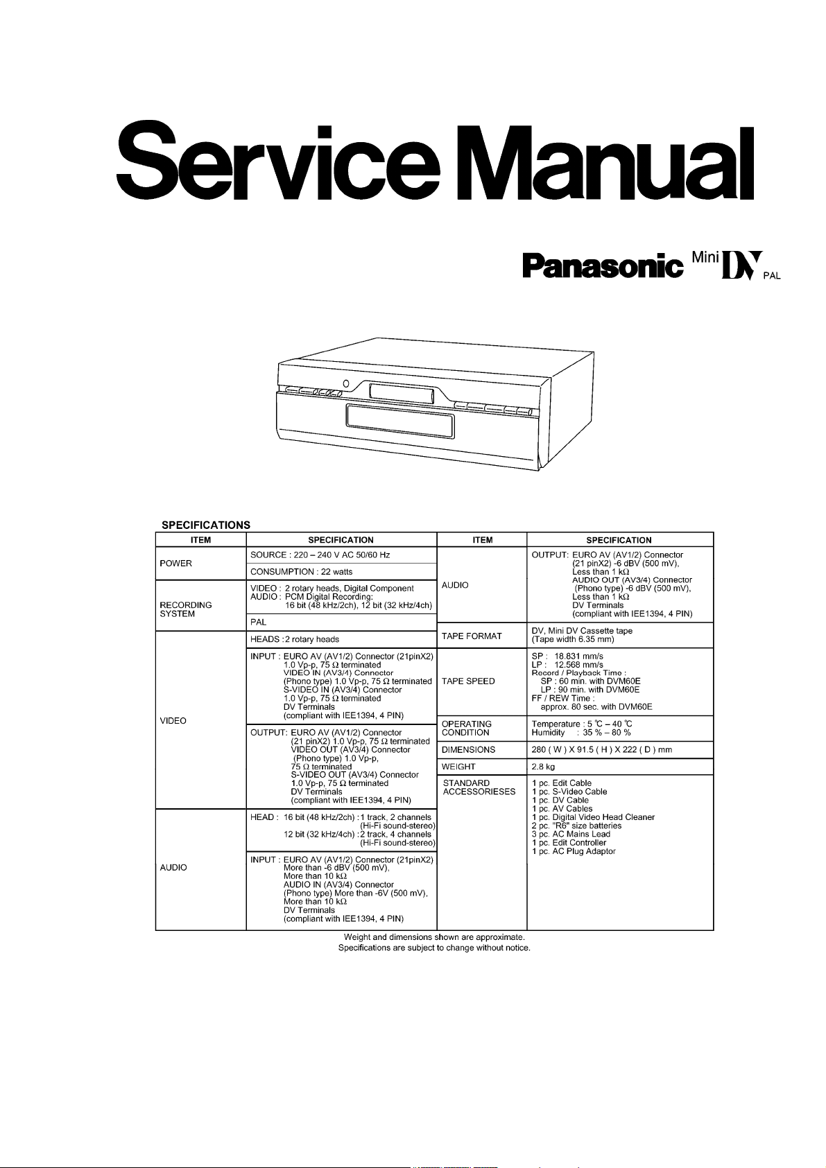
1 VFK1507P ANALOG Y/C Connection
C.B.A.
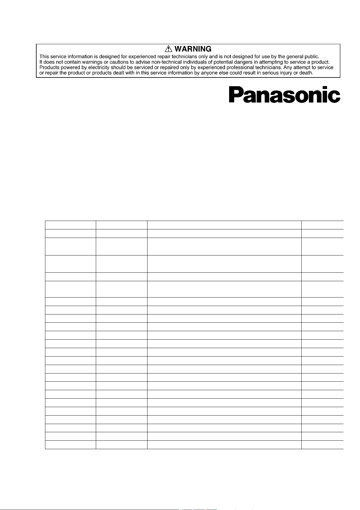
2 VFK1509 36P Flat Cable
3 VFK1508 32P Flat Cable
4 VFK1509 36P Flat Cable
5 VFK1174 30P Flat Cable
6 VFK1284 24P Flat Cable
7 VFK1292 9P Flat Cable
8 VFK1282 22P Flat Cable
9 VFK1446 32P Flat Cable
10 VFK1445 26P Flat Cable
11 VFK1527 3P Extension Cable
12 VFK1529 2P Extension Cable
13 VFK1530 30P Flat Cable Mech. Flex. (VES0914) 1 for Emagency Tape
Main C.B.A.→ Analog Y/C
C.B.A.
Main FP3401→ Digital FP3201
Main FP3402→ Digital FP3202
Main FP6201→ Digital FP6002
Digital FP6003→ Mech. Flex.
(VES0914)
Digital FP3203→ Mech. (Head
Amp)
Digital P2501→ Mech.
(Cylinder)
Digital P2502→ Mech.
(Capstan)
Main P7901→ Timer P7502
Main P7902→ Timer P7501
Digital P6001→ Switch P1502
Digital P6002→ Motor P1501
Q‘ty
1
1
1
1
1
1
1
1
1
1
1
1
Ejection
Remarks
Fig. 2-1 Extension Cable
2.1.2. Service Position
2.1.2.1. Service Position for Analog Y/C C.B.A.
Fig. 2-2 Service Position for Analog Y/C C.B.A.
Page 4
http://cxema.ru
2.1.2.2. Service Position for Digital C.B.A.
When checking the Digital C.B.A., remove the Mechanism unit with Digital C.B.A. from the frame. Then,
connect the extension cables as shown in
Mechanism unit.
Fig. 2-3 Service Position for Digital C.B.A.
Fig. 2-3 Service Position for Digital C.B.A. and turn overthe
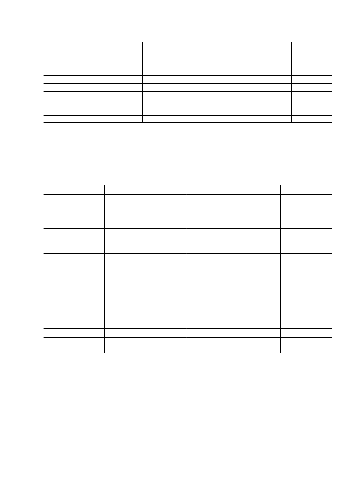
2.1.2.3. Service Position for Main C.B.A.
When checking the Main C.B.A., take out the Mechanism unit with Digital C.B.A. and Main C.B.A. from the
frame. Then, connect extension cables as shown in
Main C.B.A..
Fig. 2-4 Service Position for Main C.B.A. and turnover the
Fig. 2-4 Service Position for Main C.B.A.
Page 5
http://cxema.ru
2.2. SERVICE MODE
e
a
e
S
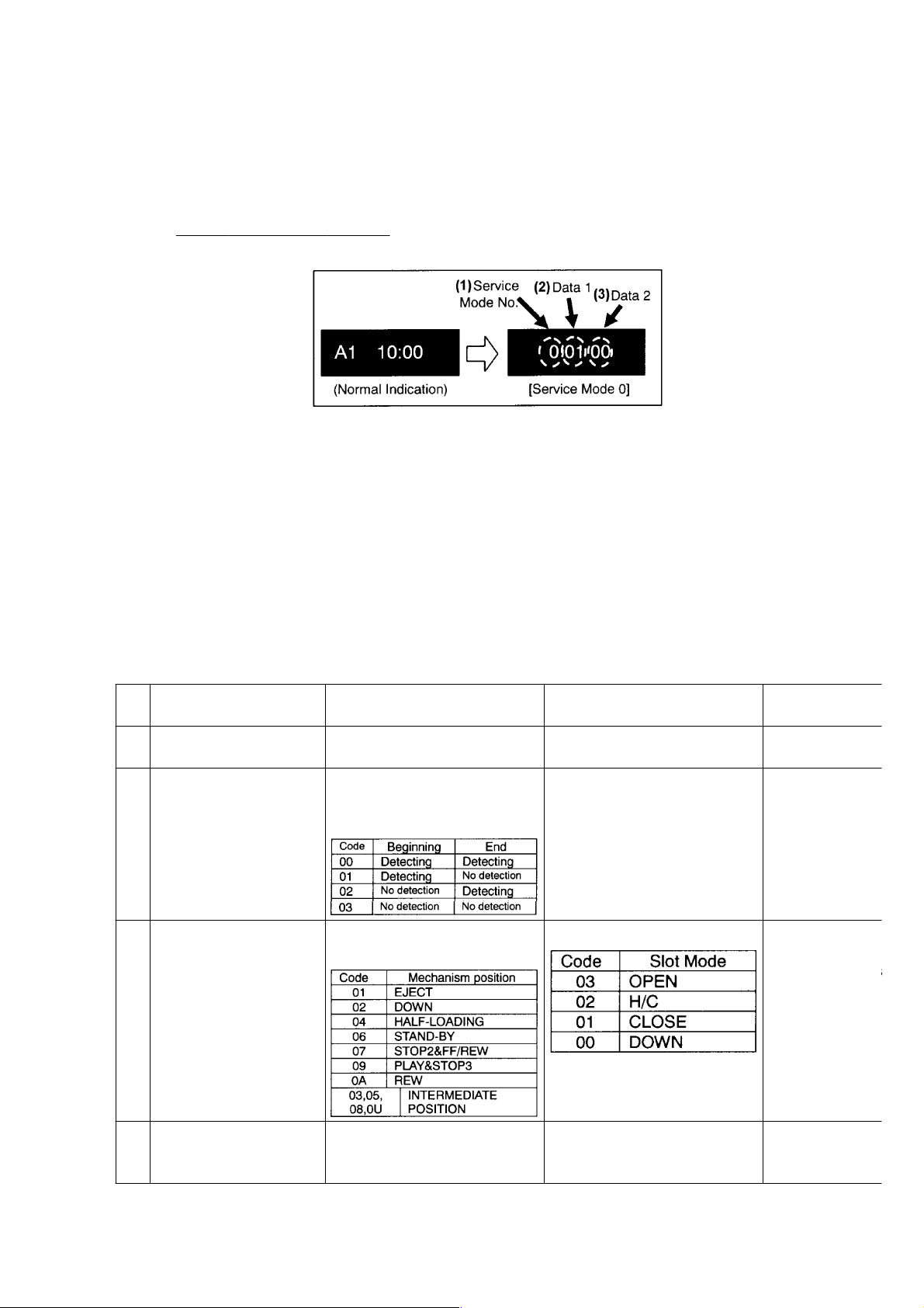
2.2.1. Setting the Service Mode
This VTR is equipped with the Service Mode, which is effective for servicing.To turn on the Service Mode,
press FF and EJECT button simultaneously in 3 seconds.(Indication of Front Panel Display is changed as
shown in
2.2.2. How to use the Service Mode
There are 8 kinds of Service Mode and the subject of each Service Mode is listed below.
Mode 0: Mevhanism process/position
Mode 1: Tape Beg/End Sensor& Receiving key command
Mode 2: Mechanism position& slot mode
Mode 3: Self-Diagnosed record 1 (Latest)
Mode 4: Self-Diagnosed record 2 (2nd Latest)
Mode 5: Self-Diagnosed record 3 (3rd Latest)
Mode 6: Receiving command at LSI
Mode 7: Mechanism Manual operation
The following chart shows the meaning of the each code.
To read/decode the Service Mode, use following chart.
Fig.2-5 Service Mode (Sample).)
Fig. 2-5 Service Mode (Sample)
(1)
No.
0 Mechanism position. VCR (Deck) Mode [Real-time] Mechanism driving position
1 Tape Beg/End sensor
checkup& Receiving
key Command checkup
2 Mechanism position&
slot mode checkup
3 Self-Diagnosed record 1
(Latest)
Group (2) Data 1 (3) Data 2 Remarks
process code. [Real-time]
Tape Beginning/End Detection
data.
[Real-time]
Mechanism position
[Real-time]
Refer to the Fig. 2-8
Receiving Key command from
both Remote controller& VCR.
[Real-time]
Slot mode [Real-time]
These two digits (Data2) are
meaningless although it might
be changed.
At this mode, wh
the Eject key is
pressed mode th
3 seconds, it will
the Electrical
Adjustment Mod
Refer to the
SELFDIAGNOSI
MODE.
Page 6
http://cxema.ru
(1)
S
S
Group (2) Data 1 (3) Data 2 Remarks
No.
4 Self-Diagnosed record 2
(2nd Latest)
5 Self-Diagnosed record 3
(3rd Latest)
(To be continued.)
Refer to the Fig. 2-8
Refer to the Fig. 2-8
These two digits (Data2) are
meaningless although it might
be changed.
These two digits (Data2) are
meaningless although it might
be changed.
Refer to the
SELFDIAGNOSI
MODE.
Refer to the
SELFDIAGNOSI
MODE.
(1)
Group (2) Data 1 (3) Data 2 Remarks
No.
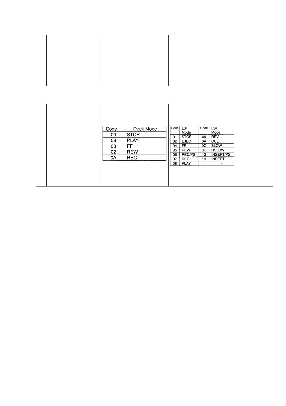
6 LSI receiving command
Deck Mode LSI Mode [Real-time]
checkup
7 Mechanism Manual
operation
Mechanism Position
(Real-time) (Same data with
Slot mode (Real-time (Same
data with Service Mode 2)
Service Mode 2)
Fig. 2-6 Service Mode Decoding Table
2.2.3. Self- Diagnosis Mode
This VTR has a Self-Diagnosis function, which detects troubles when undesirable condition occurred.When
one of the following listed trouble is detected, Power is automatically turns off and its error is saved as the
"Error-Code" in Timer microprocessor (IC7501).(Threeerror codes can be memorized in historical order and
are backed up by the Lithium Battery;B7901.)
NOTE:
It is not automatically displayed on the Front Panel Display although trouble has been detected. (It means that user can
not be recognized what is happened.)
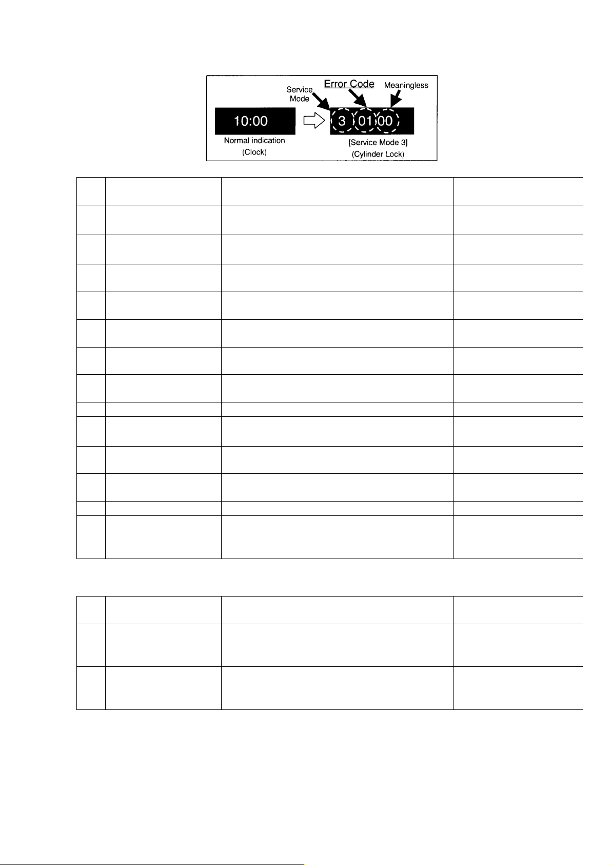
2.2.3.1. How To Confirm The "Error Code".
The Error Code can be confirmed on the Front Panel Display by placing the unit to the Service Mode 3, 4
and/or 5.
1. Turn on the Service Mode by pressing "FF" and "EJECT" buttons simultaneously in more than 3 seconds.
2. Select the Service Mode 3, 4 or 5 by pressing the "FF" and "EJECT" buttons simultaneously in certain time.The error
codes can be displayed Service Mode 3, 4 and 5 in historical order.
Service Mode 3 displays the last Error Code on the FIP.
Service Mode 4 displays the Error Code on the FIP, which is just before the error code displayed in Service Mode 3.
Service Mode 5 displays the Error Code on the FIP, which is just before the error code displayed in Service Mode 4.
NOTE:
Although same errors are occurred in several times, only first error code is memorized.(When the error is occurred, it is
compared with the memorized data. If the just occurred error is same as the memorized one, it is skipped to be
memorizing.)
Fig. 2-7 Error Code is displayed in F.I.P. (Example)
Page 7
http://cxema.ru
Error
Code
01 Cylinder Lock The cylinder does not rotate or Cylinder lock has
02 Capstan Lock FG signal does not existed in the Cassette down
03 Loading Lock Mechanism Lock has been detected during
04 Unloading Lock Mechanism Lock has been detected during
05 Reel FG NG Abnormal Reel FG has been detected during
07 Slot Motor Lock Slot motor lock has been detected during slot
09 Communication Error
(Sys-Timer)
11 Head Clogging Head clogging has been detected. Head cleaning
14 Mode error Cassette down position has been detected during
17 S-Reel Lock S-Reel Lock has been detected during normal
18 T-Reel Lock T-Reel Lock has been detected during normal
19 Fan Motor Lock Fan motor does not rotate after turning power ON. Fan motor
51 S-Photo Tr Adj. Error
Condition Description Remedy/Check
Check the Cylinder
been detected during normal rotation.
position (Eject-Rev.).
loading operation.
unloading operation.
loading/unloading operation.
in/out operation.
"SYSCON-TIMER" Communication error has
been detected.
unloading operation.
rotation.
rotation.
Adjustment Error.
(Adjustment error of S-Photo Transistor sensitivity
Adjustment.)
Cylinder Drive IC
Check the Capstan
Capstan Drive IC
Loading Post
Loading Post
Reel FG line
Slot Motor
Communication-line
Loading Motor Drive
Mode Switch
S-Reel
T-Reel
Re-adjustment is required.
(Tape End Sensor
Adjustment.)
(To be continued.)
Error
Code
52 T-Photo Tr Adj. Error
53 S/T-Photo Tr Adj. Error
Fig. 2-8 Error Code (Displayed in Service Mode 3, 4 and 5)
2.2.4. Emergency Tape Ejection
If the electric circuit defects and no Tape ejection can be made in regular way, try following methods.There are
two methods to achieve the emergency tape ejection.
Condition Description Remedy/Check
Adjustment Error.
(Adjustment error of T-Photo Transistor sensitivity
Adjustment.)
Adjustment Error.
(Adjustment error of S/T-Photo Transistor
sensitivity Adjustment.)
Re-adjustment is required.
(Tape Beg. Sensor
Adjustment.)
Re-adjustment is required.
(Tape End/Beg. Sensor
Adjustment.)
Page 8
http://cxema.ru
1. Utilizing the Service Mode 7.
2. Utilizing the Extra DC power (batteries).
2.2.4.1. Utilizing the Service Mode 7
Procedures:
1. Remove the Top panel.
[Refer to the "Disassembly Procedures" section.]
2. Turn on the Service mode and select mode 7.
[Refer to the "Service Mode" section.]
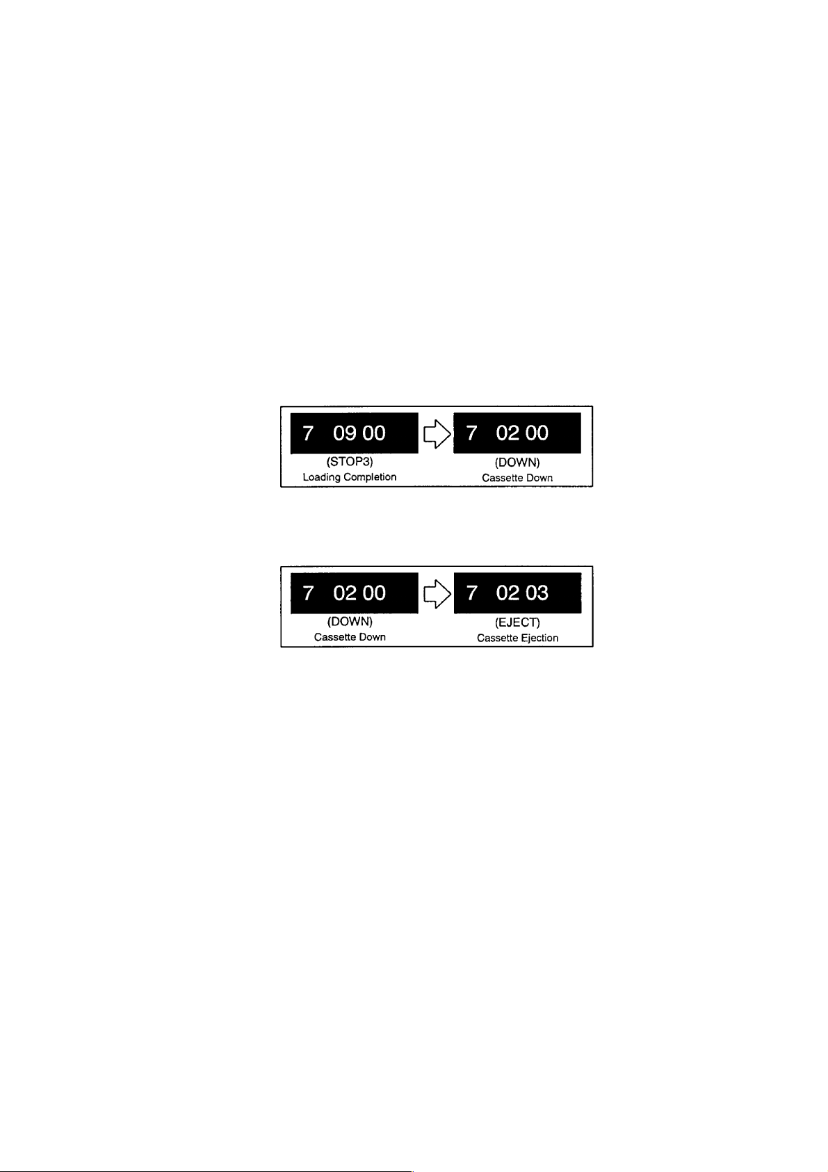
In this mode, when the "STOP" button is pressed, loading motor rotates unloading direction.
Also when the "PLAY" button is pressed, loading motor rotates loading direction.
This action is effective only while either "STOP" or "PLAY" button is being pressed.
NOTE:
While loading/unloading operation, pay attention to the tape slack.
3. Press the "STOP" button until "7 02 00"(Cassette Down position) is displayed on the F.I.P. display.
Fig. 2-9
4. Be sure to confirm no tape slack and take up the tape slack by rotating Capstan with hand if necessarily.
5. Press the "STOP" button until "7 02 03"(Cassette Eject position) is displayed on the F.I.P. display.
Fig. 2-10
6. Take out the tape carefully.
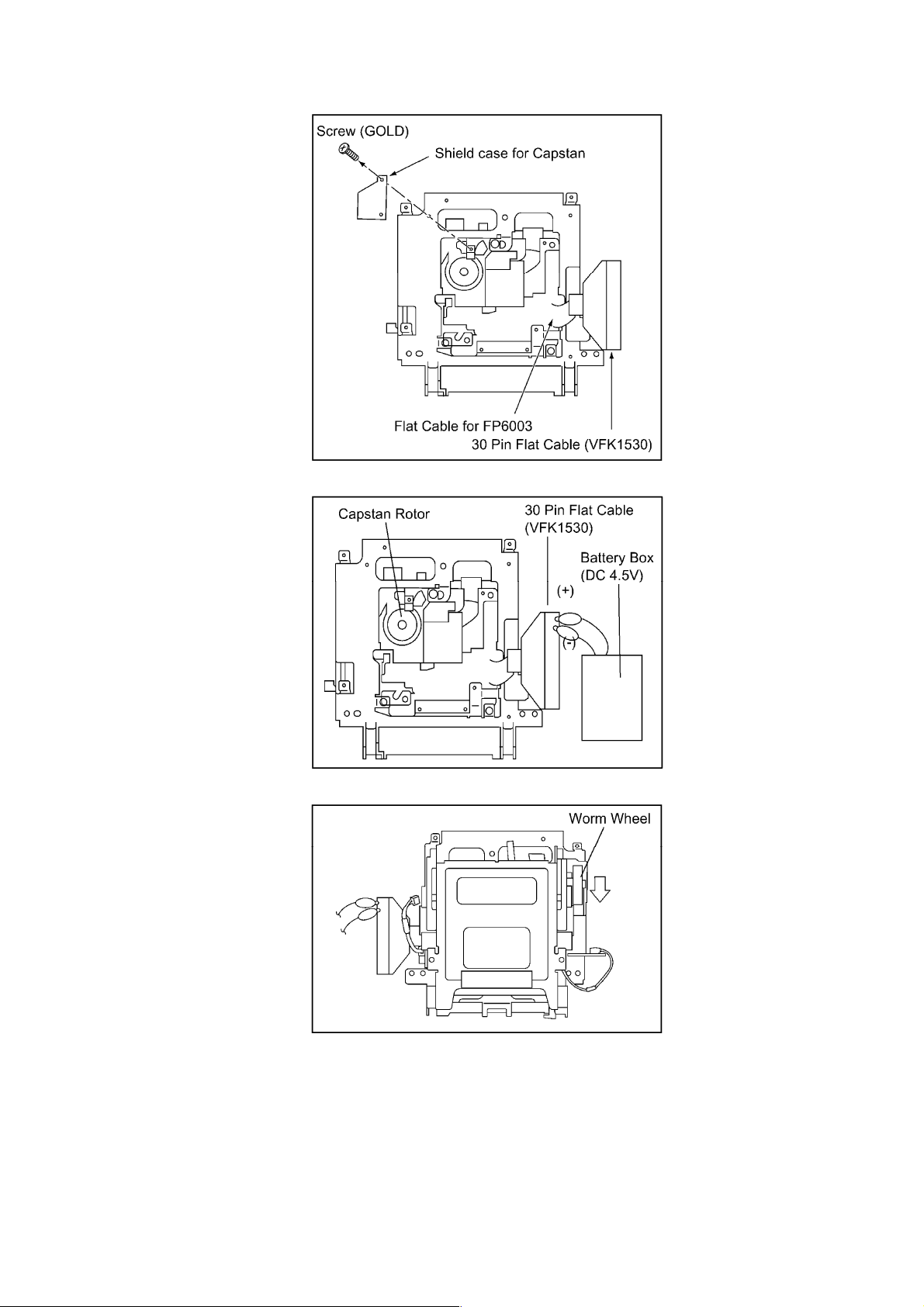
2.2.4.2. Utilizing the Extra DC power (batteries)
Procedures:
1. Remove the Mechanism unit from the chassis.
[Refer to the "Disassembly Procedures" section.]
2. Remove the Digital C.B.A. from the Mechanism unit.
3. Remove the shield case of capstan unit.
4. Connect the Flexible card (VFK1530).
5. Supply the+B (4.5V) to VFK1530 to activate the unloading operation.
Loading.............Pin25,26 (+4.5V) Pin27,28 (GND)
Unloading.........Pin25,26 (GND) Pin27,28 (+4.5V)
In this case, stop supplying the power at just before the mechanism to be the unloading complete position (Tension post
is not retracted fully), otherwise, the tape slack can not be taken although capstan is rotated with hand.
6. Confirm that no tape slack and supply the power again to make full unloading position (Tension post is retracted fully).
Take up the tape slack by rotating Capstan with hand if necessarily.
7. Rotate the worm wheel with hand in counterclockwise, then take out the tape carefully.
Fig. 2-11
Page 9
http://cxema.ru
Fig. 2-12
Fig. 2-13
2.3. OPERATING GUIDE
2.4. CAUTION FOR AC MAINS LEAD (FOR UK)
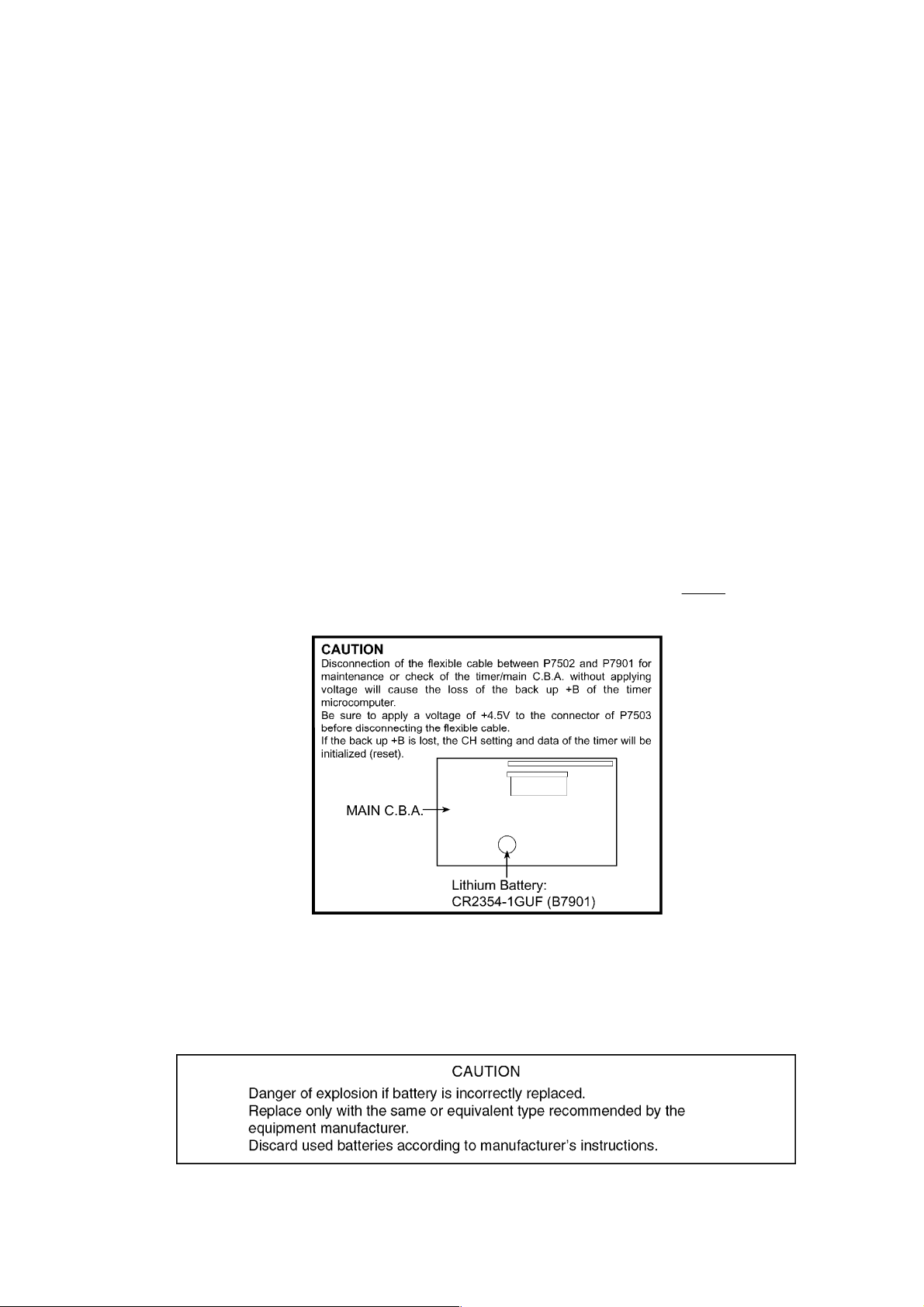
2.5. HOW TO REPLACE THE LITHIUM BATTERY
Page 10
http://cxema.ru
2.5.1. Backup Battery B7901
This VTR equipped with the Backup Battery (B7901) to backup the following memorized data in the Timer
microprocessor (IC7501).
1. Setting condition of "VCR Functions"
OSD(AUTO/ON/OFF)
VCR display(ON/OFF/DIMMED)
Colour Mode(COLOUR/ B/W)
Comb filter (ON/OFF)
E-TBC (ON/OFF)
REC-DNR (LEVEL1/LEVEL2)
PB-DNR (LEVEL1/LEVEL2)
Remote (VCR1/VCR2/VCR3)
2. Setting condition of "Edit Functions"
Search with Sound (OFF/EDIT ONLY/ALWAYS ON)
Audio Mode(12bit/16bit)
One-Touch-Edit(OFF/ON)
Still Album(3-20seconds adjustable)
3. Clock& Date data
4. Self-Diagnosed Result Record (3 records)
2.5.2. Replacement Procedure
1. Remove the Top Panel and Mechanism unit with DIGITAL C.B.A.(VEP03F39A).(Refer to Disassembly Procedures).
2. Unsolder the Lithium Battery;B7901"CR2354-1GUF" and then replace it into new one.(See
Fig. B1)
Fig. B1
CAUTION:
The lithium battery is a critical component (Type No.: CR2354-1GUF Manufactured by Panasonic.) / It must never be
subjected to excessive heat or discharge. / It must therefore only be fitted in equipment designed specifically for its use. /
Replacementbatteries must be of the same type and manufacture. / They must be fitted in the same manner and location
as the original battery, with the correct polarity contacts observed. / Do not attempt to re-charge the old battery or re-use it
for any otherpurpose. / It should be disposed of in waste products destined for burial rather than incineration.
Page 11
http://cxema.ru
3. ADJUSTMENT PROCEDURES
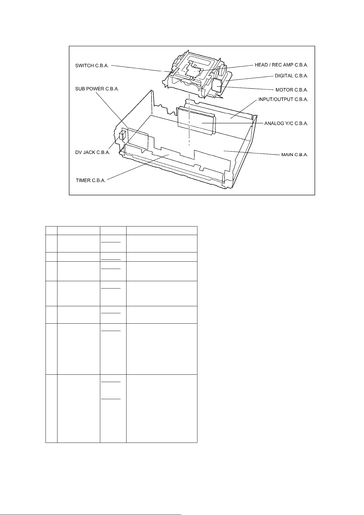
3.1. DISASSEMBLY/ ASSEMBLY PROCEDURES FOR CABINET PARTS,
C.B.A. AND MECHANISM UNIT
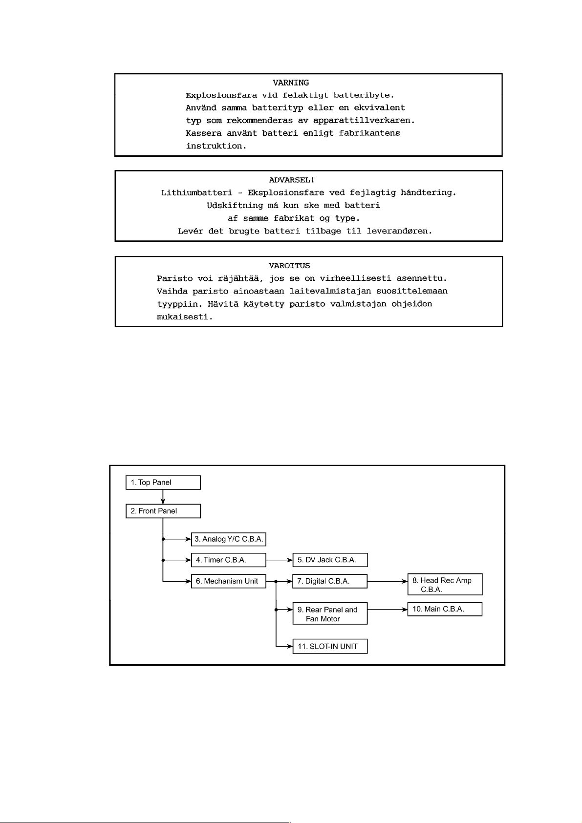
3.1.1. Disassemble Flow Chart for cabinet parts, C.B.A. and Mechanism Unit.
This flow chart indicates the disassembly steps the cabinet parts, C.B.A. and Mechanism Unit in order to
access to items to be serviced. When reinstalling, perform the steps in reverse order.
Fig. 3-1 Flow Chart
Fig. 3-2
Page 12
http://cxema.ru
3.1.2. Assemble/ Disassemble Procedures (for cabinet parts, C.B.A. and Mechanism
Unit)
No. ITEM/PART FIGURE REMARKS
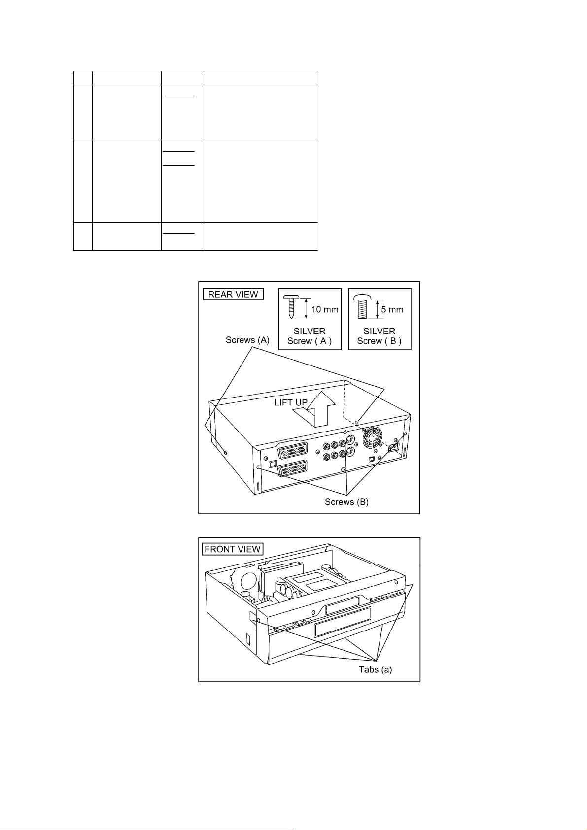
1 Top Panel
2 Front Panel
3 Analog Y/C
C.B.A.
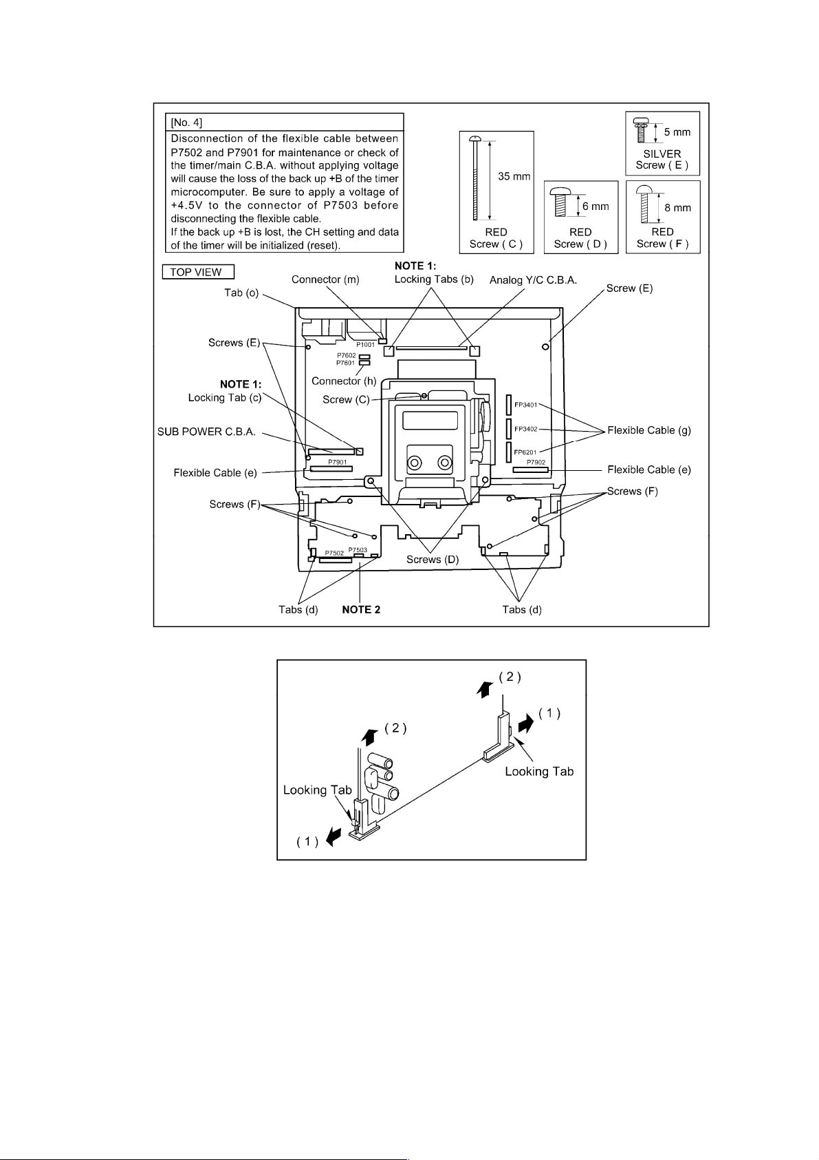
4 Timer C.B.A
5 DV Jack
C.B.A.
6 Mechanism
Unit
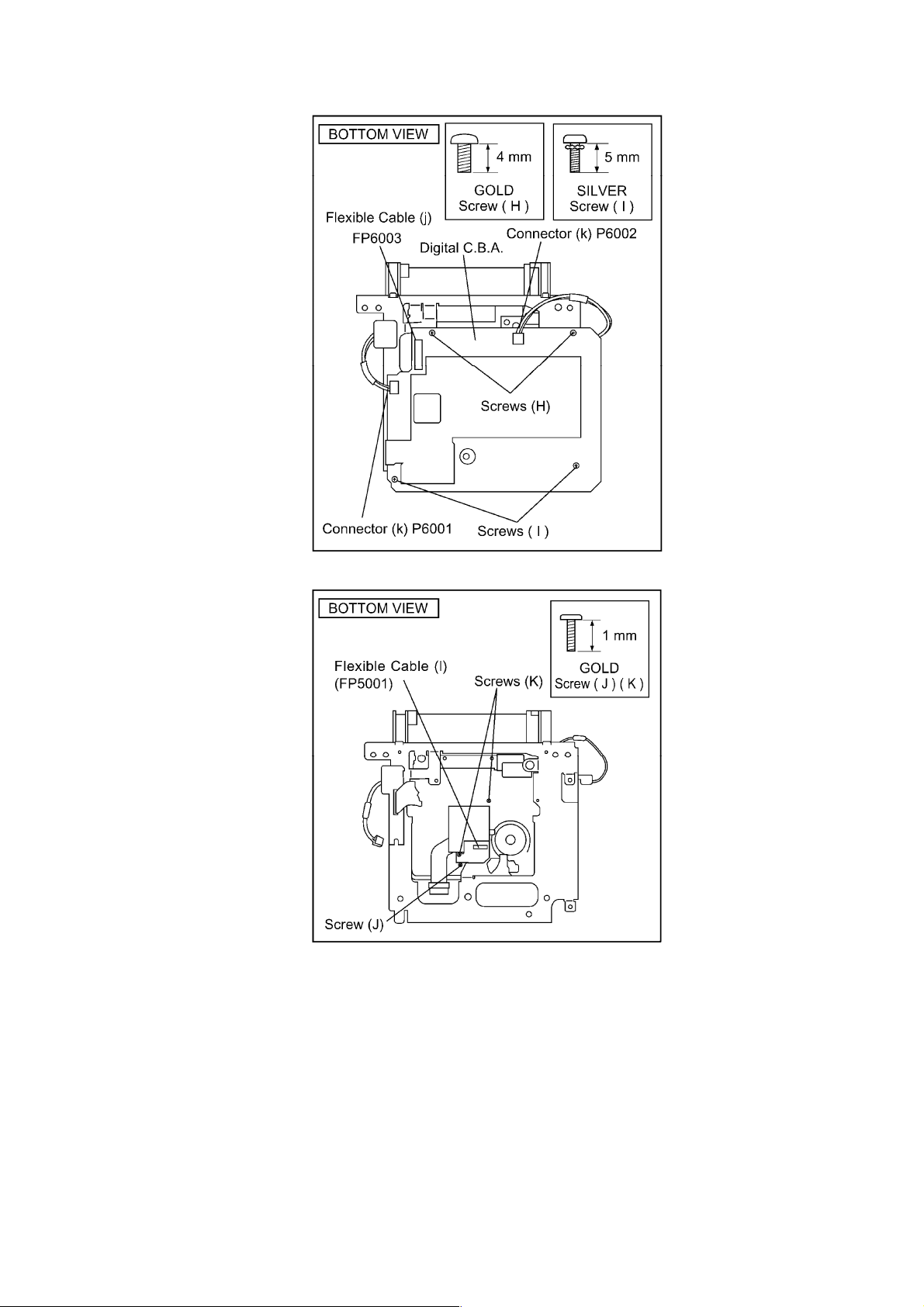
7 Digital C.B.A.
Fig. D1 2-Screws (A)
3-Screws (B)
Fig. D2
Fig. D3
Fig. D3 6-Screws (F) / 5-Tabs
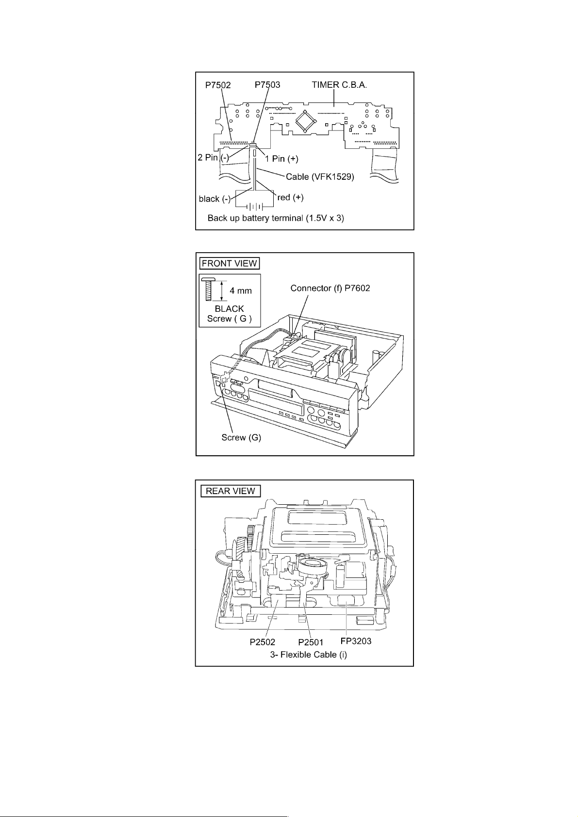
Fig. D4 1-Connector (f) (P7602)
Fig. D3 3-Flexible Cable (g)
Fig. D5
Fig. D6
5-Tabs (a)
Note1:
2-Locking Tabs (b)
(d) / 2-Flexible Cable (e)
/ (P7901, P7902)
1-Screw (G)
(FP3401, FP3402,
FP6201)
1-Screw (C)
2-Screws (D)
1-Connector (h) (P7601)
3-Flexible Cable (i)
(FP3203, P2501, P2502)
2-Screws (H)
2-Screws (I)
1-Flexible Cable (j)
(FP6003)
2-Connectors (k)
(P6001, P6002)
Page 13
http://cxema.ru
No. ITEM/PART FIGURE REMARKS
8 Head Rec
Amp C.B.A.
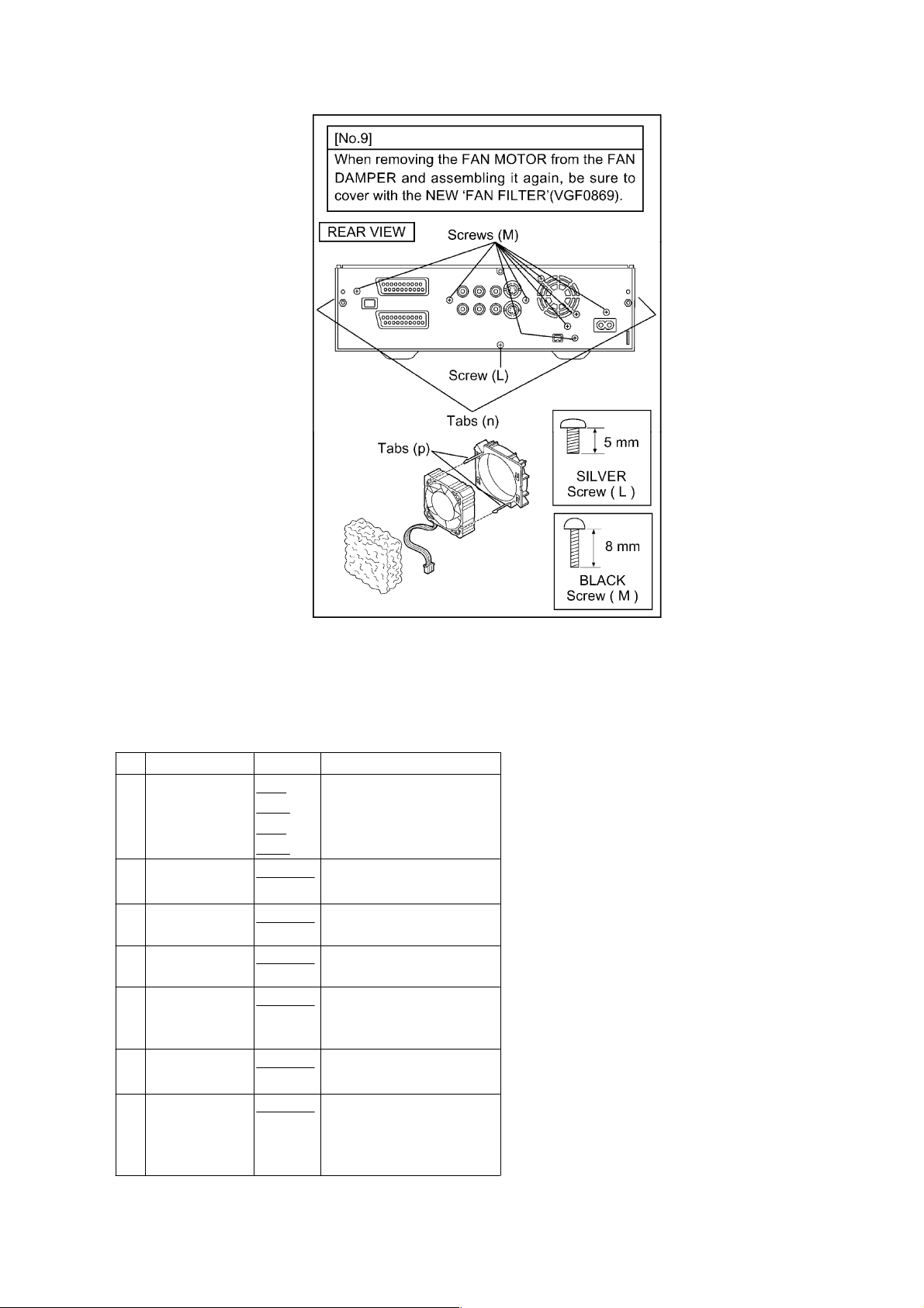
9 Rear Panel
and Fan Motor
10 Main C.B.A.
Fig. D7 1-Screw (J)
2-Screws (K)
1-Flexible Cable (l)
(FP5001)
Fig. D3
Fig. D8
Fig. D3 3-Screws (E)
1-Connector (m)
(P1001)
1-Screw (L)
7-Screws (M)
2-Tabs (n)
2-Tabs (p)
1-Tabs (o)
Fig. D1
Fig. D2
Fig. D3
Page 14
http://cxema.ru
NOTE 1
NOTE 2
Page 15
http://cxema.ru
Fig. D4
Fig. D5
Fig. D6
Page 16
http://cxema.ru
Fig. D7
Fig. D8
Page 17
http://cxema.ru
3.1.3. Assemble/ Disassemble Procedures of Slot-in Unit
3.1.3.1. Disassemble Section
Before proceeding the disassembling of the Slot-in unit, remove the mechanism unit from the chassis and
remove the DIGITAL C.B.A. from the mechanism by referring the disassemble procedure describing in the
previous section.
No. ITEM/PART FIGURE REMARKS
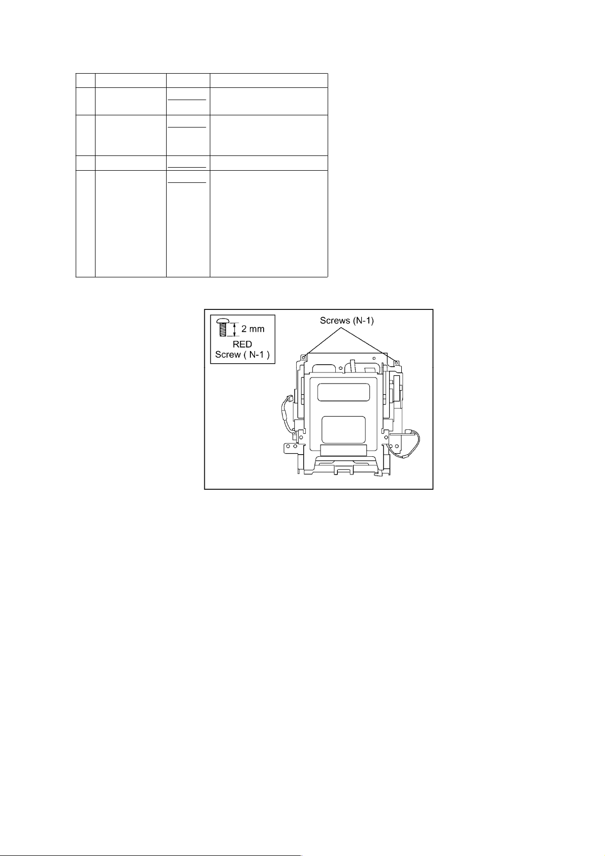
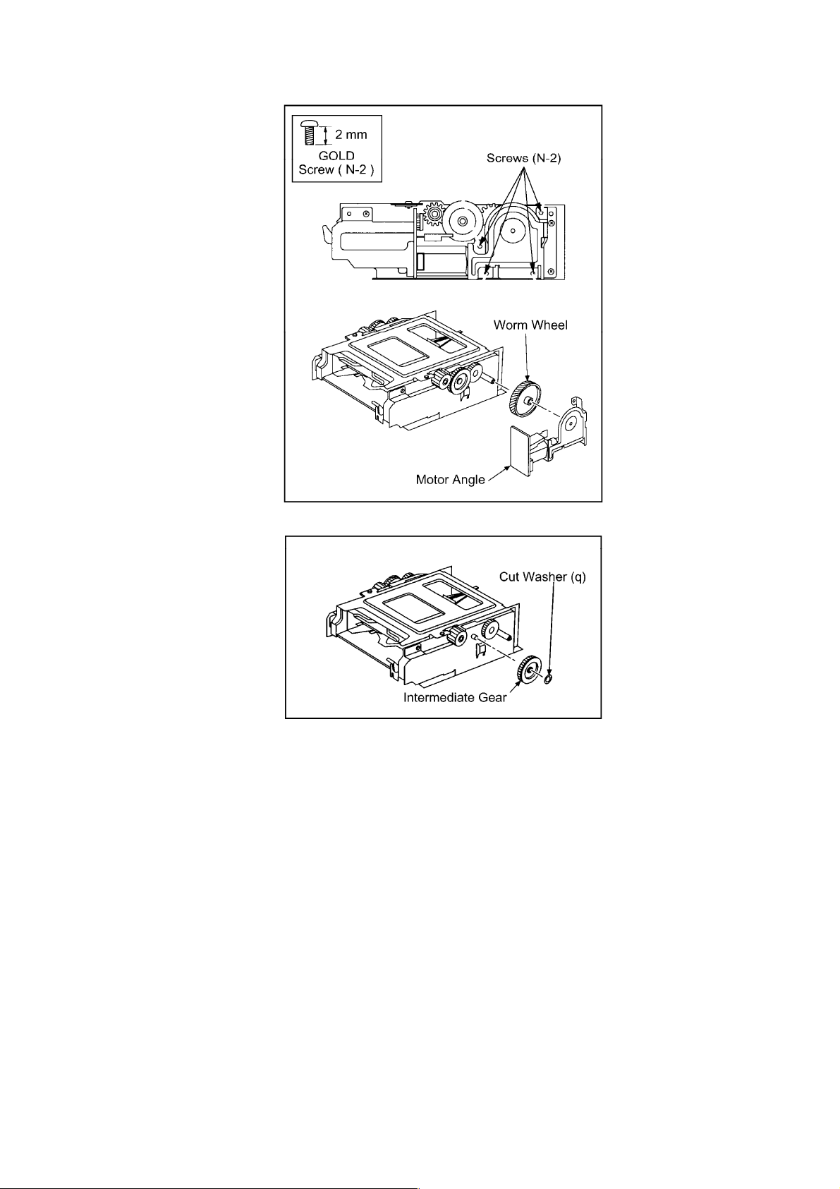
11 SLOT-IN
UNIT/MOTOR
ANGLE/WORM
WHEEL
12
INTERMEDIATE
GEAR
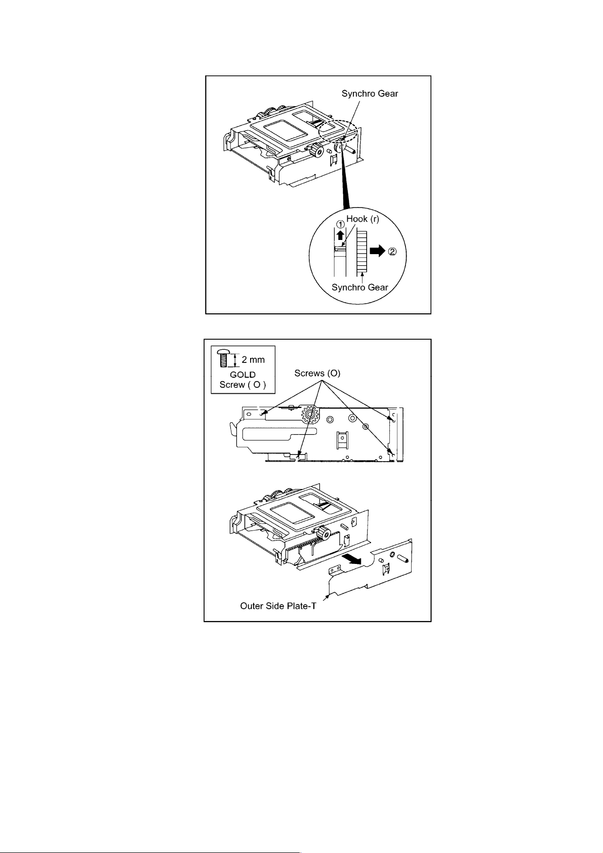
13 SYNCHRO
-GEAR
14 OUTER SIDE
PLATE-T
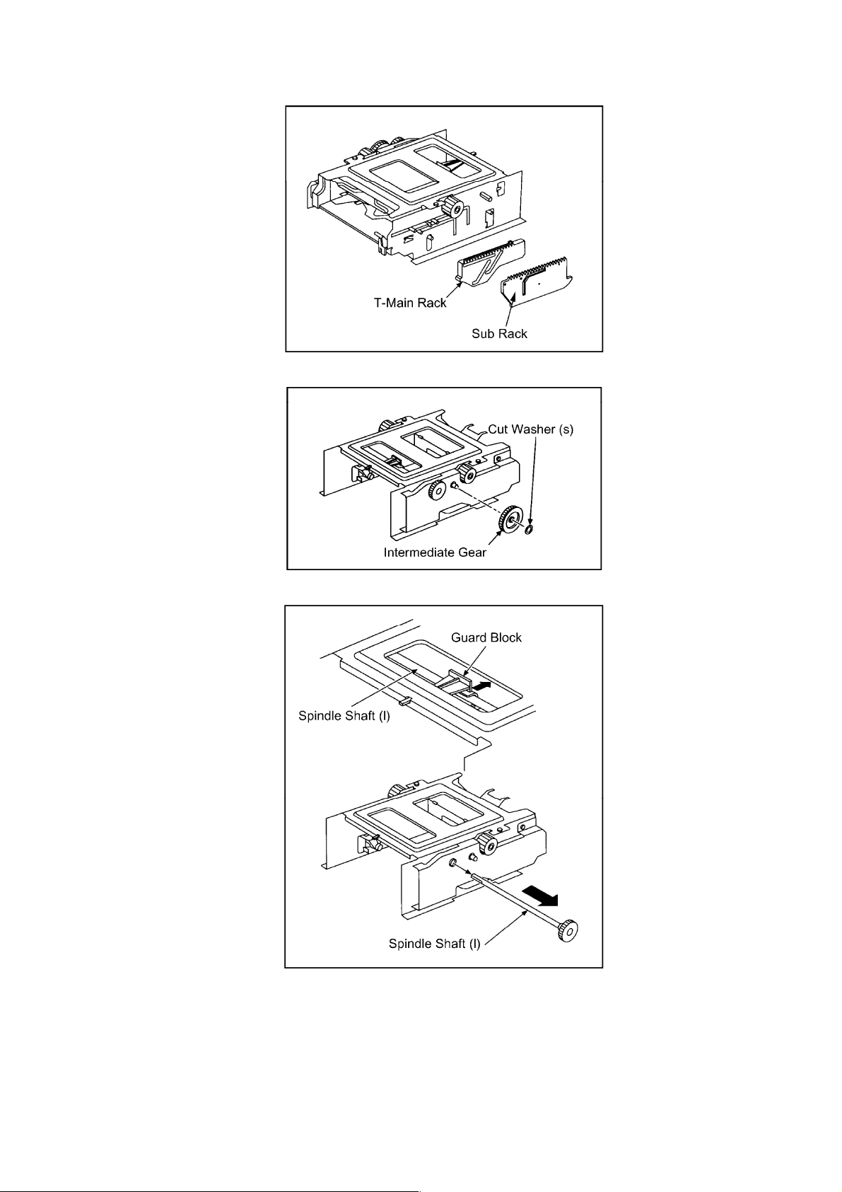
15 SUB
RACK/T-MAIN
RACK
16
INTERMEDIATE
GEAR
17 GUARD
BLOCK /
SPINDLE
SHAFT (I)
Fig.
D9-1
Fig.
D9-2
Fig. D10
Fig. D11
Fig. D12
Fig. D13
Fig. D14
Fig. D15
2-Screws (N-1)
4-Screws (N-2)
1-Cut washer (q)
1-Hook (r)
4-Screws (O)
1-Cut washer (s)
Slide the guard block to
arrow direction.
Page 18
http://cxema.ru
No. ITEM/PART FIGURE REMARKS
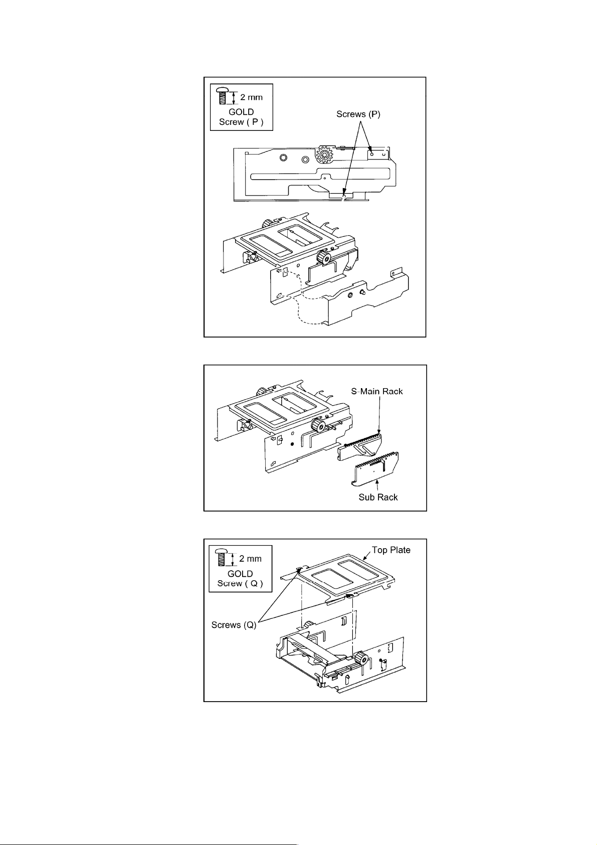
18 OUTER SIDE
PLATE-S
19 SUB
RACK/S-MAIN
RACK
20 TOP PLATE
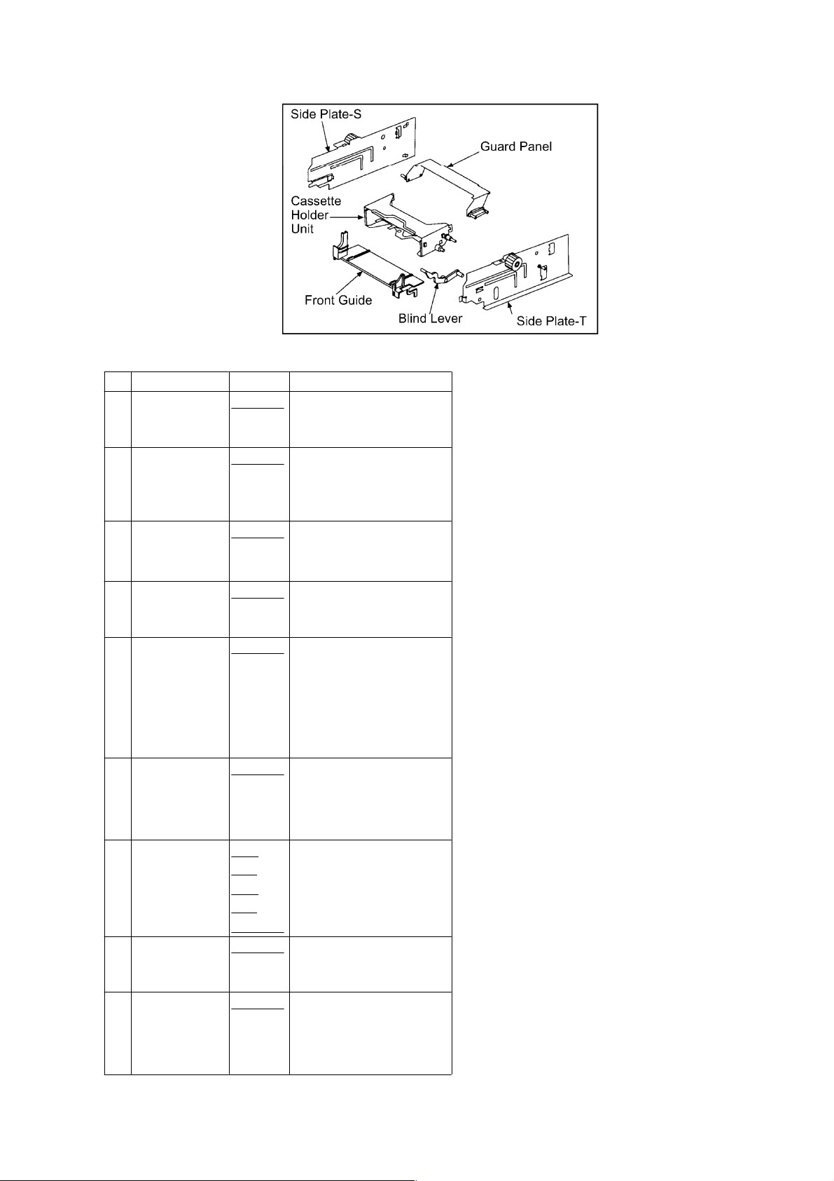
21 SIDE PLATE
S& T/GUARD
PANEL /
CASSETTE
HOLDER
UNIT/FRONT
GUIDE/BLIND
LEVER
Fig. D16
Fig. D17
Fig. D18
Fig. D19
2-Screws (P)
2-Screws (Q)
Fig. D9-1
Fig. D9-2
Page 19
http://cxema.ru
Fig. D10
Fig. D11
Page 20
http://cxema.ru
Fig. D12
Fig. D13
Page 21
http://cxema.ru
Fig. D14
Fig. D15
Fig. D16
Page 22
http://cxema.ru
Fig. D17
Fig. D18
Fig. D19
Page 23
http://cxema.ru
3.1.3.2. Assemble Section
No. ITEM/PART FIGURE REMARKS
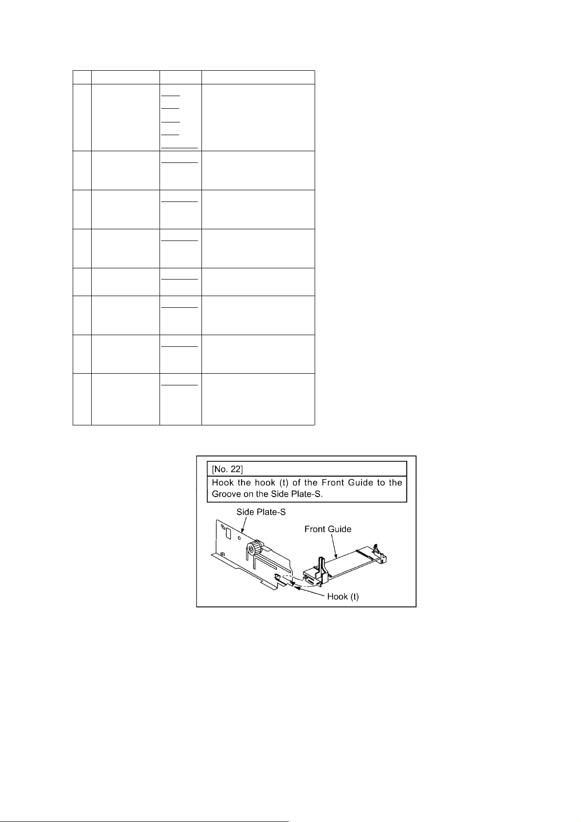
22 FRONT
GUIDE/SIDE
PLATE-S
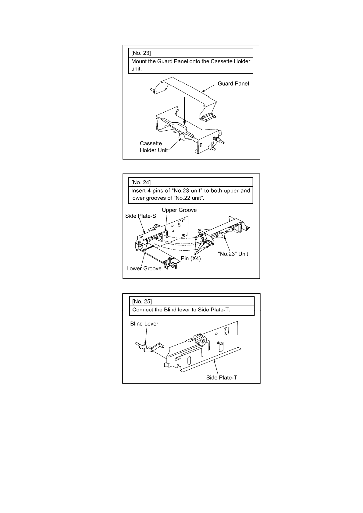
23 CASSETTE
HOLDER
UNIT/GUARD
PANEL
24 "No.22"
unit/"No.23"
unit
25 SIDE
PLATE-T/BLIND
LEVER
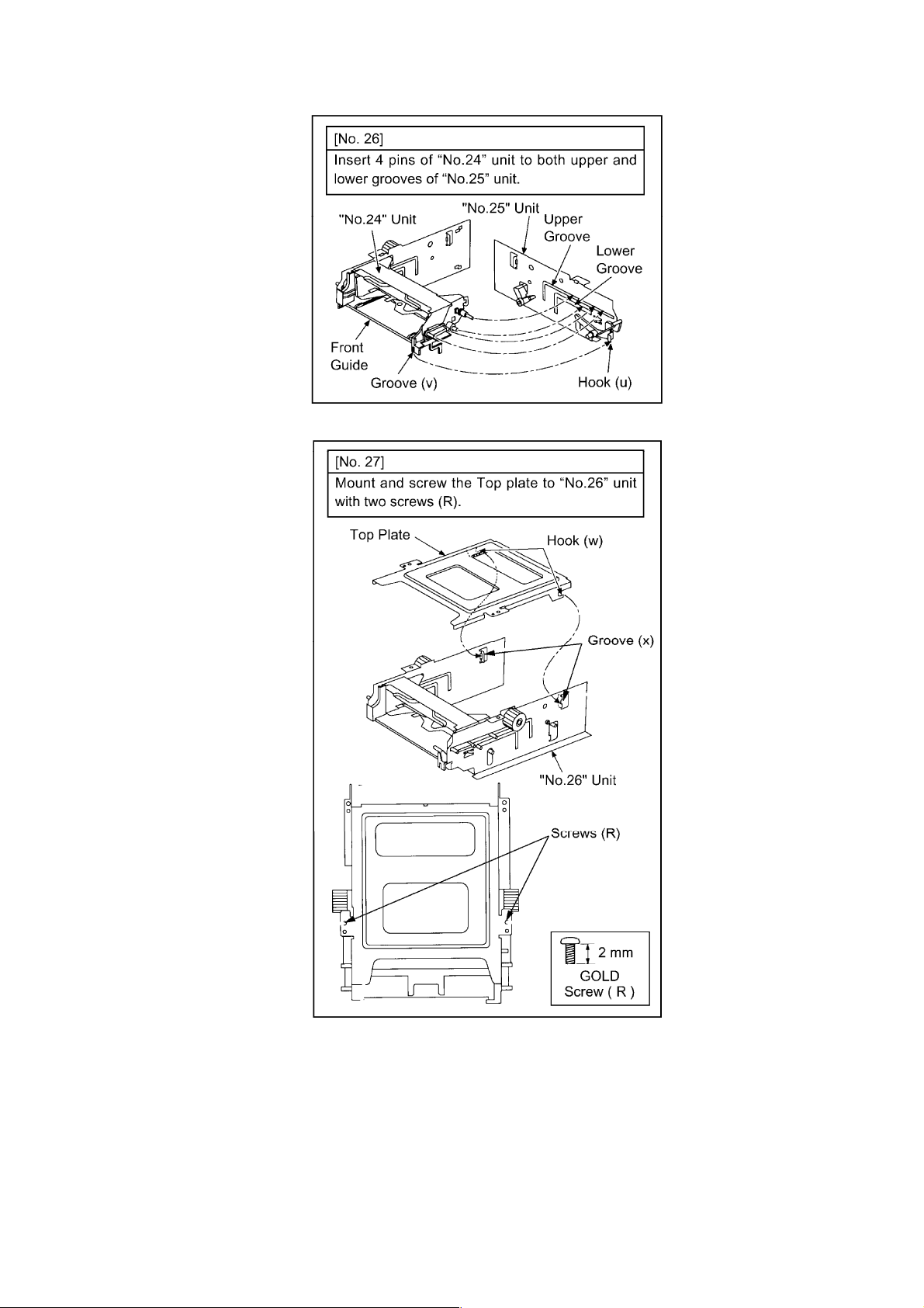
26 "No.24"
unit/"No.25"
unit
27 "No.26"
unit/TOP
PLATE
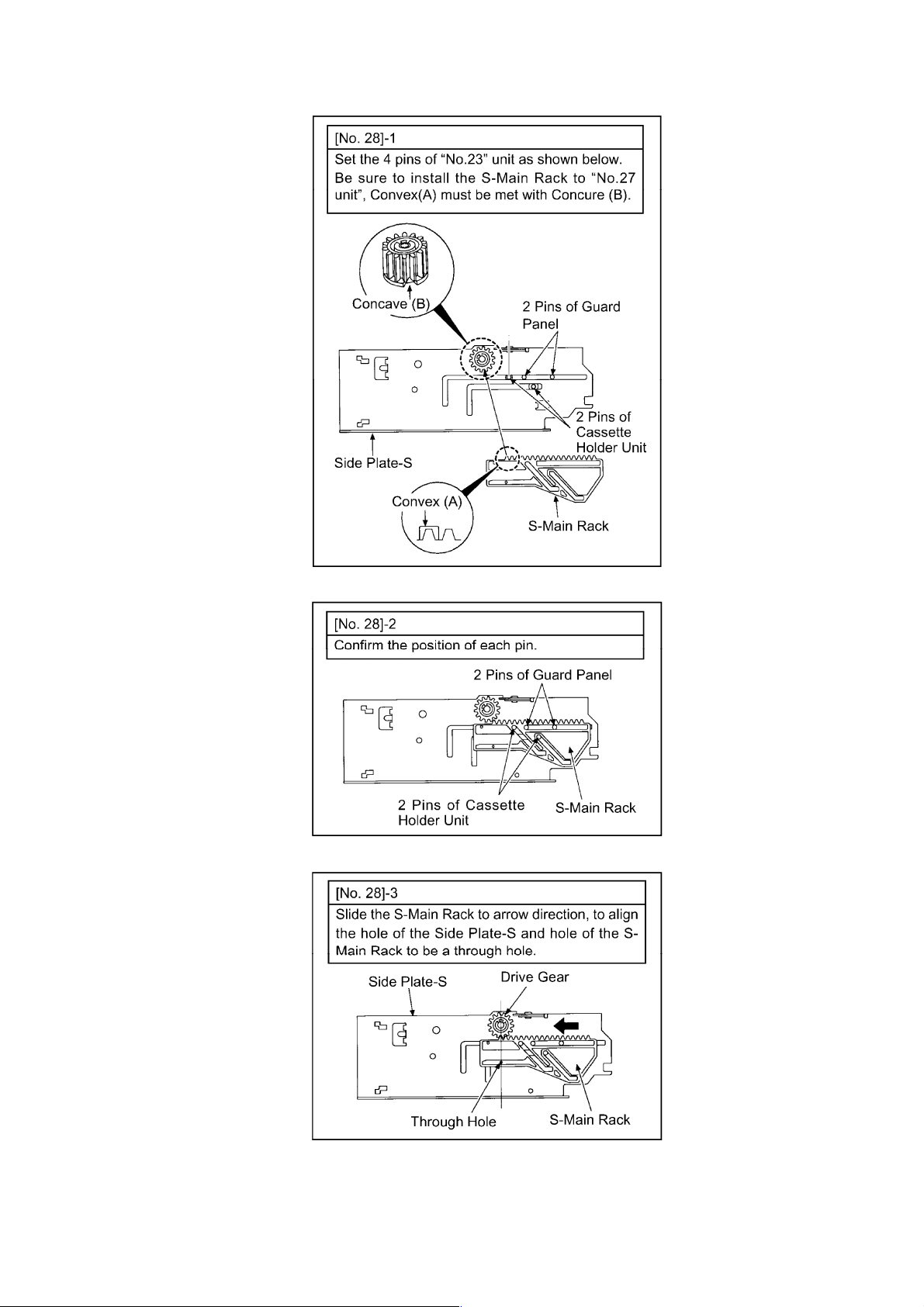
28 "No.27"
unit/S-MAIN
RACK
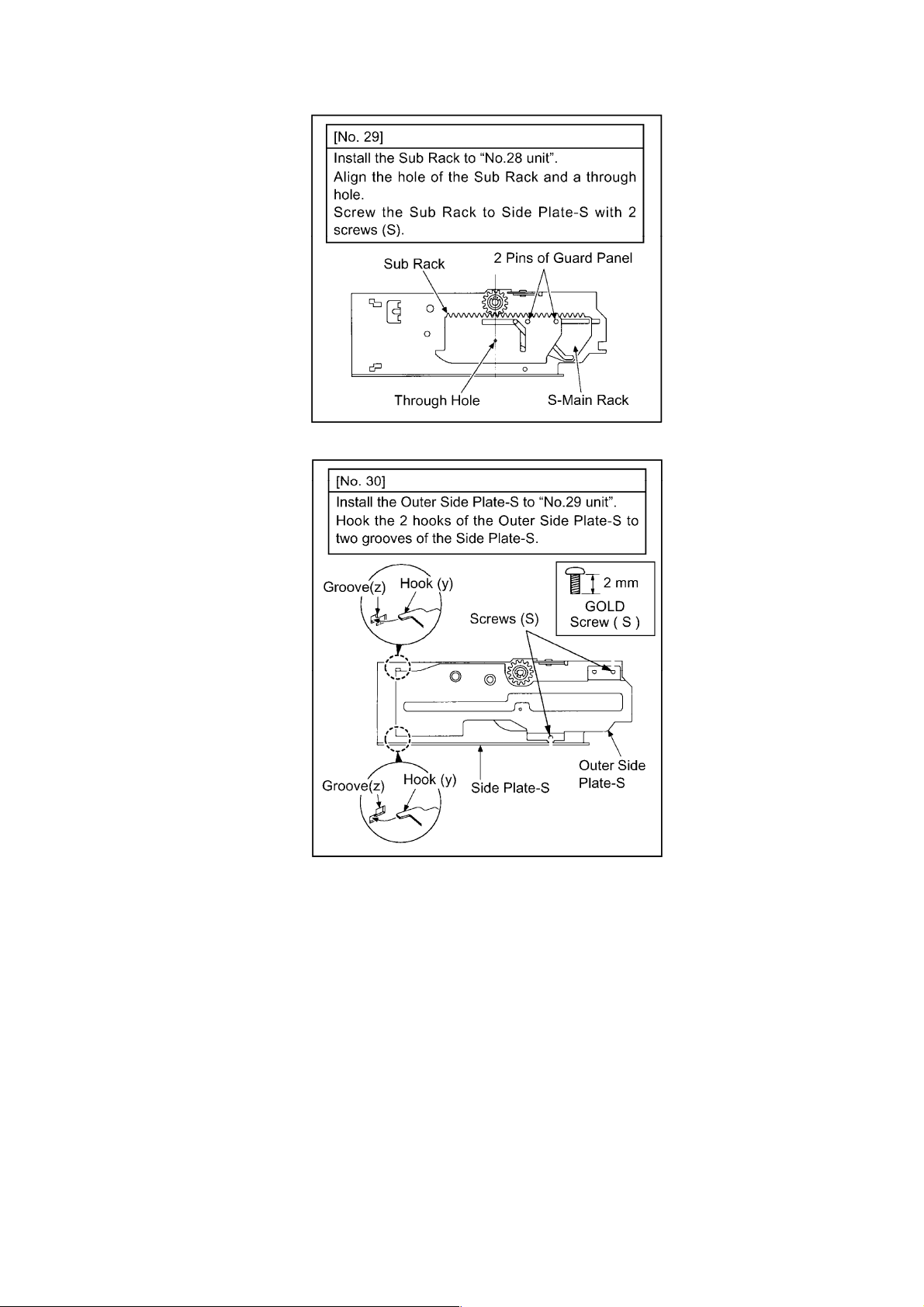
29 "No.28"
unit/SUB
RACK
30 "No.29"
unit/OUTER
SIDE
PLATE-S
Fig. D20
Fig. D21
Fig. D22 4-Pins
Fig. D23 1-Pin
Fig. D24 4-Pins
Fig. D25 2-Hook (w)
Fig.
D26
Fig.
D27
Fig. D28
Fig. D29
Fig. D30 2-Hook (y)
Hook (t)
Upper groove
Lower groove
1-Hole
Upper groove
Lower groove
-----------------------------------------Hook (u)
Groove (v)
2-Groove (x)
-----------------------------------------2-Screws (R)
Gear Phase Alignment
Gear Phase Alignment
2-Groove (z)
-----------------------------------------2-Screws (S)
Page 24
http://cxema.ru
No. ITEM/PART FIGURE REMARKS
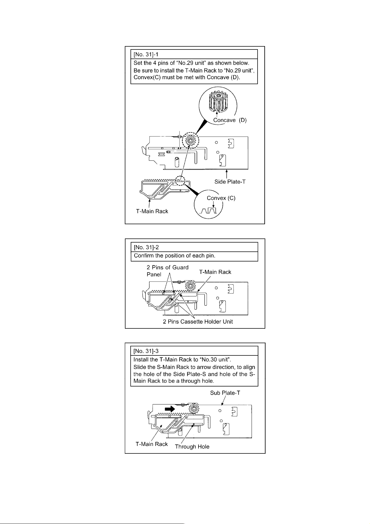
31 "No.30"
unit/T-MAIN
RACK
32 "No.31"
unit/SUB
RACK
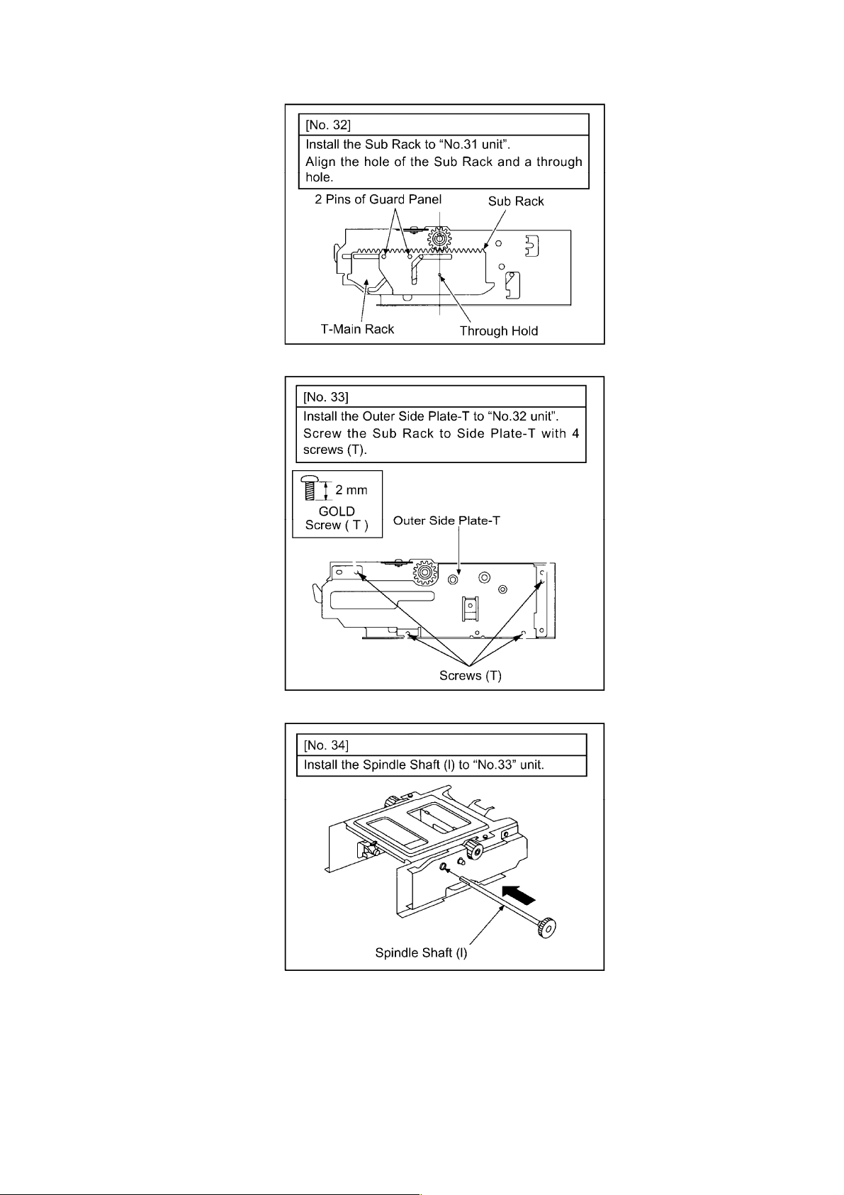
33 "No.32"
unit/OUTER
SIDE PLATE-T
34 "No.33"
unit/SPINDLE
SHAFT (I)
35 "No.34"
unit/SYNCHRO-GEAR
36 "No.35"
unit/INTERMEDIATE
GEAR
37 "No.36"
unit/GUARD
BLOCK
38 "No.37"
unit/MOTOR
ANGLE/WORM
WHEEL
Fig.
D31
Fig.
D32
Fig. D33
Fig. D34
Fig. D35
Fig. D36
Fig. D37 1-Hook (a1)
Fig. D38 2-Cut washer (a3)
Fig. D39
Fig. D40
Gear Phase Alignment
Gear Phase Alignment
4-Screws (T)
1-Groove(a2)
Gear Phase Alignment
4-Screws (U)
Fig. D20
Fig. D21
Page 25
http://cxema.ru
Fig. D22
Fig. D23
Fig. D24
Page 26
http://cxema.ru
Fig. D25
Fig. D26
Page 27
http://cxema.ru
Fig. D27
Fig. D28
Fig. D29
Page 28
http://cxema.ru
Fig. D30
Fig. D31
Page 29
http://cxema.ru
Fig. D32
Fig. D33
Fig. D34
Page 30
http://cxema.ru
Fig. D35
Fig. D36
Fig. D37
Page 31

http://cxema.ru
Fig. D38
Page 32

http://cxema.ru
Fig. D39
Fig. D40
3.2. MECHANICAL ADJUSTMENT
Adjustment procedures, Disassembly Procedures and Assembly Procedures for Mechanism Chassis are
separated volume from this Service Manual.
Please Refer to the Service Manual for DJ-Mechanism Chassis.(VMD9706005A8)
3.3. ELECTRICAL ADJUSTMENT
As for this model, PC-EVR(Tatsujin) system is adopted for all Electrical Adjustments.
In achieving each adjustment, consult description in PC-EVR software for this model.
(All adjustments data is stored in IC2004 (EEPROM)).
Adjustment items are listed in the following table.
Page 33

http://cxema.ru
Circuit/Section Adjustment item Major Relative Components
ADJUST
MENT
OTHERS All Ave/Fix data Saving IC2004(EEPROM)
AV REC/PB RF EQ/ VITERBI Adjustment
REC/PB PG Shifter Adjustment
VIDEO REC/PB Video VCO Adjustment IC2004(EEPROM)
REC/PB E-E Y Level Adjustment 1 IC2004(EEPROM)
REC/PB E-E Y Level Adjustment 2 IC2004(EEPROM)
REC Video-In (Y Level) Adjustment IC2004(EEPROM)
REC Video-In (C Level) Adjustment IC2004(EEPROM)
PB Playback Y Level Adjustment IC2004(EEPROM)
PB Playback C Level Adjustment IC2004(EEPROM)
REC/PB Horizontal Screen Position
Adjustment
AUDIO Audio Level Meter Adjustment IC2004(EEPROM)
SYSTEM CONTROL Tape End/Beg. Sensor
Adjustment
All Ave/Fix data Overwriting IC2004(EEPROM)
Unit Unique ID Writing IC2004(EEPROM)
Function check -----
IC2004(EEPROM)
DD Cylinder, Capstan
Motor,Components on the Tape
Transportation
IC2004(EEPROM)
DD-CYLINER, Components on the
Tape Transportation
IC2004(EEPROM)
IC2004(EEPROM)
Fig. E1 Electrical Adjustment item list
3.3.1. How To Connect The PC-EVR.
Refer to the following figure to connect the VCR unit (NV-DV2000) and PC (Personnel Computer).
Before starting adjustment , confirm that all of the switch set to Normal Position.
No. Part No. Part Name Qty
1 VFK1317 30 Pin Flat card 2
2 VFK1395 232C(M3) I/F Cable 1
3 VFK1409 Measuring Board 1
4 VFK1410 EVR Connection Board 1
Fig. E2 Cable list for PC-EVR Adjustment
3.3.2. Measuring Equipment
1. OSCILLOSCOPE
(0.005-5V/Div. DC-More than 60MHz)
2. FREQUENCY COUNTER
(0 - 50MHz)
Fig. E3 Necessary connection for PC& the unit
Page 34

http://cxema.ru
3.4. SERVICING FIXTURES& TOOLS
Page 35

http://cxema.ru
4. ABBREVIATIONS
Page 36

http://cxema.ru
Page 37

http://cxema.ru
Page 38

http://cxema.ru
Page 39

http://cxema.ru
Page 40

http://cxema.ru
5. INPUT/OUTPUT CHART
5.1. INPUT/OUTPUT CHART FOR IC7501 [Timer Microprocessor]
Page 41

http://cxema.ru
Page 42

http://cxema.ru
5.2. INPUT/OUTPUT CHART FOR IC6001 [SYSCON/SERVO
Microprocessor]
Page 43

http://cxema.ru
Page 44

http://cxema.ru
Page 45

http://cxema.ru
5.3. INPUT/OUTPUT CHART FOR IC2001 [LSI Microprocessor]
Page 46

http://cxema.ru
Page 47

http://cxema.ru
Page 48

http://cxema.ru
Page 49

For your safety please read the following text carefully
This appliance is supplied with a moulded three pin mains plug
for your safety and convenience.
A 5 amp fuse is fitted in this plug.
Should the fuse need to be replaced please ensure that the
replacement fuse has a rating of 5 amps and that it is approved
by ASTA or BSI to BS 1362.
Check for the ASTA mark or the BSI mark on the body of
the fuse.
How to replace the Fuse
¡There are two types of the AC Mains Lead assembly:
A and B as shown below.
1Open the fuse compartment with a screwdriver.
2Replace the fuse and fuse cover.
TYPE A
If the plug contains a removable fuse cover you must ensure
that it is refitted when the fuse is replaced.
If you lose the fuse cover the plug must not be used until a
replacement cover is obtained.
A replacement fuse cover can be purchased from your local
Panasonic Dealer.
IF THE FITTED MOULDED PLUG IS UNSUITABLE
FOR THE SOCKET OUTLET IN YOUR HOME THEN
THE FUSE SHOULD BE REMOVED AND THE PLUG
CUT OFF AND DISPOSED OF SAFELY.
THERE IS A DANGER OF SEVERE ELECTRICAL
SHOCK IF THE CUT OFF PLUG IS INSERTED INTO
ANY 13 AMP SOCKET.
If a new plug is to be fitted please observe the wiring code as
shown below.
If in any doubt please consult a qualified electrician.
IMPORTANT
The wires in this mains lead are coloured in accordance with
the following code:
Blue: Neutral
Brown: Live
As the colours of the wires in the mains lead of this appliance
may not correspond with the coloured markings identifying the
terminals in your plug, proceed as follows:
The wire which is coloured BLUE must be connected to the
terminal in the plug which is marked with the letter N or
coloured BLACK.
12
TYPE B
12
The wire which is coloured BROWN must be connected to the
terminal in the plug which is marked with the letter L or coloured
RED.
Under no circumstance should either of these wires be
connected to the earth terminal of the three pin plug, marked
with the letter E or the Earth Symbol .
Page 50

[ REF NO. 30000 SERIES ]
VIDEO MAIN SIGNAL PATH IN PLAYBACK MODE
R18
Q2
R2
L2
C3
68u
18P
E
R1
820
R19
1K
4.8
1.4
2.1
1.4
D
C
B
0
Q5
2SB1218(AMP)
R29
1K
R301KL13
2.1
1.5
0
Q9
2SB1218 (AMP)
PS2
C SYNC
V PULSE
IIC DATA
IIC CLK
H BLK
GND (D)
DNR C OUT
GND (D)
DNR Y OUT
GND (D)
DNR C IN
GND (D)
DNR Y IN
YC REG 5V
HSS
V BLK
TO VIDEO SECTION
IN MAIN PP3502
( D-1 )
PS1
GND
COMB OFF (L)
YC REG 5V
C SEP OUT
GND
Y SEP OUT
I/O -5V
FSC
I/O 5V
GND
CPN C IN
CPN (L)
CPN Y IN
GND
CPS V IN
TO VIDEO SECTION
IN MAIN PP3501
( C-1 )
R21
220
C4
68P
1
2
3
4
5
6
7
8
9
10
11
12
13
14
15
16
1
2
3
4
5
6
7
8
9
10
11
12
13
14
15
Q6
2SB1218
(AMP)
4.1
R20
100
C21
100PL95.6u
33u
C27
22P
LB4
LB5
LB6
L3
18u
L14
33u
C28
56P
LB4~6
VLP323A601T
A
1K
R3
1K
2.3
0
Q1
2SB1218(AMP)
R22
560
R24
33K
4.2
1.8
1.1
R23
240
R31
1K
C29
6V22
C30
22P
(A1)
(A2)
IC1
(A3)
MC14053BF
(A4)
(C/Y INPUT SELECT)
(A5)
(A6)
(A7)
(A8)
(A9)
(A10)
(A11)
(A12)
(A13)
2SB1218
(BUFFER)
R7
R5
33K
560
4.8
4.2
Q3
1.6
1.6
Q7
2SC3930
(BUFFER)
C22
6V22
R25
22K
R32
33K
R33
27K
0
VSS VEE INH
4.4 4.1 4.1 2.2 2.1 2.1 2.3 5.0
2SC3930
(AMP)
4.2
R4
180
1.1
R6
270
R26
C23
1100
22P
R35
560
2.0
L15
10u
C31
82P
R34
560
C2
0.1
-5.2
<0.2>
CBA
L10
33u
C5 0.1
1.8
4.1
1.3
R37
120
L
LH
R9
R8
1100
22K
L11
33u
C24
56P
4.8
4.1
2.3
Q10
2SC3930
(AMP)
R36
100
4 3 2 1
C
H
Y C VDD
1351261171089 14 15 16
L1
VLQ0319K330
C6
39P
L4
33u
Q8
2SC3930
(AMP)
R27
1k
L12
33u
C25
C26
56P
22P
Q11
2SB1218
(BUFFER)
2.3
Q12
2SB1218
(AMP)
2.300000
L
B
C7
33P
Q4
2SC3930
(AMP)
L5
39u
4.8
2.1
<2.6>
R38
1K
3.0
0
H
C1
0.1
4.8
2.0
<3.0>
2.8
<3.7>
R10
1K
R11
820
2.8<3.3>
R28
820
L17
VLP0319K
330
R44
5600
8 7
+V
1 2 3 41 2 3 4
4.5 0 0
R46
R51
100K
0
(A2) (A11) (A12)(A5)
VIDEO MAIN SIGNAL PATH IN REC MODE
C10
C8
6V100
C9
0.1
28 27 26 2552462372282192010191118121713161415
1 2 3 41234
3.3 0 0 0 0
TL1
L6
VLQ0319K
330
R45
22K
C38
1000P
X2
VSX1110
IC3
NJM2903M
(AMP)
65
2.9
R47
2700
D1
MA8027H
C32 0.01
R43
0
R95
470
0004.9
-V
C12
8200
2.8
<3.3>
VSS4
VDD4
VREF1
IC2
TC9090AF (3D IC INTERFACE)
VREFH
VSS1
ADIN
1.4
(1.5)
<1.9>
C33 50V0.47
C86
150P
R96
1M
C87
15P
C41
0.1
R48
390
C39
C40
0.1
6V47
0.01
R13
12K
C11 0.01
Y OUT
VDD1
1.44.8 4.8
C34 0.1
C35 16V10
L16
VLQ0319K
330
BIAS2
VREFL
D3
HVU17
R14 10K
C12 0.01
2.82.8
BIAS3
C OUT
BIASI
P/S
R39
C37 0.01
C36 0.01
47K
R97
100K
R98
33K
TL2
C89
0.1
C92
C93
0.1
0.1
C88
0.1
C100
0.1
16 15 14 1351261171089
VDD
IC4
TCHC4538AFEL (V PULSE MONO MULTI)
A
1 2 3 4
0 000 0
4.9 4.9 4.9
C43
470P
VR3
EVM7JSX30B54
H BLK
R15 10K
C13 0.01
C14 180P
1/2VDD
SDA
(TVSW1)
4.4 4.41.2
R40
3300
C90
470P
R63
0
B
R16 820
VFIL
SCL
(TVSW2)
C94
0.1
C16 120P
0
C15
0.01
C17
16V10
C18
0.1
00 0
CK IN
VDD2
RESET
(TVSW3)
TEST1
(VENH0)
00
QR1
UN5213
4.4
(COMP OFF L :OFF)
IC7
PST9142NR
(RESET)
R100
100K
4.94.94.9
L7
VLQ319K330L8VLQ319K330
C19
16V10
C20
0.1
4.84.84.8 2.32.33.4 1.91.6
VSS2
VSS3
VDD3
TEST2
(VENH1)
KILLER
PLLSEL
00.4
R42
0
R41
0
R17
0
000
3 2 1
SUB NC
GND
OUT
4.8 4.9
4 5
R101
150K
R99 1K
3
4.8
R109
0
IN
D2
MA142K
0000
VSS
LB2
VLP321A
300T
C57
6V22
R65
22K
1
2
R93
3300
R50
22K
R54
0
(A13)
(A6)
(A7) (A1) (A4)(A3)
LB7
VLP0321
A300T
C106
1u
(A8) (A15) (A16)
(A9) (A10) (A14)
C107
1u
C62
0.01
R64
33K
1.8
R66
560
4.2
1.1
R68
270
R74
33K
R75
22K
C63
0.1
LB1
VLP0321A300T
C84
0.1
C81 0.1
C82 0.1
C83 0.1
C97
6V100
Q15
2SB1218
(AMP)
4.2
Q14
2SC3930
(BUFFER)
R67
270
(2.0)
<1.7>
Q18
2SC3930
(BUFFER)
R55 0
C77 0.1
C78 0.1
C79 0.1
C80 0.1
R94
3300
C99
0.1
Q16
2SB1218
(AMP)
R76
560
1.8
R77
270
C56
6V47
C73
0.1
4.9
2.0
4.2
(0)
1.1
(2.6)
1.5(2.3)
1.5(2.3)
C85
0.1
C76
0.1
4.8
2.4
C61
50V1
C69
R80
10K
4.3
(2.3)
<2.5>
28 27 26 25 24 23 22 21 20 19 18 17 16 15
VDD
DIN4
1 2 3 4 5 6 7 8 9 10 11 12 13 14
0
0.1
(1.7)
<0>
(B11)
000000000
ADT2
ADT1
PST0
PST1
0.1
(B10) (B9) (B8) (B7)
2.6
2.5
(0)
2.9
(3.0)
<1.7>
<1.8>
<1.6>
DIN3
DIN2
DIN1
DIN5
DIN6
DIN7
0.1
0.1
00
(2.9)
(2.0)
<0>
<0>
(B12) (B13) (B14) (B1) (B2) (B18) (B17) (B16) (B15)
TL3
4.8
3.5(3.0)<3.2>
PWM
ADT0
RET0
POT7
D GND
PST2
PST3
PST4
PST5
PST6
L20
27u
C58
12P
R81
1K
R82
1K
2.5
0
4.9
0.9(1.3)<1.1>
1.1(2.3)<2.3>
VCXOVDD
A GND DA
0
1.6
2.2(3.1)
C98 0.1
R72
8200
R71
1K
C59
27P C60
Q21
2SD1819
(AMP)
R83
3300
C45
8P
L18
27u
C44
12P
IC8
MSM518221
(MEMORY)
C101
0.1
C91 0.01
4.9
0.8(1.2)
FS
DVDD
VCXOCK
(28) INV OUT
(29) INV IN
(30) VCXO GND
(51) C OUT
(52) AVDDDA
(53) VB1Y
Y OUT
AVSS
AVDD
000
4.8
R102 1K
R110
0
6V47
ADT7
D GND
BLNK
R103 1K
3.1
C46
12P
ADT6
PVPH
0
R111 0
Q17
2SD1819
(AMP)
4.8
2.5
ADT5
MOD0
MOD1
4.9
4.9
3.0
R79
10K
C64
0.01
R86
1K
C95
6V100
ADT4
IC6
TC90A11F
(3D Y/C SEP)
MOD2
R73
1K
(1.8)
ADT3
D GND
000000000
R69
1K
R70
820
2.6
2.0
0
4.9
4.2
Q19
2SB
1.9
1218
(AMP)
R78
1.9
270
Q20
2SB1218
(AMP)
0
2.3
30
4.8
4.8
3.4
1.4
1.3
4.9
1.4
2.4
3.4
3.3
1.6
2.4
29282726252423222120191817161514131211
VDD
31323334353637383940414244454647484950
0
VSS
0
LPH
0
FSC
0
AVSS
AVDD
CLAMP
0
A GND AD
V REF HY
A INY
V REF LY
BIAS
A VDD AD
43
V REF LC
A INC
V REF HC
0
A GND AD
VB2
VB1C
V REF
5152535455565758596061626364656667686970717273747576777879
3.5
4.9
LB3
VLP0321A300T
R84
1200
Q22
2SB1218
(2.5)
(AMP)
1.9
1.3
(1.8)
0
R88
1200
Q23
2SB1218
(AMP)
2.6
2.0
0
LB8
VLP0321A300T
(B19)
1.2
(1.1)
4.94.94.9
<0.9>
IE
NC
WE
DIN0
RSTW
SWCKNCREOEDOUT7
4.9
TL4
TL5
TL6
TL7
TL8
TL9
TL10
POT4
POT3
C SYNC
KILL
0
4.5
0(0.3)
R105 100
R106 100
R107 100
POT2
POT1
(1) WCK
(2) RSTW
(3) DVDD
(78) DVDD
(79) ATH
(80) RSTR
IICK
IIDT
4.2
R108 100
000000000
POT0
ACK
0
TL11
987654321
10
POT6
POT5
PST7
DOP
4.8
R104 10K
C67
R85
8P
1800
R90
4300
C71
R89
15P
10K
(B20) (B3) (B4) (B5) (B6)
2.9
1.4
2.0
(2.5)
(1.7)
(2.3)
00
<1.8>
<1.9>
<1.8>
RSTR
SRCK
DOUT0
DOUT1
DOUT6
0
1.3(1.1)<1.0>
D GND
FSC4
DVDD
0
TL13
MO0
MO1
MO2
MO3
MO4
MO5
MO6
MO7
RCK
0
DOUT5
1.9(2.3)<2.0>
MI0
1.8
MI1
2.2(2.5)<1.9>
MI2
3.3(1.6)<2.9>
MI3
2.5(2.8)<2.2>
2.4(2.8)<2.2>
3.1<2.6>
2.0(2.3)<3.9>
0
0
4.9
0.1(1.9)<0.4>
0.1(1.5)<0.4>
0.1(2.9)<0.4>
0.1(2.0)<0.4>
0(1.5)<0.1>
MI4
0(1.0)<0.1>
MI5
0(2.7)<0.1>
MI6
0(1.5)<0.1>
MI7
1.0
81 82 83 84 85 86 87 88 89 90 91 92 93 94 95 96 97 98 99 10 0
80
0
(1.3)0(2.6)0(1.1)0(1.3)
4.9
4.9
L21
47u
C70
3P
L22
47u
3.3
(1.5)
<1.5>
DOUT2
DOUT4
TL12
R87
1200
C68
3P
R91
1K
C72
8P
DOUT3
VSS
01.1 4.9
(B1)
(B2)
(B3)
(B4)
(B5)
(B6)
(B7)
(B8)
(B9)
(B10)
C96
0.1
(B11)
(B12)
(B13)
(B14)
(B15)
(B16)
(B17)
(B18)
(B19)
(B20)
(A16)
(A15) (A14)
NOTE: THE MEASURMENT MODE OF THE DC VOLTAGE OUT OF THE BRACKETS ON THIS DIAGRAM IS STOP MODE
WITH PAL COLOUR SIGNAL. (MINI DV:SP MODE) ·LINE IN SIGNAL LEVEL... -6dB 400Hz
THE MEASURMENT MODE OF THE DC VOLTAGE IN THE BRACKETS ( ) ON THIS DIAGRAM IS PLAYBACK MODE
WITH PAL COLOUR SIGNAL. (MINI DV:SP MODE) ·LINE IN SIGNAL LEVEL... -6dB 400Hz
THE MEASURMENT MODE OF THE DC VOLTAGE IN THE BRACKETS < > ON THIS DIAGRAM IS RECORD MODE
WITH PAL COLOUR SIGNAL. (MINI DV:SP MODE) ·LINE IN SIGNAL LEVEL... -6dB 400Hz
1
24
3
5
6789
NOTE : DO NOT USE ANY PARTS NUMBER SHOWN ON THIS SCHEMATIC
DIAGRAM FOR ORDERING.
WHEN YOU ORDER A PART, PLEASE REFER TO PARTS LIST.
Page 51

AUDIO MAIN SIGNAL PATH IN PLAYBACK MODE
AUDIO MAIN SIGNAL PATH IN REC MODE
(A1)
R4335
22K
E
V
A IN (L)
V
A IN (R)
V
SS ON (H)
C4311
0.1
04.9 0 0
16 15 14 13
8 7 6 5
1 2 3 4
1
2 3 4
000
R4315
12K
C4379
33P
C4317
12K
D
IF
D REG 5V
V
IF
GND (D)
IF
A REG 5V
V
AUDIO DATA
V
AUDIO CLOCK
V
AUDIO ST1
IF
PCM OUT (L)
V
AUDIO ST2
IF
PCM IN (R)
IF
PCM IN (L)
V
EE MON (H)
IF
MIX VV (L)
IF
METER (L)
IF
METER (R)
IF
LINE OUT (R)
IFVV
C
V
V
IF
IF
IF
IF
LINE OUT (L)
LCH (H)
RCH (H)
LCH (L)
RCH (R)
PCM OUT (R)
GND (A)
(A1)
(A2)
(A3)
(A4)
(A5)
(A6)
(A7)
(A8)
(A9)
(A10)
(A11)
(A12)
(A13)
(A14)
(A15)
(A16)
R4390
10K
R4305
10K
R4307
18K
C4371
33P
04.9 0 0
16 15 14 13
8 7 6 5
1 2 3 4
1 2 3 4
000
R4316
10K
R4319
100K
R4306
18K
C4378
33P
R4320
10K
R4321
100K
IC4305
NJM4558M
-5.0
C4319
0.1
C4309
33P
IC4302
NJM4558M
-5.0
C4372
0.1
C4304
0.1
C4335
50V2.2
C4325
50V2.2
R4328 200K
C4323
16V10
IC4308
M62409FP
R4325
200K
R4322
200K
C4316
16V10
IC4306
M62409FP
R4318
200K
C4324
0.068
32 31 30 29 28 27 26 25 24 23 22 21 20 19 18 17
VCC1
1/2VCC
AGND
1/2VCC
OUT
12345678910111213141516
0 3.9 0 03.9 3.9 3.9 3.9 3.9 3.9 3.9 3.9 7.9 0 4.9 4.9
C4327
6V47
32 31 30 29 28 27 26 25 24 23 22 21 20 19 18 17
VCC1
1/2VCC
AGND
1/2VCC
OUT
12345678910111213141516
0 3.9 0 03.9 3.9 3.9 3.9 3.9 3.9 3.9 3.9 7.9 0 4.9 4.9
C4320
6V47
TIM2
TIM1
TIM2
TIM1
C4331
0.068
C4322
0.068
ZERO2
ZERO1
ZERO2
ZERO1
LB2
LB1
C4318
0.068
LB2
LB1
C4340
C4343
50V2.2
16V10
HB2
HB1
C4341
C4336
50V2.2
C4329
50V2.2
C4330
50V2.2
C4344
16V10
C4332
16V10
C4333
16V10
50V2.2
HB2
HB1
C4326
50V2.2
C4348
16V10
5.000000 3.93.93.93.93.93.93.93.93.9 7.9
A0
A1
DGND
VCCSTCLOCK
C4350
16V10
C4337
16V10
5.005.0000 3.93.93.93.93.93.93.93.93.9 7.9
A0
A1
DGND
VCCSTCLOCK
C4334
0.1
C4349
0.1
VDO
DATA
C4339
0.1
VDO
DATA
C4351
0.1
C4346
0.1
C4342
16V10
(A3) (A6) (A7) (A8)(A5)
(A2)
R4312 100
R4310 100
R4308 100
(A4)
R4396 100
R4336
10K
C4353
0.1
R4347
R4345
22K
10K
C4345
0.1
R4343
22K
R4402
5600
16 15 14 13 12 11 10 9
VDD X2 X1 X X0 X3 A B
Y0 Y2 Y Y3 Y1 INH VEE VSS
1 2 3 4
000000 0
R4401
5600
R4332
22K
004.9 0000 0
5 6 7 8
-5.0
3.1
0
0
QR4303
UN5213(MIX VV L :OFF)
IC4310
NJM4558M
R4354
22K
R4405
5600
R4403
5600
Q4315
0
2SD1819
(SS H :ON)
00
C4355
0.1
IC4309
MC14052BF
C4384
0.039
IC4311
NJM4558M
8 7 6 5
1
000
R4351
3900
C4381
33P
0
Q4314
2SD1819
0
(SS H :ON)
0
C4356
0.1
0 0 0 -5.0
R4357
36K
C4374
33P
C4406
5600
R4353
3900
C4380
33P
04.9 0 0
2 3 4
-5.0
C4352
10K
C4385
0.039
R4360
R4373
33P
04.9 0 0
8 7 6 5
1 2 3 4
R4359
10K
36K
R4356
10K
R4407
5600
R4367
10K
C4360
C4358
0.1
0.1
(A9)
(A11)
(A10) (A12)
R4359
0.1
IC4313
MC14052BF
C4362
0.1
R4388
10K
R4373
51K
5 6 7 8
R4355
22K
R4323
47K
R4324
47K
5 6 7 8
004.9 0000 0
-5.0
C4364
0.1
-5.0
16 15 14 13 12 11 10 9
VDD X2
X1 X X0X3A B
Y0 Y2 Y Y3 Y1 INH VEE VSS
1 2 3 4
000000 0
R4369
51K
04.9 4.94.90000
16 15 14 13 12 11 10 9
VDD X2 X1 X X0 X3 A B
Y0 Y2 Y Y3 Y1 INH VEE VSS
1 2 3 4
000000 0
(A13) (A15) (A16)
(A14)
4.9
QR4304
UN5213
(R CH L :OFF)
0
4.9
QR4305
UN5213
(L CH L :OFF)
IC4314
MC14052BF
C4368
0.1
0
0
0
R4385
100
R4381
100
05.0 0 0
-5.0
R4382
0
IC4315
NJM4558M
C4367
0.1
R4374
100
0
0
Q4310
2SD1819
0
R4386
1K
R4389
4700
IF
A MUT (H)
IF
UNREG 6V
IF
-8V
IF
8V
IF
B
REG 12V
IC4316
UPC1093J
2.4 0 8.5
A
: TO POWER SECTION IN MAIN
P
: TO VIDEO SECTION IN MAIN
V
: TO RF I/F SECTION IN MAIN
IF
1
R4397
0
C4321
0.01
IC4303
UPC78L05J
OUT GND IN
4.9 0 7.6
C4308
C4310
0.1
0.1
C4313
R4311
16V10
C4307
6V220
NOTE: THE MEASURMENT MODE OF THE DC VOLTAGE OUT OF THE BRACKETS ON THIS DIAGRAM IS STOP MODE
WITH PAL COLOUR SIGNAL. (MINI DV:SP MODE) ·LINE IN SIGNAL LEVEL... -6dB 400Hz
THE MEASURMENT MODE OF THE DC VOLTAGE IN THE BRACKETS ( ) ON THIS DIAGRAM IS PLAYBACK MODE
WITH PAL COLOUR SIGNAL. (MINI DV:SP MODE) ·LINE IN SIGNAL LEVEL... -6dB 400Hz
THE MEASURMENT MODE OF THE DC VOLTAGE IN THE BRACKETS < > ON THIS DIAGRAM IS RECORD MODE
WITH PAL COLOUR SIGNAL. (MINI DV:SP MODE) ·LINE IN SIGNAL LEVEL... -6dB 400Hz
1K
R4302
390
R4303
4700
Q4301
2SD1468
(REG)
8.5
R4301
10K
C4302
10V100
12.0
7.9
C4303
0.01
3
R4398
1K
ACR
24
C4306
0.1
IC4301
NJM79L05A
GND IN OUT
231 231
0 -7.5 -5.0
C4305
6V220
C4314
R43141KC4317
33P
C4313
18K
07.6 0 0
8 7 6 5
1 2 3 4
000
R4309
18K
C4312
33P
-7.5
5
16V10
IC4304
NJM4558M
C4315
0.1
C4352
16V100
R4348
680
D4302
MA153
3
21
QR4301
UN5119
(MUTE)
5.7 0
C4354
50V1
R4349
680
R4350
120K
5.7
5.7
0
0
QR4302
UN5212
(MUTE)
R4372
220
R4370
220
0
0
6789
R4366
10K
05.0 0
8 7 6 5
1 2 3 4
000
R4363
10K
R4364
10K
Q4305
2SD1819
0
R4368
1K
C4365
16V10
0
0
0
-5.0
C4361
0.1
Q4306
2SD1819
0
R4371
1K
IC4312
NJM4558M
C4366
16V10
0
0
R4377
10K
C4357
0.1
Q4307
2SD1819
0
R4375
1K
0
0
C4363
0.1
R4379
100
Q4308
2SD1819
0
R4387
4700
R4380
1K
8 7 6 5
1 2 3 4
000
R4376
0
Q4309
0
2SD1819
0
0
R4384
1K
(MUTE) (MUTE) (MUTE) (MUTE) (MUTE) (MUTE)
NOTE : DO NOT USE ANY PARTS NUMBER SHOWN ON THIS SCHEMATIC
DIAGRAM FOR ORDERING.
WHEN YOU ORDER A PART, PLEASE REFER TO PARTS LIST.
Page 52

IC6001
(SYSCON SERVO MICON)
CAPSTAN
UNIT
T -PHOT O Tr .
SOLENOID
LOADING MOTOR
MIC & S-TAB SW
[ BOTTOM SIDE VIEW ]
S1501
S1502
(CASSETTE DOWN)
(SAFETY TAB)
M
HEAD AMP
T-REEL
SENSOR
S-REEL SENSOR
P1502
3
P1502
1
P6001
3
P6001
1
FP6003
2
FP6003
7
FP6003
FP6003
30
FP6003
12
FP6003
25,26
FP6003
27,28
PHOTO LED
20
MODE
SW
(LOADING MOTOR DRIVE)
1
7
LOADING MOTOR
S-PHOTO Tr.
DETECTION SW
IC2501
CONTROL
CIRCUIT
P.OFF(L)
(TO POWER CONTROL CIRCUIT)
2KEY 1
1KEY 2
84KEY 3
P2501
P2501
P2502
FG1
FG2
P2501
3
7
P2501
1
2
5
6
8
9
P2502
22
5
3
1
S4801-4805,
S7503-7514
FG
PG
L (11.2um)
CYL
M
CAP
M
FG
R (11.2um)
19
20
18
QR1001,
QR1006,1007
P7501
8
P7501
7
P7501
9
Q7502,
QR7502
QR7501
YFGIN
YPGIN
YM3
YM1
H1+
CM3
CFG IN
CFG OUT
Q7501,
2
64
15
17
39
30
4
3
IC7501
(TIMER MICON)
59 S.CLK
60 S.DATA OUT
61 S.DATA IN
FP6002
51P.OFF(L)
81S.CLK
82S.DATA OUT
83S .DATA I N
28 OPEN
15CYL.ON(L)
29 CLOSE
30 DOWN
31 S.TAB
Q6001Q6002
4
5
32 SEN.LED
S.PHOTO
T.PHOTO
33 M.LOAD
34 M.UNLOAD
54CYL.FG
92CYL.ET
96DRV CLK
16CAP T.LIM
17CAP R/S/F
93CAP ET
IC3201
(EDA)
HID
57
TSR TSR
56
HIDI
93
97
CYL FG
CYL PG
ATF
DT0
DT15
48
103
120
1
FP6002
4
FP6002
14
FP6002
15
FP6201
40
FP6201
33
FP6201
23
FP6201
22
IC2503
(CYL/CAP DRIVE)
5 YSTB
60 YFG
7 YEC
55 YCLK
46 CTL
49 CRFS
48 CEC
59 YPG
P7902
P7902
P7902
S.REEL
SENSOR
T.REEL
SENSOR
SLOT-IN MOTOR
4
4
IC6002
(MOTOR DRIVE)
P6002
SW+3V
P1501
1
1
P15012P6002
2
FP6003
14
FP6003
15
M
23
1
23
1
24
CONTROL
CIRCUIT
15
IC6003
(T./S. REEL DRIVE)
2
6
6
8
1
7
36 S.LOAD
37 S.UNLOAD
59 T.REEL
60 S.REEL
CPU DATA OUT
73CPU CLK
75CPU DATA IN
74
55CAP FG
64FRP
IC2001
(LSI MICON)
73 CPU CLK
74 CPU DATA OUT
75 CPU DATA IN
IC2502
4
HID
57
DT15
139
154
DT0
IC2504
(FG AMP)
7
2
1
1
6
IC2505
(FG AMP)
2
7
IC3203
(EQ IC)
9
6
IC5001
(H.AMP)
2
57
IC3001
(DV I/O)
58
FRP
P.B.SIGNAL
FROM CYLINDER
Page 53

IC7501
(TIMER u-com)
IC6001
(SYSCON/SERVO u-com)
MAIN DATA / CLOCK TRANSMISSION
IC2001
(LSI u-com)
IC2004
(EEPROM)
SK
2
DO
DI
3
CS
1
4
IC2002
(DAC)
OSD CLK
62
D.OUT
64
S.CLK
S.DATA IN
S.DATA OUT
OSD
OSD CS
ON(H)
73
54
IC3606
(EDIT/OSD u-com)
IC3001
59
60
61
QR6020
81
S.CLK
82
S.DATA OUT
83
S.DATA IN
E.OSD
CLK
77
22
D.OUT
78
23
S.IN24CSCLK
CPU CLK
CPU D.OUT
CPU D.IN
CS
79
E.OSD
ON(L)
80
73
74
75
IC4701
(AY-u-com)
CPU CLK
73
75
CPU D.IN
74
CPU D.OUT
YC
CLK
77
64
YC
CLK
L YC
D.OUT
CYLINDER & CAPSTAN SERVO
YC
SBI
EE.CLK 99
EE.DI
100
EE.DO
103
EE.CS
104
106
DAC LD
69
com CLK
71
com D.IN
com RST
YC
CS
35
38
REM
CS
70
68
com D.OUT
L YC
D.IN
78
79
62
63
YC
SBO
CLK2
DI
1
LD3
IC2005
(com-u-com)
M.SCK
76
80
M.SDO
79
M.SDI
7
RST
DV-IN
A NA.Y-IN
INF
MCVS
REC.
V-Sync
COMPARISON
REFERENCE
COMPARISON
During Editing, Frame Servo is applied for Capstan Servo.
NOTE:
*
P.B.
25Hz
SPEED
ALL MODE
ROM DATACYLINDER REFERENCE
FG
ALL MODECAPSTAN
ROM DATA
FG
IC2001
V-PLL
PHASE
IC3005
VCO
(18MHz)
18MHz
IC3001 IC3003 IC3201
COUNT
DOWN
(25Hz)
FRP
COUNT
DOWN
SSP
(300Hz)
IC3201/IC2001
PHASE
REC/PB CUE/REV
TSR ROM
DATA
HID
PB REC/CUE/
REV/SLOW
ROM DATA
ATF INTERNAL
EFERENCE
FRP (25Hz)
COUNT
DOWN
REC./CUE/
REV/SLOW
IC6001
Over than
X1 tape speed
TSR(150Hz)
Less than
X1 tape speed
HID-3
HID-2
HID-1
AFT
AFT
(TRE)
P.B.
INT.REF.
ROM
ENVE
(Pilot f0-f2)
ROM Data
ROM CYL
FG-Pulse
TSR/ROM
IC3201
HID
GENERATOR
IC6001
ROM Data
ROM
FG-Pulse
ROM Data
ROM
(TRP0-3)
HID-1
(150Hz)
AFT
(TRE)
ENVE
FRP
SPEED
CYL
PHASE
CAP
SPEED
CAP
PHASE
FRAME
SERVO
(Other than Dubbing
(Copying)/Assemble.)
IC2503
CYL-ET
FG-Pulse (Normal P.B.:600Hz)
PG-Pulse (Normal P.B.:150Hz)
ENVE.OUT(TRP0-3/PILOT f0-f2)
CAP-ET
Normal
(Other than left)
EDIT
(Normal P.B.:1,760Hz)
CYL
DRIVE
IC2503
CAP
DRIVE
FG-Pulse
CYLINDER
MOTOR
CAPSTAN
MOTOR
FG1
FG2
(Normal P.B.:880Hz)
FG MIX
IC2502
Page 54

7 8
FRONT
Í / I
¥
DV 2
AV4
IN
S-VIDEO
REAR
NORMAL
DV SELECT
2
VIDEO MAIN SIGNAL PATH IN REC MODE VIDEO MAIN SIGNAL PATH IN PLAYBACK MODE
AUDIO
STEREO
OUT
SERECT
EJECT
<
EDIT 8mm
1
2
VIDEO
L/MONO– AUDIO – R
RECORDER
PLAYER
PRINTER/
D.STILL PICTURE
EDIT CONTROL
PASSIVE
8mm
EDIT
DV
MIXING EDIT
SP/LP TBC 3D DNR PRINT
REW STOP
AUDIO REC LEVEL
010
S-VIDEO
STEREO1 STEREO2
VIDEO
STEREO1
AUDIO MIX
PLAY
100
STILL
ALBUM
INPUT SELECT
L– AUDIO – R
FF PAUSE
¥
REC/OTR
AV4
OUT
CPS-IN
(VIDEO)
IC3903 (VIDEO INPUT SELECT)
AV1-4
IC3002 (Y/C SEPA)
Y/C
SEPA
Y
C
9 10
Y
C
S-VIDEO OUT
AV1(TV
AV2(EXT
)
)
11 1
MONITOR OUT
R AUDIO L
VIDEO S-VIDEO
AV3 IN
6 5
CPN-IN
(S-VIDEO)
AC INT
SECTEUR
T
DIGITAL STILL
¥
DV1
PICTURE OUT
AV1-4Y
AV1-4C
IC3607 (S-VIDEO INPUT SELECT)
4 3
IC3001 (INPUT SEPA)
Y
C
IC3603 (EE/VV SELECT) IC30006 (3D-DNR) IC3601 (SELECTOR)
Y
C
P.B-Y
P.B-C
DV REC PB
PROCESS
DNR
Y
C
IC30008 (2MBF.MEMORY)
MEMORY
REC-Y
REC-C
IC3606 (EDIT/OSD) IC3610 (SELECTOR)
Y
(EDIT/OSD)
C
Y
C
Y
Y/C
C
4
1
2
5
6
8
3
7
9
10
AV3 V OUT
AV 1
NORMAL/
S-VIDEO
AV 2
NORMAL
AV 3 SV OUT
MONITOR OUT
AV 3 V OUT
MONITOR
AV 4 V IN
AV3 SV IN
AV4 SV IN
AV4 SV OUT
AV4 V OUT
AV3 VIDEO IN
JK3906
20
19
15
JK3901
JK3902
20
19
15
S OUT
JK3903
3 4
VIDEO OUT
JK3904
AV4 V IN
JK4851
JK3905
3 4
S IN
JK4852
3 4
S OUT
JK4853
3 4
JK4854
V IN
V OUT (Y.OUT)
C. OUT
V. IN
V. OUT
C
Y
C
Y
C
Y
C
Y
NORMAL
11
S-VIDEO
OUT SW
S3901
S-VIDEO NORMAL
Q3904,3905
Q3902,3903
Q3902 (AV2 OUT)
(H)
15
(L)
IC3901
(AV1 OUT)
(H)
15
(L)
1
2
11
10
9
1
2
11
10
9
IC7501
52 AV2 OUT
IC7501
51 TV (H)
PS3902 PP3402
19 19
PS3902 PP3402
17 13
PS3902 PP3402
13 17
PS3902 PP3402
15 15
P7502 P7901
27 6
PS3901 PP3401
18 18
PS3901 PP3401
16 16
P7502 P7901
29 4
P7502 P7901
31 2
P7501 P7902
21 6
P7501 P7902
20 7
P7501 P7902
23 4
IC3903 (VIDEO IN)
12
13
14
15
SW
AV4 V IN
AV3 S-C IN
AV3 S-Y IN
AV4 S-C IN
AV4 S-Y IN
CPN 2C OUT
CPN 2Y OUT
CPS 2V OUT
10
11
3
9
FRONT (H)
QR6202
QR6203
Q3907
IC3602 (AGC)
PS3901 PP3401
20 20
V IN
9
7
CLAMP
IC6001 45 A2 (L)
IC6001 44 A1 (L)
IC3607 (SELECTOR)
13
12
1
2
3
5
14
15
4
SELA
11
10
B/P (H)
9
C OUT
Y OUT
Y+C OUT
QR6203
IC6001
44 A1 (L)
IC7501
12 B/W (H)
IC3601 (SELECTOR)
3
Q3605
4
5
AV1-PIN 10
15
(H)
1
AV2-PIN 10
2
(L)
Q3606
IC7501 71
(QLINK ON H )
12
13
14
10
B
11
A
9
C
Q3610,3611 Q3617,3620,3622
11
12
14
Q3613,3614
Q3607
Q3623
IC4701
(AY-IN COM)
IIC CLK
IIC DATA
IC3603
(SELECTOR)
5
3
12
13
IC3606
(EDIT OSD CONTROLER)
C IN
2 27
1
Y IN
3 26
V IN
Q3608,3609
7
6
Q3604
4
Q3603
14
Y OUT
C OUT
PP3501 PS30001
PP3501 PS30001
PP3502
PP3502
Q3616,3618
Q3612,3615
15 15
13 13
PP3501
PS30001PP3501
PP3501
PS30002
4
PS30002
3
PP3502
PP3502
PP3502
PP3502
IC30002
Q30009-30012
CPS V IN
IC30001
(C/Y INPUT SELECTOR)
CPN Y IN
Y SEP OUT
6
CPN C IN
1111
C SEP OUT
4
4
3
DNR C IN
10
DNR Y IN
12
DNR Y OUT
8
DNR C OUT
6
IC3610
(IN/OUT SELECTOR)
1 14
3
11
12
Y IN
OSD Y IN
OSD C IN
C IN
CPN C OUT
CPN Y OUT
12 13
14
2
15
3
5
IC30006
(3D DIGITAL NOISE
REDUCTION)
75
IIC CLK
76
IIC DATA
45
A IN C
A IN Y
40
16
Y+C OUT
19
Q30005,30008
1
4
Q30004
100
MI 0
MI 17
82
51
C OUT
Y OUT
35
Q30001
Q30003
(DIGITAL Y/C SEPARA TOR)
3 AD IN
Y OUT
25
C OUT
23
IC30008
(2M BIT FIELD MEMORY)
Q3626
Q3625
Q3627
MEMORY
CPM 2C OUT
CPS 2V OUT
CPM 2Y OUT
Page 55

VIDEO MAIN SIGNAL PATH IN REC MODE VIDEO MAIN SIGNAL PATH IN PLAYBACK MODE
FP3401 FP3201 Y
6 31
FP3401 FP3201
8 29
35
46
Q3002 Q3001
FP3401 FP3201
10 27
FP3401 FP3201
12 25
Q3005,
3006
X3152
IC4201
(OP-AMP)
6PCM IN (R) 7
9 8PCM IN (L)
IC4210
(OP-AMP)
7PCM OUT (R) 6
1 2PCM OUT (L)
IC3004(AV-I/F)
Y
C
IC3004
(AV I/F)
Y
IN
OUT
C
C
IN
OUT
Q3004
IC3153,3154
IC2004
(EEPROM)
IC3001(DVIO) IC3002
Y
Y IN
C IN
Y OUT
C OUT
X IN
X OUT
A/D.
C
CONV
Y
D/A.
C
CONV
CLK 18M1
CLK 18/8M
CLK 18M2
CLK 450K
CLK 18 IN
27MHz
Y/C
MULTIPLEX.
68
DATA
IN/OUT
(8bit)
75
64 21
61
62
63
33
55
STP1
57
SDIO
56
SCLK
AV
I/F
IC3001
(DV I/O)
157
23
165
8
3
8
46
47
2
SK EE CLK
4
DO
3
DI
1
CS
(Shuffling Memory)
DV
TERMINAL
TO/FROM
AUDIO
SECTION
46
44
43
41
80
82
83
85
58
25
3
5
26
27
108
107
81
83
82
99
100
103
104
5Mb
MEMORY
IC4501
(PCM-AUDIO)
IC3002
(SHUFFLE MEMORY)
LBS
DATA
IN/OUT
(8bit)
SOC
SIC
IC3005
(VCO)
CLK 18
IC4501
(AUDIO I/F)
A IN R
A IN L
A OUT L
A OUT R
IC2001
(LSI MICON)
DCS STP2
DC STP1
DCS CLK
DCS DI
DCS DO
EE DI
EE DO
EE CS
LBS
DATA
IN/OUT
(8bit)
ADDRESS
IN
(8bit)
FS CLK
FS SEL 0
FS SEL 1
M CLK
LR CLK
S CLK
SDT 0
SDT 1
ADDRESS
COM CLK
COM DATA OUT
COM DATA IN
46
39
40
15
11
12
14
13
(15bit)
IC3003 (CAS) IC3201 (EDA)
DCT
Shuff.
MEMO.
CTL
IC3701
(DI/F)
35 12
33
32
30
91
93
94
96
97
98
1
9
67
79
154
DATA
139
69
70
71
IC3003
(CAS)
9
7
4
37
ADDRESS
IN
(18bit)
18
SHM225
1
CLK18
16
65
VCOI
68
FS0
67
FS1
79
SDIO
80
SCLK
78
STP2
95
DO MCK
94
DO LRCK
96
DO BCK
86
AI DAT
93
DO DATA
LBS
DATA
IN/OUT
(8bit)
VLC
IC3202
(EDA.M)
50
LBS
DATA
IN/OUT
(4bit)
47
ECC
EDA
MEMORY
(4M)
Desuf.
MEMORY
CTL
24-25
CONV.
151
154
103
120
MODU
VITERBI
(VITERBI-A/D)
IC3201
(EDA)
(REC DATA)
DATA
IN/OUT
(4bit)
ADDRESS
DATA
(15bit)
PB DATA IN
3
CLK 18M
2
CLK 450K
ATF 1
48
IC3202
(ECC MEMORY)
IC2005
(PC I/F)
76
M SCK
79
M SDI
80
M SDO
IC3204
HSE
REC CLK
REF CLK
PB CLK
PB DATA
(41.85M)
LSB
DATA IN
OUT
(15bit)
LSB
ADDRESS
OUT
(9bit)
LSB
ADDRESS
IN/OUT
(9bit)
LSB
DATA IN
IN/OUT
(15bit)
UART I
uART O
IC3203 (EQ)
A/D
CONV.
59
56
74
53
52
62
68
40
25
18
10
18
28
2
10
35
43
50
51
IC5001 (H.AMP)
TO RS-232C
CYLINDER
REC ONLY
PB ONLY
BOTH
IC3202
(EQ)
31 41.85M(REC)
41.85M/72
11
35
33
53 58
36
CLK
9
IC3701
(DIGITAL I/F)
130
DATA IN
(4bit)
133
102
ADDRESS
DATA
(15bit)
120
142
CLK 18M
VCO
LATCH
AGC IN
REF-EQ
LPF
TFIL
HD
ATF
BPF
ATF1
69
TPB-
70
TPB+
71
TPA-
72
TPA+
IC5001
FP3203 FP5002
13 12
62
17
18
59
2
4
5
FP3203 FP5002
16 9
FP3202 FP5002
14 11
7 29
64
57
HSE
AGC OUT
(PB DATA)
ATF OUT
AR 1
OUT
AR 2
OUT
HA 2
HA 1
PB H1
PB H2
MON 2
MON 1
31
36
IN
24
IN
Q5005
28
32
Q5006
34
IN
26
IN
(HR AMP)
RA 1 OUT
RA 2 OUT
Q5003
Q5002
FP5001
5
6
M CYL
7
4
IC3205 (GATE)
2
IC3204
(VITERBI A/D)
7
10
19
LBS
DATA
OUT
(7bit)
11
TO DV
TERMINAL
4
TO EVR
A/D
Page 56

ANALOG Y/C C.B.A.
Transistor
Q30001 B-2 (C)
Q30002 B-2 (C)
Q30003 B-1 (C)
Q30004 D-3 (F)
Q30005 C-3 (F)
Q30006 C-3 (F)
Q30007 B-2 (C)
Q30008 D-3 (F)
Q30009 A-2 (C)
Q30010 A-2 (C)
Q30011 A-2 (C)
Q30012 A-2 (C)
D
C
Q30014 A-4 (C)
Q30015 C-1 (F)
Q30016 C-1 (F)
Q30017 C-2 (F)
Q30018 A-3 (C)
Q30019 A-3 (C)
Q30020 C-2 (F)
Q30021 C-2 (F)
Q30022 C-2 (F)
Q30023 A-3 (C)
Transistor & Resistor
QR30001 B-2 (C)
Integrated Circuit
IC30001 A-2 (C)
IC30002 D-3 (F)
IC30003 A-2 (C)
IC30004 B-2 (C)
IC30006 D-2 (F)
IC30007 B-4 (C)
IC30008 B-3 (C)
(FOIL SIDE)
B
A
Test Land
TL30001 D-3 (F)
TL30002 B-3 (C)
TL30003 B-3 (C)
TL30004 B-3 (C)
TL30005 B-3 (C)
TL30006 B-3 (C)
TL30007 B-3 (C)
TL30008 B-3 (C)
TL30009 D-2 (F)
TL30010 D-2 (F)
TL30011 D-2 (F)
TL30012 D-2 (F)
TL30013 D-2 (F)
Test Point
TP30001 B-2 (C)
TP30004 B-2 (C)
TP30005 A-2 (C)
Adjstment
VR30001 C-3 (F)
VR30003 C-3 (F)
Connector
PS30001 A-2 (C)
PS30002 A-3 (C)
ADDRESS INFORMATION
(C) : COMPONENT SIDE
(F) : FOIL SIDE
(COMPONENT SIDE)
1
2
3
Page 57

Transistor Transistor & Resistor
Q2501 C-3 (F) QR2001 C-2 (F) QR6015 A-7 (C) IC2506 C-3 (F) IC4210 B-6 (C) TL6002 B-7 (C)
Q2502 C-3 (F) QR2002 C-2 (F) QR6016 A-7 (C) IC2507 C-3 (F) IC4501 B-6 (C) TL6003 B-7 (C)
Q2503 A-6 (C) QR2003 B-1 (F) QR6017 A-7 (C) IC2508 A-2 (F) IC6001 B-7 (C) TL6006 B-7 (C)
Q2504 A-6 (C) QR2501 A-6 (C) QR6019 A-7 (C) IC3001 B-4 (F) IC6002 A-2 (F) TL6007 B-7 (C)
Q3001 B-4 (F) QR2502 A-6 (C) QR6020 B-3 (F) IC3002 B-3 (F) IC6003 A-8 (C) TL6009 B-6 (C)
Q3002 B-4 (F) QR3001 C-6 (C) QR6021 A-3 (F) IC3003 B-3 (F) IC6004 A-8 (C) TL6010 B-6 (C)
Q3003 C-4 (F) QR3151 B-3 (F) QR6022 A-2 (F) IC3004 C-6 (C) IC6005 A-8 (C)
Q3004 B-4 (F) QR3152 B-3 (F) QR6023 A-7 (C) IC3005 C-3 (F)
Q3005 B-3 (F) QR3201 B-9 (C) QR6024 A-3 (F) IC3006 C-4 (F) FP3201 C-5 (F)
Q3006 B-4 (F) QR6001 A-2 (F) QR6025 A-3 (F) IC3007 C-4 (F) TL3002 B-7 (C) FP3202 B-5 (F)
Q3007 C-4 (F) QR6002 A-2 (F) IC3008 B-7 (C) TL3004 B-7 (C) FP3203 C-2 (F)
Q3151 B-3 (F) QR6003 A-2 (F) IC3009 C-4 (F) TL3006 B-8 (C) FP6002 A-5 (F)
Q3152 B-3 (F) QR6004 A-1 (F) IC2001 B-2 (F) IC3010 C-4 (F) TL3014 C-7 (C) FP6003 A-9 (C)
Q3201 B-9 (C) QR6005 A-1 (F) IC2002 B-1 (F) IC3011 C-6 (C) TL3020 B-4 (F) P2501 C-3 (F)
Q3202 B-9 (C) QR6006 B-7 (C) IC2003 C-2 (F) IC3012 C-5 (C) TL3024 B-4 (F) P2502 C-3 (F)
Q3203 B-8 (C) QR6007 B-7 (C) IC2004 B-1 (F) IC3153 B-3 (F) TL3026 C-6 (C) P3701 C-1 (F)
Q3204 B-9 (C) QR6008 B-7 (C) IC2005 B-2 (F) IC3154 B-3 (F) TL3027 C-6 (C) P6001 B-9 (C)
Q6001 A-2 (F) QR6009 B-7 (C) IC2006 A-1 (F) IC3201 B-8 (C) TL3028 C-6 (C) P6002 A-7 (C)
Q6002 A-2 (F) QR6010 B-3 (F) IC2501 A-2 (F) IC3202 A-8 (C) TL3201 B-9 (C) PS6001 C-4 (F)
Q6003 A-4 (F) QR6011 A-7 (C) IC2502 C-3 (F) IC3203 B-9 (C) TL3202 B-9 (C)
Q6004 A-3 (F) QR6012 A-3 (F) IC2503 C-7 (C) IC3204 B-8 (C) TL3207 B-8 (C)
QR6013 A-8 (C) IC2504 C-8 (C) IC3205 B-9 (C) TL3208 B-8 (C)
ADDRESS INFORMATION
(C) : COMPONENT SIDE
(F) : FOIL SIDE
QR6014 A-8 (C) IC2505 C-2 (F) IC3701 C-9 (C) TL6001 A-7 (C)
Integrated Circuit
DIGITAL C.B.A.
Connector
Test Land
C
B
A
(FOIL SIDE)
1
24
3
5
6789
(COMPONENT SIDE)
Page 58

123456
JK7651
24
67
13
58
P7651
Page 59

C5029
R5026
R5024
C5030
C5032
C5034
R5021
50
C5028
C5038
C5033
R5028
C5031
C5037
MR4
C5001
R5020
49
64
C5002
R5019
55
60
L5005
1
C5027
C5039
R5003
C5007
C5026
5
R5002
C5040
R5018
C5025
IC5001
C5004
R5004
R5005
R5025
10
Q5003
E
C
C5010
C5024
R5017
CKA7 CKA6
B
L5002
C5023
L5003
3335404548
32
30
25
C5019
C5014
20
17
15
16
MR1
L5007
C5036
R5015
R5014
R5016
Q5006
B
E
C5021
C5020
CKA5
Q5005
B
C5013
C5015
C5035
C
MR2
8
5
1
MR3
CKA2
R5010
CKA1
R5013
R5012
C5016
FP5001
C5018
C5017
C
B
CKA3
CKA4
Q5002
E
C
E
R5029
Page 60

INPUT/OUTPUT C.B.A.
Transistor
Q3901 A-3 TP3002 B-2
Q3902 A-3 TP3021 B-2
Q3903 A-3 TP3030 B-2
Q3904 A-3 TP3031 B-1
Q3905 A-3 TP3032 B-1
Q3907 A-4 TP3901 B-2
Q3908 B-4
Q3909 B-4
Transistor & Resistor
QR3901 A-2 PS3903 A-3
QR3902 B-4
QR3903 C-1
Integrated Circuit
IC3901 B-2
IC3902 A-2
IC3903 A-4
ADDRESS INFORMATION
Test Point
Connector
PS3901 A-2
PS3902 A-3
C
B
(FOIL SIDE)
A
(COMPONENT SIDE)
1
2 4
3
Page 61

MAIN C.B.A.
CAUTION
THE MARK INDICATES THE PRIMARY CIRCUIT TO
DISTINGUISH THE PRIMARY FROM THE SECONDARY CIRCUIT.
PAY ATTENTION NOT TO RECEIVE AN ELECTRIC SHOCK
E
DURING REPAIR AND SERVICE OF THE PRODUCTS.
HOT
D
C
B
(FOIL SIDE)
Transistor
Q1006 B-6
Q1009 C-3
Q1010 A-6
Q1011 A-6
Q3601 D-4
Q3605 D-4
Q3610 C-4
Q3611 C-4
Q3612 D-4
Q3615 D-4
Q3616 D-4
Q3618 D-4
Q3624 C-5
Q4004 C-6
Q4305 B-7
Q4306 B-7
Q4307 B-7
Q4308 B-7
Q4309 B-7
Q4310 B-8
Q4315 B-8
Transistor & Resistor
QR1002 B-6
QR1007 B-3
QR3601 D-4
QR3602 D-4
QR3606 D-6
QR4301 B-8
QR4302 B-8
QR4304 C-7
QR4305 C-7
QR6203 A-7
QR6210 A-5
QR6211 A-5
QR6212 A-5
Integrated Circuit
IC1005 B-3
IC3601 D-4
IC3603 D-3
IC3606 D-5
IC3607 D-5
IC3608 C-4
IC3609 C-5
IC3611 C-5
IC4304 A-7
IC4306 C-7
IC4308 D-7
IC4312 C-8
IC4315 B-7
IC4901 D-3
Test Land
TL7001 A-8
Adjstment
VC3601 C-5
VC3602 D-5
Connector
FP3401 C-7
FP3402 B-7
FP6201 B-7
ADDRESS INFORMATION
A
(FOIL SIDE)
1
24
3
5
678
Page 62

MAIN C.B.A.(COMPONENT SIDE)
IMPORTANT SAFETY NOTICE:
COMPONENTS IDENTIFIED WITH THE MARK HAVE THE SPECIAL CHARACTERISTICS
FOR SAFETY.
WHEN REPLACING ANY OF THESE COMPONENTS USE ONLY THE SAME TYPE.
E
THE MARK INDICATES THE PRIMARY CIRCUIT TO
DISTINGUISH THE PRIMARY FROM THE SECONDARY CIRCUIT.
PAY ATTENTION NOT TO RECEIVE AN ELECTRIC SHOCK
DURING REPAIR AND SERVICE OF THE PRODUCTS.
HOT
R DV
232C
D
C
B
A
CAUTION
Transistor
Q1001 B-3 IC1001 D-5
Q1002 B-3 IC1002 B-3
Q1003 B-3 IC1003 C-5
Q1004 B-5 IC1004 A-4
Q1005 B-5 IC1006 A-3
Q1007 B-5 IC1150 C-7
Q1008 C-5 IC1200 B-8
Q1012 A-3 IC1501 B-3
Q1013 A-2 IC3602 D-2
Q1014 A-4 IC3604 D-2
Q1015 B-3 IC3605 D-3
Q1016 A-4 IC3610 C-3
Q1200 C-8 IC3612 D-4
Q1501 B-2 IC3613 D-3
Q3602 D-2 IC4301 B-1
Q3603 D-5 IC4302 C-1
Q3604 D-5 IC4303 B-2
Q3606 D-4 IC4305 D-1
Q3607 D-2 IC4309 B-1
Q3608 E-1 IC4310 C-2
Q3609 E-1 IC4311 C-1
Q3613 D-4 IC4313 B-2
Q3614 C-4 IC4314 C-1
Q3617 D-4 IC4316 B-1
Q3619 D-4 IC4701 A-5
Q3620 D-4 IC4702 B-5
Q3621 D-5
Q3622 C-4
Q3623 D-3 TL3601 C-4
Q3625 B-3 TL3602 C-4
Q3626 B-4 TL3603 D-4
Q3627 B-4 TL3604 C-4
Q3628 D-3 TL3605 D-5
Q4001 D-2 TL3606 D-4
Q4002 D-2
Q4003 D-2
Q4005 D-3 P1001 D-6
Q4301 B-1 P1101 E-7
Q4314 B-1 P7601 D-6
Q4701 A-5 P7602 D-6
Q4702 A-5 P7901 A-7
Q7601 D-6 P7902 A-1
Q7602 D-6 PP1101 A-7
Transistor & Resistor
QR1001 C-5 PP3402 E-3
QR1003 A-3 PP3403 E-2
QR1004 A-3 PP3501 D-5
QR1005 A-3
QR1006 A-3
QR3603 C-4
QR3604 C-4
QR3605 D-3
QR4001 B-2
QR4303 B-2
QR4701 A-5
QR4702 A-5
QR4703 B-5
QR4704 B-5
QR4705 B-5
QR4706 B-6
QR6202 A-2
QR6204 A-4
QR6205 A-4
QR6206 A-4
QR6207 A-4
QR6208 A-4
QR6209 A-4
ADDRESS INFORMATION
Integrated Circuit
Test Land
Connector
PP3002 D-4
PP3401 E-4
(COMPONENT SIDE)
1
24
3
5
678
Page 63

MT1501
M
Page 64

Page 65

P1502
S1501
123
S1502
Page 66

Precautions for maintenance of timer/main C.B.A.
Disconnection of the flexible cable between P7502 and P7901 for
maintenance or check of the timer/main C.B.A. without applying any voltage
will cause the loss of the back up +B of the timer microcomputer. Be sure to
apply a voltage of +4.5 V to the connector of P7503 before disconnecting the
flexible cable.
If the back up +B is lost, the CH setting and data of the timer will be initialized
D
TIMER C.B.A.
Transistor
Q7501 A-4
Q7502 A-3
Transistor & Resistor
QR7501 A-3
QR7502 A-3
Integrated Circuit
IC7501 B-5
IC7502 B-4
IC7503 B-2
IC7504 D-4
Test Land
TL4801 B-3
TL4802 B-2
TL7501 A-5
TL7502 B-5
TL7503 B-5
TL7505 A-6
TL7506 B-6
TL7509 B-6
TL7510 B-6
Adjstment
VR4801 B-3
VR4802 B-2
Connector
P7501 B-2
P7502 B-7
P7503 B-6
ADDRESS INFORMATION
C
(FOIL SIDE)
Back up battery terminal (1.5 X3)
STILL
B
A
REC
FF
PLAY
STILL
ALBUM
IN SEL
LINE OUT
MIX
STOP
REC
S OUT
REW
PRINT
3 DNR
TBC
SP/LP/ELP
MIX LED
EDIT MODE 2
EDIT MODE 1
AUDIO
OUT
8mm
CONTROL
STEREO
SELECT
LINE IN
EDIT
EJECT
DV F/R SW
POWER
S IN
(COMPONENT SIDE)
1
24
3
5
678
Page 67

VIDEO MAIN SIGNAL PATH IN REC MODE
RHY RSTVI1
E
INTPLD1
ADDT0LD2
ADDT1LD3
ADDT2LD4
ADDT3LD5
ADDT4LD6
ADDT5LD7
ADDT6LD8
ADDT7LD9
ADDT8LD10
ADDT9LD11
ADDT10LD12
ADDT11LD13
ADDT12LD14
ADDT13LD15
ADDT14LD16
DT15LD17
ALELD18
DCLD19
D
C
BCLKLD20
RST DIFLD21
BD0VD1
BD1VD2
BD2VD3
BD3VD4
SMPVD5
CLK18M2VD6
SSPVD7
FRPVD8
INFVD9
TMSVD10
TCKVD11
GNDVD12
VIDEO MAIN SIGNAL PATH IN PLAYBACK MODE
L1
L2
L3
L4
L5
L6
L7
L8
L9
L10
L11
L12
L13
L14
L15
L16
L17
L18
L19
L20
M1
M2
M3
M4
M5
M6
M7
M8
M9
M10
M11
2V 3V
C3701
C3702
C3715
C3716
C3717
GND
ADB4
C3718
0.1
0.1
AD14
AD13
AD12
ADB3
ADB2
VCCADB1
L1
L2
L3
L4
L5
L6
L7
L8
L9
L10
L11
L12
L13
L14
L15
L16
L17
L18
L19
L20
M1
M2
M3
M4
M5
R3721 10K
R3722 10K
R3723 10K
R3724 10K
R3725 10K
M6
M7
R3701
100K
0.1
0.1
0.1
0.1
108 107 106 105 104 103 102 101
AD11
0.1
0.1
2.1
0.1
0.1
0.1
0.1
0.1
0.1
0.1
0.1
0
0
0.7
2.1
3
2.1
1.3
1.3
1.3
1.3
2.1
0
0
0
0
2.1
2.1
1.1
3
0
AD10
109
AD9
110
AD8
111
CC A (2/3)
V
112
AD7
113
AD6
AD5
114
AD4
115
GND
116
AD3
117
AD2
118
AD1
119
AD0
120
GND
121
/LCNTD
122
/RD
123
ALE
124
/DC
125
BCLK
126
V
127
CC B (2/3)
/V
128
CC
129
/VCC B (2/3)
AD15/DBA0
130
AD14/DBA1
131
AD13/DBA2
132
AD12/DBA3
133
ADB11/SMPA
134
GND
135
ADB10/DBB0
136
ADB9/DBB1
137
ADB8/DBB2
138
ADB7/DBB3
139
ADB6/SMPB
140
141
VCC B (2/3)
CLK18
142
V
143
CC
144
SSP
ADB5
GND
1 2 3 4 5 6 7 8 9 10 11 12 13 14 15 16 17 18 19 20 21 22 23 24 25 26 27 28 29 30 31 32 33 34 35 36
AD15
VCC A (2/3)
ADB0
100
CC
V
ADEN
/INTP
BKRDY
NTZIHZ
CYCLEIN
GND
UPPEN
NTOUT
CYCLD
GND
NTCLK
RAMEZ
IC3701
TSB13LV11PBW
(DIGITAL INTERFACE)
CYCLS
CLK25
VCC/RST
LCNA
CC
V
LPWRDN
FRP
VFRP
C3703
1000P
R3703
10K
GND
TEST0
SS
D.V
GND
LPS
C/LKON
TEST1
S1/TEST2SOSCK
C3704
0.1
CNA
C3706
0.1
R3702
0
TESTM1
/RESET
TESTM2
VCC/SEN
FL3704
VLF1466B223T
1
3
2
3V
C3707
1000P
C3705
8191 8292 8393 8494 8595 8696 8797 8898 8999 90
CC
/ISD
A.V
TMS
TCK
0.1
PWRDN
/TRST
1.130.1 0.1 0.1 0.1 0.1 0.1 2.1 3 2.8 1.4 1.330333332.83330
PLL FLT
GND
C3727
DD
PLL V
TDI
0.1
PLL GND
TDO
PLL GND
/LISO
XI
LL REC
0333330.10.11.51.5330000300 3
7374757677787980
R3738
0
X3701
VSX0846
(24.578MHz)
XO
TPA+
TPATPB+
TPB-
CPS
A.VCC
A.V
A.GND
A.GND
TPBIAS
A.GND
A.GND
D.GND
D.V
SYSCLK
CTL1
CTL0
LREQ
PC2
PC1
PC0
D.V
D.GND
GND
V
LSYS CLK
LCTL0
LCTL1
LD0
LD1
LD2
LD3
CC
V
1.9
72
1.9
71
0
70
0
69
0
68
R0
1.2
67
R1
0
66
3
65
3
64
CC
63
62
1.9
61
60
59
58
3
57
CC
1.4
56
0
55
D1
0
54
D0
0
53
0
52
0
51
50
49
48
3
47
CC
46
45
3
44
CC
1.4
43
0
42
0
41
0
40
0
39
0
38
0
37
C3708
R3708
C3709
R3709 2700
R3710 3300
R3711 390K
C3710
1000P
R3739 10K
R3740 10K
3V
6P
1M
6P
R3715
56
R3716
56
R3717
56
R3718
56
1
2
3
4
5
6
R3719
390
P3701
C3713
1
C3714
270P
R3720
4700
TPA+
TPA -
DV GND
TPB+
TPB -
DV GND
TO RF I/F SECTION
IN MAIN
P7601 (D-4)
R3735 0
D REC 2VVI2
B
D REC 2VLD22
TDISD1
D REG 3VVI3
A
SL
: TO DIGITAL (SYSTEM CONTROL & SERVO)
: TO DIGITAL (VIDEO 1)
VD
VI
: TO DIGITAL (VIDEO 2)
LD
: TO DIGITAL (LSI MICON)
DIF TDOVI4
1
24
FL3701
VLF1466B223T
3
2
FL3702
VLF1466B223T
3
2
1
C3719
6V10
1
C3720
6V10
3V
M8
M9
M10
M11
3V
VLF1466B223T
3
R3737 27
FL3703
2
R3733 10K
R3732 10K
R3731 10K
R3730 10K
R3729 10K
R3728 10K
C3723
C3722
0.1
0.1
1
C3721
6V10
NOTE: THE MEASURMENT MODE OF THE DC VOLTAGE OUT OF THE BRACKETS ON THIS DIAGRAM IS STOP MODE
WITH PAL COLOUR SIGNAL. (MINI DV:SP MODE) ·LINE IN SIGNAL LEVEL... -6dB 400Hz
THE MEASURMENT MODE OF THE DC VOLTAGE IN THE BRACKETS ( ) ON THIS DIAGRAM IS PLAYBACK MODE
WITH PAL COLOUR SIGNAL. (MINI DV:SP MODE) ·LINE IN SIGNAL LEVEL... -6dB 400Hz
THE MEASURMENT MODE OF THE DC VOLTAGE IN THE BRACKETS < > ON THIS DIAGRAM IS RECORD MODE
WITH PAL COLOUR SIGNAL. (MINI DV:SP MODE) ·LINE IN SIGNAL LEVEL... -6dB 400Hz
3
R3736
10K
C3724
0.1
5
6789
C3725
0.1
C3711 1000P
C3712 1000P
3V
3V3V
NOTE : DO NOT USE ANY PARTS NUMBER SHOWN ON THIS SCHEMATIC
DIAGRAM FOR ORDERING.
WHEN YOU ORDER A PART, PLEASE REFER TO PARTS LIST.
Page 68

1.9
36
0
35
0
34
0
33
32
3
31
30
3
29
0
28
0
27
0
26
0
25
3V
3V
E47
E46
E17
E18
E2
E1
TL51
TL52
TL53
TL45
C2044
0.1
TL44
TL43
TL42
R2061 100
R2062 100
R2099 100
R2100 100
R2101 100
R2102 100
C2009 0.1
C2008
0.1
G1
G2
G3
G4
E20
E22
E7
E20
E21
H8
H9
E39
E38
E37
E36
H- LINE
H12
H13
H14
H1
H2
H3
H4
ALFA
VL1
BETA
VL2
V VCO
VL3
ATFG
VL4
COMP
VL5
DLADJ
VL6
CLK PH
E
D
C
B
VL7
VL8
VL9
VL10
VL11
VL12
VL13
VL14
VL15
VL16
VL17
LV19
L
LV2
LV3
LV4
LV5
LV16
LV17
LV9
LV6
LV14
LV13
LV15
LV18
LV7
LV10
LV20
SL40
SL1
SL2
SL3
SL4
SL5
SL6
SL7
SL8
SL9
SL10
SL11
SL12
SL13
SL14
SL15
SL16
SL41
LD22
LD1
LD21
LD20
LD19
LD18
LD17
LD16
LD15
LD14
LD13
LD12
LD11
LD10
LD9
LD8
LD7
LD6
LD5
LD4
LD3
LD2
VL18
VL19
VL20
VL21
VL22
VL23
VL24
VL25
VL26
VL27
VL28
VL29
VL30
VL31
VL32
VL33
VL34
V1
ERRDL
REC CADJ
BLW
RD
L VPP
C GCA ADJ
Y GCA ADJ
EE ADJ
REG 3V
N SW3V
VLP0145
G CTL PBY
V PLL
SYNC OFF
GCTLC
GCTLY
CTL 27M
MCVS
RST AD
AFRP
EE MUTE
DCS CLK
DCS DA
DC STP1
FS PLL
DC STP2
SSP
G CTL PBC
CPN IN (L)
NSWL 3V
SSP
V SYNC (L)
L MOD0
L MOD1
L VEE
L VPP2
L VCC
L SCLK
L SDA
L BUSY
LOE
L RESET
L VPP
L TEST
RST
CPN OUT (H)
D REG 2V
INTP
RST DIF
BCLK
DC
ALE
DT15
ADDT14
ADDT13
ADDT12
ADDT11
ADDT10
ADDT9
ADDT8
ADDT7
ADDT6
ADDT5
ADDT4
ADDT3
ADDT2
ADDT1
ADDT0
ALE
DT15
ADDT14
ADDT13
ADDT12
ADDT11
ADDT10
ADDT9
ADDT8
ADDT7
ADDT6
ADDT5
ADDT4
ADDT3
ADDT2
ADDT1
ADDT0
LB2002
C2018
1
R2003
100K
A
D2003
1SS355
R2020 10K
R2021 10K
E1
E2
E3
E4
E5
E6
E7
E8
E9
E10
E11
E12
E13
E14
3V
2V
LB2007 VLF1148A241
R2015 10K
R2016 10K
R2017 10K
R2018 10K
R2019 10K
C2016
R2112 22K
D2012 MA728
R2111 22K
D2013 MA728
D2011 MA728
R20390R2042
0
R2047 1K
R2001
0
R2010 10K
R2011 10K
R2012 10K
R2013 10K
R2014 10K
1
3V
3.5V
R2002
100K
R2009 10K
LB2001
VLP0145
R2038
LB2006
VLP0145
R2007 10K
R2008 10K
R2006 10K
100K
E46
E15
E16
E17
E18
E19
E20
E21
E22
E23
E24
E25
E26
E27
E28
E29
E47
E30
E31
E44
E32
E33
E34
E35
E36
E37
E38
E39
E45
R2028
47K
E40
E41
E42
E43
F1
F2
F3
F4
F5
F6
F7
F8
F9
F10
F11
F12
F13
F14
F15
F16
C2003
0.1
R2037
C2037
0.1
56
IC2003
PST7029-MT
(RESET)
RESET
123
33
R2046
10K
R2040
330
3V
E41
E42
TL12
E43
E11
E10
TL13
F1
F2
F3
F4
F5
F6
F7
F8
F9
F10
F11
F12
F13
F14
F15
F16
C2002
C2013
0.1
0.1
3.5V
3V
C2001
6V22
D2001
MA728
2.1
0.7
2.1
2.1
2.1
0.1
0.1
0.1
0.1
0.1
0.1
0.1
0.1
0.1
0.1
0.1
0.1
0.1
0.1
0.1
0.1
2.1
C2011
C2012
0.1
0.1
124 123 122 121 120 119 118 117 116 115 114 113 112 111 110 109
NC
NC
125
NC
NC
126
3
AVREF
127
3
A.V
128
CC
129
VCC2
V
130
SS
131
NC
BCLK
132
0
DC
133
0
R/W
134
0
ALE
135
RD
136
BLW
137
BHW
138
DT15
139
AD/DT14
140
AD/DT13
141
AD/DT12
142
AD/DT11
143
AD/DT10
144
AD/DT9
145
AD/DT8
146
AD/DT7
147
AD/DT6
148
AD/DT5
149
AD/DT4
150
AD/DT3
151
AD/DT2
152
AD/DT1
153
AD/DT0
154
V
155
SS
V
156
CC2
VSS
HLDA
1 2 3 4 5 6 7 8 9 11 12 13 14 15 16 17 18 19 21 22 23 24 25 26 27 28 29 31 32 33 34 35 36 37 38 39 41 42 43 44 45 46
3
C2030
0.1
NC
HOLD
2.8
R2036
47K
NC
RESET
NC
MOD0
330
E32
NC
MOD1
E33
3V
3V
QR2003
UN5113
(SWITCHING)
3
3
0
R2116
10K
C2027
C2010
0.1
6V100
NC
NC
NC
NC
NC
VCC
VSS
VCCNCCPN IN (L)NCCPN OUT (H)NCNC
10 20 30 40
0
0000330
<0> 3.2
TL18
R2117
LB2005
47K
VLP0145
C2042
0.1
E44
IC2004
S29L331AFS
(EEP ROM)
30
CC
1 2 3 4
0331.3
TL34
TL35
TL36
0
0
0
0
SS
NC
NC
NC
A.V
TL27
TL30
TL32
3V
E45
TL33
NC
L TEST
D2009
MA728
D2010
3
3
0
VCC
EE CS
EE DO
IC2001
M31020VLFP
(LSI MICON)
VSS
X OUT
OSC VSS
1.8
R2034
1M
R2035
22
X2001
VSX1061
C2006
5P
MA728
SS
V
VCC
3
R2066
47K
C2019
6V10
1.3
100108 107 106 105 104 103 102 101
EE DI
A MUT
0
H17
3
EE CLK
NCNCNC
D2004
1SS355
1SS355
H16
NC1
0
TL4
D2005
R2067
C2020
E31
0
V SYNC (L)
0
TL5
47K
1
R2032
47K
E15
E27
3
1 (0)
0 (1.6)
NC
NC
V PLL
VIDEO EE (L)
003
H10
NMI
NC
EE MUTE
COMRDY
TL9
E23
H24
NC3
FS PLL
NC
SYS VIDEO EE
(3) 0
(3) 0
H11
5678
GND
NCNCV
DO
DISKCS
E26
E28
0
2.6
3
NC
DAC LD
DC STP1
DCS STP2
SS
V
SYNC OFF
XIN
OSC VCC
1.7
(0) 3
C2005
5P
E34
E16
E3
E4
E5
E6
E7
C2045
0.1
E8
E9
TL54
E14
E13
E12
E29
E40
TL29
TL14
TL31
0
0
003
NC
NC
NC
YC CS
3
H15
SSP
DIF INT
NC
NCNCNC
CTL 27M
003
(3) 0
TL16
C2028
0.1
E19
1.7
0
1
DI
0
CLK
2
CLK PHASE
0
LD
3
DO
4
GND
5
CI
6
V
7
SS
3
V
8
DD1
2.2
ERRDL
9
1.7
REC CUR
10
0
11
12
13 14 15 16 17 18 19 20 21 22 23 24
E30
E25
3
3
3
CC
VSS
V
DCS DI
DCS DO
VCCVSS
VCC
VSSVCC
VCC
300
TL17
E35
1.3
1.3
2.3
DL ADJ
ATF GAIN
COMPLEV
IC2002
M62370
(EVR DAC)
EE ADJ
Y GCA ADJ
C GCA ADJ
0
1.9
1.5
E24
TL37
808191 8292 8393 8494 8595 8696 8797 8898 8999 90
NC
DCS CLK
CPU DATA IN
CPU DATAOUT
COM DATAIN
COM DATAOUT
CPU AOKI1
CPU WUPO1
C2004
0.1
TL49
1.5
V VCO
G CTL PBC
0
2.830
79
LYCDI
LYCDO
YC CLOCK
CPU CLK
RDY CTS
COM CLK
COM RST
VCC
V
FRP
MCVS
AFRP
SPA
CYL PG
CYL FG
HID
TSR
VSS
V
LOE
RST DIF
L SDA
L SCLK
RST LSI
3
D2014
MA728
R2104
100
R2105
100
C2007
0.1
1.701.8
4142434445464748 37383940
G CTL PBY
TL57
TL58
NC
NC
SS
NC
NC
NC
CC
NC
3V
TL46
0
1.9
GCTLC
TL38
78
77
76
75
74
73
72
71
70
69
68
67
66
65
64
63
62
61
60
59
58
57
56
55
54
53
52
51
50
49
48
47
H22
C2029
1.1
TL39
3
3
0
1.6
3
3
3
0.1
3
3
3
0
3
1.5
1.5
1.5
0
3 (1) (1)
1.5
0
1.5
1.5
0
0
3
3
3
3
3
H5
H6
0.1
GCTLY
TL40
0
BETA
ALFA
V
SS2
V
DD2
C2
V
CC
00000
TL41
TL47
TL26
TL23
TL22
TL21
SL
: TO DIGITAL (SYSTEM CONTROL & SERVO)
LD
: TO DIGITAL (DIGITAL I/F)
LV
: TO DIGITAL (VIDEO 1)
VL
: TO DIGITAL (VIDEO 2)
1
NOTE: THE MEASURMENT MODE OF THE DC VOLTAGE OUT OF THE BRACKETS ON THIS DIAGRAM IS STOP MODE
WITH PAL COLOUR SIGNAL. (MINI DV:SP MODE) ·LINE IN SIGNAL LEVEL... -6dB 400Hz
THE MEASURMENT MODE OF THE DC VOLTAGE IN THE BRACKETS ( ) ON THIS DIAGRAM IS PLAYBACK MODE
WITH PAL COLOUR SIGNAL. (MINI DV:SP MODE) ·LINE IN SIGNAL LEVEL... -6dB 400Hz
THE MEASURMENT MODE OF THE DC VOLTAGE IN THE BRACKETS < > ON THIS DIAGRAM IS RECORD MODE
WITH PAL COLOUR SIGNAL. (MINI DV:SP MODE) ·LINE IN SIGNAL LEVEL... -6dB 400Hz
24
3
5
NOTE : DO NOT USE ANY PARTS NUMBER SHOWN ON THIS SCHEMATIC
DIAGRAM FOR ORDERING.
WHEN YOU ORDER A PART, PLEASE REFER TO PARTS LIST.
6789
Page 69

IC2006
MM1320ENRE
(POWER SUPPLY)
C2026
6V10
5V
C2022
1000P
R2081
27K
5 3.3
V IN V OUT
THERMAL
PROTECT
45
R2082
18K
R2084
33K
3.3V
C2023
6V10
LB2004
VLP0145
L2003
10u
H10
H12
H13
H14
H15
H16
H17
H18
H19
H20
H21
H22
H23
H24
H1
H2
H3
H4
H5
H6
H7
H8
H9
H11
5V
S TEST (L)
CPU DATAIN
CPU DATAOUT
CPU RDY CTS
CPU WUPO 1
CPU ACKI 1
VIDEO EE (L)
VIDEO EE (L)(A)
YC CLOCK
A MUT (H)(A)
CPU CLK
FRP
SPA
HID1
TSR
CN H
LYCDI
LYCDO
YC CS
A MUT (H)
232C VCC
UART O
UART I
TSR
HID1
SPA
CYL PG
CYL FG
D REG 5V
RST LSI
RST LSI
FRP
VCO (H)
GND
SL17
SL18
SL19
SL20
SL21
SL22
SL23
SL24
SL25
SL26
SL27
SL28
SL29
SL30
SL31
SL32
SL33
SL34
SL35
SL36
SL37
SL38
SL39
VL35
VL36
VL37
VL38
VL39
VL40
VL41
LV8
LV12
L
V11
LV21
L2001
10u
G3
G2
G1
G4
R2074
1K
C2014
0.01
X2002
VSX0990
14.748MHz
1 2 3
3 1.2
C2015
C2021
0.01
6V10
C2043
0.1
R2076
33K
3
S-SCK
TL59
TL60
123
1
0.8
S-SDO
2
3
4
5
6
3
RESET
7
3
V
8
DD
1.8
9
X2
1.7
X1
10
V
11
SS
12
13
14
15
16
17
18
19
20
3
330
0.1
S-SDI
M-SDI
M-SCK
M-SDO
NOISEGNDCONT
C2025
0.1
1.5
IN
IN
FRP
IC2005
D784037GK508
(PC INTERFACE)
3V
R2077
22K
3
3
6171 6272 6373 6474 6575 6676 677778 686979 7080
SS
DD
AVREF
DET
BACK
A.V
STANDBY
PC RESET
BACK RST
L TEST
PCOE
UARTO
UARTI
TEST
VDD
V
2.1
60
59
58
57
3
56
3
55
3
54
53
3
52
3
51
3
50
49
48
47
46
45
SS
44
43
42
41
R2080
1M
D2006
MA728
R2079
47K
C2024
0.01
D2007
MA728
R2085
8200
R2086
8200
D2008
MA728
R2088
100
R2087
100
H18
H19
A.V
21 22 23 24 25 26 27 28 29 30 31 32 33 34 35 36 37 38 39 40
H-LINE
NOTE: THE MEASURMENT MODE OF THE DC VOLTAGE OUT OF THE BRACKETS ON THIS DIAGRAM IS STOP MODE
WITH PAL COLOUR SIGNAL. (MINI DV:SP MODE) ·LINE IN SIGNAL LEVEL... -6dB 400Hz
THE MEASURMENT MODE OF THE DC VOLTAGE IN THE BRACKETS ( ) ON THIS DIAGRAM IS PLAYBACK MODE
WITH PAL COLOUR SIGNAL. (MINI DV:SP MODE) ·LINE IN SIGNAL LEVEL... -6dB 400Hz
THE MEASURMENT MODE OF THE DC VOLTAGE IN THE BRACKETS < > ON THIS DIAGRAM IS RECORD MODE
WITH PAL COLOUR SIGNAL. (MINI DV:SP MODE) ·LINE IN SIGNAL LEVEL... -6dB 400Hz
10
11 13
VCO H
0
H23
SL
: TO DIGITAL (SYSTEM CONTROL & SERVO)
LD
: TO DIGITAL (DIGITAL I/F)
NOTE : DO NOT USE ANY PARTS NUMBER SHOWN ON THIS SCHEMATIC
DIAGRAM FOR ORDERING.
WHEN YOU ORDER A PART, PLEASE REFER TO PARTS LIST.
LV
: TO DIGITAL (VIDEO 1)
VL
: TO DIGITAL (VIDEO 2)
12
Page 70

3V
3.5V
PS6001
1
2
3
4
5
6
7
8
9
10
11
12
13
14
15
16
17
18
19
20
21
22
23
24
25
26
27
28
29
30
31
32
33
34
35
36
37
38
39
40
41
42
43
44
45
46
47
48
49
50
51
52
53
54
55
56
57
58
59
60
GND
GND
GND
GND
GND
GND
GND
GND (D)
GND
GND (D)
GND
GND (D)
232C VCC
GND (D)
232C VCC
NSWL 3V
REC CUR
NSWS 3V
ENVELOPE
ATF1
T ERR
VIDEO VCO
S ERR
LVSS
L TEST
LVEE
L SCLK
UART I
L SDA
UART O
L BUSY
LVCC
LOE
RF GND
S MODE
L RESET
S MOD1
L MOD0
S SCLK
L MOD1
S SDA
L VPP
S BUSY
L VPP2
SOE
S RESET
SVCC
S VPP
MIC CLK
SVEE
S TEST
S VPP2
MIC DATA
SVSS
L SCLK
LV
EE
L TEST
NSWL 3V
232C V
SPA
HID1
L VPP2
L VPP
L MOD1
L MOD0
L RESET
LOE
LV
CC
L BUSY
L SDA
UART O
UART I
TDI
TDO
TCK
TMS
HID1
SPA
CC
SL9
SL6
SL15
SL1
SL37
SL25
SL26
SL7
SL14
SL5
SL4
SL13
SL12
SL8
SL11
SL10
SL38
SL39
TO EVR
CONNECTOR
TDO
SB1
TCK
SB7
TMS
SB8
S VPP
VS6
VIDEO VCO
E
S1502
VSP1130
S1501
VSP1130
P1502
CLOSE
1
GND
2
OPEN
3
SWITCH C. B. A.
(VEP000D6A)
VS5
VS16
VS18
VS19
VS12
VS13
VS14
VS17
VS10
VS1
VS2
SD1
ATFI
ENVE LOPE
REC CUR
N SW3V
SPA
HID1
RA STAB
FAN
Rch (L)
Lch (L)
P6001
CLOSE
GND12
OPEN
TDI
3
D
12S LOAD
S UNLOAD S UNLOAD
MT1501
PWM10AE10C
P6002
S LOAD 1
2
M
MOTOR DRIVE C. B. A.
(VEP000D5B)
C
TO RF I/F
SECTION
IN MAIN
FP6201 (C-1)
FP6002
P OFF (L)
INSEL A
CPN IN (L)
INSEL B
OSD SEL
INSIDE (H)
CPN OUT (H)
5P DATA
5P CLK
M GND
M GND
FRP
GND
LYCDI
LYCDO
YC CLOCK
YC CS
UART O
UART I
CN H
S D ATA I N
S D ATA O UT
V SYNC (L)
GND
LANC SERIAL
EDIT OSD CS
EDIT OSD DATA
EDIT OSD CLK
A MUT (H)
N SW5.2V
SIR CLOCK
MIX VV (L)
M VM
M VM
36
35
34
33
32
31
30
29
28
27
26
25
24
23
22
21
20
19
18
17
16
15
14
13
12
11
10
9
8
7
6
5
4
3
2
1
C6029 1000P
C6030 1000P
C6032 1000P
C6033 1000P
C6034 1000P
R1
R2
R3
C6069 1000P
C6041 100P
C6042 100P
S1
S2
S3
S4
S5
S6
C6043 100P
3.5V
3V
R6022 47K
R6023
47K
C6044 100P
C6045 100P
C6046 100P
R6144
22K
C6047 33P
R6030 5600
5.2V
C6027
0.1
S10
S11
S12
S13
S14
S15
S16
S17
S18
S19
S20
S21
T10
S23
S24
LB6001
VLP0145
R6006
0
C6020
0.1
S7
S8
S9
T3
T4
T5
T6
T7
T8
3V
3V
R6120
22K
0
R6115
4700
5.6 (5.2) <5.2>
R6116
4700
5.1
QR6006
UN5211
(E .OSD DATA)
R6118
4700
5.1
0
QR6008
UN5211
(E .OSD CLK)
C6006
0.1
3
QR6020
UN5213
(EDIT OSD ON: )
0
QR6010
UN5213
(EDIT OSD CLK)
0
QR6007
UN5211
(E .OSD DATA)
S43
S44
R6117
4700
0
R6119
4700
0
H
3
R6103
1500
3
QR6009
UN5211
(E .OSD CLK)
3V
R6049
330
R6050
330
S45
S46
S47
S48
S31
S32
S33
S34
S35
S36
S37
S38
S39
S40
S41
S42
V1
V2
R4
R5
R6
R7
R8
C6036 100P
C6037 100P
3.5V
R8
R1
R2
R3
R7
R6
R5
R4
U1
U2
U3
U4
U5
U6
U7
U8
U9
3.3V
U9
3V
U8
U7
U6
U5
U4
U3
U2
U1
S-LINE
B
C6051 1000P
C6052 1000P
C6053 100P
C6054 0.1
C6055 1000P
C6057 100P
C6058 100P
C6059 100P
C6060 1000P
C6061 100P
C6063 1000P
C6064 100P
C6065 100P
C6066 1000P
C6067 33P
SL41
CPN OUT (H)
RST
SL16
VIDEO EE (L)(A)
SL30
A MUT (H) (A)
SL35
V SYNC (L)
SL3
A MUT (H)
SL36
CN H
SL28
YC CS
SL34
YC CLOCK
SL33
LYCDO
SL32
LYCDI
SL31
VIDEO EE (L)
SL29
SL40
CPN IN (L)
FRP
: TO DIGITAL ( DIGITAL I/F )
SD
: TO DIGITAL ( VIDEO 1 )
SB
: TO DIGITAL ( VIDEO 2 )
A
VS
: TO DIGITAL ( LSI MICON )
SL
1
SB6
24
S29
S30
T10
T8
T7
T6
T5
T4
T3
3
S14
S10
5.2V
NOTE: THE MEASURMENT MODE OF THE DC VOLTAGE OUT OF THE BRACKETS ON THIS DIAGRAM IS STOP MODE
WITH PAL COLOUR SIGNAL. (MINI DV:SP MODE) ·LINE IN SIGNAL LEVEL... -6dB 400Hz
THE MEASURMENT MODE OF THE DC VOLTAGE IN THE BRACKETS ( ) ON THIS DIAGRAM IS PLAYBACK MODE
WITH PAL COLOUR SIGNAL. (MINI DV:SP MODE) ·LINE IN SIGNAL LEVEL... -6dB 400Hz
THE MEASURMENT MODE OF THE DC VOLTAGE IN THE BRACKETS < > ON THIS DIAGRAM IS RECORD MODE
WITH PAL COLOUR SIGNAL. (MINI DV:SP MODE) ·LINE IN SIGNAL LEVEL... -6dB 400Hz
5
0.1 0.1
1 2 3 4 5 6 7 8 9 10 11 12 13
0.1 14.8 0 0 14.8
R6040
C6012
3V
0
0.1
27
Shut Heat Off Circuit
CONTROLLER
26
3.2 0.1
S-LINE
6789
141516171819202122232425
IC6002
BA6219BFPY
(MOTOR DRIVE)
INPUT OUTPUT
6PIN
8PIN
IN2
L
24PIN
OUT1
OPENLOPEN
H
L L
IN1
L L
H
L L
HHH
C6013
0.1
C6014
35V10
NOTE : DO NOT USE ANY PARTS NUMBER SHOWN ON THIS SCHEMATIC
DIAGRAM FOR ORDERING.
WHEN YOU ORDER A PART, PLEASE REFER TO PARTS LIST.
15PIN
OUT2
H
REMARKS
STOP
FORWARD
REVERSE
BRAKE
S49
S50
3V
5.2V
V-LINE
14V
Page 71

CAPSTAN SERVO SPEED AND PHASE LOOP CYLINDER SERVO SPEED LOOP CYLINDER SERVO PHASE LOOP
C2549
1000P
3V
6V
R2503
390K
CONTROL
LOGIC
C2503
0.1
12
3
3
SUPPLY CTL)
OUT
OUTPUT
CIRCUIT
RESISTOR
VREG
W- LINE
58
LINVCCVMOUT1
VLQ0894K331
D2502
MA736
D2501
MA721
VLQ0894K331
D2504
12
MA736
D2503
MA721
0
COMPARATOR
COMPARATOR
(1)
+-
IC2501
BA6289
Z22
Z23
LB2501
VLP0364
R2546
1K
LB2502
VLP0364
R2559
QR2501
UN5211
(POWER
SUPPLY CTL)
R2560
18K
1 2 3 4
RESISTOR
RESET CIRCUIT
WITH POWER
RESISTOR
CC
V
R2541 1K R2542 8200
(LOADING MOTOR DRIVE)
C2501
GND
DRIVER
1 4
C2504
C2546
10V47
10K
SUPPLY
14V
C2502
0.1
0.1
0.1
0 2.5 0
67
OUT2 VREF RIN
POWER
TSD
SAVE
2 3
6500
C2505
1
Q2503
2SB1073
(CYL VM)
R2537
R2538
Q2504
2SB1073
(CAP VM)
C2555
35V10
6V
TR
COMPARATOR
Z- LINE
V- LINE
2.66
1K
6
560
1.514.8
R2539
1K
14.8
R2540
560
14
0
QR2502
UN5212
(POWER
R2561
IC2508
10K
AN1555NS
(TRIANGLE OSC)
1.5 5
+-
(2)
FLIP-FLOP
W- LINE
L2501
L2502
3V
6V
5V
R2525
R2527
1K
W- LINE
C2534
0.01
C2532
3.3
Y- LINE
2.5V
C2533
0.01
R2526
0.27
C2531
0.01
4700
Y11
Y10
Y12
Y- LINE
X3
X4
X10
X9
X2
X8
2.5 2 1.2 1.2 1.222
IC2506
UN224
(CYLINDER
DRIVE)
8 9 10 12 1411 13
1.2 0.6 1.2 0.6 1.2 0.6 0
X7
X6
X5
X1
X17
X18
X16
X15
X19
X14
1.4 1.2 0.6 1.2 0.6 1.2 0.6
IC2507
UN224
(CAPSTAN
DRIVE)
8 9 10 12 1411 13
Y9
Y8
Y6
Y7
Y5
Y4
X13
X12
X11
W11
W10
0.6 0.4 0.6 0.4 0.6 0.4 0
R6075
4700
Z25
Z26
V2
V1
R6073
4700
3 0-2
1 2 3 4
0-2 0.2
-2.61-1.6
R6076
Q6003
100K
2SB970X
(POWER SUPPLY)
R6098
2200
0
R6099
1K
R6074
100K
0.2
-2.61-1.6
3
3
R2501
100K
W7
W6
C2545
10V47
C2547
35V10
4.2
R2547
1K
R2510
0
R2524 4700
C2507
RST
(3)
CTL
5678
2.51.51.55
C2550
0.01
5V
C2522
3.3
0.1
C2523
0.1
C2524
0.1
1.4V
3V
C2516
R2519
C2513
3300P
C2514
0.56
C2517
R2516
0.027
1K
R2520
6800
C2515
27P
R2517
220K
W4
W14
C2519
0.022
C2520
R2521
0.047
560
C2521
6V4.7
R2523
R2522
0.47
0.33
R2544
330
R2545
330
C2530
R2543
0.1
330
C2528
C2529
0.1
0.1
Y3 Y1 Y2
2.5V
1
470
IC2503
TB6519AF
(CYL/CAP DRIVE)
1.1
1.1
1.1
1.1
0
1.6
1.2
0.6
10
1.5
11
0
12
0
13
2.5
14
1.2
15
1.2
16
C2535
1
R2528
430
C2539
100P
R2533
100K
IN
YFG
OUT
1
YFG
IN
2
CFG
OUT
3
CFG
IN
4
YSTB
5
6
YSUL
EDGE DET
YEC
7
YECR
8
YPC1
9
YPCV
YPCS
YGND
YCS
YVM
YM3
YM2
VCE
DETECTOR
UPPER SIDE
YM1 YL3 YL2 YL1 YU1 YU2 YU3 CL3 CL2 CL1 CU1 CU2 CU3 CM3 CM2 CM1
17 30 31 32
18 19 20 21 22 23 24 25 26 27 28 29
1.2 0.6 0.6 0.6 2 2 2 0.4 0.4 0.4 1.2 1.2 1.2 0.6 0.6 0.6
X1
X2
X3
X4
X5 X6 X7 X8 X9 X10 X11 X12 X13 X14 X15 X16
YPG
OUT
C2538
3.3
VM
LIMITER
VOLTAGE
TERMINAL
COMPARATOR
W5
W13
W1
W12
W8
61
LOWER SIDE
C2506
1000P
VCE
DETECTOR
5960
SLOPE
SHARPING
DISRIBUTOR
AMP
C2536
1000P
57
58
LOGIC
PHASE
CHANGEOVER
VALUE
ABSOLUTE
C2537
3.3
56
ADD MINIMUM
DIRECTION
CHANGEOVER
LOWER SIDE
DISRIBUTOR
AMP
55
SHARPING
VUL
TSC
VUS
UPPER SIDE
DISRIBUTOR
5262
5363
5464
CCYCLKYT1YSFSCFGYPGYFGGNDREFYPG
FC- COP
VLLVIS
AMP
VALUE
ABSOLUTE
1/12MODULATION
PVC
AMP
(VLL)
VUL
LOWER SIDE (VLS)
51 50
VCE
DETECTOR
AMP
UPPER SIDE (VUS)
C2526
VCE
0.1
4.2 03.21.51.5 331.41.4 0.21.81.61.6
CSWYSWGSWFCV
AMP
(TSC)
LOGIC
DIRECTION
VM UNDER LIMIT
VM SHORT PROTECT
DETECTOR (VLL)
X17 X18 X19
49
RSF
3V
CRSF
CGND
CPCH
C2525
0.1
Z- LINE
V- LINE
R2530
1200
CEC
CECR
CTL
CPC1
CPCV
CPCS
CCS
CVM
HOLE MATRIX
R2529
27K
R2531
2200
1.6
48
1.6
47
0.4
46
1.3
45
0.6
44
1.8
43
42
0
41
2
40
H1
1.6
+
39
H1
1.6
38
H2
1.6
+
37
H2
1.6
36
H3
1.6
+
35
H3
1.6
34
1.4
33
C2527
0.1
1.4V
5678
R6100
3300
3V
5V
24
24
IC6003
NJM2903M
(T.REEL/S.REEL
SENSOR)
R6078
56K
R6082
47K
R6101
3300
13567
13567
R6077
56K
R6081
47K
R6102
3300
R6079
47K
C6022
0.01
3V
R6080
47K
C6023
0.01
14V
A5
A1
A3
A4
A2
19
20 22
21
NOTE: THE MEASURMENT MODE OF THE DC VOLTAGE OUT OF THE BRACKETS ON THIS DIAGRAM IS STOP MODE
WITH PAL COLOUR SIGNAL. (MINI DV:SP MODE) ·LINE IN SIGNAL LEVEL... -6dB 400Hz
THE MEASURMENT MODE OF THE DC VOLTAGE IN THE BRACKETS ( ) ON THIS DIAGRAM IS PLAYBACK MODE
WITH PAL COLOUR SIGNAL. (MINI DV:SP MODE) ·LINE IN SIGNAL LEVEL... -6dB 400Hz
THE MEASURMENT MODE OF THE DC VOLTAGE IN THE BRACKETS < > ON THIS DIAGRAM IS RECORD MODE
WITH PAL COLOUR SIGNAL. (MINI DV:SP MODE) ·LINE IN SIGNAL LEVEL... -6dB 400Hz
23
24 25 26 27
NOTE : DO NOT USE ANY PARTS NUMBER SHOWN ON THIS SCHEMATIC
DIAGRAM FOR ORDERING.
WHEN YOU ORDER A PART, PLEASE REFER TO PARTS LIST.
Page 72

CAPSTAN SERVO SPEED AND PHASE LOOP CYLINDER SERVO SPEED LOOP CYLINDER SERVO PHASE LOOP
S17
R6135
R6136
R6013
47K
R6012
LB6002
VLP0145
R6131
0
R6133
22K
14V
10K
10K
47K
C6003
0.1
W- LINE
S- LINE
3V
S- LINE
C6068
0.1
C6001 5P
C6002
5P
3V
5.2V
S30
S31
S32
S39
S40
W1
W2
W3
S37
S29
S24
W4
W5
VSX1061
Z21
Z20
Z19
S6
S5
Z17
Z16
Z4
W6
W7
Z1
S50
S49
TL6001
S42
S9
S11
S13
6V
S1
X6001
R6145
22K
3.5V
R6004 56
R6002 0
R6003 0
3V
C6028 0.1
R6005 0
R6006 0
R6007 0
R6010 0
3900
R6011
R6001 0
R6014
22
R6016 0
R6017 0
R6018 0
R6112 0
R6113 0
R6114 0
IC6005
TA75S393F
(
BUFFER AMP
5.2 3
1 2 3
3 5.1
R6146
33K
Z- LINE
V- LINE
R6015
1M
)
45
R6033
47K
5.1
3
3
2.7
0
0
3
3.5
<3.5>
0
<0>3.5
0
3.5
0
0.4
0
0
3
1.8
1.8
3
0
0
0
3
0
0
0
3
0
0
0
0
0
0
3
3
0
3
3
0
QR6019
UN5213
(INV.)
1
GND
2
BUS SELECTA
BUS SELECTB
3
RESET
4
MOD0
5
MOD1
6
V
7
DD
8
GND
9
VDD (VPP)
VIDEO EE (L)
10
RA STAB
11
A MUTE (H)
12
MIX VV (L)
13
LSI RST (H)
14
CYL ON (L)
15
CAP T LIM
16
CAP R/S/F
17
18
GND
OSC V
19
27MHz IN
20
27MHz OUT
21
OSC GND
22
GND
23
V
24
DD
25
M POS1
M POS2
26
M POS3
27
OPEN
28
CLOSE
29
DOWN
30
STAB
31
SNS LED
32
M LOAD
33
M UNLOAD
34
SOL ON
35
S LOAD
36
S UNLOAD
37
NC
38
V CHANGE1
39
V CHANGE2
40
V
41
DD (VPP)
42
GND
V
43
DD
A1 (L)
44
A2 (L)
45
A3 (L)
46
3V
6V
R2509
100K
IC2504
NJM2903M
(
FG AMP
3
1.6
R2512
1800
C2512
3.3
SW LOGIC
EE VSSINH
14V
C2548 0.1
)
R2505
10K
Q2502
2SD2216
(SWITCHING)
C2509
0.56
R6130
47K
0
911121314 101516
R6124
10K
3
4.3
Z- LINE
V- LINE
QR6014
UN5213
(DATASELECT)
3
W3
W2
S21
S15
S16
R6128
2200
R6126
10K
QR6021
UN2213
(DATA CTL)
5.2V
R2502
0
W9
3
3
3V
R6109
22K
3
IC6004
BU4052BCF
(DATA
QR6025
UN5211
(DATA CTL)
IC2502
TC7S86FU
(
)
OR GATE
5
IC2505
TC75W54FUTL
(
)
CAP FG
R6110
3
3
4.7
C6007
0.1
SELECT)
R6141
4700
R2549
10K
34
1.6
2
2.9
1
C2511
R2556
3.3
0
22K
QR6012
UN5211
3
(SWITCHING)
D6004
3
MA728
D6005
MA728
VDD X2 X1 X X0 X3 A B
Y0 Y2 Y Y3 Y1 V
1 2 3 4 5 6 7 8
R6410
4700
3
0
0
QR6024
UN211K
(DATA CTL)
3
R2507
10K
3 1.6 1.6 1.6
1 2 3 4
2.9 1.6 1.6
R2550
56K
C2510
15P
R2514
22K
1
R251
390K
3 1.6 1.6 1.6
1 2 3 4
1.6 1.61.6
R2557
0
QR6013
UN5213
(DATASELECT)
R6127
4700
5.15 4.7 5.1 5.1 5.1 0 0
R6123
2200
D6003
MA728
R2508
33K
R2551
2200
R2504
10K
1.6
Q2501
2SB1462
(INV.)
R2515
22K
5.2V
3
5.14.334.33
R6125
3
W- LINE
S- LINE
R2548
2200
5678
C2551
3.3
R2563 0
2.2
R2513
10K
5678
R6129
47K
0
47K
0
Q6004
2SD601A
(DATACTL)
R6068 47K
R6139 0
S2
3
NC
NCNCNCNCNCNCNCNCNCNCNCNCNCNCNCNCNC
DD2
GND
V
DD
IC6001
M31020VLGN
(SYSTEM CONTROL)
S
SCLK
S SDA
S BUSY
SOE
P OFF (L)
VDDGND
CYL FG
CAP FG
TSR
HID
JUSTCLK
T REEL
S REEL
S2 (H)
LINE (H)
WIDE (H)
FRP
GND
51 52 53 54 55 56 57 58 59 60 61 62 63 64 65 66 67 69 70 71 72 73 74 75 76 77 786847 48 49 50
3
300
2.8
2.4
R6024 0
S33
S34
S35
R6048 0
S36
C6004
6V100
S8
1.7
<1.4> (1.4) 0
<1.6> (2.9) 0
<1.6> (1.6) 0
R6027 0
R6028 0
R6025 0
R6026 0
Z9
S38
W8
W9
3
0 - 2
0 - 2
R6106 0
S12
W11
W10
VDDSTEST (L)
0
3
1.5
S18
C6005
0.1
TL6010
001.6
NC
FAN
GND
ED2 (H)
MIC AD2 : 125
MIC AD1 : 126
DATAINH (L) : 76
EDIT OSD CLOCK : 77
EDIT OSD DATA OUT : 78
CPU ACKO- 1
EDIT CLOCK
EDIT DATA OUT
3
0
0
2.8
R6031 0
R6032 2700
Z15
Z14
R6108
2200
2.9
33333
130 129 128 127 126144 143 142 141 140 139 138 137 136 135 134 133 132 131150 149 148 147 146 145154 153 152 151156 155 125
GND
VDD2
TL6010
V SYNC (L)
EDIT DATA IN
CPU RDY/CTS
CPU CLOCK
CPU DATAOUT
3
3
<1.8> (1.5) 3
Z11
Z13
Z12
D6006
1SS355TE
DD
V
A.VDD
ST/B/NOR/JST
MIC ON (H)
S MAIN OK (H)
CPU WUP1- 1
S D ATA O UT
SIRIAL CLOCK
EDIT OSD ON (L)
EDIT OSD CS
CPU DATAIN
3
0
3
R6034 150
Z10
MIC AD3
DEW SNS
T PHOTO
S PHOTO
L1 S1/S2
L2 S1/S2
L3 S1/S2
GND
STEST
NTSC (L)
A.GND
T1 ON
T2 ON
S1 ON
S2 ON
L CLK CTL
GND
R (L)
L (L)
MP C/R (L)
V
GND
TMI OK (H)
MIC CLK
MIC DATA
DRV CLK
TL6003
TL6002
CAP ET
CYL ET
GND
SSP
INPUT (H)
5P CLK
L CLK
GND
V
S D ATA I N
3
R6035 150
S48
S47
Z26
S7
S46
R6067
R6066
47K
1K
S41
3
124
123
122
121
120
119
118
117
116
115
114
113
112
111
110
109
108
107
106
105
104
103
102
DD
101
100
99
98
97
96
95
94
93
92
91
90
89
88
87
86
85
84
DD
83
82
81
80
79
R6122
47K
0
0
0
0
0
0
0
3
3
0
0
3
0
3
3
0
0
0
3
3
1.6
0.4
3
3
1.5
0
0
1.6
1.8
0
0
0
3
3
3
3
2.7
2.4
2.8
3
0
R6104
1500
TL6003
TL6002
3
3
3
QR6016
UN5213
(DATA CTL)
R6065 0
R6064 1K
R6063 1K
R6062 0
R6061 0
R6060 0
R6143 0
R6111 0
R6059 0
R6019 0
TL6009
R6057 0
R6056 0
R6137 0
R6138 0
TL6007
TL6006
R6055
2200
R6054
10K
R6053 10K
R6052 0
R6051 0
R6038
R6037 150
R6036 150
C6009
100P
QR6017
UN5211
(DATA CTL)
3
QR6015
UN5212
(DATA CTL)
0
0
C6011
100P
150
3
S45
Z18
Z24
Z2
Z3
Z5
Z6
S3
S4
Z25
C6019
0.01
C6018
0.01
W12
W13
W14
Z7
Z8
R6142 10K
S19
S20
S23
S43
S44
C6010
100P
R6121
47K
0
3
QR6023
UN5213
(DATA CTL)
QR6011
UN5211
(SWITCHING)
10
11 13
12
NOTE: THE MEASURMENT MODE OF THE DC VOLTAGE OUT OF THE BRACKETS ON THIS DIAGRAM IS STOP MODE
WITH PAL COLOUR SIGNAL. (MINI DV:SP MODE) ·LINE IN SIGNAL LEVEL... -6dB 400Hz
THE MEASURMENT MODE OF THE DC VOLTAGE IN THE BRACKETS ( ) ON THIS DIAGRAM IS PLAYBACK MODE
WITH PAL COLOUR SIGNAL. (MINI DV:SP MODE) ·LINE IN SIGNAL LEVEL... -6dB 400Hz
THE MEASURMENT MODE OF THE DC VOLTAGE IN THE BRACKETS < > ON THIS DIAGRAM IS RECORD MODE
WITH PAL COLOUR SIGNAL. (MINI DV:SP MODE) ·LINE IN SIGNAL LEVEL... -6dB 400Hz
14
15 16 17 18
NOTE : DO NOT USE ANY PARTS NUMBER SHOWN ON THIS SCHEMATIC
DIAGRAM FOR ORDERING.
WHEN YOU ORDER A PART, PLEASE REFER TO PARTS LIST.
Page 73

CAPSTAN SERVO SPEED AND PHASE LOOP CYLINDER SERVO SPEED LOOP CYLINDER SERVO PHASE LOOP
3V
5V
QR6002
UN5115
(SOLENOID DRIVE)
3
Z1
Z2
Z3
QR6005
XP4213
(T1/T2 PHOTO)
14V
R6071
5600
R6070
22K
Z4
R6069
39K
Z5
QR6004
XP4213
(S1/S2 PHOTO)
Z6
3V
Z- LINE
R6085
680
3
00
4 5 6
3V
R6072
100
C6021
0.047
4.5
R6083
22K
00
4 5 6
Y- LINE
3
R6093
33K
123
30
R6095
100K
R6094
68K
Q6001
2SB1218
(SENSOR
LED DRIVE)
4.8
0.1
Q6002
2SD1820
(SENSOR
LED DRIVE)
R6090
33K
123
30
R6091
100K
R6092
68K
0.1
6V
3
QR6003
UN2130X
(SOLENOID
DRIVE)
0
D6001
1SS355TE
14.8
0.1
R6084
33
CYL FG
VS4
CYL PG
M2
M2
FG +
GND (FG/PG)4
M1
M1
PG +
M3
M3
AFG2
GND
AFG1
VMR
M3
M3
M2
M2
VH +
H2 +
VH -
H2 H1 -
VH +
H1+
VH VH -
H3 -
VH +
H3 +
M1
M1
M.GND
SSP
TSR
D.GND
DOWN
MIC VDD
MIC DT
MIC CLK
MIC GND
S.TAB
D.GND
D.GND
SOLENOID
SOLENOID
T.PHOTO
S.3V
T.REELIN
S.REEL IN
D.GND
S.REEL OUT
T.REELOUT
MOTOR GND
SNSLED
M.POS3
M.POS2
M.POS1
D.GND
LOAD
LOAD
UNLOAD
UNLOAD
S.3V
S.PHOTO
VS3
CYL
CAP
VS11
VS7
VS8
VS9
VS15
VS20
SL2
SL23
SL27
SL19
SL18
SL20
SL21
SL24
SL17
CASSETTE DOWN SW
VSH0066
SOLENOID
VSH0067
MIC
SW
T- PHOTO
SENSOR
VXA5422
PN166.VT
SENSOR LED
VXA5411
LN57- LF.VT
MODE SW
VSR0114
LOADING
MOTOR
M
VEM0474
S-PHOTO
SENSOR
VXA5421
PN166.VT
VES0914
(MECHA FLEX U)
T- REEL
SENSOR
ON2170- LM
S- REEL
SENSOR
ON2170- LM
C2542
1000P
Y1
Y2
Y3
C2543
C2540
6V47
R6096 270
R6097 270
R6089 47K
R6088 47K
C2541
1000P
R2535
470
1000P
R2536 100
Y4
Y5
Y6
Y7
Y8
Y9
R2534 470
Y10
Y11
Y12
5V
6V
14V
3V
Z7
Z8
Z9
Z10
Z11
Z12
Z13
Z14
D6007 MA728
Z15
A1
A2
A3
A4
A5
Z16
Z17
Z18
Z19
Z20
Z21
Z22
Z23
Z24
3V
R6087 47K
R6086 1K
P2501
1
2
3
5
6
7
8
9
P2502
1
2
3
4
5
6
7
8
9
10
11
12
13
14
15
16
17
18
19
20
21
22
D REG 5V
UNREG 6V
UNREG 14V
D REG 3V
N SW 3V (A)
CPU WUPO 1
CPU DATAOUT
CPU DATAIN
CPU CLK
CPU RDY CTS
CPU ACKI 1
S TEST (L)
FP6003
1
2
3
4
5
6
7
8
9
10
11
12
13
14
15
16
17
18
19
20
21
22
23
24
25
26
27
28
29
30
NOTE: THE MEASURMENT MODE OF THE DC VOLTAGE OUT OF THE BRACKETS ON THIS DIAGRAM IS STOP MODE
WITH PAL COLOUR SIGNAL. (MINI DV:SP MODE) ·LINE IN SIGNAL LEVEL... -6dB 400Hz
THE MEASURMENT MODE OF THE DC VOLTAGE IN THE BRACKETS ( ) ON THIS DIAGRAM IS PLAYBACK MODE
WITH PAL COLOUR SIGNAL. (MINI DV:SP MODE) ·LINE IN SIGNAL LEVEL... -6dB 400Hz
THE MEASURMENT MODE OF THE DC VOLTAGE IN THE BRACKETS < > ON THIS DIAGRAM IS RECORD MODE
WITH PAL COLOUR SIGNAL. (MINI DV:SP MODE) ·LINE IN SIGNAL LEVEL... -6dB 400Hz
28
29 31
NOTE : DO NOT USE ANY PARTS NUMBER
SHOWN ON THIS SCHEMATIC
DIAGRAM FOR ORDERING.
WHEN YOU ORDER A PART,
PLEASE REFER TO PARTS LIST.
30
: TO DIGITAL ( DIGITAL I/F )
SB
: TO DIGITAL ( VIDEO 1 )
SB
: TO DIGITAL ( VIDEO 2 )
VS
: TO DIGITAL ( LSI MICON )
SL
Page 74

VIDEO MAIN SIGNAL PATH IN REC MODE VIDEO MAIN SIGNAL PATH IN PLAYBACK MODE
2SD1819
(BUFFER)
5.0
1
C3103
0.01
3V
1.7
C3109
L3005
15u
15P
V4
V6
V1
V5
V3
V8
X5
V2
V7
R3006
10K
C3016
TL3026
C3059
0.01
R3067
<3.6>
(0.5)
C3015
16V3.3
0.01
C3018
0.01
R3088
10K
R3094
10K
0
4.3
0.1
IC3007
TC7SH00FUTL
(NAND GATE)
4
1
2
3 4
IC3010
TC7SH08FUTL
(AND GATE)
0
1
2
3 4
C3014
6V10
2.1
37
3.4
38
0
39
40
1.5
41
42
5
43
44
1.2
45
CIN
3.3
46
47
48
R3005
10K
Q3001
2SD1819
5
(Y AMP)
2.3
1.7
R3092
1K
R3124
33K
QR3001
3
UN5213
0
(TBC H:ON)
3
5
0
3
5
0
C3086
0.01
C3080
0.01
3.1 2.4 3 3 1.9 1.8 2
YIN
AGC
FLT
V BLK
GND1
FLT
CTL
CC1
V
(5V)
ACC
CTL
WIDE
DET
OFF
PWR
AGC
AMP
CLAMP
AGC
DET
ACC
DET
ACC
AMP
WIDE
W1W2ACCFLT
1 2 3 4 5 6 7 8 9 10 11 12
1.9 1.5 3 1.9 0 2
C30011C3003
C3002
0.01
5
3.5
2.9
R3004
1800
<3.6>
C3118
0.01
C3013
0.01
CTL
AGC
SYNC
TIP
SYNC
SEP1
/0.32
DLADJ
Q3005
2SD1819
(AMP)
IC3009
TC7SH08FUTL
(AND GATE)
0
1
0
2
3 4
313233343536
CC3
(3V)
OUT
AGC
V
LPF
KEYED
PULSE
PULSE
GEN
IC3004
M52387FP
0.15
(AVIF)
EE- AMP
CC2
V
CEE
OUT
6V10
L3001
10u
5
R3064
0
CLP IN
PEDESTAL
CLAMP
AMPBPF
C OUT
(3V)
C3006
3
0
C3012
0.1
SSP FLT
AMP
(BAND GAP)
0.01
I REG
IC3011
T74HC4066FTL
(S.SIGNAL SEL)
C3111
0.01
R3026
27K
CLP
Y EE OUT
AMP
CP SYNC
DC
CTL
BIAS
EE
MUTE
C3004
1
C3011
0.1
252627282930
FLT
VREF1
(BIAS)
VREF2
CTL
Y OUT
SYNC
GND3
GND2
(GND)
IREF1
BIAS
FLT
PD
TH
TL3028
33
1 2 3 4 5 6 7
00000
3V
C3010
D3003
0.1
MA151K
2
3
1
R3003
<1.2>
1K
0
24
23
22
21
20
19
18
17
16
15
14
13
TL3027
1.4
C3008
2.2
2
C3005
1
R3001
100K
2.4
C3007 1
2.4
C3081 0.1
2.3
3V
W- LINE
3V
5V
3V
C3119
0.01
R3123
560K
2V
811121314 910
X6
X7
X8
X10
X11
X12
X- LINE
3V
5V
2V
2.2
1.7 (2.1)
Q3007
2SD1819A
(LIM.)
R3069
10K
C3040
1
R3073
22K
W2
W3
W10
C3041
1
R3027
22K
R3028
18K
0.01
W4
TL3014
L3004
10u
L3151
22u
L3152
22u
C3151
1
C3154
1
QR3152
UN5211
(P.SUPPLY CONT.)
3V
5
<1.1>
2.2
<0>
0.9
1.7
(2.1)
R3070
10K
37
38
3
39
0
40
41
0
42
3
43
0
44
45
2
46
47
48
W- LINE
1.1
(1.5)
R3010
1K
18AMP1
OUT
NC
FS
SEL0
FSSEL1
FSBFIN
FSBF
OUT
FSV
FSF0
ADJ
FSGND
FS
CLK
FS
GND
NC
1 2 3
R3020
X3004 VSX0932 C3024
0.01
6V10
C3033
C3032
5
Q3003
2SD1819A
(AMP)
C3021
16V3.3
R3017
100K
R3024
R3023
3300
6800
C3039
100P
<1.4> <0>
1.4 1.51 1.4 3 0 3 1.7 1.2 1.2
IN
18
18BF
AMP1IN
CC
V
CC
VCO
GND
1/2V
CC
27BFIN
27BF
OUT
1 3 5 7 8 9 10 12
2 4 6 11
2.2 0.1 0.1 0 0 33
<1.1>
3V
IC3153
TC7SHU04FUTL
(NOT GATE)
2.9 1.5
45
1.5
C3155
18P
R3018
470
C3023
C30371R3022
OUT
18BF
POWER
SAVE
27AMP1
IN
<0.7> <0.7>
X3152
VSX1109
26.997MHz
R3178
R3177
1M
10K
R3019
680P
120
C3038
100P
OUT
18AMP2IN18AMP2
CC
1/2V
MODE
SELECT
27AMP2
IN
27AMP1
OUT
R3011
300
C3156
15P
22K
270
1500P
3.1 2.9 2.1 2.1 5 2.6 4
1 2 3 4 5 6 7
0.7 1 1 2.5 0.2 4.3
L3008
10u
C3035
0.01
CC
18V
18SEL0
VCC
MODE
SELECT
IC3005
BH7086KV
(VCO)
GND
27GND
27AMP2
OUT
R3176 1K
R31791KR3180
2.9 1.5
1 2 3
1.5
IC3154
TC7SHU04FUTL
(NOT GATE)
L3009 VLQ0426J120
<3> <0>
IN
18OSC
18SEL1
POWER
SAVE
MODE
SELECT
27SEL0
27SEL1
C3030
0.01
1K
45
C3157
0.1
11121314 910
C3091
C3036
18P
VCXO
C3025
27P
0.01
18OSC
27OSC
OUT
GND
1/2V
POWER
SAVE
VCO
IN
C3031
R3097
47K
R3075
100
GND
VCO
27OSC
560
R3012
R3021
1
18GND
CC
V
GND
CC
GND
OUT
R3009
680
3.5
1.0
Q3006
2SC3930
(C BUFFER)
3300
V
1.7
C3026
2526272829303132343536 33
18CLK
CC
CC
27V
8
Y
SYNC
V
SYNC
C3092
1000P
33P
18GND
CGCLK
CC
CGV
CGF0
ADJ
CGGND
CGAMP
OUT
CGAMP
IN
CGBF
OUT
CGBFIN
CGSEL
27
GND
27
CLK
Q3004
2SD1819
(C AMP)
L3010
15u
C3110
15P
C3034
0.027
IC3006
M52684AFP
(SYNC SEP)
3V
X1
X2
X3
X4
24
23
3
22
21
20
0.1
19
0.1
18
17
1.5
16
15
14
13
L3006
10u
5V
R3099
1K
R3098
Q3008
0.7
0.1
(0.5)
R3008
680
R3013
270
X9
L3002
10u
C3019
6V10
C3020
2.4
R3068
1K
Q3002
2SB1218
(Y BUFFER)
5
2.3
1.7
1K
E
V PLL
LV1
SYNC OFFLV 2
GC TLCLV3
GC TLYLV4
CTL 27MLV 5
TDOSB1
VV1
VV2
VV3
VV5
VV6
VV7
VV8
VV10
VV11
VV12
VV32
VSYNC (L)SB2
TBC (H)
C
Y
DA Y
DL REG 3V (A)
D REG 2V (A)
DA C
V REG 5V
A REG 5V
GND
A GND
IC3012
RN5RZ30BA
(3V REG.)
5
GND VDD OUT
1 2 3
C3009
0.1
45
NC
3
5
C3022
6V10
D
C
B
X3151
VCR0505
A
D3152
MA728
V1
V2
V3
V4
V5
V6
V7
V8
1 2
34
C3095
1
VLP0364
LB3002
C3096
C3093
C3094
1
1
LB3001
VLP0364
1
C3158
1
3V
Q3152
2SB1218
(POWER SUPPLY)
03
2.9
R3171
2200
2.8
0
QR3151
UN5211
(P.SUPPLY CONT.)
C3027
6V10
D3151
MA729
R3002
27K
R3007
22K
R3072
100K
Q3151
2SB1218
(POWER SUPPLY)
2.93
2.3
R3172
2200
0
2.8
L3007
10u
C3017
6V10
R3043 100K
C3042
LB3003
VLP0145
R3173
2200
: TO DIGITAL ( SYSTEM CONTROL & SERVO )
SD
: TO DIGITAL ( DIGITAL I/F )
VD
: TO DIGITAL ( VIDEO 2 )
VV
: TO DIGITAL ( LSI MICON )
LV
1
NOTE: THE MEASURMENT MODE OF THE DC VOLTAGE OUT OF THE BRACKETS ON THIS DIAGRAM IS STOP MODE
WITH PAL COLOUR SIGNAL. (MINI DV:SP MODE) ·LINE IN SIGNAL LEVEL... -6dB 400Hz
THE MEASURMENT MODE OF THE DC VOLTAGE IN THE BRACKETS ( ) ON THIS DIAGRAM IS PLAYBACK MODE
WITH PAL COLOUR SIGNAL. (MINI DV:SP MODE) ·LINE IN SIGNAL LEVEL... -6dB 400Hz
THE MEASURMENT MODE OF THE DC VOLTAGE IN THE BRACKETS < > ON THIS DIAGRAM IS RECORD MODE
WITH PAL COLOUR SIGNAL. (MINI DV:SP MODE) ·LINE IN SIGNAL LEVEL... -6dB 400Hz
24
3
5
NOTE : DO NOT USE ANY PARTS NUMBER SHOWN ON THIS SCHEMATIC
DIAGRAM FOR ORDERING.
WHEN YOU ORDER A PART, PLEASE REFER TO PARTS LIST.
6789
Page 75

VIDEO MAIN SIGNAL PATH IN REC MODE VIDEO MAIN SIGNAL PATH IN PLAYBACK MODE AUDIO MAIN SIGNAL PATH (REC or PLAYBACK MODE)
L4201
6.6u
A17
A18
A19
A20
A11
A12
A13
A14
A21
A22
A23
A24
A25
A26
A27
C1
C2
C3
C4
C5
B5
B2
B4
B3
R4233
B- LINE
5V
2V
3V
Y- LINE
C3078
7P
R3054
1M
C3079
7P
1.5
100
1
1
SHM225
0
HSP
2
1.1
VSP
3
1
DFD7
4
0.7
DFD6
5
0.6
DFD5
6
1.1
DFD4
7
V
8
0.6
9
DFD3
0.7
DFD2
10
0.9
DFD1
11
0.9
DFD0
12
2.1
V
13
2.1
V
2V
B1
0
14
2.1
V
15
1.1
CLK18
16
V
17
0.5
18
SMADD17
0.8
SMADD16
19
0.9
SMADD15
20
1
SMADD14
21
1
SMADD13
22
1.1
SMADD12
23
0.9
SMADD11
24
V
25
A- LINE
2V
W19
R4208
10K
W17
5V
W- LINE
VSS
SS
DATA
DDE2
DDE2
DDI2
SS
ADDRESS
SMA
DD10
SS
R4219 4700
SMADD9
0.9
0.9
A28
A29
5V
R4207 10K
R4203 10K
C4203
33P
<0.4>
(0.4)
1.5
1 2 3 4 5 6 7
<0.5>
C4211
33P
R4213
10K
X3003
VSX0846
R3053
24.576MHz
0
1.4 <0>
1.5
1.1(0.7)
1.9(1.5)<1.5>
FRP
DIBCK
DIMCK
DOBCK
DOMCK
DOLRCK
SMADD7
0.9
0.9
R4204
10K
R4214
10K
SMADD6
SMADD5
31 32 33 34 35 36 37 38 39 40 41 42 43 44 45 46 47 48 49 5026 27 28 29 30
0.9
0.9
R4205
1.51.5
R4215
VSS
SMADD4
0
11121314 8910
0
SMADD8
0.1
A7A6A5A4A3A2A1
R4223
10K
SS
V
DODATA
SMADD3
0.9
0.9
R4206
0
5
R4216
0
R4224
10K
C4212
6V10
1.4
1.433
XI
XO
IC3003
MN67373
(CAS)
SMADD2
SMADD1
0.9
0.9
A15
(0)
1.5
DDE2
VDDE3
V
DDE2VDDI2
SMADD0
V
2.1
2.1
A16
C4206 33P
C4213
0.1
2.1
DDI2
V
R4209
1.5
R4217
C4214
1.2
10K
10K
33P
C3106
1.1<0>
AIDAT
SMCE
SMRS
1.9
A8
A9
L4502 10u
0.1
R3120
1500
SS
V
RECMUT
VSS
1.4
1.5
1.51.51.51.51.51.5
C4217
6V10
R3122
1500
1.5
8191 8292 8393 8494 8595 8696 8797 8898 8999 90
DIDAT
LKFRP
DILRCK
SMWE
SMWS
SMDIOS
1.702.2
A31
A30
A10
IC4201
NJM2112V
(AMP)
R4231
330
2.8
SMP
D13
SCK
1.3
2.9
SDA
DATA
BD3
1.3
D12
R4230
2.8
STP
BD2
1.3
D11
C4218
0.1
R3121
1500
CLK246
BD1
1.3
D10
C4220
3V
B6
B7
3
7677787980
RST
TRST
PWM0
VCO I
VCO O
V
VDDI2
TINT0
TINT1
TINT2
TINT3
TINT4
TINT5
TINT6
TINT7
BD0
D9
330
0.1
VSS
TMS
TCK
TDO
FSO
V
DDE3
VSS
SSP
VSS
TDI
FSI
SS
C4220
4700
75
74
73
72
71
70
69
68
67
66
65
64
63
62
61
60
59
58
57
56
55
54
53
52
51
R4221
4700
C4219
6V10
R4222
4700
3
0.1
0
3
3
1.5
3
3 <0>
1.4
1.4 <3>
3
2.1
0
LB3011
VLP0145
<2.8>
R3052
1M
D2
R4232 330
C4221
0.1
R3084
1500
C3107
0.1
R3085
1K
C3090
0.01
C3075
0.01
D1
D8
D7
D6
C3077
0.01
C3076
0.01
R4229 330
W22
W2
W3
W4
W18
C4224 1500P
C4225
1500P
IC4210
NJM2115V
(AMP)
C4223
33P
R4226
10K
1.5 1.5 1.5
5
VCC
1 2 3 4
1.5
R4225
10K
C4222
33P
W16
1.5
C4215
1500P
1.5
2V
3V
EE MUTE
D C STP2
D1
D2
C4506
0.1
C4505 6V10
C4515 0.1
IC4501
AK4520A-VF
(PCM AUDIO A/D D/A CONV.)
5
1
VREFH
0
VREFL
2
1.5
AINR
3
(1.5) 0
<0.5>
<0.5>1.4
R4218
10K
<0.5>1.4
3
<0>
2.9
3
0.1
0
2.9
2.9
D4501 MA721
1
2
C3
C5
C2
C1
C4
Y26
R4227
0
5678
GND
R4228
0
VRADR
4
AINL
5
VRADL
6
5
VA
7
A GND
8
0
DIF0
9
0
DIF1
10
1.4
LRCK
11
1.4
SCLK
12
(0.7) 1.2
SDTI
13
<0>1.4
SDTO
14
36 35 34 33 32
37
SCANCLK
38
SCANT
39
SCANTDI
VSS
40
SCANTDO
41
TDO
42
VDD
43
TMS
44
TCK
45
TRST
46
TDI
47
VSS
48
TEST0
TEST1
1 2 3 4 5 6 7 8 9 10 11
0
0
0
Y21
Y22
2.8
NC
NCJ
(35)MODE0
(36)MODE1
IC3008
T200G52F0001
(DV I/O LSI)
TEST2
TEST3
0
0
Y19
Y20
VCOM
A OUT R
A OUT L
CMODE
PWAD
PWDA
D GND
TST 1
TST 2
TST 3
DEM1
DEM0
MCLK
3
1.8
2.7
0
31 30 29 28 27 26 25
STP
VSS
VDD
SDIO
SCLK
TEST4
TEST5
TEST6
TEST7
VSS
00000
Y16
Y15
Y17
Y18
28
27
26
25
24
23
22
21
VD
20
19
18
17
16
15
3
NC
NC
CLK135
EVFHD
DOMMYO
DUMMY1
12
3
Y24
Y23
VDD
VSS
RST
VDD
TEST9
TEST8
VDD
1.5
1.5
1.5
0
2.9
2.9
0
3
0
3
2.0(1.5)
NC
NC
NC
NC
NC
24
23
22
21
20
3
1919
18
17
16
2.7
15
0
14
0
13
C3114
C3115 0.1
C3105 0.1
C3113 0.1
C4502 0.1
C4504 6V10
C4501 0.1
C4503 6V10
C4207
1500P
0.1
R3082 0
R3083 0
L4501 10u
R4210 10K
Y25
R3102 1K
C3112
0.01
W23
Y13
Y14
W22
W24
2V
TL3006
W5
W6
W7
W8
W9
W10
W20
W21
W11
W12
W13
W14
W15
W16
W17
W18
W19
D10
D11
D12
D13
DCS CLK
DC STP1
G CTL PBY
G CTL PBC
D6
D7
CLK18M2
D8
D9
3V
CLK18M2
EDA TDO
DL REG 3V
D REG 2V
CLK 450K
PCM OUT (R)
PCM IN (R)
PCM OUT (L)
PCM IN (L)
RST LSI
AFRP
SSP
VCO (H)
FRP
DCS DA
MCVS
FS PLL
GND
FRP SB6
TCK SB7
TMS SB8
INF
TMS
TCK
FRP
BD0
BD1
BD2
BD3
SMP
SSP
GND
SSP
BD0
BD1
BD2
BD3
SMP
TCK
TMS
VCO (H)
LV6
LV7
LV8
LV9
LV10
LV11
LV12
LV13
LV14
LV15
LV16
L
V18
LV19
LV20
LV21
VD9
VD10
VD11
VD6
VD8
VD1
VD2
VD3
VD4
VD5
VD7
VD12
VV13
VV14
VV15
VV16
VV17
VV18
VV19
VV20
VV21
VV22
VV23
VV24
VV25
VV26
VV28
VV29
VV30
VV31
28
NOTE: THE MEASURMENT MODE OF THE DC VOLTAGE OUT OF THE BRACKETS ON THIS DIAGRAM IS STOP MODE
WITH PAL COLOUR SIGNAL. (MINI DV:SP MODE) ·LINE IN SIGNAL LEVEL... -6dB 400Hz
THE MEASURMENT MODE OF THE DC VOLTAGE IN THE BRACKETS ( ) ON THIS DIAGRAM IS PLAYBACK MODE
WITH PAL COLOUR SIGNAL. (MINI DV:SP MODE) ·LINE IN SIGNAL LEVEL... -6dB 400Hz
THE MEASURMENT MODE OF THE DC VOLTAGE IN THE BRACKETS < > ON THIS DIAGRAM IS RECORD MODE
WITH PAL COLOUR SIGNAL. (MINI DV:SP MODE) ·LINE IN SIGNAL LEVEL... -6dB 400Hz
29 31
30
32
: TO DIGITAL ( SYSTEM CONTROL & SERVO )
NOTE : DO NOT USE ANY PARTS NUMBER SHOWN ON THIS SCHEMATIC
DIAGRAM FOR ORDERING.
WHEN YOU ORDER A PART, PLEASE REFER TO PARTS LIST.
SB
: TO DIGITAL ( DIGITAL I/F )
VD
: TO DIGITAL ( VIDEO 2 )
VV
: TO DIGITAL ( LSI MICON )
LV
33 34 35 36
Page 76

VIDEO MAIN SIGNAL PATH IN PLAYBACK MODEVIDEO MAIN SIGNAL PATH IN REC MODE
5V
3V
Y22
Y21
Y20
Y19
Y18
Y17
Y16
Y15
Y14
Y13
W11
Y1
Y2
Y26
Y3
X5
X6
X7
X9
X8
X10
C3062 0.1
C3063 0.1
C3064 0.1
L3003 10u
<1.4>
X12
X11
C3068 0.1
C3069 0.1
C3070 0.1
C3065
0.1
C3072
0.1
C3066
0.1
3V
C3045
0.1
W20
W21
3V
2V
<1.1> 0
<0.3> 1.4
<1.2> 0.8
<0.7> 0
C3067
6V22
C3100
C3099
0.01
0.01
2.1
3
0
0
132 131 130 129 128 127 126 125 124 123 122 121 120 119 118 117 116 115 114 113 112 111 110 109
TEST
0
TEST1
133
2
0
134
TEST3
0
135
TEST4
0
136
TEST5
0
137
TEST6
0
138
TEST7
0
139
TEST8
0
140
TEST9
141
SCAN
142
SS
V
3
143
VDD3V
2.1
144
DD2V
V
0
145
INF
3
146
TRST
0
147
TMS
0
148
TCK
2.8
149
TDI
0
150
TDO
151
SS
V
152
SHORTCUT
0
153
VMASK
0
154
SYNC
155
YADJ
156
CPSYNC
YIN
157
2
YADVREFH
158
0.8
YADVBS1
159
0
160
SS2
YAV
1.4
YADVREFM
161
0.9
162
YADVREFL
3
163
YAVDD1
164
SS1
YAV
0.7
165
CIN
2
166
CADVREFH
167
CADVBS1
0
168
SS2
CAV
1.4
169
CADVREFM
0.9
170
CADVREFL
3
171
DD2
CAV
172
SS1
CAV
CDV
173
SS2
3
174
DD2
CDV
175
SS1
YDV
3
YDV
176
DD1
YDA
VREF
1 2 3 4 5 6 7 8 9 10 11 12 13 14 15 16 17 18 19 20 21 22 23 24 25 26 27 28 29 30 31 32 33 34 35 36 37 38 39 40 41 42 43 44
1.7
0.8
C3043
2V
DD2VVDD3V
V
TEST0
YDABIAS
YOUT
2.3
C3044
0.1
0.1
SS
V
DUMMY7
DUMMY6
DUMMY5
DD3
SS3
YCAV
CDAVREF
CDABIAS
YCAV
3
COUT
2.3
1.6
0.8
R3034
8200
R3035
22K
C3046
0.1
X- LINE
W- LINE W- LINE
DUMMY4
DD3
YCDV
3
C3047
0.1
DUMMY3
DUMMY2
SS3
YCDV
CRDAVREF
2.1
C3049
Y23
0
0
DUMMY1
CRDABIAS
0.7
C3050
0.1
0.1
Y24
INV
DUMMY0
DD4
CROUT
CCAV
3
R3036
8200
R3037
22K
2.1
2.1
INH
YS17
YS16
YS15
SS4
CBDAVREF
CBDABIAS
CBOUT
CCAV
3
2.1
0.7
C3053
0.1
C3052
0.1
YS14
DD4
CCDV
C3048
YS13
CCDVSS4
0.1
YS11
YS12
IC3001
T9P90EN
(DV I/O)
PWDNADDA
POFF27
3
C3051
0.1
C3054
0.1
X2
X3
X4
X1
<3> 0
YS10
POFF18
VDD2V
DD3/2V
V
POFFCG
FILSW27
C3055
0.01
SS
V
FILSW18
<0> 3
CS17
EVFHD
<0> 2.6
CS16
VBLK
C3057
3V
W23
0.01
CS15
CGHD
CS14
SS
V
3V
CS13
CLK27IN
R3039
1M
TL3024 TL3020
0
100108 107 106 105 104 103 102 101
CS11
CS12
CS10
CAMCLK
DD3VVDD2V
CLK27OUT
CLK18IN
CLK18OUT
V
3
2.1
1.3
1.3
C3056
0.01
REFCLK
PBY7
PBY6
CLKCGOUT
CLKCGIN
LB3006
VLP0145
C3102
0.1
Y25
PBY5
PBY4
VSSPC27C
PBY3
PBY2
SHUFFLE
MEMORY
DATA
PC27H
PC18C
1.5
90919293949596979899
PBY1
V
V
CLK18M1
CLK450K
CLK18M2
CLK18/8M
APCRST
PCCG
R3089
R3090
89
PBY0
V
DD2V
DD3/2V
PBC7
PBC6
PBC5
PBC4
PBC3
PBC2
PBC1
PBC0
PBVS
PBHS
DSF7
DSF6
DSF5
DSF4
DSF3
DSF2
DSF1
DSF0
DD2V
V
DD2/3V
CASVD
CASHD
SDIO
SCLK
LCDCK
DD2V
V
MCVS
X OUT
CLKCG
3900
3900
V
V
FRP
STP
V
RST
VSS
XIN
VDD
3V
2V
5V
2V
3V
A- LINE
Y LINE
Y7
Y6
Y5
2.1
0.1
SS
V
CC2
V
C3074
0.01
Y4
0.7
1.1
2.1
2.1
NC
NC
CC2
DI07
DI08
V
VCC2
SHUFFLE
DATA
SHUFFLE
DATA
DI03
DI01
NC
NC
VSS
VSS
0.8
0.7
Y9
Y8
2V
B1
B2
B3
B4
B5
B6
B7
W8
W7
W6
W5
W9
A15
A16
A17
A18
A19
A20
C3097
1.1
0.6
0.7
1
0.9
0.9
0.9
1
0.9
2
0.9
3
4
0.9
5
0.9
6
7
0.9
8
0.1
9
10
11
12
13
3
14
3
15
16
17
1.2
18
19
2.1
20
1.1
21
22
1.9
23
24
25
R3081 0
W24
A2
A3
A4
NC
A5
A6
NC
A7
A8
NC
V
SS
VSS
NC
V
CC1
V
CC1
NC
NC
/CE
NC
/RFSH
SOC
NC
/RS
/DOCTL
/DE
D3002
MA728
100
NC
NC
ADDRESS
NCNCV
A1
SS
TL3004
A0
/DIOS
0
A10
TL3002
NC
DO16
DO17
DO18
COMPRESSION
DATA
COMPRESSION
DATA
DO12
DO13
NC
DO14
31 32 33 34 35 36 37 38 39 40 41 42 43 44 45 46 47 48 49 5026 27 28 29 30
0.6
0.7
0.9
A11
A13
A12
SS
NC
V
DO15
IC3002
MN47V07AF
(SHUFFLE MEMORY)
DO11
NC
VCC2
0.9
2.1
A14
2.1
88
2.1
87
86
SS
85
84
83
82
81
80
79
78
77
76
75
74
73
72
71
70
69
68
67
66
65
SS
64
63
62
61
60
59
58
57
56
55
54
53
SS
52
51
50
49
48
47
46
45
3V
1
0.7
0.6
1.1
0.7
0.6
0.9
0.9
2.1
2.1
1.1
1.1
1.1
1.1
1.1
0
1.5
2.9
2.9
1.6
2.1
3
3
1.5
1.3
1.3
3
R3042
1M
C3101
0.1
Y12
Z1
Z2
Z3
Z4
Z5
Z6
Z7
Z8
Z9
C3087
0.01
Y10
Y11
A1
A2
A3
A4
A5
A6
A7
C3073
0.01
Y4
Y5
Y6
Y7
Y8
Y9
R3065
R3117
22K
A8
A9
1K
Z1
Z2
Z3
Z4
Z5
Z6
Z7
Z8
Z9
A22
A21
0.5
1.1
0.6
81828384858687888990 7677787980919293949596979899
NC
NC
NC
A16
A17
DI05
DI06
ADDRESS
TRSR
TDO
DI01
DI02
NC
3 0.8
0.7
0.9
0.1
R3044
220
Y11
Y10
0.9
75
A15
1
74
A14
1
73
A13
72
NC
1.1
71
A12
0.9
70
A11
69
NC
0.9
68
A10
0.9
67
A9
66
NC
3
65
CC1
V
3
V
64
CC1
63
NC
62
SS
V
61
VSS
60
NC
1.7
/WS
59
1.1
58
SIC
57
NC
1.4
56
/WE
2.1
55
CS
54
NC
0
53
TCK
0.1
52
TMS
0
51
TDI
NC
NC
R3046
220
R3048
220
Y3
B- LINE
C3098
0.1
R3051
470
R3049
220
A23
A24
A25
A26
A27
A28
A29
A30
A31
Y2
Y1
R3050
470
R3047
470
Y12
W13
W14
W15
W12
10
NOTE: THE MEASURMENT MODE OF THE DC VOLTAGE OUT OF THE BRACKETS ON THIS DIAGRAM IS STOP MODE
WITH PAL COLOUR SIGNAL. (MINI DV:SP MODE) ·LINE IN SIGNAL LEVEL... -6dB 400Hz
THE MEASURMENT MODE OF THE DC VOLTAGE IN THE BRACKETS ( ) ON THIS DIAGRAM IS PLAYBACK MODE
WITH PAL COLOUR SIGNAL. (MINI DV:SP MODE) ·LINE IN SIGNAL LEVEL... -6dB 400Hz
THE MEASURMENT MODE OF THE DC VOLTAGE IN THE BRACKETS < > ON THIS DIAGRAM IS RECORD MODE
WITH PAL COLOUR SIGNAL. (MINI DV:SP MODE) ·LINE IN SIGNAL LEVEL... -6dB 400Hz
11 13
12
14
NOTE : DO NOT USE ANY PARTS NUMBER SHOWN ON THIS SCHEMATIC
DIAGRAM FOR ORDERING.
WHEN YOU ORDER A PART, PLEASE REFER TO PARTS LIST.
15 16 17 18
Page 77

VIDEO MAIN SIGNAL PATH IN REC MODE VIDEO MAIN SIGNAL PATH IN PLAYBACK MODE AUDIO MAIN SIGNAL PATH IN PLAYBACK MODE
AUDIO MAIN SIGNAL PATH IN REC MODE
E
D
C
B
A
1
2
3
4
5
6
7
8
9
10
11
12
13
14
15
16
17
18
TO RF I/F SECTION
IN MAIN
FP3401(C-12)
19
20
21
22
23
24
25
26
27
28
29
30
31
32
33
34
35
36
VV11
VV30
VV28
VV31
VV12
VV29
VV8
VV5
VV2
VV3
VV3
VL15
VL14
VL13
VL35
VL34
VL33
VL32
VL31
VL30
VL29
VL28
VL27
VL26
VL25
VL24
VL23
VL22
VL21
VL20
VL19
VL10
VL11
VL18
VL38
VL39
VL41
VS1
VS2
VS3
VS4
VS5
VI4
VI2
VV32
VV25
VV24
VV23
VV15
VV13
VV16
VV17
VV18
VV19
VV20
VV26
VV14
VV22
VV21
VV10
VS
VI
VV
VL
FP3201
36
GND
35
EE ADJ
34
33
32
GND
31
Y
30
GND
29
C
28
GND
27
DA Y
26
GND
25
DA C
24
GND
PCM IN (R)
PCM IN (L)
PCM OUT (R)
PCM OUT (L)
H REG 3V
H REG 3V
H REG 5V
H REG 5V
V REG 3V
V REG 3V
V REG 5V
V REG 5V
A REG 5V
A REG 5V
: TO DIGITAL ( SYSTEM CONTROL & SERVO )
: TO DIGITAL ( DIGITAL I/F )
: TO DIGITAL ( VIDEO 1 )
: TO DIGITAL ( LSI MICON )
23
22
A.GND
21
20
A.GND
19
18
A.GND
17
16
GND
15
14
13
GND
12
11
10
GND
9
8
7
GND
6
5
4
3
2
Lch (L)
Rch (L)
1
A REG 5V
PCM OUT (L)
PCM OUT (R)
PCM IN (L)
GND
PCM IN (R)
DA C
DA Y
C
Y
A GND
EE ADJ
Y GCA ADJ
C GCA ADJ
TSR
ADDT0
ADDT1
ADDT2
ADDT3
ADDT4
ADDT5
ADDT6
ADDT7
ADDT8
ADDT9
ADDT10
ADDT11
ADDT12
ADDT13
ADDT14
DT15
BLW
RD
ALE
CYL PG
CYL FG
RST LSI
Rch (L)
Lch (L)
CYL PG
CYL FG
VIDEO VCO
IC3205
TC7SH08FUTL
(AND GATE)
DIF TDO
D REG 2V
A GND
VCO
(H)
TMS
TCK
EDA TDO
SSP
BD0
BD1
BD2
BD3
SMP
CLK450K
CLK18M2
D REG 2V
DL REG 3V
V REG 5V
C3285
1000P
C3282 0.1
C3281 0.1
C3279 0.1
C3270 0.1
C3283
1000P
1.4
1.4
1
C3284
1000P
I1
I2
I3
I4
I5
I6
I7
I8
I9
I10
I11
I12
I13
I11
I10
I9
I8
I7
I6
I5
I4
I1
I2
I3
J1
J2
J3
J4
J5
J6
J7
J8
J9
J10
J11
J12
J13
J14
J15
J16
J17
J18
J19
J20
J21
J22
J23
I13
I12
1
2
3 4
K1
K2
K3
K4
K5
K6
K7
K8
K9
K10
K11
K12
3V
3V
5V
2V
3V
J10
SSO
V
ADDT8
ADDRESS
1.4
L7
L6
NC
NC
J9
2.1
0.1
0.1
0.1
0.1
0.1
0.1
0.1
ADDT1
ADDT2
ADDT3
ADDT4
ADDT5
ADDT6
ADDT7
DDO2M
V
SSO
RAS
WE
V
1.3
2.6
0.7
1.2
1.6
1.5
1.4
L9
L8
/LCAS
NC
L10
/UCAS
/WE
L11
L12
/OE
/RAS
L13
L14
C3201
A8
NC
0.01
J11
J12
J13
J14
J15
J16
SSO
V
CLK18
1.3
DQ12
DQ5
2.1
2.1
DDO2M
V
C3258
DQ11
DQ6
0.1 <1.6>
0.1
J17
0.1
0.1
0.1
0.1
0.1
0.1
0.1
DT15
ADDT14
DDO3RVSSOVDDI2
V
3
DQ10
DQ7
ADDT13
LCAS
1.8
L1
1.8
DQ9
DQ8
ADDT9
ADDT11
ADDT10
ADDT12
ADDRESS / DATA
UCASOEA8A7A6A5A4A3A2A1A0
1.5
1.5
0.5
1.9
L5
L4
L3
L2
IC3202
MNV4260DTA7
(ECC MEMORY)
NOTE: THE MEASURMENT MODE OF THE DC VOLTAGE OUT OF THE BRACKETS ON THIS DIAGRAM IS STOP MODE
WITH PAL COLOUR SIGNAL. (MINI DV:SP MODE) ·LINE IN SIGNAL LEVEL... 400B 1kHz
THE MEASURMENT MODE OF THE DC VOLTAGE IN THE BRACKETS ( ) ON THIS DIAGRAM IS PLAYBACK MODE
WITH PAL COLOUR SIGNAL. (MINI DV:SP MODE) ·LINE IN SIGNAL LEVEL... 400dB 1kHz
THE MEASURMENT MODE OF THE DC VOLTAGE IN THE BRACKETS < > ON THIS DIAGRAM IS RECORD MODE
WITH PAL COLOUR SIGNAL. (MINI DV:SP MODE) ·LINE IN SIGNAL LEVEL... 400dB 1kHz
J18
J19
2.1
2.1
J20
C3232 0.01
R3201 1K
J23
J22
J21
R3245
10K
K2
K1
K3
K4
K5
K6
K7
K8
K9
K10
K11
K12
L15
3
5
1.2
2V
VSSVCC
1 2 3 4 5 6 7 8 9 10 11 12 13 14 15 16 17 18 19 20 21 22
L30
3V
L3208
22u
5V
24
0
2.1
3
3
1.7
0.2
0
3
2.1
3
0.1
3
0
3
3
0
2.1
1.3
1.3
1.3
1.3
1.3
2.1
L16 L17 L18 L19 L20 L21 L22 L1 L2 L3 L4 L5 L6 L7 L8
1.3 1.2 1.4 1.4 1.4 1.5 1.5 1.4 1.4 1.41.51.50.51.91.81.8
DQ16
DQ15
DQ14
DQ1
DQ2
DQ3
L29 L28 L27 L26 L25 L24 L23 L14 L13 L12 L11 L10 L9
3V
3
124 123 122 121 120 119 118 117 116 115 114 113 112 111 110 109
125
ALE
RD
126
127
128
129
130
131
132
133
134
135
136
137
138
139
140
141
142
143
144
145
146
147
148
149
150
151
152
153
154
155
156
C3208
0.1
DDI2M
V
V
SSI
V
DDI3
CS
RST
CYLFG
CYLPG
PTST0
PTST1
PTST2
PTST3
SCANM
SCANI
SCANO
V
DDI
V
SSI
TRST
TMS
TDI
TCK
TDO
V
DDI3
SSP
V
SSO
V
DDO2B
BD0
BD1
BD2
BD3
SMP
V
DDI2B
DLW
DATA
SSI
CLK450
V
1 2 3 4 5 6 7 8 9 10 11 12 13 14 15 16 17 18 19 20 21 22 23 24 25 26 27 28 29 30 31 32 33 34 35 36 37 38 39 40 41 42 43 44 45 46
1.3
SS
V
DQ13
VCC
DQ4
C3257
6V47
0.01
0.1
2.1
2.1
100108 107 106 105 104 103 102 101
DDI
V
ADDT0
DDO2M
V
IC3201
M65501FP
(EDA IC)
SSIVDDI
V
VDDO3R
DQ15
3
1.3
2.1
C3202
0.01
A7
A6
A5
A0
A1
A2
5
C3259
J2
J3
J4
J5
J6
J7
J8
SSI
V
L15
1.2
SSO
V
DQ14
L16
3
1.4
A4
A3
DDO3
V
DQ13
L17
J1
0 <1.5>
TSR
DQ12
1.4
L18
23242526272829303132333435363738394041424344
SS
V
VCC
0
1.4
31.51.61.31.20.72.61.41.41.41.331.21.41.31.33
N7
TL3207
0
SPA
DQ11
1.5
L19
VSBST
MEMORY
DQ10
1.5
L20
N8
N14
1.5
3
3 <0>
FE
HID1
HID2
DATA
DQ9
DQ8
DQ7
1.4
1.4
1.4
L23
L22
L21
IC3204
AD9057BRS-60
(VITERBI
3V
5V
N- LINE
N12
N15
N16
N13
3
330 <2.9>
0 <3>
PBH
HID3
RECI
RECCTRL
DQ6
DQ5
DQ4
DQ3
1.3
1.4
1.2
1.4
L27
L26
L25
L24
A/D)
DO0
PWRDWN
1 2 3 4 5 6 7 8 9 10
0 1.452.52.552.52.5
N1
C3260
0.1
79
808191 8292 8393 8494 8595 8696 8797 8898 8999 90
IDECP
DDO3
V
IDEC01
IDEC02
IDEC03
SYNCNL
DQ2
DQ1
DQ0
1.3
1.3
L30
L29
L28
M8 M7 M6
1.4
DO1
REF OUT
C3241
0.1
IDEC04
PB DATA IN
DDO3RVSSO
A.GND
V
3
L3204
1.4 1.4 3 1.4 1.3 1.3 1.4
DO2
DO3
GND
REF IN
C3239
6V10
5V
VITON
IDEC05
IDEC06
IDEC07
TRICK
MEMP
REFCLK
CKPHASE
VCOCTL
ADSTB
DDO3
V
SSO
V
ADDAT6
ADDAT5
ADDAT4
ADDAT3
ADDAT2
ADDAT1
ADDAT0
DDI3
V
SSI
V
V
RECCLK
EQHLD
PBCLK
PBDAT
VDDI3
D.V
A.V
VTOP
D.GND
VBTM
1
C3203
0.1
M5 M4 M3 M2
CC
D.V
BIAS OUT
C3242
0.1
10u
V
HSE
DDO2
DDO3
SSD
V
CC3
CC3
ATFI
DO4
AIN
R3230
REC DATA
A.GND
10u
GND
CC
A.V
L3205
NOTE : DO NOT USE ANY PARTS NUMBER SHOWN ON THIS SCHEMATIC
DIAGRAM FOR ORDERING.
WHEN YOU ORDER A PART, PLEASE REFER TO PARTS LIST.
78
77
76
75
74
73
72
71
70
69
68
67
66
65
64
63
62
61
60
59
58
57
56
55
54
53
52
51
50
49
48
47
C3243
0.01
<1.8> <1.8>
DO5
CC
A.V
C3240
0
3
0
1.5
1.4 <0.5>
1.6
0
3
1.4
1.3 <1.8>
1.3 <1.8>
1.4
1.4
1.4
1.4
3
01
2.1
3
1.4
1.4
2.9
3
3
3
1.5
2
3V
DO6
GND
0.01
C3204
0.1
L3201
C3206
0.01
2V
11121314151617181920
DO7ENCODE
M1
M2
M3
M4
M5
M6
M7
M8
10u
C3205
6V10
3V
M1
R3213
6800
3V
R3214
R3229
220K
R3248 1000
R3257 120K
C3207
0.01
N10
1K
TL3208
6789
Page 78

VIDEO MAIN SIGNAL PATH IN REC MODE VIDEO MAIN SIGNAL PATH IN PLAYBACK MODE
3V
5V
N- LINE
D3201
N11
N4
N9
N3
N2
R3251
22K
R3250
47K
R3252
180
1.5
Q3202
2SC3931
(AMP)
0.7
L3209
10u
R3237
3900
R3235
3900
R3236
3900
3V
C3265
0.1
2.2
C3264
22P
0
Q3203
2SD1819A
(SWITCHING)
C3211
0.1
C3253
0.01
Q3201
2SB1218A-R
or 2SB1218A-S
(TRICK : ON)
3V
3
2.2
R3253
300
R3254
390
3V
2
2
2
R3220
560K
C3250
MA142WA
Q3204
2SD1819A
(BUFFER)
1.6
R3255
1500
C3262
6V10
R3234
4700
C3251
0.01
R3227
56K
2.2
NOTE: THE MEASURMENT MODE OF THE DC VOLTAGE OUT OF THE BRACKETS ON THIS DIAGRAM IS STOP MODE
WITH PAL COLOUR SIGNAL. (MINI DV:SP MODE) ·LINE IN SIGNAL LEVEL... -6dB 400Hz
THE MEASURMENT MODE OF THE DC VOLTAGE IN THE BRACKETS ( ) ON THIS DIAGRAM IS PLAYBACK MODE
WITH PAL COLOUR SIGNAL. (MINI DV:SP MODE) ·LINE IN SIGNAL LEVEL... -6dB 400Hz
THE MEASURMENT MODE OF THE DC VOLTAGE IN THE BRACKETS < > ON THIS DIAGRAM IS RECORD MODE
WITH PAL COLOUR SIGNAL. (MINI DV:SP MODE) ·LINE IN SIGNAL LEVEL... -6dB 400Hz
R3217
100
C3254
0.1
C3236
0.1
R3238
100K
IC3203
AN3741FAP-A
(EQ IC)
3
C3209
0.01
C3210
0.01
C3212
0.1
C3213
0.1
C3214
0.1
C3252
0.01
1
1.2
2
3
2
4
1.2
5
3
6
1.3
7
1.9
8
1.3
9
1.2
10
1.2
11
0
12
1.9
13
1.5
14
1.8
15
16
2
3
1
3V
<2.2>
EQHLD
VITERB1
ATF IN
GND1
BP OUT
AMP IN
VCC1
ATFC
ATFGAIN
ATF1 OUT
REF
DET
REFCLK
TRICK H
TRICK
L
BETA
ALFA
MON1
PRE
C3216
0.01
EQ
17
PBH
LOGIC
BPF
AMP
GCA
REFF
MON2
TFIL
IN
1.1 1.1 2.2 2.1 2 2 2.9 3 2 3 2 1.3 3
C3217 0.01
C3218 0.01
C3219 0.027
C3220 0.01
N5 N6
R3239
10K
C3235
680P
R3240
C3256
3900
0.01
DL
ADJ
DELAY
CONT
DET2
21 22 23 24 25 26 27 28 29 30 31 3218 19 20
TFIL
OUT
DET3
C3237
0.01
1+DIN
DET4
ERROR SIGNAL
C3238
0.01
GND7
AGC
IN
PRE- EQ
LPF
DET1
<1.5> <1.6> <1.7>
VCC7
1+D
DETECTION
TOP COUNT
DETECTION
TFIL
GND2
<2.5>
R3249
68K
C3215
6V10
1+DOUT
BUFF
VCO
CTL
R3203
5600
AMP
PLLIN
VCC2
AMP
C3221
0.1
R3241
ERROL
AMP
R3205
5600
L3207
10u
3900
OUT
C3255
0.01
535659
1+DOUT
VCC8
R3212
GND6
PS
R3233 330
C3222
C3247
6V10
0.1
48
47
46
45
44
43
42
41
40
39
38
37
36
35
34
33
R3221
6V10
C3224
390
3V
1.8
R3228
C3231
3900
1500P
C3230
C3244
0.01
R3207
120
R3206
120
C3225
0.1
TL3202
10u
L3202
0.1
R3209
5600
R3226
220K
C3228
R3218
3900
TL3201
C3226
0.1
C3249
0.01
R3211
68
0.1
R3210
560
3V
1.3
3
1.9
1.9
1.9
1.9
1.3
1.5
3
1.4
1.4
2.8
0
51525455575860 495061626364
ERR2
DATA
DETECTION
VCO
OUTPUTVCO
GND3
VCO IN
C3223
0.01
C3248
0.1
R3204
470
0.01
C3234
ERR1
PC
OUTPUT
OUTPUT
OUTPUTLATCH
RECCLK
1
C3233
31.830 1 1.8 1.1 3 1.5 2.4 1.1 1.6 1.1 1.1
VCC6
S DET2
GND5
S DET1
VCC5
PC OUT
AMP IN
AMP
OUT
AMP
VCO IN
PHASEADJ
MON3
CKPHASE
VCC4
ADCLK
PBCLK
GND
4
PBDAT
VCC3
<0.1><1.6>
R3219
2200
10u
L3203
NOTE : DO NOT USE ANY PARTS NUMBER SHOWN ON THIS SCHEMATIC
DIAGRAM FOR ORDERING.
WHEN YOU ORDER A PART, PLEASE REFER TO PARTS LIST.
C3229
330P
R3208
8200
C3227
0.01
C3245
6V10
3V
L3206
10u
R3222
220
R3223
2200
R3224
10K
N- LINE
5V
R3225
3900
C3246
0.01
3V
C3267
0.01
C3261
0.01
C3291 0.1
C3293 0.1
C3299
1000P
C3297
0.1
C3287
1000P
N1
N2
N3
N4
N5
N6
N7
N8
N9
N10
N11
N12
N13
N14
N15
N16
C3298
1000P
C3288
0.1
C3289
0.1
C3290
0.1
C3292
0.1
C3294
0.1
C3295
0.1
C3296
0.1
C3280
6V100
3.5V
3V
3.5V
3V
3V
3V
3V
3V
3.5V
5V
3V
R3263
1K
5V
3V
: TO DIGITAL ( SYSTEM CONTROL & SERVO )
VS
: TO DIGITAL ( DIGITAL I/F )
VI
: TO DIGITAL ( VIDEO 1 )
VV
: TO DIGITAL ( LSI MICON )
VL
S VPP
UNREG 6V
M.GND
UNREG 14V
FAN
FP3202
32
UNREG 14V
31
UNREG 14V
30
M.GND
29
M.GND
28
UNREG 6V
27
UNREG 6V
26
UNREG 6V
25
FAN
24
GND
23
NSW3V
22
NSW3V
21
GND
20
S VPP
19
L VPP
18
REG 3V
17
REG 3V
16
GND
15
D REG 3V
14
D REG 3V
13
GND
12
D REG 5V
11
D REG 5V
10
GND
9
DL REG 3V (A)
8
DL REG 3V (A)
7
DL REG 3V (A)
6
GND
5
D REG 2V (A)
D REG 2V (A)
4
N SW3V
3
TBC (H)
2
GND
1
D REG 2V (A)
DL REG 3V (A)
TBC (H)
REG 3V
RHY RST
D REG 3V
D REG 5V VL40
REG 3V
N SW3V
L VPP
ALFA
BETA
ATFG
DL ADJ
ERRDL
COMP
V VCO
CLK PH
REC CADJ
SPA
HID1
N SW 3V(A)
D REG 5V VS1
N SW 3V VS12
SPA VS13
HID1 VS14
D REG 3V VS15
ATFI VS16
RA STAB VS17
ENVELOPE VS18
REC CUR VS19
FP3203
RF GND1
2
RF GND
3
RF GND
4
RF GND
5
RF GND
6
RF GND
7
HRA5V
8
A3V
9
REC CUR
10
REC CADJ
11
RF GND
12
HA OUT
13
HSE
14
A TF OUT
15
16
RF AGC OUT
17
EQHLD
18
RA STAB
19
REC CTL
20
HID3
21
HID2
22
HID1
23
PB (H)
REC I
24
VS6
VS7
VS8
VS9
VS10
VV7
VV6
VV1
VV9
VI1
VI3
VL16
VL17
VL12
VL1
VL2
VL4
VL6
VL8
VL5
VL3
VL7
VL9
VL37
VL36
VS20
10
11
12
13
14
15
16
17
18
19
20
21
22
23
24
25
26
27
28
29
30
31
32
1
24
23
22
21
20
19
18
17
16
15
14
13
12
11
10
9
8
7
6
5
4
3
2
1
1
2
3
4
5
6
7
8
9
TO RF I/F SECTION
TO HEAD/REC
IN MAIN
FP3402 (E-1)
AMP
FP5002 (E-1)
10
11 13
12
14
15 16 17 18
Page 79

MAIN SIGNAL PATH IN REC MODE
FP5001
GND
8
CH2F
7
CH2S
6
CH1S
CYL
E
FP5002
TO DIGITAL
(VIDEO 2 SECTION)
FP3203 (B-18)
RFAGC OUT
REC CADJ
D
3V
CH1F
GND
CH3S
CH3F
RECI
PB
HID1
HID2
HID3
REC CTL
RA STAB
EQHLD
A TF OUT
HSE
HA OUT
RF GND
REC CUR
A3V
HRA5V
RF GND
RF GND
RF GND
RF GND
RF GND
5
4
3
2
1
1
H
2
3
4
5
6
7
8
9
10
11
12
13
14
15
16
17
18
19
20
21
22
23
24RF GND
C5028
1200P
C
R5024
C5030
10K
1000P
R5028
1500
L5005
4.7u
B
L5007
4.7u
C5037
6V10
C5038
0.01
C5034
0.01
A
3V
NOTE : DO NOT USE ANY PARTS NUMBER
SHOWN ON THIS SCHEMATIC
DIAGRAM FOR ORDERING.
WHEN YOU ORDER A PART,
PLEASE REFER TO PARTS LIST.
MAIN SIGNAL PATH IN PLAYBACK MODE
5V
0 <2.9>
RCTL
<0> 3.4
ST AB
49
R5026
0
50
PBEN
0
MMC
51
<2.2> 0
INSRH
52
EQHLD
C5029
C5031
IC5001
AN3731FHQ
(HEAD/REC AMP)
C5039
0.01
53
1
<2.7> 2
ENV DET
54
ENV OUT
55
<0> 1.1
TRICK H
56
<1.2> 2.3
ATF OUT
57
0.01
2.3
58
ENV CTL
1.9
HA OUT
59
3
VCC 3V
60
C5032
47P
1.8
PB OUT
61
C5032
680P
2.5
AGC IN
62
GND
63
1.1
AGC OUT
64
R5005
NOTE: THE MEASURMENT MODE OF THE DC VOLTAGE OUT OF THE BRACKETS ON THIS DIAGRAM IS STOP MODE
WITH PAL COLOUR SIGNAL. (MINI DV:SP MODE) ·LINE IN SIGNAL LEVEL... -6dB 400Hz
THE MEASURMENT MODE OF THE DC VOLTAGE IN THE BRACKETS ( ) ON THIS DIAGRAM IS PLAYBACK MODE
WITH PAL COLOUR SIGNAL. (MINI DV:SP MODE) ·LINE IN SIGNAL LEVEL... -6dB 400Hz
THE MEASURMENT MODE OF THE DC VOLTAGE IN THE BRACKETS < > ON THIS DIAGRAM IS RECORD MODE
WITH PAL COLOUR SIGNAL. (MINI DV:SP MODE) ·LINE IN SIGNAL LEVEL... -6dB 400Hz
ENV
DET
AGC
DET
AGC CTL
1 2 3 4 5 6 7 8 9
2.3
C5001 0.01
C5002 0.01
R5002 470
R5003 10K
1K
333
H1D3
H1D2
LOGIC
VCC 3V
AGC DET
300
1.9
AMP
C5035
6V10
C5015
0.01
RA2 OUT
VCC 5V
RA1 OUT
MONI IN
VCC 3V
HA1 IN
PBSW1
HA1 ACFB
HA1 FB
VCC 5V
RA3 OUT
Q5006
2SD1819A
(PB HEAD2 CTL)
3V
PBH2
PB H1
GND
HA1
DET
PBH3
<0> 0.7
R5017
1K
<0>
1.8
32
5
31
5
30
5
29
<0>
1.8
28
27
0
26
3
25
1.1
24
0
23
<2.5>
2.1
22
0.7
21
1.4
20
5
19
18
17
R5012
1500
Q5002
2SC3937
(AMP)
0
Q5005
2SD1819A
(PB HEAD1 CTL)
<0 > 0.7
R5016
1K
5V
L5003
R5015
270
R5014
270
C5014
6V10
C5013
1500P
R5010
1.1
22u
0.7
C5020
6V10
L5002
68
C5018
22P
C5021
22u
0
6V10
R5013
12K
C5016
33P
C5017
0.01
Q5003
2SC3937
(AMP)
1.130
HA2 IN
HA3IN
C5036
6V10
C5010
0.01
C5019
0.01
C5023
0.01
1.1
R5018
R5029
68
0
VCC 3V
VCC3V
3
0.7
MON2 IN
RA2
RA1
HA1
RA3
MON3IN
0
C5024
0.01
0
GND
GND
C5027
33P
R5020
1500
C5026
1500P
R5021
10
0 <3>
3
001.4
4142434445464748 3334353637383940
PB H
H1D1
REC I
RCUR
REC R
MONITOR
3rd
LPF
AGC
AMP
GCA
EVR
HSE
GND
REC R1
REC R2
1.7
<2.6> 3
C5004
R5025
0.01
R5004
0
R5019
12K
C5025
6V10
2.1 <2.5>
0.7
0
HA2FB
PBSW2
HA2AFB
HA2DET
HA2
HSW
VREF
HA3
PBSW3
HA3ACFB
HA3FB
HA3DET
10 11 12 13 14 15 16
C5040
0.01
270
C5007
0.01
1
2 4
3
Page 80

2
1
D15 D14 D13 D12 D11 D10 D9 D8 D7 D6
16 BIT SHIFT REGISTER
4
D5 D3 D1D4 D2 D0
(8)
1
130
8 BIT LATCH 8 BIT LATCH
8 BIT
D-A CONVERTER
DAC
ADDRESS DECODER
234
31 36
8 BIT LATCH 4
SEL
DAC
(4)
8 BIT LATCH 4
SEL
8 BIT
D-A CONVERTER
37282738
3
6
DATA
CONTROL
30
Page 81

SECAM
19
3
ADC
CLAMP
4fsc
fsc
LINE
MEMORY
PLL
VERTICAL
ENHANCE CIRCUIT
4.43 NTSC
BPF
BPF
BPF
DYNAMIC
COM
FILTER
4fsc
CORING
CIRCUIT
COLOR KILLER CIRCUIT
BPF
1-LINE DOT
IMPROVEMENT
CIRCUIT
BPF
I2C BUS
8/9
PEDESTAL
CLIP
Y DAC
C DAC
25
23
Page 82

40
A/D
LPF
YNR
(DOC)
OUTLINE EMPHASIS
D/A
55
45
73
H-PLL
V-PLL
IIC BUS
75 76
BPF DEMODULATIONA/D
MEMORY
CONTROL
80
CNR
(DOC)
SYSTEM
CLOCK
82-85
97-100
2M BIT MEMORY
MODULATION
86-89
93-96
NTSC
PA L
OUTLINE
EMPHASIS
PLL
VCXO
28
29
D/A
PLL
4fsc
51
24
Page 83

SMADD[17:0]
(18-37)
SMCE (40)
SMRS (41)
SMWE (43)
SMWS (44)
SHUFFLING BLOCK
SHUFFLING ADDRESS
GENERATOR
MEMORY
SDA (79)
STP (78)
SCK (80)
UCOM I/F
TIMING
CONTROLLER
GRAPHIC DATA COMPRESSION BLOCK
DFD[7:0]
(4-12)
AIDAT (86)
DODAT (93)
DOLRCK (94)
DOMCK (95)
DOBCK (96)
DCT/IDCT
ADC,DAC I/F
DATA AMOUNT
CONTROLLER
MEMORY MEMORYMEMORY
QUANTIZE/
DEQUANTIZE
INTERPOLATION
SAMPLE CONVERTER
AF SIZE CONTROL
PWM GENERATOR
PWM0 (69)
VLC/VLD BUS I/F
INTERLEAVE/
DEINTERLEAVE
MEMORY
FORMATTER/
DEFORMATTER
AUDIO BLOCK
BD[3:0]
(47-50)
SMP (46)
SSP (52)
MEMORY
Page 84

SYNCHRONOUS
SEPARATE INPUT
14 13 12 11 10 9 8
HORIZONTAL
SYNCHRONOUS
SIGNAL OUTPUT
HORIZONTAL OSCILLATION
SYNCHRONOUS
SIGNAL SEPARATION
1 3 4 5 6 7
SYNCHRONOUS
SEPARATE
OUTPUT
32fH
HORIZONTAL COUNTDOWN
VERTICAL SYNCHRONOUS SEPARATION
AFC
VERTICAL
SYNCHRONOUS
SIGNAL OUTPUT
Page 85

7 T/H
6
3
1k
ADC
0
11-14
17-20
2
+2.5V
10
Page 86

5
5
Modulator
Decimation
Filter
Clock
Divider
15
25
28
26
27
3
LPF
LPF
Modulator
24
Common Voltage
Modulator
Modulator
23
3
1
2
Decimation
Filter
8x
Interpolator
8x
Interpolator
Serial I/O
Interface
11
12
14
13
9
10
Page 87

36
1
2
4
16-bit TIMER/
EVENT COUNTER
PORT 0
8-bit TIMER/
EVENT COUNTER 1
36
37 39
45
62
63
64
57
58
59
60
61
47
54
55
46
56
36
39
3
5
7
6
8-bit TIMER/
EVENT COUNTER 2
WATCHDOG TIMER
WATCH TIMER
SERIAL
INTERFACE 0
SERIAL
INTERFACE 1
A/D CONVERTER
INTERRUPT
CONTROL
BUZZER OUTPUT
CLOCK OUTPUT
CONTROL
78K/0
CPU
CORE
RAM
ROM
PORT 1
PORT 2
PORT 3
PORT 4
PORT 5
PORT 6
EXTERNAL
ACCESS
SYSTEM
CONTROL
47 54
57 64
1 8
10 17
18 23 25 26
27 34
10 17
18 23 25 26
31
32
33
34
35
42
41
45
44
Page 88

E
D
C
B
A
PS3901
LINE OUT (L)
LINE OUT (R)
GND (A)
AV3 A IN (L)
AV3 A IN (R)
GND (A)
AV1 A IN (L)
AV1 A IN (R)
GND (A)
AV2 A IN (L)
AV2 A IN (R)
GND (A)
INSEL A
INSEL B
RGB
AV3 S-Y IN
GND (V)
AV3 S-C IN
GND (V)
V IN
TO VIDEO SECTION
IN MAIN
PP3401 (C-13)
PS3902
GND (V)
AV2 OUT
TV
AV2 PB (H)
AV1 PB (H)
AV3 S IN (L)
I/O -5V
GND
I/O 5V
GND
UNREG 14V
GND (V OUT)
C OUT
GND (S OUT)
Y+C OUT
GND (S OUT)
Y OUT
GND
AV4 V IN
GND
TO VIDEO SECTION
IN MAIN
PP3402 (D-13)
PS3903
GND
AV1 CTL
GND
AV2 CTL
WIDE (H)
TO VIDEO SECTION
IN MAIN
PP3403 (D-13)
VIDEO OUT
JK3904
AUDIO OUT
JK4901
(L)
JK4902
(R)
AV3 AUDIO IN
JK4903
(L)
JK4904
(R)
AV3 VIDEO IN
JK3906
AUDIO MAIN SIGNAL PATH IN PLAYBACK MODE
AUDIO MAIN SIGNAL PATH IN REC MODE
R3904
75
LB4901
VLP0335
LB4902
VLP0335
R4903
100
R4904
100
(A1)
(A2)
(A3)
(A4)
(A5)
(A6)
(A7)
(A8)
(A9)
(A10)
(A11)
(A12)
(A13)
(A14)
(A15)
(A16)
(A17)
(A18)
(A19)
(A20)
(A22)
(A23)
(A24)
(A25)
C4901
470P
C4902
470P
C4903
470P
C4904
470P
R3908
75
(A19)
(A1)
(A2)
(A3)
(A4)
(A26)
(A9)
(A8)
(A22)
(A13)
L3901
68u
R3903
75
C4906
0.1
C3907
6V47
C3908
0.1
L3902
68u
R3931
2200
-0.6
<0.1>
4.9
0
Q3907
2SD1819
(AMP)
C4905
10V47
0
0
(1.8)
(1.8)
<1.8>
04.9
16
15 14 13 12 11 10 9
VDD TV
H
L
1
2 3 4 5 6 7 8
00
(1.8)
<1.8>
C4911
470P
1.8
04.9
16
15 14 13 12 11 10 9
16
15 14 13 12 11 10 9
VDD
H
L
1 2 3 4 5 6 7 8
1 2 3 4 5 6 7 8
1.8 0
00
R3905
75
04.9
16 15 14 13 12 11 10 9
16
15 14 13 12 11 10 9
VDD
AV2
AV4
AV2
1 2 3 4 5 6 7 8
1 2 3 4 5 6 7 8
00
0
0
<1.8>
<1.8>
AV1
(1.8)
0
<0.7>
L
H
L
H
0
0
1.8
H
1.8
0
<1.8>
0.2
<0.1>
H
L
L
0
(0.2)
<0.5>
C4912
470P
00
0
INSAINS
AV3
AV4
AV1
AV3
0
0
0
4.64.6
(AV1 OUT)
VEE
4.64.6
(AV2 OUT)
VEE VSS
00
B
VEE
4.6
VSS
00.2
4.6
AV2
OUT
00.2
0
FRONT
(H)
VSS
00.2
IC3902
MC14053BF
(AV2 OUT)
IC3903
MC14051BF
(VIDEO IN)
1
2
3
4
5
6
7
8
9
10
11
12
13
14
15
16
17
18
19
20
1
2
3
4
5
6
7
8
9
10
11
12
13
14
15
16
17
18
19
20
1
2
3
4
5
VIDEO MAIN SIGNAL PATH IN PLAYBACK MODE
VIDEO MAIN SIGNAL PATH IN REC MODE
C4907
C3901
470P
R3919
110
1.7
-0.6
(13.9)
(13.9)
R3912
33K
14.5
16V10
R3915
22K
R3920
120
1.1
4.1
R3917
330
D3903
MA165TA5VT
R3911
4.1
R3913
120
R3932
2700
R3933
3300
(13.9)
0
330
4.1
1.7
1.1
Q3903
2SB1819
(AMP)
R3914
110
Q3904
2SB1819
R3918
22K
(AMP)
14.5
14.5
(13.9)
6 5 4
1
0 14.5
(13.3)
0
Q3908
2SD602
0
(REG.)
D3904
MA165TA5VT
R3924
560
R3925
4100
2 3
4.8
2.1
Q3902
IC3901
MC14053BF
(AV1 OUT)
14.5
(13.9)
0
(A26) (A27) (A25) (A17)
2SB1218
(AMP)
C3903
6V100
C3906
16V10
C3902
1
R3916
33K
C3905
6V100
C3904
1
R3929
3300
R3930
5600
Q3909
XN4402
(WIDE L :ON)
QR3902
UN5211
(INV.)
0
C4908
470P
R3921
75
2.1
4.1
4.8
Q3905
2SB1218
(AMP)
QR3903
XN1211
(AV 1 PB H :ON)
1
S3901
VSS0513
7
R3909
75
R3934
3300
R3935
22K
14 2
1
5 4 3
S-VIDEO
OUT
D3902
MA165TA5VT
6
NORMAL
12
R3926
75
(WIDE H :ON)
QR3901
UN5211
(INV.)
D3901
MA165TA5VT
R3922
75
Q3901
2SD1328
(SWITCHING)
0<1.0>
4.4
00
R3936
10K
R3923
75
0<1.0>
0
R3910
4700
(A10)
(A15)
JK3901
VJS1470
AV1
TV
LB4905
VLP0335
LB4904
VLP0335
21 19 17 15 13 11 9 7 5 3 1
20 18 16 14 12 10 8 6 4 2
LB4903
VLP0335
R4907
(A23)
(A27)
(A5)
21 19 17 15 13 11 9 7 5 3 1
20 18 16 14 12 10 8 6 4 2
(A24)
(A14)
(A6)
(A7)
(A18)
(A20)
(A12)
(A11)
(A16)
COM
INH
VEE
VSS
4
6
7
5
TC4051B
1 2 3 4 5 6 7 8
1
2
3
4
5
6
7
8
16 15 14 13 12 11 10 9
16
VDD
2
15
14
1
13
0
3
12
A
11
B
10
C
9
Y-COM
INH
VEE
VSS
0Y
2Y
3Y
1Y
TC4052B
1 2 3 4 5 6 7 8
1
2
3
4
5
6
7
8
LB4907
VLP0335
R3927
R3928
4700
100
8200
C4909
470P
R4911
100
R3907
75
16 15 14 13 12 11 10 9
16
15
14
13
12
11
10
9
LB4906
VLP0335
C4913
470P
VDD
2X
1X
X-COM
0X
3X
A
B
R4908
C4910
470P
LB4908
VLP0335
R3906
75
C3909
0.1
100
Z-COM
"ON" CHANNELCONTROL INPUTS
INHIBIT C B A TC4051B TC4052B TC4053B
L L L L 0 0X, 0Y 0X, 0Y, 0Z
L L L H 1 1X, 1Y 1X, 0Y, 0Z
L L H L 2 2X, 2Y 0X, 1Y, 0Z
L L H H 3 3X, 3Y 1X, 1Y, 0Z
R4912
100
C4914
470P
INH
VEE
VSS
1Y
0Y
1Z
0Z
JK3902
VJS1470
AV2
(DECODER)
R3901
75
TC4053B
1 2 3 4 5 6 7 8
1
2
3
4
5
6
7
8
JK3901 (AV1)
JK3902 (AV2)
21
VIDEO OUT19
BLANKING16
-/CONTROL
10
(FOLLOW TV)
PB +12V (D LINK)8
AUDIO IN CH1 (L)6
AUDIO OUT CH1 (L)3
AUDIO IN CH2 (R)2
AUDIO OUT CH2 (R)1
YC
4
3
5 6
2
1
YC
4
3
5 6
2
1
16 15 14 13 12 11 10 9
16
15
14
13
12
11
10
9
GND
VIDEO IN20
GND18
GND17
RED15
GND14
GND13
-/DATA12
GREEN11
GND9
BLUE7
GND5
GND (A)4
R3902
75
S OUT
JK3903
AV3 S IN
JK3905
VDD
Y-COM
X-COM
1X
0X
A
B
C
L H L L 4 --- 0X, 0Y, 1Z
NOTE: THE MEASURMENT MODE OF THE DC VOLTAGE OUT OF THE BRACKETS ON THIS DIAGRAM IS STOP MODE
WITH PAL COLOUR SIGNAL. (MINI DV:SP MODE) ·LINE IN SIGNAL LEVEL... -6dB 400Hz
THE MEASURMENT MODE OF THE DC VOLTAGE IN THE BRACKETS ( ) ON THIS DIAGRAM IS PLAYBACK MODE
WITH PAL COLOUR SIGNAL. (MINI DV:SP MODE) ·LINE IN SIGNAL LEVEL... -6dB 400Hz
THE MEASURMENT MODE OF THE DC VOLTAGE IN THE BRACKETS < > ON THIS DIAGRAM IS RECORD MODE
WITH PAL COLOUR SIGNAL. (MINI DV:SP MODE) ·LINE IN SIGNAL LEVEL... -6dB 400Hz
NOTE : DO NOT USE ANY PARTS NUMBER SHOWN ON THIS SCHEMATIC
DIAGRAM FOR ORDERING.
WHEN YOU ORDER A PART, PLEASE REFER TO PARTS LIST.
L H L H 5 --- 1X, 0Y, 1Z
L H H L 6 --- 0X, 1Y, 1Z
L H H H 7 --- 1X, 1Y, 1Z
H
* : Don't Care Except TC4052B
***
NONE NONE NONE
1
24
3
5
6789
Page 89

Controls and Connection Sockets
This section gives a detailed explanation of the function of each button, switch and connection socket.
<
EJECT
DV SELECT
1
2
EDIT 8mm
VIDEO
STEREO
SERECT
L/MONO– AUDIO – R
12
13
14
AV4
IN
15
Í / I
¥
DV 2
S-VIDEO
Front
1 VCR-ON/OFF button (]/I)
2 EJECT button (<)
3 STEREO SELECT button
4 AUDIO OUT button
5 Infra-red receiver window
6 Cassette compartment
7 Rewind button (6)
8 STOP button (∑)
9 PLAY button (!)
10 Fast Forward button (5)
;;
11 PAUSE/SLOW button (
12 DV Input/Output socket [DV2 (¥)]
13 DV SELECT (DV1/DV2) switch
14 EDIT socket
15 8mm socket
16 Display
17 AUDIO REC LEVEL knob
18 AUDIO MIX knob
19 STILL ALBUM button
;/
;;
DD
D)
DD
AUDIO
2
OUT
3
RECORDER
PLAYER
PRINTER/
D.STILL PICTURE
16
4
EDIT CONTROL
PASSIVE
5
8mm
EDIT
DV
MIXING EDIT
6
SP/LP TBC 3D DNR PRINT
19
18
17
REW STOP
AUDIO REC LEVEL
010
S-VIDEO
20
STEREO1
AUDIO MIX
STEREO1 STEREO2
VIDEO
21
71
PLAY
100
8
STILL
ALBUM
INPUT SELECT
L– AUDIO – R
¥
FF
REC/OTR
9
PAUSE
AV4
OUT
10
11
20 REC/OTR button (¥)
21 INPUT SELECT button
22 S-Video Input socket [S-VIDEO IN (AV4)]
23 Video Input socket [VIDEO IN (AV4)]
24 Audio Input socket [AUDIO IN (AV4)]
25 Edit Mode switch
26 Edit Terminal switch
27 MIXING EDIT button
28 SP/LP button
29 Time Base Corrector button (TBC)
30 3 Dimentional Digital Noise Reduction button
(3D DNR)
31 PRINT button
32 S-Video Output socket [S-VIDEO OUT (AV4)]
33 Video Output socket [VIDEO OUT (AV4)]
34 Audio Output socket [AUDIO OUT (AV4)]
22
23
STEREO
Í / I
EJECT
<
¥
DV 2
DV SELECT
1
2
AV4
IN
S-VIDEO
VIDEO
24
AUDIO
SERECT
OUT
EDIT 8mm
L/MONO– AUDIO – R
25
RECORDER
PLAYER
PRINTER/
D.STILL PICTURE
26
EDIT CONTROL
8mm
PASSIVE
EDIT
DV
28 29 30 31
27
MIXING EDIT
SP/LP TBC 3D DNR PRINT
32
33
REW STOP
AUDIO REC LEVEL
010
S-VIDEO
34
STEREO1
AUDIO MIX
STEREO1 STEREO2
VIDEO
PLAY
100
STILL
ALBUM
INPUT SELECT
L– AUDIO – R
¥
FF
REC/OTR
PAUS E
AV4
OUT
Page 90

Front (Explanation)
VCR-ON/OFF button (
]]
]/I)
]]
Press to switch the VCR from on to standby mode or
vice versa. In standby mode, the unit is still connected
to the mains.
The scart terminal is also called “Peritel”, “Euro
Connector” or “Euro AV”.
135791113151719
21
Edit Terminal switch
By connecting a video movie camera or VCR with an
EDIT socket via an Edit cable, various kinds of editing
functions can be performed more quickly and
efficiently between two VCRs or between a VCR and
a video movie camera.
DV Input/Output socket [DV1/DV2(¥)]
To connect the DV cable to digital video equipment
with iEEE 1394-1995.
“¥” is the logo marked on products conforming with
the “i.LINK” specifications. For further details on the
DV terminal.
Edit Mode switch
PLAYER: When this VCR is used as the playback
VCR during editing operations.
RECORDER:When this VCR is used as the recording
VCR during editing operations.
≥ Normally set at this position.
PASSIVE: When operating this VCR using another
VCR or an editing controller.
AV1 21-pin Scart socket [AV1 (TV)]
This 21-pin scart terminal carries input and output
signals for both picture and sound. TV sets equipped
with a similar socket can be connected here.
2468101214161820
NORMAL (AV1/AV2) S-VIDEO (AV1)
1 AUDIO OUTPUT 1 AUDIO OUTPUT
CH2 (R) CH2 (R)
2 AUDIO INPUT 2 AUDIO INPUT
CH2 (R) CH2 (R)
3 AUDIO OUTPUT 3 AUDIO OUTPUT
CH1 (L) CH1 (L)
4 AUDIO GND 4 AUDIO GND
5 BLUE GND 5 No connection
6 AUDIO INPUT 6 AUDIO INPUT
CH1 (L) CH1 (L)
7 BLUE 7 No connection
8
SWITCHING VOLTAGE
9 GREEN GND 9 No connection
10 Connection 10 Connection
(Only when NV-DV2000 is off)
11 GREEN 11 No connection
12 No connection 12 No connection
13 RED GND 13 C OUT GND
14 BLANKING GND 14 No connection
15 RED 15 C OUT
16 BLANKING 16 No connection
17 VIDEO OUTPUT GND 17 Y OUT GND
18 VIDEO INPUT GND 18 VIDEO INPUT GND
19 VIDEO OUTPUT 19 Y OUT
20 VIDEO INPUT 20 VIDEO INPUT
21 GND 21 GND
8 SWITCHING VOLTAGE
Caution: RGB reservation for only E/E operation when
connecting the Pay TV decoder.
35
36
(TV)
NORMAL
40
AV1
S-VIDEO OUT
AV2(EXT
41
)
42
MONITOR OUT
R AUDIO L
43
Rear
35 NORMAL/S-VIDEO OUT switch for AV1 only
36 AV1 21-pin Scart socket [AV1 (TV)]
37 Audio Monitor Output sockets [AUDIO OUT (AV3)]
38 Video Monitor Output socket [VIDEO OUT (AV3)]
39 S-Video Output socket (S-VIDEO OUT)
40 AV2 21-pin Scart socket [AV2 (EXT)]
37
VIDEO S-VIDEO
AV3 IN
44
38
45
39
¥
DV1
46
SECTEUR
DIGITAL STILL
PICTURE OUT
AC INT
41 Audio Input sockets [AUDIO IN (AV3) ]
42 Video Input socket [VIDEO IN (AV3)]
43 S-Video Input socket [S-VIDEO IN (AV3)]
44 DV Input/Output socket [DV1(¥)]
45 DIGITAL STILL PICTURE OUT socket
46 AC Input socket (AC IN)
T
Page 91

Editing Controller
3
2
DIGITAL VCR
10
1 SET UP button
To make the SET UP screen appear on the TV
screen. When the SET UP screen is displayed, use
this button to return to the previous screen.
2 CURSOR button (
To make selections from the SET UP or EDIT
MENU screen. (When the SET UP or EDIT MENU
screen is displayed.)
3 EXIT button
To exit the SET UP or EDIT MENU screen.
4 EDIT MENU button
To make the EDIT MENU screen appear on the TV
screen, and to return to the previous screen. This
button is also used to stop editing functions using
the EDIT MENU screen.
5 DISPLAY button
To change the VCR display indication as follows:
34213421
3421)
34213421
11
12
4
14 15 16
13
61
57
10 REC button (¥)
11 R ewind button (6)
12 S TOP button (∫)
13 PLAY button (1)
14 Fast Forward button (5)
8
To start recording.
In the stop mode: To rewind the tape.
In the playback mode: To search backward for a
In the rewind mode: To view the video.
To stop playback or recording.
To start playback. “!” is lit during playback.
In the stop mode: To fast forward the
In the playback mode: To search forward for a
In the fast forward mode: To view the video.
9
scene.
“&”
tape.
scene.
“%” is lit during fast
forward.
is lit during rewind.
Note:
The VCR display cannot be switched between the
Time code display and the tape counter display while
editing is in progress.
6DATE button
When pictures are recorded using the NV-DV2000
or a Panasonic Digital Video Camera, the date and
time of the recording are automatically recorded
onto the tape’s sub code track.
This button is used to select the information to be
displayed on the On Screen Display.
Date
Time
7 VCR-ON/OFF button (Í)
8 MARK IN button
To set edit start points for Programme Editing.
9 MARK OUT button
To set edit end points for Programme Editing.
Date
OFF
Time
15 PAUSE/SLOW button (;/D)
During playback:
≥ When pressed once:Still picture. “+” is lit.
≥ When pressed for 2 seconds or more:
Slow playback. “-” is lit.
During recording: To pause recording.
16 Jog Dial/Shuttle Ring
Jog Dial (inner dial):
Operate after pressing JOG/SHUTTLE to switch
to the Jog/shuttle mode.
To locate any desired field with utmost precision.
Shuttle Ring (outer ring):
Operate after pressing JOG/SHUTTLE to switch
to the Jog/shuttle mode.
To adjust playback speed backward or forward.
Page 92

17
DIGITAL VCR
25 26 27 28 29 30 31
24
18 19
20
21
22
17
23
17 Infra-red T ransmitter window
18 OK button
To start Manual editing and to store the selection
on the SET UP or EDIT MENU screen.
19 VIDEO INSERT button
For the Video Insert function and the AV Insert
function.
20 AUDIO INSERT button
For the Audio Insert function and the AV Insert
function.
21 AUDIO DUB button
For the Audio Dubbing function or the Audio Mixing
function.
22 JOG/SHUTTLE button and lamp
To switch to the Jog/Shuttle mode. When the button
is pressed, it lights and the VCR enters the Jog/
Shuttle mode.
In the stop mode: Still picture (Jog/Shuttle mode).
During playback: Still picture (Jog/Shuttle mode).
23 INPUT SELECT button
To select the A1, A2, A3, A4 or DV IN (DV1 or DV2)
external recording source.
24 COUNTER RESET button
To reset the tape counter (elapsed time) to
“0:00.00”.
≥ The tape counter is automatically reset to
“0:00.00”. when a video cassette is inserted.
≥ It is not possible to reset the Time code to
“0h00m00s00f” using COUNTER RESET.
28 RECORDER button
To operate this VCR as the recording unit for
editing.
29 INDEX/PHOTO buttons
For the index/photoshot index search function.
30 STEREO SELECT button
To select the audio track (STEREO1 audio and/or
STEREO2 audio) on a tape which was recorded in
the 12bit audio mode. During playback, each time
the button is pressed, the sound changes as
follows:
STEREO1
≥ The audio track cannot be selected during the
playback of a tape recorded in the 16bit audio
mode.
≥ When INPUT SELECT is set to DV1 or DV2, the
audio track can be selected by STEREO
SELECT at any time: it does not have to be
during playback.
31 VCR1/2/3 switch
Set the switch on the side panel of the editing
controller to the appropriate position when more
than two or three Panasonic VCRs is being used.
VCR1: Select this position on both the
VCR2: Select this position when using two
VCR3: Select this position when using
STEREO2
VCR and editing controller for
normal use with one VCR.
Panasonic VCRs.
three Panasonic VCRs.
STEREO1
STEREO2
(MIX)
25 COUNTER ZERO STOP button
To use the zero stop function at the tape counter
display.
26 PLAYER button
To operate this VCR as the playback unit for
editing.
27 SEARCH SELECT button
To search for a recorded programme using the
index/photoshot index search.
!" Child Lock buttons
To set the child lock function when you keep
pressing OK and MARK IN for more than five
seconds.
Page 93

11EQS09TA1
ECKR2H101KB5
or VCK0266K101T
VCEA1HJH101B
VCEA1HJH101B
VCEA1EJH821B
VCEA1AJH182B
5.9
1
4.8
2
R1202
270
C1240
D1280
C1283
C1230
C1250
C1260
C1270
D1241
C1280
VCEA1AJH471B
R1203
560
C1271
0.01
C1231
0.01
C1251
VCEA1EJH821B
C1261
VCEA1AJH122B
C1241
VCEA1AJH122B
RL2ZPLF-C4
C1281
0.01
C1282
0.01
TL431CLP-Z
or UPC1093J-T
C
ECQV1H104JM2
or ECQV1H104B46
L1270
ELESN101KA
or VLQEL05T101K
L1230
ELESN101KA
or VLQEL05T101K
L1250
VLQ0655K220T
or VLQ0775K220T
L1260
VLQ0655K220T
or VLQ0775K220T
L1240
VLQ0655K220T
or VLQ0775K220T
IC1200
4.5
C1202
A R
0
R1204
2700
2.4
R1207
2700
R1205
9100
R1206
2400
C1201
IP1280
VSF0015A10T
1 2
ECKR2H101KB5
or VCK0266K101T
ECKR2H101KB5
or VCK0266K101T
ECKR2H101KB5
or VCK0266K101T
31DQ10-FC9
ECKR2H221KB5
or VCK0266K221T
PC123ZY2
16.1
4
1.0
3
C1242
D1240
C1272
D1270
ERA22-04V5
C1290
D1290
ERA22-04V5
C1252
D1251
RL2ZPLF-C4
D1260
C1262
Q1200
ECKR2H101KB5
or VCK0266K101T
31DQ10-FC9
VCEA1AJH182B
CAUTION
THE MARK INDICATES THE PRIMARY CIRCUIT TO
DISTINGUISH THE PRIMARY FROM THE SECONDARY CIRCUIT.
E
HOT
P1101
VSF0243C16
or VSF0244C16
D
CHASSIS
PAY ATTENTION NOT TO RECEIVE AN ELECTRIC SHOCK
DURING REPAIR AND SERVICE OF THE PRODUCTS.
L1121
ELF18D222F
F1101
C1120
ECQU2A823MVA
1 2
4 3
LB1121
VLP0196-T
C1123
ECKMNA101MBV
LB1120
VLP0196-T
C1122
ECKMNA101MBV
R1157
ERDS2TJ225T
D1140
S1WBA80-4062
4
3
1
2
R1156
ERDS2TJ225T
C1140
ECEC2GG680B
R1154
ERDS2TJ225T
R1153
ERDS2TJ225T
R1200
ERDS1VJ100T
C1114
VCEA1VJC470B
R1184
220K
R1185
220K
ERA22-06V5
R1158
ERG1SJ223E
R1155
ERG1SJ223E
D1150
AP01CV2
D1200
C1151
ECKW2H103PU8
2NC
P1
3
4
P2
5
PT
V1
6
7
8
NC
VLP0196-T
LB1124
T1150
ETE28K128AZ
ECKMNA102MEV
C1124
S9
18
S8
17
S7
16
S3
15
S4
14
S6
13
S1
12
S2
11
S5
10
C
R1180
or STRM6559LF14
7
0.1
B
A
: TO VIDEO SECTION IN MAIN
V
: TO RF I/F SECTION IN MAIN
IF
: TO AUDIO SECTION IN MAIN
A
D1180
10K
MA4220N-HTA
IC1150
STRM6559LF
R1182
120K
18.1
5
START O.V.P
REG.
T.S.D
TRIGER
R1
R1181
100
C1180
VCEA0JJC331B
6
LATCH
O.S.C
1.0
C1181
1000P
R1201
2200
D1183
D1182
MA7300B-TR
283
1
DRIVE
O.C.P
C2R2C1C4
D1181
MA700-TA
C1182
100P
R4
C3
R1183
1500
2
4
3
VLP0196-T
0
0
0
LB1150
C1152
ECCZ3A101KGE
R1150
ERX1SJR82E
R1151
150
R1152
390
NOTE: THE MEASUREMENT MODE OF THE DC VOLTAGE ON THIS DIAGRAM IS STOP
MODE.
NOTE1:WHEN MEASURE THE VOLTAGE OR WAVEFORM ON THE POWER TRANSFORMER
CIRCUIT, SET THE GND TERMINAL OF MEASURING POINT AS FOLLOWS.
PRIMARY SIDE. . . . . .
SECONDARY SIDE. . .
NOTE2:THE DC VOLTAGE INDICATED IN PRIMARY SIDE IS SHOWN THE VOLTAGE WHEN
INPUT AC IS 220V.
NOTE: DO NOT USE ANY PART NUMBER SHOWN ON THIS SCHEMATIC DIAGRAM FOR
ORDERING. WHEN YOU ORDER A PART, PLEASE REFER TO PARTS LIST.
IMPORTANT SAFETY NOTICE:
COMPONENTS IDENTIFIED WITH THE MARK HAVE THE SPECIAL CHARACTERISTICS
FOR SAFETY.
WHEN REPLACING ANY OF THESE COMPONENTS USE ONLY THE SAME TYPE.
MA165TA5VT
ECQB1H822JF4
or ECQB1H822JM4
CHASSIS
GND IF
GND(MOTOR)
HEATER(-)
HEATER(+)
UNREG 4V
UNREG 14V
UNREG 6V
UNREG -29V
UNREG -12V
PP1101
GND
1
SMOOTH 14V2
3
SMOOTH 6V4
SMOOTH 4V5
SMOOTH -12V6
SMOOTH -29V7
HEATER(+)8
HEATER(-)9
GND10
UNREG -12V11
UNREG -29V12
UNREG 6V13
UNREG 14V14
UNREG 4V15
HEATER(+)16
HEATER(-)
17
TO SUB POWER PS1101
SUB POWER C. B. A.
(VEP01868A)
PS1101
GND
1
SMOOTH 14V2
3
SMOOTH 6V4
SMOOTH 4V5
SMOOTH -12V6
SMOOTH -29V7
HEATER(+)8
HEATER(-)9
GND10
UNREG -12V11
UNREG -29V12
UNREG 6V13
UNREG 14V14
UNREG 4V15
HEATER(+)16
17
HEATER(-)
TO POWER SECTION
IN MAIN PP1101
IF
IF
IF
IF
IF
IF
IF
IF
1
24
3
5
6789
Page 94

VIDEO MAIN SIGNAL PATH IN PLAYBACK MODE
VIDEO MAIN SIGNAL PATH IN REC MODE
REG 12V
VVAA
D REG 5V
V
REG 5V
V
D REG 3V
V
N SW 3V
V
YC REG 5V
V
E
P
V
V
UNREG 14V
I/O 5V
I/O -5V
AUDIO MAIN SIGNAL PATH IN PLAYBACK MODE
AUDIO MAIN SIGNAL PATH IN REC MODE
<12V>
<5V>
<5V>
<3V>
<3V>
<5V>
<5V>
<14V>
<12V>
<5V>
<3V>
<14V>
(E16)
R7603
4700
R7604
4700
Q7602
2SD1996
(DRIVE)
Q1010
2SD601A
(REG.)
Q1015
2SD1996
(5V REG.)
5.7
5.5
D1001
11ES1TA1
<E-LINE>
<C-LINE>
5.8
0
-29.5
-29.5
5.2
(5.0)
<4.8>
C1034
10V22
D1017
MA165TA5VT
D7904
RB441PT
R7901
1K
B7901
CR2354
2
D1014
MA720
D1002
11ES1TA1
(C1) (C5) (C6) (C2) (E17)
2SD1996
(DRIVE)
-11.1-11.2
Q1011
2SD601A
(POWER
CONV.)
R1030
33K
0
QR1006
UN5213(INV.)
-17.3
Q1013
2SD602A
-17.3
(HEATER REG.)
R1033
10K
3.0
0
R1020
1K
IC1005
RN5RG22AA
R7601
4700
5.8
0
0
R7602
4700
Q7601
3.0
0
0
R1034
10K
(G7)
0
QR1001
UN5213
(P OFF L :ON)
0
R1019
10K
3.7
3.1
Q1009
2.1
2SB956
(REG.)
<2V>
RY7602
VSY2179
D7602
11ES1TA1
(F12)
(F13)
(F14)
C7601
10V47
RY7601
1 3 4 5 6
VSY2179
S2+
0
<14V>
R1031
820
-28.9
R1025
33K
C1033
6V100
3
D1003
11ES1TA1
S1
S1
S212 10 9 8 7
-5.3
-11.3
C1028
0.01
-5.8
C1029
10V47
D1013
MA165TA5VT
D1011
R1026
MA165TA5VT
33K
5.2
5.2
QR1003
UN5111
(SLEEP H :ON)
D7901
MA165TA5VT
C7902
10V100
1
2
D1015
MA720
D1004
11ES1TA1
Q1012
2SB956
(-5V REG.)
D1012
MA4051N
0
3
R1028
5600
<5V>
<4V>
S2
S2
QR1007
UN5213
(INV.)
R1018
10K
S1+
S1-
R1032 5600
0
C1027
6V100
-10.5
R1029
33K
C1030
6V100
QR1005
UN5113
(P OFF L :ON)
-16.7
QR1004
UN5213
(INV.)
0
4.5
0
<5V>
<5V>
3.0
0
2.50
2.1
3.7
5.2
5.2
45
321
(C3) (C7) (C8)
1 3 4 5 6
S2+
S1
S1
S2-
12 10 9 8 7
<5V>
(A6)
(A7)
(E2)
(E1)
IMPORTANT SAFETY NOTICE:
COMPONENTS IDENTIFIED WITH THE MARK HAVE THE SPECIAL CHARACTERISTICS
FOR SAFETY.
WHEN REPLACING ANY OF THESE COMPONENTS USE ONLY THE SAME TYPE.
NOTE : DO NOT USE ANY PARTS NUMBER SHOWN ON THIS SCHEMATIC
DIAGRAM FOR ORDERING.
WHEN YOU ORDER A PART, PLEASE REFER TO PARTS LIST.
S2
S2
<E-LINE>
<F-LINE>
D7601
11ES1TA1
S1+
S1-
<5V>
IP1012
UNH000300A
(C4)
(A2)
21
IC1004
TL431CLP
R1035
C A R
150
4.1 0 2.4
C1025
10V22
IC1006
TL431CLP
C A R
3.9 0 2.4
R1037
150
C1036
10V22
Q1501 2SD1273 (VOLTAGE CONT.)
R1502
R1501
27K
330K
R1506
33K
IC1501
NJM2904M
IC1001
PQ20VB2E
<12V>
1 2 3 4
14.1 12.0 0 1.1
D1009
C1004
AK04V2
16V47
D1010
11ES1TA1
D4005
MA152K
1
3
2
(A4)
Q1014
2SD1996(REG.)
C1031
4.1
0.01
R1015
2200
C1026
0.01
3.9
R1038 560
R1039
R1040
2700
4700
R1503
1800
3.1 3.1 3.1
C1035
6V100
3.2
15.2
3.4
R1504
3.415.2 3.2 3.1
8 7 65
1 2 3 41 2 3 4
R1003 13K
R1001
56K
R1004 13K
R1002
47K
QR4001
UN5113
(MUTE)
15.2
3.54.0
R1016
560
R1017
2700
4.0
Q1016
2SD1996
(REG.)
3.2
ERSF30JR90U
0
R1507
6800
D1005
MA165TA5VT
0
15.1
C4015
0.22
C1037
6V100
<3V>
R1505
2400
<3V>
(A23)
(A25)
<5V>
FP3402
N SW 3V
D REG 2V(A)
D REG 2V(A)
DL REG 3V(A)
DL REG 3V(A)
DL REG 3V(A)
D REG 5V
D REG 5V
D REG 3V
M
D REG 3V
N SW 3V
N SW 3V
UNREG 6V
UNREG 6V
UNREG 6V
UNREG 14V
UNREG 14V
UNREG -12V
P
UNREG -29V
P
UNREG 6V
P
UNREG 4V
P
HEATER (+)
P
HEATER (-)
P
GND MOTOR
P
VAA
V
V
P
FP6201
P OFF (L)
IN SEL A
CPN IN (L)
IN SEL B
OSD SEL
INSIDE (H)
CPN OUT (H)
5P DATA
L YC DO
YC CLOCK
S DATA IN
S DATA OUT
V SYNC (L)
LANC SERIAL
EDIT OSD CS
EDIT OSD DATA
EDIT OSD CLK
A MUT (H)
N SW 5.2V
SIR CLOCK
MIX VV (L)
V
V
A
A
P1001
FAN MOTOR +B
TO DIGITAL
D
(VIDEO 2 SECTION)
FP3202 (E-18)
C
TO DIGITAL
(SYSTEM CONTROL
& SERVO SECTION)
FP6002 (C-2)
B
A
FAN MOTOR
: TO POWER SECTION IN MAIN
P
: TO VIDEO SECTION IN MAIN
V
: TO AUDIO SECTION IN MAIN
A
GND
TBC(H)
GND
GND
GND
GND
REG 3V
REG 3V
L VPP
S VPP
GND
GND
FAN
GND(M)
GND(M)
GND (D)
GND (I/O)
GND (V)
GND
5P CLK
M GND
M GND
FRP
GND
L YC DI
YC CS
UART O
UART I
CN H
GND
M VM
M VM
INSEL B
INSEL A
A MUT (H)
MIX VV (L)
FAN
GND
32
31
30
29
28
27
26
25
24
23
22
21
20
19
18
17
16
15
14
13
12
11
10
9
8
7
6
5
4
3
2
1
1
2
3
4
5
6
7
8
9
10
11
12
13
14
15
16
17
18
19
20
21
22
23
24
25
26
27
28
29
30
31
32
33
34
35
36
1
2
3
<3V>
(A1)
(A2)
<2V>
<3V>
(A3)
<3V>
(A4)
R1024
8200
(A8)
(A9)
(A10)
(A11)
(A12)
(A13)
(A14)
(A15)
(A16)
(A17)
(A18)
(A19)
(A20)
(A21)
(A22)
(A23)
(A24)
(A25)
(A26)
(A27)
(A5)
<A6>
<A7>
R1022
56K
<14V>
R1023
8200
(B1)
(B2)
(B3)
(B4)
(B5)
(B6)
(B7)
(B8)
(B9)
<A-LINE>
JK7651
VJJ0666
7
8
DV JACK C.B.A. (VEP07A04A)
<6V>
<6V>
<4V>
R1021
56K
<3V>
<5V>
<A-LINE>
<B-LINE>
1 2 3 4
6
5
IP1001
UNH00300A
1 2
IP1002
UNH1000300A
1 2
1 2
IP1003
UNH000300A
1 2
IP1004
UNH000300A
1 2
IP1005
UNH001200A
1 2
IP1008
UNH00300A
P7651
6
5
4
3
2
1
TO DIGITAL
(DIGITAL I/F
SECTION)
P3701 (E-9)
DV GND
TPB TPB +
DV GND
TPA TPA +
C1005
0.01
Q1003 2SD1996
C1009
R1009
2200
0.01
R1005
560
(3V REG.)
4.0
C1012
0.01
Q1005 2SD1996(5V REG.)
C1014
0.01
C1015
10V47
Q1008 2SD1996
R1011
820
P7601
DV GND
DV GND
P7602
DV GND
DV GND
(5V REG.)
Q1001 2SD1996
C1007
0.01
5.6
(5V REG.)
Q1002
2SD1996
5.6
4.95.7
5.05.7
C1008
6V100
(5V REG.)
5.7 4.9
IC1002 TL431CLP
5.6
C1010
10V47
Q1004 2SD1996
2.9
3.6
5.9
C1022
0.01
C1013
6V100
5.25.7
C1016
D1006
6V100
MA405
6N
C1019
D1007
6V100
MA165
TA5VT
4.0
C1020
0.01
3.6
2.94.0
IC1003 TL431CLP
3.6
C1023
10V22
TPB TPB +
TPA TPA +
TPB TPB +
TPA TPA +
<6V>
<14V>
C1006
6V100
C A R
5.6 0 2.4
D1008
RB441PT
3.0
Q1007
2SD1996
(3V REG.)
(3V REG.)
C A R
3.6 0 2.4
6
5
4
3
2
1
6
5
4
3
2
1
<12V>
(C1)
(C2)
(C3)
(C4)
(C5)
(C6)
(C7)
(C8)
R1006
5600
0
0
R6201 2200
R6202 2200
R1012
5100
<6V>
<14V>
JK7601
VJJ0666 R DV
7
8
1 2 3 4
<5V>
<4V>
C1001
0.1
<G-LINE>
R1036
2700
D7902
RB441
PT
<12V>
C1002
16V47
L1001
68u
6
5
1 2
IP1009
UNH001200A
IP1011
UNH001200A
1 2
C1032
0.01
D1016
MA4051N
D7903
RB441PT
C7901
6V330
IP1010
UNH00300A
1 2 1
C1003
16V47
(A5)
<5V>
<5V>
<5V>
<5V>
<3V>
R1007
C1011
2700
6V100
R1008
5100
<3V>
<5V>
(A27)
0<3.1>
(A9)
QR6203
UN5213
(SWITCHING)
0
0
(A26)
3.1
(A10)
QR6202
UN5213
(SWITCHING)
(G6)
C1021
6V100
R1013
560
C1024
6V100
R1014
5100
NOTE: THE MEASURMENT MODE OF THE DC VOLTAGE OUT OF THE BRACKETS ON THIS DIAGRAM IS STOP MODE
WITH PAL COLOUR SIGNAL. (MINI DV:SP MODE) ·LINE IN SIGNAL LEVEL... -6dB 400Hz
THE MEASURMENT MODE OF THE DC VOLTAGE IN THE BRACKETS ( ) ON THIS DIAGRAM IS PLAYBACK MODE
WITH PAL COLOUR SIGNAL. (MINI DV:SP MODE) ·LINE IN SIGNAL LEVEL... -6dB 400Hz
THE MEASURMENT MODE OF THE DC VOLTAGE IN THE BRACKETS < > ON THIS DIAGRAM IS RECORD MODE
WITH PAL COLOUR SIGNAL. (MINI DV:SP MODE) ·LINE IN SIGNAL LEVEL... -6dB 400Hz
(A8)
1
24
3
5
6789
Page 95

VIDEO MAIN SIGNAL PATH IN PLAYBACK MODE
VIDEO MAIN SIGNAL PATH IN REC MODE
AUDIO MAIN SIGNAL PATH IN PLAYBACK MODE
AUDIO MAIN SIGNAL PATH IN REC MODE
<12V>
<5V>
: TO POWER SECTION IN MAIN
P
: TO VIDEO SECTION IN MAIN
V
: TO AUDIO SECTION IN MAIN
A
<E-LINE>
5.2
0
QR6210
UN5211
(DRIVE)
2SD1819
R4008
1K
C4007
16V22
1
<A-LINE>
<5V>
R6206
4700
1.0
1.0
4.4
0
0
QR6212
UN5211
(SWITCHING)
-7.5
-8.2
-10.9
9.9
L4001
100u
9.9
R4009
200
C4008
16V100
R4955 0
R4954 100
<G-LINE>
<B-LINE>
QR6211
UN5213
(INV.)
Q4004
10.5
232C
JK4951
VJJ0627
2 3 4
R4957 0
LB4951
VLP0145
1.0
0
R4956 0
R4958 100
11 13
<5V>
D6021
RB441PT
(D11)
R6204
(A21)
QR6204
UN5211
(DRIVE)
QR6205
UN5213
(INV.)
(A11)
(A22)
(A20)
R4001
2200
C4001
16V100
R4002
4700
(A16)
IC4901
UPD4721GS
(A14)
(A15)
NOTE: THE MEASURMENT MODE OF THE DC VOLTAGE OUT OF THE BRACKETS ON THIS DIAGRAM IS STOP MODE
WITH PAL COLOUR SIGNAL. (MINI DV:SP MODE) ·LINE IN SIGNAL LEVEL... -6dB 400Hz
THE MEASURMENT MODE OF THE DC VOLTAGE IN THE BRACKETS ( ) ON THIS DIAGRAM IS PLAYBACK MODE
WITH PAL COLOUR SIGNAL. (MINI DV:SP MODE) ·LINE IN SIGNAL LEVEL... -6dB 400Hz
THE MEASURMENT MODE OF THE DC VOLTAGE IN THE BRACKETS < > ON THIS DIAGRAM IS RECORD MODE
WITH PAL COLOUR SIGNAL. (MINI DV:SP MODE) ·LINE IN SIGNAL LEVEL... -6dB 400Hz
4700
5.2
0.4
0.4
0
0.4
0
0
(SWITCHING)
R4003
1M
C4002
0.022
C4003
16V22
20 19 18 17 16 15 14 13 12 11
C4+
VDD
1
9.6
9.8
D4001
MA165TA5VT
8.0
8.2
Q4001
2SK170
(VOLT.DET)
C4952
50V3.3
3.2 3.2
C4-
VSS
GND
C1+
VCC
C1-
2 3 4 5 6 7 8 9 10
2.4 3.2 3.2 3.2 3.2
-0.7 -2.20.9
C4956
50V3.3
C4951
50V3.3
C4955
50V3.3
0
(D10) (D12)
(E9) (E10) (E12)
3.2
QR6207
QR6206
UN5211
UN5211
(DRIVE)
QR6208
UN5213 (INV.)
R4006
R4004
1K
470
9.8
Q4002
2SB1218
(VOLT.CONT)
R4005
2K
C4953
1000P
9.6
STBY
VCHA
DOUT1
CS+
CS-
DIN
0
C4957
50V3.3
0
10.4
-9.4
8.2
C4004
16V22
5.2
11.1
C4954
6V22
DOUT2
7.6
0.2
0.2
0
D4002
MA165TA5VT
IP4001
UNH001200A
2 1
Q4003
2SD1992
(8V REG.)
C4005
0.022
R4951
56K
00-9.7-9.70.704.0
RIN1
ROUT
R4952
8200
D4951
MA728
R6205
4700
0.2
0
0
(SWITCHING)
MA4075N
C4006
16V1000
3.6
QR6209
UN5211
Q4005
2SB1320A (-8V REG.)
(VOLT.CONT)
D4003
D4004
R4007
MA165T
68K
A5VT
L4951
10u
10
C4010
0.022
C4009 16V1000
(D1)
(D2)
(D3)
(D4)
(D5)
(D6)
(D7)
(D8)
(D9)
(D8)
(D9)
(G1)
(G2)
(G3)
(G4)
(G5)
(D7)
(D6)
(D5)
(D4)
(G6)
(G7)
(A3)
(D3)
(D2)
(D1)
(G5)
(G4)
(G3)
(G2)
(G1)
(B9)
(B8)
(B7)
(B6)
(B5)
(B4)
(B3)
(B2)
(B1)
C4011 16V10
16V10
C4012
16V10
C4013
16V10
C4014
R4010
27K
<5V>
<12V><12V>
FP3401
1
GND
2
EE ADJ
3
4
5
GND
6
Y
7
GND
8
C
9
GND
10
DA Y
11
GND
12
DA C
13
GND
14
PCM IN (R)
15
GND (A)
16
PCM IN (L)
17
GND (A)
18
PCM OUT (R)
19
GND (A)
20
PCM OUT (L)
21
GND
22
H REG 3V
23
H REG 3V
24
GND
25
H REG 5V
26
H REG 5V
27
GND
28
V REG 3V
29
V REG 3V
30
GND
31
V REG 5V
32
V REG 5V
33
A REG 5V
34
A REG 5V
35
L CH (L)
36
R CH (L)
(A1)
DA C
DA Y
C
Y
EE ADJ
V SYNC(L)
YC CS
YC CLOCK
L YC DO
L YC DI
FRP
CPN OUT(H)
INSIDE(H)
CPN IN(L)
IMPORTANT SAFETY NOTICE:
COMPONENTS IDENTIFIED WITH THE MARK HAVE THE SPECIAL CHARACTERISTICS
FOR SAFETY.
WHEN REPLACING ANY OF THESE COMPONENTS USE ONLY THE SAME TYPE.
NOTE : DO NOT USE ANY PARTS NUMBER SHOWN ON THIS SCHEMATIC
DIAGRAM FOR ORDERING.
WHEN YOU ORDER A PART, PLEASE REFER TO PARTS LIST.
V
V
V
V
V
V
V
V
V
V
V
V
V
V
<E-LINE>
<F-LINE>
R4011
27K
TO DIGITAL
(VIDEO 2 SECTION)
FP3201 (E-1)
<A-LINE>
(D10)
(D11)
(D12)
(E1)
(E2)
(E3)
(E4)
(E5)
(E6)
(E7)
(E8)
(E9)
(E10)
(E11)
(E12)
(E13)
(E14)
(E15)
(A12)
(A13)
(A19)
(E16)
(E17)
(F1)
(F2)
(F3)
(F4)
(F5)
(F6)
(F7)
(F8)
(F9)
(F14)
(F10)
(F11)
(A17)
(A24)
(A18)
(F12)
(F13)
(F5)
(F4)
(F3)
(F2)
(F1)
(F11)
(F10)
(F9)
(F8)
(F7)
(F6)
(E18)
(E19)
(E20)
(E21)
(E22)
(E23)
(E4)
(E3)
(E15)
(E14)
(E13)
(E11)
(E8)
(E7)
(E6)
(E5)
(E23)
(E22)
(E21)
(E20)
(E19)
(E18)
TL7001
PCM OUT (L)
PCM OUT (R)
EDIT OSD CLK
EDIT OSD DATA
EDIT OSD CS
P7901
32
31
30
29
28
QLINK ON(H)
27
COMB OFF(L)
26
25
24
23
22
21
20
19
18
17
16
15
14
13
LANC SERIAL
12
11
10
9
8
7
6
5
4
3
2
1
RGB OFF (H)
COMB OFF (L)
QLINK ON (H)
AV4 S IN (L)
AV4 A IN(R)
P7902
1
LINE2 OUT(R)
2
LINE2 OUT(L)
3
4
5
6
7
8
9
10
11
12
13
14
15
16
17
18
19
20
21
22
23
24
25
26
CPN 2Y OUT
CPN 2C OUT
CPS 2V OUT
LINE OUT(L)
LINE OUT(R)
RCH (L)
LCH (L)
A REG 5V
PCM IN (L)
PCM IN (R)
8V
-8V
GND (A)
BACK UP 5V
N SW 5V
METER(R)
METER(L)
AV1 PB(H)
RGB OFF(H)
DATA OUT
GND
OSD CLK
WIDE(H)
5V(5P)
OSD CS
TV(H)
DV IN(H)
AV2 OUT
5P DATA
5P CLK
RELAY F(H)
RELAY R(H)
GND
AV4 A IN(R)
AV4 A IN(L)
GND
AV4 V IN
GND
AV4 S-C IN
GND
AV4 S-Y IN
AV4 S IN(L)
METER (L)
METER (R)
AV2 OUT
DV IN (H)
TV (H)
WIDE (H)
AV1 PB (H)
AV4 S-Y IN
AV4 S-C IN
AV4 V IN
AV4 A IN(L)
GND
CPS 2V OUT
GND
CPN 2C OUT
CPN 2Y OUT
TBC(H)
AV2 PB(H)
B/W(H)
OSD ON(H)
GND(AD)
REC VR(C)
SLEEP(L)
AD VCC
MIX VR(C)
GND
S DATA IN
SIR CLOCK
S DATA OUT
128Hz
REG 12V
UNREG -29V
HE(+)
GND(M)
HE(-)
MIX VR(C)
AD VCC
REC VR(C)
OSD ON(H)
B/W(H)
AV2 PB(H)
A
A
A
A
A
A
A
A
A
V
V
V
A
V
TO TIMER
P7502 (C-2)
A
A
V
V
V
V
V
V
V
V
V
V
V
V
V
V
TO TIMER
P7501 (C-8)
V
V
V
A
A
V
V
V
V
V
V
12
Page 96

VIDEO MAIN SIGNAL PATH IN REC MODE
VIDEO MAIN SIGNAL PATH IN PLAYBACK MODE AUDIO MAIN SIGNAL PATH IN PLAYBACK MODEAUDIO MAIN SIGNAL PATH IN REC MODE
Precautions for maintenance of
timer/main C.B.A.
Disconnection of the flexible cable between P7502 and P7901
for maintenance or check of the timer/main C.B.A. without
applying any voltage will cause the loss of the back up +B of
the timer microcomputer. Be sure to apply a voltage of +4.5 V
E
D
C
B
A
to the connector of P7503 before disconnecting the flexible
cable.
If the back up +B is lost, the CH setting and data of the timer
will be initialized (reset).
JK4851
VJJ0639
C4851
0.01
7
6
5
4
3
2
1
6
1
2
3
4
5
6
7
8
9
10
11
12
13
14
15
16
17
18
19
20
21
22
23
24
25
26
27
28
29
30
31
32
2
3
1
1 2
C7517
0.1
12
5
34
R4851
75
C4852 0.1
R4852
75
P7502
AV4 S IN (L)
AV4 S-Y IN
GND
AV4 S-C IN
GND
AV4 V IN
GND
AV4 A IN (L)
AV4 A IN (R)
GND
RELAY R (H)
RELAY F (H)
LANC SERIAL
5P CLK
5P DATA
AV2 OUT
DV IN (H)
TV (H)
OSD CS
5V (5P)
WIDE (H)
OSD CLK
GND
DATA OUT
RGB OFF (H)
AV1 PB (H)
COMB OFF (L)
Q LINK ON (H)
METER (L)
METER (R)
NSW5V
BACK UP 5V
5.2V
45
3
P7503
GND
LB4805
VLP0145
(VIDEO)
LINE IN
Back up battery terminal (1.5 V x 3)
(L)
(AUDIO)
(R)
JK4852
VJJ0574
SIN
TO RF I/F SECTION
IN MAIN P7901 (D-13)
JK4801
VJJ0169
8mm
CONTROL
JK7501
VJJ0597
EDIT
R4853 75
R4822 100
R4821
C4810
470P
C4811
470P
LB4804
VLP0145
32
31
30
29
28
27
26
25
24
23
22
21
20
19
18
17
16
15
14
13
12
11
10
9
8
7
6
5
4
3
2
1
MA165TA5VT
1BACK UP 4.5V
2
100
D7503
EDIT MODE2
S7502
VSS0405
DV 5P 8mm
15
LB4803
VLP0145
R7545
3300
TL7502
C7507
0.1
R7556
4700
B1
B2
B3
B4
B5
B6
B7
B8
B10
B11
B12
B13
B14
DP7501
VSL0539-B
R7504
10K
R7505
10K
IC7504
RN5VS23AA
NC NC
VDD
4.5
4.9
C7520
0.1
1 2 3 4 5 6 7 8 9 10 11 12 13 14 15 16 17 18 19 36 37 38 39 40 41 42 43 44 45 46 47 48 49 50 51 52 53 54
C7501
50V10
C7502
0.01
C7503
0.1
D7501
MA4068
R7558
10K
R7523 100
R7524 100
R7557 100
3300
TL7505
TL7506
45
GNDOUT
321
R7555 100
R7544 100
R7516
220
R7518
220
R7519
100
R7531
100
R7551
47K
5V
IR4851
RPM6937-V11
321
4.6
C4854
6V47
R4857
33
B12
B5
B3
B4
B6
B7
R7520
B8
TL7503
B10
B2
B1
B11
B13
B14
REC REMAIN SP LP AV INSERT
D1D2D3D4D5D6D7D8D9
R7549
10K
3.6
- 28.8
- 28.8
0
0
4.6
4.6
0
4.8
4.8
4.9
4.9
4.2
4.8
4.6
4.8
R7543
100
R7537
10K
EDIT MODE1
S4852
VSS0405
PB
REC
1513
R4858
100K
5
TL7501
C1
R7532
100
DV
43
44
45
46
47
48
49
50
51
52
53
54
55
56
57
58
59
60
61
62
63
R4824
R4859
100K
10K
EXT
TC
R
S
D11
D10
D12
- 29.6V
R7550
10K
D1D2D3D4D5D6D7D8D9
-28 .8
P85
MIX LED
P83
P82
DNR OFF (H)
B/W (H)
128Hz
AV1 PB(H)
TV (H)
AV2 OUT
DV IV (H)
OSD CS
P11
WIDE (H)
RST (L)
EDIT SW
S CLK
SDATAIN
S DATA OUT
OSD CLK
DATA OUT
64 65 66 67 69 70
3.3
C2
h
msf
- 26.2
- 26.2
- 26.2
P86
P87
P70
DV SW
RELAY F (H)
RELAY R (H)
0
4.9
4.9
R7507 10K
DV F/R SW
S7501
VSS0404
DV2 DV1
R7546
10K
- 26.2
- 26.2
- 26.2
P71
P72
P73
IC7501
MN1874823YA
(TIMER MICON)
TBC (H)
RGB OFF (H)
71 72 73 74 75 76 77 78 79 80 81 82 83 8468
0
4.4
C6
R7522
3300
- 26.2
P74
Q LINK ON (H)
0
D13
- 26.2
4.9
R7547
10K
D11
D10
D12
D13
-25
-25
- 26.2
- 26.2
- 26.2
3141 223242 2333 2434 2535 2636 2737 2838 2939 3040
P75
P76
P77
P50
P51
EDIT SW
OSD ON (H)
P33IRP30
0
5
4.9
C4
IC7502
RN5VS43AA
NC NC
5
4.9
C7508
0.1
D14
-28
P52
C7516
GND
45
321
REC DNR
R7548
10K
D15
D16
- 28.7
P53
P54
VREFL
AV2 PB (H)
000
C5
0.1
A DUB
PB DNR
D17
-19
-22
P55
D18
P56
AUDIO R
dB- 30 20 15 10 0 OVER
E-TBC
L
ST 1 2
16bit
R
ST 1 2
R7506 8.2
D14
D15
D16
D17
D18
D19
D20
D21
D22
D23
D24
D25
D26
D27
R7521
270
D19
D20
D21
-25
-19
- 28.5
P57
P60
P61
-25
21
P62
-22
P63
20
- 28.5
P64
19
- 28.3
P65
18
- 18.4 -
P66
17
- 28.3
P67
16
- 29.6
VPP
15
B/W (H)
VSS
OSC1
OSC2
VDD
VREFH
KEY1
KEY2
R7559
1K
C7514
C7515
0.01
R4809
0
R4817
10K
METER (L)
P93
0.01
4.5
14
0
13
0
12
11
CM
10
2.2
XO
9
1.7
XI
8
7
2.2
6
2.2
5
5
4
5
3
4.9
2
4.9
1
R7561
1K
C7512
0.01
0.7
R4818
47K
SLEEP (L)
COMB OFF (L)
EDIT SW2
KEY3
4.9
4.9
R7517
1K
1 2 3 4 5 6 7 8 9
R4820
10K
D22
D23
D24
D25
D26
D27
R7512
R7544 100
R7502 100
R7525
330K
C7511 0.1
R7560
1K
R7508 10K
R7528 10K
R7530 10K
C7513
0.01
R7553 100
IC7503
BA6138
(AUDIO METER)
METER
DRIVE
1.4 2 2 1.8 0.7 12
C4806
R4810
25V
4.7
TL4801
100
C7509
27P
X7501
VSX0666
R7513
0
X7502
VSX1053
C7534
18P
METER
DRIVE
R4812
0
0
R48110R4819
METER (R)
TL4802
E1
E3
E2
EVQ11L07B
C7510
10P
R7501
0
C7504
18P
47K
S7504
C4807
25V
4.7
REC
VR4801
EVJ021F1554J
R4801
1600
R4802
470
R4803
0
E5
E6
E7
E4
EVQ11L07B
EVQ11L07B
EVQ11L07B
- 29.6V
R7538
2700
4.8
Q7501
2SD1819A
(S DATA)
REC SP/LP/ELP STILL ALBUMSTILL AUDIO OUT
S4805
R4814
3300
STEREO
SELECT
S4801
R7509
2200
S7509
R7527
2200
C1
C2
C4
C5
C6
Q7502
2SD1819A
(SIR CLK)
R7540
2700
4.2
R7539
10K
0.7
12V
S4804
EVQ11L07B
R4813
2200
STOP
S7503
EVQ11L07B
REW PLAY PRINT IN SEL EJECT POWER
S7510
EVQ11L07B
5V5V
C4809
16V10
1234 1234
C4802
0.01
C4801
0.1
S4803
EVQ11L07B
R4815
S7508
EVQ11L07B
R7510
S7511
EVQ11L07B
R7533
E1
E2
E3
E4
E5
E6
E7
0.7
QR7502
UN5213
0.7
1.2
C4803
0.1
R4804
100
S4802
EVQ11L07B
5600
3300
3300
(SIR CLK)
R4816
10K
FF 3 DNR TBC
S7505
EVQ11L07B
R7511
5600
S7512
EVQ11L07B
R7534
5600
D7507
RB441P
R7541
10K
0.7
1.2
QR7501
UN5213
(S DATA)
MIX
VR4802
EVJ021F1554J
R4806
R4807
TL7509 TL7510
R7526
33K
S7506
EVQ11L07B
R7514
10K
S7513
EVQ11L07B
R7535
10K
R4856
75
LB4802
VLP0335
LB4801
VLP0335
R4860
R4861
R4805
1600
470
0
C4813
470P
R7542
75
75
R7515
33K
P7501
1
2
3
4
5
6
7
8
9
10
11
12
13
14
15
16
17
18
19
20
21
22
23
24
25
26
C4804
0.01
S7514
EVQ11L07B
R7536
33K
HE (- )
M.GND
HE (+)
UNREG - 29.6V
REG 12V
128 Hz
S DATA OUT
SIR CLOCK
SDATAIN
GND
MIX VR (C)
AD VCC
SLEEP (L)
REC VR (C)
AD GND
OSD ON (H)
B/W (H)
AV2 PB (H)
TBC (H)
CPN 2Y OUT
CPN 2C OUT
GND
CPS 2V OUT
GND
LINE2 OUT (L)
LINE2 OUT (R)
C4812
470P
0
C4808 0.1
MIX LED
S7507
VSP1131
5
3
7
6
5
4
3
2
1
6
26
25
24
23
22
21
20
19
18
17
16
15
14
13
12
11
10
9
8
7
6
5
4
3
2
1
241
C4805
R4808
100
C7518
56
34
12
JK4854
VJJ0639
ZB4802
VGU8212
0.1
0.1
D7504
ENC221D5ATHB
TO RF I/F SECTION
IN MAIN P7902 (B-13)
(VIDEO)
LINE OUT
(L)
(AUDIO)
(R)
JK4853
VJJ0574
S OUT
NOTE: THE MEASURMENT MODE OF THE DC VOLTAGE OUT OF THE BRACKETS ON THIS DIAGRAM IS STOP MODE
WITH PAL COLOUR SIGNAL. (MINI DV:SP MODE) ·LINE IN SIGNAL LEVEL... -6dB 400Hz
1
24
3
5
6789
NOTE : DO NOT USE ANY PARTS NUMBER SHOWN ON THIS SCHEMATIC
DIAGRAM FOR ORDERING.
WHEN YOU ORDER A PART, PLEASE REFER TO PARTS LIST.
Page 97

VIDEO MAIN SIGNAL PATH IN PLAYBACK MODE
VIDEO MAIN SIGNAL PATH IN REC MODE
16
15
14
13
12
11
10
15
14
13
12
11
10
R3602
1K
9
8
7
6
5
4
3
2
1
9
8
7
6
5
4
3
2
1
<5V>
<12V>
<3V>
K3601
<5V>
<5V>
<5V>
(A10)
(A11)
(A12)
(A13)
(A14)
(A15)
(A16)
(A7)
(A8)
(A9)
(A17)
(A18)
(A19)
(A20)
(A21)
(A22)
(A23)
(A24)
(A25)
(A26)
(A27)
<5V>
L3601
33u
L3602
33u
(A1)
(A2)
(A3)
(A4)
(A5)
(A6)
IC3602
AN3916-LF
Q3602
<5V>
2SD1819
(AMP)
0
<3.5>
4.8
(A11)
IC3601
MC14053BF
<A-LINE>
<A-LINE>
LPF
B.G
REF
H SYNC
SEP.
1 2 3 4 5 6 7 8 9 10 11 12 13 14
0
3.0 4.8 1.7 1.2 1.1
<3.6>
C3606
0<3.6>
C3695
0.1
QR3601 UN5111
(VIDEO EE
C3604
0.1
Q3601
2SD1819(AMP)
TL3606
4.8
R3601
100K
C3607
0.1
<5V>
C3601
0.1
C3605
0.1
-0.3
0
<0.1>
8 7 6 5 4 3 2 1
VSS VEE INH
CBA
9 10 11 12
00 0
R4706
0
(A17)
3300P
2.4
(0)
C3603
6V100
SYNC
CLAMP
C3611
0.01
C3609
6V100
L :ON)
4.8 0
C3608
6V47
1.8
(4.1)
R3606
150K
R3603
100K
R3604
150K
2.60
2.6
C
L
L
1.9
1.5 0 4.9
(2.4)
(A10) (A8)
IF
YC REG 5V
IF
I/O 5V
IF
I/O -5V
IF
REG 5V
IF
REG 12V
IF
INSEL A
IF
INSEL B
IF
E
D
C
IF
IF
IF
CPN OUT(H)
IF
COMB OFF(L)
IF
IF
TO ANALOG Y/C
TO ANALOG Y/C
B/W (H)
DV IN (H)
N SW 3V
GND (V)
GND (I/O)
ANALOG Y/C
PP3502
Y BLK
YC REG 5V
DNR Y IN
GND(D)
DNR C IN
GND(D)
DNR Y OUT
GND(D)
DNR C OUT
PS30002(C-1)
GND(D)
H BLK
IIC CLK
IIC DATA
V PULSE
C SYNC
PP3501
CPS V IN
CPN Y IN
CPN(L)
CPN C IN
I/O 5V
I/O -5V
PS30001(B-1)
Y SEP OUT
C SEP OUT
YC REG 5V
COMB OFF(L)
HSS
GND
GND
FSC
GND
GND
B
IF
QLINK ON(H)
IF
Y
IF
C
IF
INSIDE(H)
IF
DA Y
IF
EE ADJ
IF
CPN IN (L)
IF
DA C
IF
EDIT OSD CLK
IF
EDIT OSD DATA
IF
EDIT OSD CS
A
P
TO POWER SECTION IN MAIN
V
TOVIDEO SECTION IN MAIN
IF
TO RF I/F SECTION IN MAIN
AUDIO MAIN SIGNAL PATH IN PLAYBACK MODE
AUDIO MAIN SIGNAL PATH IN REC MODE
KEYED/PEAK
DET.
ML
2.9 0 2.8 4.0 2.5 2.8 3.0 1.4
<2.1>
C3615
50V 3.3
C3617
C3619
16V10
16V10
D3601
MA165TA5VT
R3609
<-0.6>
18K
4.9
(0)
-0.3
<0.1>
<0>
8 7 6 5 4 3 2 1
VSS VEE INH
CCBHAL
9 10 11 12 13 14 15 16
4.9
4.9
4.9
(0)
(0)
(0)
R3605
1K
13
L3604
33u
H
H
Y
14 15 16
1.9
(2.5)
N
R3617
150K
C3622
6V47
Q3603
2SD1819
(AMP)
C3612
0.1
0.3
(0.4)
01.8
<0.6>
L
B
VDD
16V10
C3614
R3616
100K
2.1
R3620
470
2.1
R3607
470
H
4.9
1.5
(A18)
R3615
150K
Q3606
2SD1819
(AMP)
C3618 6V47
D3602
RB441P
0.2
1.8
(0)
(0)
L
4.9
1.5
DI
CLAMP
1.8
(4.1)
H
(2.3)
N
C3602
16V10
Q3605
2SD1819
(AMP)
AMPGCA
<2.0>
C3624 50V4.7
C3623 0.01
L
H
B
Y VDD
C3621
0.1
C3616
0.1
R3613
150K
R3614
100K
2.4
(A19)
4.902.1 2.1 2.0
0000
R3622
3900
4.8
1.8
R3612
100K
2.4
R3618
1K
R3619
1K
Q3609
2SB1218
2.5
(2.1)
(AMP)
1.8
(1.5)
0
R3627
R3625 1K
2200
Q3608
2SB1218
(AMP)
R3623
820
Q3607
2SD1819
(AMP)
IC3603
MC14053BF
4.9
1.9
C3620
0.1
1.8
(1.5)
1.2
(0.8)
0
R3626
1300
1.84.8
2.5
(A21)
Q3604
2SD1819
(AMP)
<5V>
(A9) (A28) (A29)
L3603 33u
(B17)
(B18)
<5V>
NOTE: THE MEASURMENT MODE OF THE DC VOLTAGE OUT OF THE BRACKETS ON THIS DIAGRAM IS STOP MODE
WITH PAL COLOUR SIGNAL. (MINI DV:SP MODE) ·LINE IN SIGNAL LEVEL... -6dB 400Hz
THE MEASURMENT MODE OF THE DC VOLTAGE IN THE BRACKETS ( ) ON THIS DIAGRAM IS PLAYBACK MODE
WITH PAL COLOUR SIGNAL. (MINI DV:SP MODE) ·LINE IN SIGNAL LEVEL... -6dB 400Hz
THE MEASURMENT MODE OF THE DC VOLTAGE IN THE BRACKETS < > ON THIS DIAGRAM IS RECORD MODE
WITH PAL COLOUR SIGNAL. (MINI DV:SP MODE) ·LINE IN SIGNAL LEVEL... -6dB 400Hz
IC3604
NJM2904M
(Y/C GCA ADJ)
3.0 1.8
R3628
220
C3625
6V22
C3627
6V100
A OUT
R3610
22K
<5V>
R3630
22K
(A20)
8 7
1
L3605
33u
C3613 0.1
VCC
B OUT
2 3 4
L3606
33u
C3629
6V47
C3628
0010.711.9
6 5
B -IN
A -IN
A +IN
1.8 0
(A22)
R3611
33K
C3630
0.01
R3629
33K
1.7
Q3610
2SC3930
(AMP)
4.8
1
2.8
R3637
1K
(A6) (A5) (A13)
R3639 470
AV4
(L)
AV3
<5V>
TL3603
CGROM
Signal
generator
4.4 4.8 4.4
TL
3604TL3605
R3657
1K
2.1
R3662
47K
<3.1>
1.0
(2.0)
<0>
(B22) (B23) (B25)
R3643
R3644 470
03.23.23.23.23.24.9 0
INS
VEE GND
2.5
R3658
390
D3604
MA29W-A
4.8
3.0
(3.6)
R3638
(A23)
B +IN
VSS
QR3606
UN5213
(CPN OUT
H :ON)
1.0
(2.0)
28 27 26 25 24 23 22 2192010191118121713161415
Analog SW
1 2 3 4 5 6 7 8
1.0
1.4 1.0
(2.0)
R3631
330
4.1
Q3611
2SB1218
(AMP)
1.0
R3633
120
R3632
100
Q3612
2SD1819 (AMP)
3.4
0
QR3602
UN5213
(INSIDE H :ON)
R3621
4700
C3696
0.1
4.0
0
0
IC3605
MC14052BF
R3652
560
1.0
(2.0)
Video
Signal
4Fsc clock
generator
4.8 0 2.3
(2.0)
R3651
2200
4.8
4.1
2.1
2.1
R3642
1.4
4700
0
Q3615
2SB1218
(AMP)
1.4
10K
R3634
10K
16
15 14 13 12 11 10 9
VDD AV2 AV1 CPN
1 2 3 4 5 6 7
00000000
(A25)
(A27)
(A26)
R3661
10K
R3660 100
R3656 100
R3655 100
Q3620
C3631
16V10
R3646
470
R3647
470
2.1
0
VRAM
4.8
(2.1)
<1.9>
1.6
(2.6)
<1.0>
0
Q3616
2SB1218
(AMP)
Output Control
2.3
(1.1)
<0.7>
4.8
2.6
R3648
470
R3649
390
Serial input
control
4.4
(4.8)
<4.8>
(LIMITER)
2.7
Q3617
0
2SB1218
(AMP)
2SD1819
10K
INS
A
B
8
L3608
ELESN
220GA
1.4
(2.0)
<2.0>
4.84.84.84.84.85.25.35.31.40
Dot clock
generator
Display Memory
Control
H/V SEP.
4.8 0
C3634
6V100
4.8
1.9
R3663
330
Q3618
2SD1819
(AMP)
2.4
(2.9)
R3650
1K
(A30)
(A12) (A2) (A1)
L3607
R3669
68u
10K
C3633
0.1
C3632
6V47
16
15 14 13 12 11 10 9
VDD Y C H L
HL H L
1
23456
X3601
VSX1009
C3635
18P
R3635
33K
R3653
470
4.1
Q3621
2SD1819
(AMP)
Q3613
2SD1819
(AMP)
R3636
22K
00000
C3636
22P
R3640
560
4.2
Q3614
2SB1218
1.8
(AMP)
1.2
R3641
270
4.8
3.5
R3659
2200
C3640
36P
2.0
Q3622
2SD1819
Q3619
2SB1218
(AMP)
C3641
36P
IC3606
MB90089WVAS
(AMP)
C3626
0.01
2.7
R3654
470
3.40
IC3607
MC14053BF
(A10)
(A4)
0.1
(0)
BG
FIL
BGP
GEN
ACC APCI
ACC
FIL
4.8 1.8 2.0 2.0
(A9)
<5V>
L3615
33u
4FSC
APC
OSC
OUT
FIL
C
APC2
APC
XTAL GND1 NCGND2
FIL
3.2 0 0 00.7
X3602
VSX1030
C3694
100P
C3693 0.01
C3646
50V1
R3673
100
2.5
4.84.4
(2.9)
8 7 6 5
Vertical
Sync Sep.
VCO
1 2 3 4
C3645
560P
R3668
10K
0000004.9
INH VEE VSS
7 8
-0.3
0
<0.1>
R3533
22K
2.5
Q3628
(AMP)
4.8
2.2
C3643
0.01
C3638
0.01
R3665
6800
BW
(H)
C3639
0.1
(A3)
0
0
4.8
1.9
R3667
2200
0
-5.3
Q3623
2SB1218(AMP)
C3642
6V47
R3524
390
C3684
50V1
R3523
1K
R3528
390
0
4.9(0)
0
QR3603
UN521L
(VIDEO
EE H :ON)
C3685
560P
MM1093PFB
C3689
56P
L3609
33u
R3666
1K
0
0
QR3605
UN5212
(CPN L :OFF)
0(2.6)
R3526
C3686
15K
390P
R3525
1M
IC3613
L3616
22u
4.0
4.9(0)
0
0
QR3604
UN521L
(DV IN H :ON)
2.2
<0.9>
(1.8)
16 15 14 13 12 11 10 9
CPS
IN
CIN
1 2 3 4
C3690
3.4 2.3 2.3
0.01
(0.3)
C3691
50V4.7
R3672
100
R3670
2200
C3671
2200
3V
IC3608
MM1108
C3644
6V100
(A11)
(B24)
(A24)
C3637 0.1
C3683
6V22
2SD1819
R3522
33K
<5V>
4.2
R3645
270
R3664
6800
R3698
5600
NOTE : DO NOT USE ANY PARTS NUMBER SHOWN ON THIS SCHEMATIC
DIAGRAM FOR ORDERING.
WHEN YOU ORDER A PART, PLEASE REFER TO PARTS LIST.
(A7)
(A8)
(B31)
(B29)
R3519 22K
C3697
0.1
04.9 0 0
16
15 14 13 12 11 10 9
VDD AV2 AV1 R AV4 AV3
IC3612
MC14052BF
AV4 AV2 L AV3 AV1 VEE VSS
1 2 3 4 5 6 7 8
00 0000 0
R3521
(B30) (B34) (B32)
22K
3.44.84.84.8 3.30
VCC2 VCC1
4FSC VCO
1/4
FSO
VCXO
FSC
OUT
5 6 7 8
R3530
1K
C3692
50V2.2
C3648
560P
R3678
330K
0
Sync Sep.
Phase
comparator
R3676
82K
R3677
1K
R3675
C3647
100K
50V3.3
R3627
4300
OSC
R
R3529
10K
R3674
560
C3649
3900P
R3518 33K
000
R3520 33K
R3532
10K
(A16)
R3531
1K
(B33)
(A30)
(A29)
(A28)
(A15)
(B28)
-5.2
C3687
0.1
C3688
6V47
(B55)
(B27)
0
INSAINS
C3698
0.1
R3683
47K
B
1
24
3
5
6789
Page 98

VIDEO MAIN SIGNAL PATH IN PLAYBACK MODE
VIDEO MAIN SIGNAL PATH IN REC MODE
<5V>
AUDIO MAIN SIGNAL PATH IN PLAYBACK MODE
AUDIO MAIN SIGNAL PATH IN REC MODE
<12V>
<5V>
L3612
33u
C3660
C3661
0.01
L3614
VLQ0398
6 4
1 2 3
C3653
50V1
0
1
5
4.3
2
0
3
4
IC3609
TC7SH04FUTL
IC3611
AN3296S (SYNC SEP)
R3685
820K
0
2.9
(3.2)
2
C3655
6V33
4.0
3
3.4
(4.0)
<4.0>
TL3601
C3658
1500P
4
2.8
(0)
5
2.8
6
R3687
100K
0
7
2.8 2.1
R3688
15K
C3654
3900P
C3659
0.68
NOTE: THE MEASURMENT MODE OF THE DC VOLTAGE OUT OF THE BRACKETS ON THIS DIAGRAM IS STOP MODE
WITH PAL COLOUR SIGNAL. (MINI DV:SP MODE) ·LINE IN SIGNAL LEVEL... -6dB 400Hz
THE MEASURMENT MODE OF THE DC VOLTAGE IN THE BRACKETS ( ) ON THIS DIAGRAM IS PLAYBACK MODE
WITH PAL COLOUR SIGNAL. (MINI DV:SP MODE) ·LINE IN SIGNAL LEVEL... -6dB 400Hz
THE MEASURMENT MODE OF THE DC VOLTAGE IN THE BRACKETS < > ON THIS DIAGRAM IS RECORD MODE
WITH PAL COLOUR SIGNAL. (MINI DV:SP MODE) ·LINE IN SIGNAL LEVEL... -6dB 400Hz
4.8
C3657
16V10
0 (0.3)
R3681
0
SYNC
AFC
H.OSC
P.COM
R3679
1K
SEPA
CONTROL
IC3610
AN3581S
<5V>
R3693
10K
2.3
R3694
10K
R3695
2200
NO SYNC
DETECTOR
HALF-H
KILLER
V-SYNC
SEPA
V.OSC
R3682
10V220
1K
22
100IRE
50IRE
THROUGH
OSD
M H
VV
OSD
CL
1
2.4 0 2.4 0 0 0 1.8
Q3624
2SD1819
4.8
(AMP)
R3501
1.8
68K
(0)
C3675
C3670
1500P
25V4.7
R3505
330
4.3
161
C3674
0.068
0
(3.7)
<2.2>
R3503 680K
15
C3671 470P
0
(1.6)
<1.2>
14
R3504 75K
C3668
560P
0
13
R3697
10K
0.6
12
4.7
11
TL3602
C3667
4.9
10V220
10
C3672
0.01
98
C3673
0.33
R3699
47K
R3684
820
C3656
6V330
R3680
C3652
220K
16V10
2.21.7
21 20 19 1891710161115 14 13 12
LET
CL
L3610
68u
C3663
0.01
Q4701
2SD1819
(DRIVE)
<5V>
R4704 0
(A13) (A7)
3.3V
IC4701
R4705 0
(A12)
6dB
S2
OSD
1.9 4.8 2.4 4.9
R4701
10K
D78011FGCVBB
(YC AUDIO MICON)
4.3 <4.9>
R4732 0
2.0V
S1
EE
Y.GND
2 3 4 5 6 7 8
L3613
33u
C3651
0.1
R3691
1K
C3662
R3689
560
D.GND D.Vcc
-3.5dB
VV
CL
R3686
47K
QR4701
UN5213
(INV.)
R4713
2200
004.8
0
0
0
0
0
4.7
0.4 (0)
0
0
10
0
11
0
12
0
13
0
14
0
15
0
16
C3664
16V10
6V330
R3692
470K
0dB
9.5dB
LET
-9.5dB
EE
Vcc
00
(B49)
REM OUT
1
REM START
2
NC
3
NC
4
NC
5
IIC SDA
6
IIC SCL
7
V BLK
8
VSS
9
TEST AD0
TEST AD1
TEST AD2
TEST AD3
TEST AD4
TEST AD5
TEST AD6
0000 000 04.8
S3
YC MIX
EE.CPS.OSD
FULL
OSD
THROUGH
CL
(0)
C3650
50V1
C3665
6V100
Q4702
2SD1819
(DRIVE)
(B48)
(B46)
(B47)
R4716 0
R4717 0
YC READY
AUDIO ST1
AUDIO CLK
(62)YC SBI
(63)YC SBO
(64)YC CLK
(17)TEST AD7
(18)TEST A8
(19)MODE2
MODE0
MODE1
DATA LOAD
4.9 0
R4720 47K
0
0
R4702
(B45)
R4718 0
R4719 0
AUDIO SB0
ADD LOAD
4.8(4.5)<4.4>
2.9
R4714 0
R4715 2200
64 63 62 61 60 59 58 57 56 55 54 53 52 51 50 49
17 18 19 20 21 22 23 24 25 26 27 28 29 30 31 32
C3666
50V1
0000
2.0V
KILLER
S5
EE
C.GND
R3500
1K
00
10K
L4701 10u
C4702
16V10
4.94.94.84.8
AVDO
AVREF
AUDIO ST2
(47)REC VR L
(48)REC VR R
(49)MIX VR
(50)NC
(51)NC
(30)SS ON (L)
(31)OUT EXT4
(32)OUT EXT5
VSS
ADD MODE
NT/PAL
4.9 4.9 0 0
R3507
470
12dB
S4
OSD
(B44)
1.82.34.82.31.6
OSD
OFF
VV
R3502
560
2.8
C4703
0.01
NC
NC
EE MON (H)
DNR OFF (H)
0
(2.6)
(0)
C3669
0.01
QR4702
UN5213
(INV.)
REM CS
V PULSE
VIDE0 EE (L) NC
Q3626
2SB1218
(AMP)
(B42)
(B43)
C4701
0.01
00000004.34.44.7 0
1.0
AVSS
XT1
XT2
IC
X1
X2
VD0
FRP
NC
RESET
EXT7
EXT6
R4722 47K
R4723 4700
R4730
0
<B-LINE>
<A-LINE>
(B20)(B21)
C3677
6V330
R3506
22K
C3676
6V330
R3510
470
4.5
5.10
Q3625
2SB1218
(AMP)
C3682
6V330
2.3
3.00
C3678
50V1
(B15)
(B16)
(B41)
C4704
16V10
1.0
48
1.0
47
0
46
0
45
4.9
44
0
43
2.6
42
2.6
41
4.9
40
4.8 (3.4) <4.9>
39
1.8 (1.5) <1.6>
38
0
37
0 (4.4)
36
4.9
35
0
34
0
33
R4733 0
(B54)
(A14)
<A-LINE>
NOTE : DO NOT USE ANY PARTS NUMBER SHOWN ON THIS SCHEMATIC
DIAGRAM FOR ORDERING.
WHEN YOU ORDER A PART, PLEASE REFER TO PARTS LIST.
(B19)
R3515
47K
Q3627
2SB1218
R3516
(AMP)
470
4.6
0
R3513
47K
R3508
22K
R3514
470
R3512
470
(B40)
L4702
10u
0
4.4
(4.5)
<4.9>
R4724
1500
C4706
16V10
C4705
0.01
R4725
56
R4726
10K
4.9
4.9
0
(B53) (B52)
<B-LINE>
C3679
16V47
5.2
R3517
470
C3681
6V330
C3680
0.01
(B14)
IC4702
PST5910
1
2 3
4.9 4.90
(B39)
3
D4701
MA720
QR4703
UN5213
(FRP ON: H )
2.0
(2.4)
<2.3>
3
1
R4728
2700
QR4705
UN5211
1.5
(SWITCHING)
<1.9>
2.3
(2.0)
0
QR4704
UN5211
(SS L :ON)
P
TO POWER SECTION IN MAIN
V
TOVIDEO SECTION IN MAIN
IF
TO RF I/F SECTION IN MAIN
L3611
33u
1
2
X4701
VSX0934
C4707
0.1
R4731
2200
(B51) (B50)
(B38)
2
132
<5V>
(B37)
R4703
3300
K3602
D4702
MA151WK
(A7)
(A8)
(A9)
(A10)
(A11)
(A12)
(A13)
(A14)
(A15)
(A16)
(A17)
(A18)
(A19)
(B14)
(B15)
(B16)
(B35)
(B36)
(B26)
(B35)
(B36)
(B37)
(B38)
(B39)
(B40)
(B41)
(B42)
(B43)
(B44)
(B45)
(B46)
(B47)
(B48)
(B49)
(A19)
(B19)
(B20)
(B21)
(A14)
(B22)
(A15)
(A16)
(A17)
(A18)
(B23)
(B29)
(B30)
(B31)
(B32)
(B33)
(B34)
(B17)
(B18)
(B24)
(B25)
(B26)
(B27)
(B28)
(B50)
(B51)
(B52)
(B53)
(B54)
(B55)
AV4 A IN(R)
AV4 A IN(L)
AV4 S-C IN
AV4 S-Y IN
AV4 S IN (L)
UNREG 14V
AV1 PB (H)
AV2 PB (H)
AV2 OUT
AV 4 V IN
CPN 2Y OUT
CPS 2V OUT
CPS 2C OUT
PP3403
5
WIDE(H)
4
AV2 CTL
3
2
AV1 CTL
1
PP3402
20
19
18
17
16
GND (S OUT)
15
14
GND (S OUT)
13
12
GND (V OUT)
11
UNREG 14V
10
9
8
7
6
AV3 S IN (L)
5
AV1 PB (H)
4
AV2 PB (H)
3
2
1
PP3401
20
19
18
AV3 S-C IN
17
16
AV3 S-Y IN
15
14
13
12
11
AV2 A IN (R)
10
AV2 A IN (L)
9
8
AV1 A IN (R)
7
AV1 A IN (L)
6
5
AV3 A IN (R)
4
AV3 A IN (L)
3
2
LINE OUT (R)
1
LINE OUT (L)
RGB OFF (H)
LINE OUT (R)
LINE OUT (L)
D REG 3V
D REG 5V
REC VR (C)
MIX VR (C)
AUDIO ST2
AUDIO DATA
AUDIO CLOCK
AUDIO ST1
YC CLOCK
SS ON (H)
EE MON (H)
V SYNC (L)
WIDE(H)
A IN (R)
A IN (L)
TV (H)
GND(A)
I/O
GND
GND
GND
AV4 V IN
GND
Y OUT
Y+C OUT
C OUT
GND
I/O 5V
GND
I/O -5V
TV
AV2 OUT
GND (V)
V IN
GND (V)
GND (V)
RGB
INSEL B
INSEL A
GND (A)
GND (A)
GND (A)
GND (A)
L YC DI
FRP
AD VCC
L YC DO
LCH (H)
RCH (H)
YC CS
GND (A)
GND (D)
IF
A
IF
IF
A
IF
IF
IF
IF
IF
IF
IF
IF
IF
IF
IF
IF
IF
TO INPUT/OUTPUT
PS3903(C-1)
TO INPUT/OUTPUT
PS3902(D-1)
TO INPUT/OUTPUT
PS3901(E-1)
IF
A
A
IF
IF
IF
IF
IF
IF
IF
IF
A
A
A
A
IF
A
A
IF
A
A
IF
A
IF
A
10
11 13
12
Page 99

Q1200- 2 STOP
250mVp-p ( 5usec. div.)
Q1200- 3,4 STOP
2.2Vp-p ( 5usec. div.)
T1105- 3 STOP
5.0Vp-p ( 2msec. div.)
T1105- 4 STOP
400Vp-p ( 5usec. div.)
IC1150- 1 STOP
400Vp-p ( 5usec. div.)
T1105- 7 STOP
140Vp-p ( 5usec. div.)
IC1150- 2 STOP
4.5Vp-p ( 5usec. div.)
IC3601- 3,4,5 REC
0.65Vp-p ( 20usec. div.)
IC3603- 4 PLAY/REC
0.5Vp-p ( 20usec. div.)
IC4302- 1,7 PLAY/REC
0.5Vp-p ( 0.5msec. div.)
IC4306- 7,26 PLAY/REC
0.5Vp-p ( 0.5msec. div.)
IC1150- 4 STOP
0.6Vp-p ( 10usec. div.)
IC3603- 5 PLAY
0.5Vp-p ( 20usec. div.)
IC3606- 2,26 PLAY/REC
1.3Vp-p ( 20usec. div.)
IC4306- 9,10,23,24
PLAY/REC
200mVp-p ( 0.5msec. div.)
IC4306- 11,21 PLAY/REC
140mVp-p ( 0.5msec. div.)
IC3601- 12,13,14
1.1Vp-p ( 20usec. div.)
IC3603-12,14 PLAY/REC
1.0Vp-p ( 20usec. div.)
IC3610- 11 PLAY/REC
250mVp-p ( 20usec. div.)
IC3610- 14 PLAY/REC
1.4Vp-p ( 20usec. div.)
IC4309- 1,3,12,13
PLAY/REC
140mVp-p ( 0.5msec. div.)
IC4311- 1,7 PLAY/REC
0.6Vp-p ( 0.5msec. div.)
PLAY/REC
IC3606- 1 PLAY/REC
2.5Vp-p ( 20usec. div.)
IC3606- 27 PLAY
2.25Vp-p ( 20usec. div.)
IC3610- 16 PLAY/REC
2.0Vp-p ( 20usec. div.)
IC4311- 3,5 PLAY/REC
140mVp-p ( 0.5msec. div.)
IC4314- 2,4,5,11,13,15
PLAY/REC
0.6Vp-p ( 0.5msec. div.)
IC3610- 3 PLAY/REC
1.2Vp-p ( 20usec. div.)
IC3610- 19 PLAY/REC
2.0Vp-p ( 20usec. div.)
IC3601- 3,5 PLAY
0.6Vp-p ( 20usec. div.)
IC3601- 4 PLAY
0.45Vp-p ( 20usec. div.)
IC4315- 1,2,3,5,7
PLAY/REC
0.65Vp-p ( 0.5msec. div.)
IC6001- 54 PLAY/REC
3.0Vp-p ( 0.5msec. div.)
IC3001- 3 PLAY/REC
1.1Vp-p ( 20usec. div.)
IC3001- 157 PLAY/REC
1.5Vp-p ( 20usec. div.)
IC6001- 55 PLAY/REC
3.0Vp-p ( 0.2msec. div.)
IC3004- 23 PLAY
1.2Vp-p ( 20usec. div.)
IC3004- 29,30 PLAY
0.5Vp-p ( 20usec. div.)
IC6001- 92 PLAY/REC
3.0Vp-p ( 0.5usec. div.)
IC3004- 35 PLAY
1.0Vp-p ( 20usec. div.)
IC6001- 93 PLAY/REC
3.0Vp-p ( 0.5usec. div.)
IC3001- 8 PLAY
0.4Vp-p ( 20usec. div.)
IC3004- 46 PLAY/REC
0.65Vp-p ( 20usec. div.)
IC2503- 3 PLAY/REC
1.4Vp-p ( 0.5msec. div.)
IC300168,69,70,71,72,73,74,75
PLAY
2.0Vp-p ( 5msec. div.)
Page 100

IC3002- 43 PLAY/REC
2.25Vp-p ( 5msec. div.)
IC3003- 4,5,6,7,9,10,11,12
PLAY/REC
2.0Vp-p ( 1msec. div.)
IC3201- 59 REC
2.0Vp-p ( 1msec. div.)
IC3001- 165 PLAY/REC
0.6Vp-p ( 20usec. div.)
IC3004- 8 PLAY/REC
0.6Vp-p ( 20usec. div.)
IC3002- 44,46,80,82,83,85
PLAY/REC
2.0Vp-p ( 2msec. div.)
IC3201- 62,63 REC
4.0Vp-p ( 5msec. div.)
IC3201- 67 REC
3.0Vp-p ( 0.5msec. div.)
IC300168,69,70,72,73,74,75 REC
2.0Vp-p ( 20usec. div.)
IC3003- 47,48,49,50
PLAY/REC
2.0Vp-p ( 1msec. div.)
IC3201- 64 REC
3.5Vp-p ( 5msec. div.)
IC3002- 30,32,33,35
PLAY/REC
2.0Vp-p ( 1msec. div.)
IC3004- 23 REC
1.2Vp-p ( 20usec. div.)
IC3004- 29,30 REC
0.5Vp-p ( 20usec. div.)
IC3201- 65,66 REC
3.0Vp-p ( 1msec. div.)
IC3002- 41 PLAY/REC
2.0Vp-p ( 5msec. div.)
IC3002- 91,93,94,96
PLAY/REC
2.0Vp-p ( 1msec. div.)
IC3004- 35 REC
1.0Vp-p ( 20usec. div.)
IC3201- 151,152,153,154
REC
2.0Vp-p ( 20usec. div.)
IC3203- 59 REC
350mVp-p ( 0.5msec. div.)
IC3203- 58,59,62 PLAY
250mVp-p ( 0.5msec. div.)
IC2001- 71 PLAY
3.0Vp-p ( 5msec. div.)
IC3001- 8 REC
0.45Vp-p ( 20usec. div.)
IC2001- 20 PLAY/REC
150mVp-p ( 0.1msec. div.)
IC2001- 21 PLAY/REC
0.6Vp-p ( 0.1msec. div.)
IC2001- 74 PLAY
3.0Vp-p ( 5msec. div.)
IC3201- 62,63,64,65,
66,67,68 PLAY
3.0Vp-p ( 20usec. div.)
IC2001- 59 PLAY/REC
3.0Vp-p ( 0.5msec. div.)
IC2001- 75 PLAY/REC
4.0Vp-p ( 10msec. div.)
IC3201- 151,152,153,154
PLAY
2.0Vp-p ( 1msec. div.)
IC2001- 60 PLAY/REC
3.0Vp-p ( 2msec. div.)
IC2001- 70 REC
0.2Vp-p ( 5msec. div.)
IC3203- 17,18 PLAY
150mVp-p ( 0.5msec. div.)
IC3203- 53 PLAY
0.4Vp-p ( 0.5msec. div.)
IC2001- 70 PLAY
3.0Vp-p ( 5msec. div.)
IC3701- 130,131,132 PLAY
2.0Vp-p ( 1msec. div.)
IC3701- 130,131,132,133
REC
2.0Vp-p ( 0.5msec. div.)
 Loading...