

Panasonic NN-SD987S, NN-SD967S, NN-SD957S, NN-SD997S, NN-SD977S User Manual
...
NN-SD997S
NN-SD987S
NN-SD967S
NN-SN977S
NN-SN957S
NN-SN947S
APH(USA)
CPH(CANADA)
ORDER NO.PHAMOS0701005A1
E1
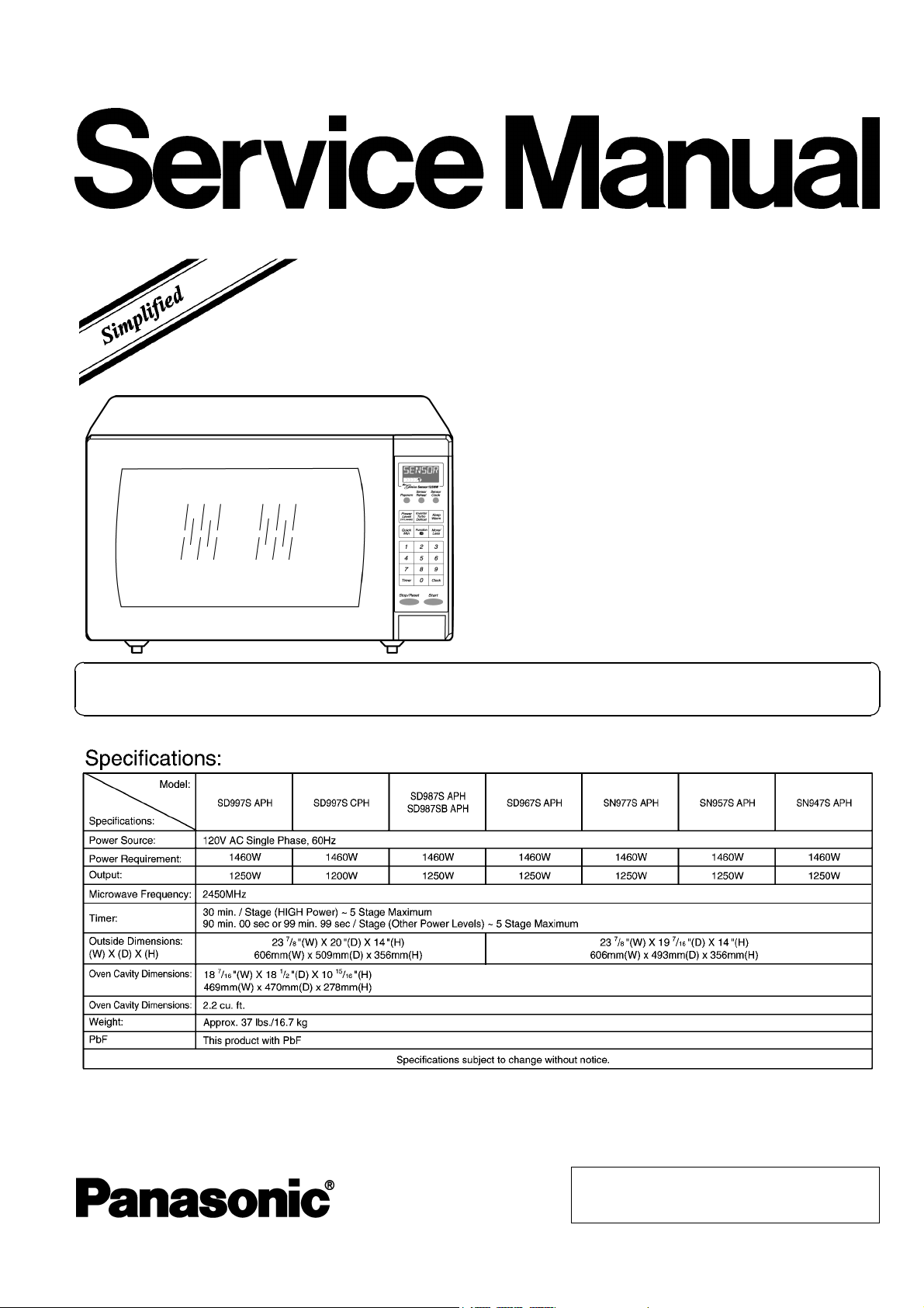
Microwave Oven
Please file and use this specified manual together with the service manual for Model NN-T695 (ORDER NO.
PHAMOS0501001C7).
© 2007 Panasonic Home Appliances Microwave
Oven (Shanghai) Co., Ltd. All rights reserved.
Unauthorized copying and distribution is a violation
of law.
NN-SD997S / NN-SD987S / NN-SD967S / NN-SN977S / NN-SN957S / NN-SN947S
2
NN-SD997S / NN-SD987S / NN-SD967S / NN-SN977S / NN-SN957S / NN-SN947S
3
NN-SD997S / NN-SD987S / NN-SD 967S / NN-SN 977S / NN-SN 957S / NN-SN947 S
CONTENTS
Page Page
1 SCHEMATIC DIAGRAM 5
1.1. APH
1.2. CPH
2 MEASUREMENTS AND ADJUSTMENTS
2.1. Adjustment of primary latch switch, secondary latch switch
and short switch.
2.2. Measurement of microwave output
3 PROCEDURE FOR MEASURING MICROWAVE ENERGY
LEAKAGE
3.1. Equipment
3.2. Procedure for measuring radiation leakage
3.3. Record keeping and notification after measurement
3.4. At least once a year, have the radiation monitor checked
for calibration by its manufacturer.
4 SIMPLE WAY OF H.V. INVERTER/MAGNETRON
TROUBLESHOOTING
5 H.V.INVERTER BOARD MAIN PARTS LIST (F606Y8M00AP)
5
6 EXPLODED VIEW AND PARTS LIST
6
7
7
7
8
8
8
8
8
9
6.1. EXPLODED VIEW
6.2. PARTS LIST
6.3. ESCUTCHEON BASE ASSEMBLY
6.4. PACKING AND ACCESSORIES
6.5. DOOR ASSEMBLY
6.6. WIRING MATERIALS
7 DIGITAL PROGRAMMER CIRCUIT
7.1. NN-SD997S APH/CPH, SD987S/SB APH
7.2. NN-SD967S APH
7.3. NN-SN977S APH
7.4. NN-SN957S APH
7.5. NN-SN947S APH
7.6. PARTS LIST
9
10
10
11
12
16
17
17
18
18
20
22
24
26
28
4
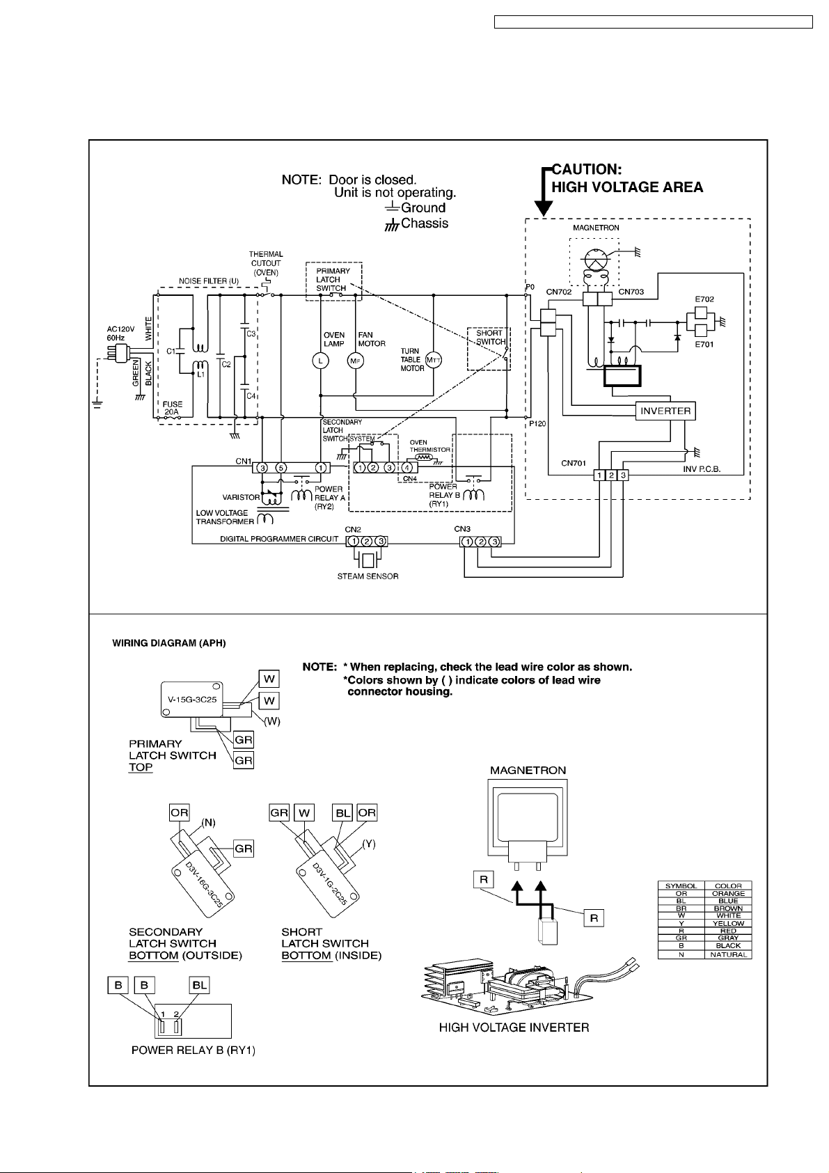
1 SCHEMATIC DIAGRAM
1.1. APH
NN-SD997S / NN-SD987S / NN-SD 967S / NN-SN 977S / NN-SN 957S / NN-SN947 S
5
NN-SD997S / NN-SD987S / NN-SD 967S / NN-SN 977S / NN-SN 957S / NN-SN947 S
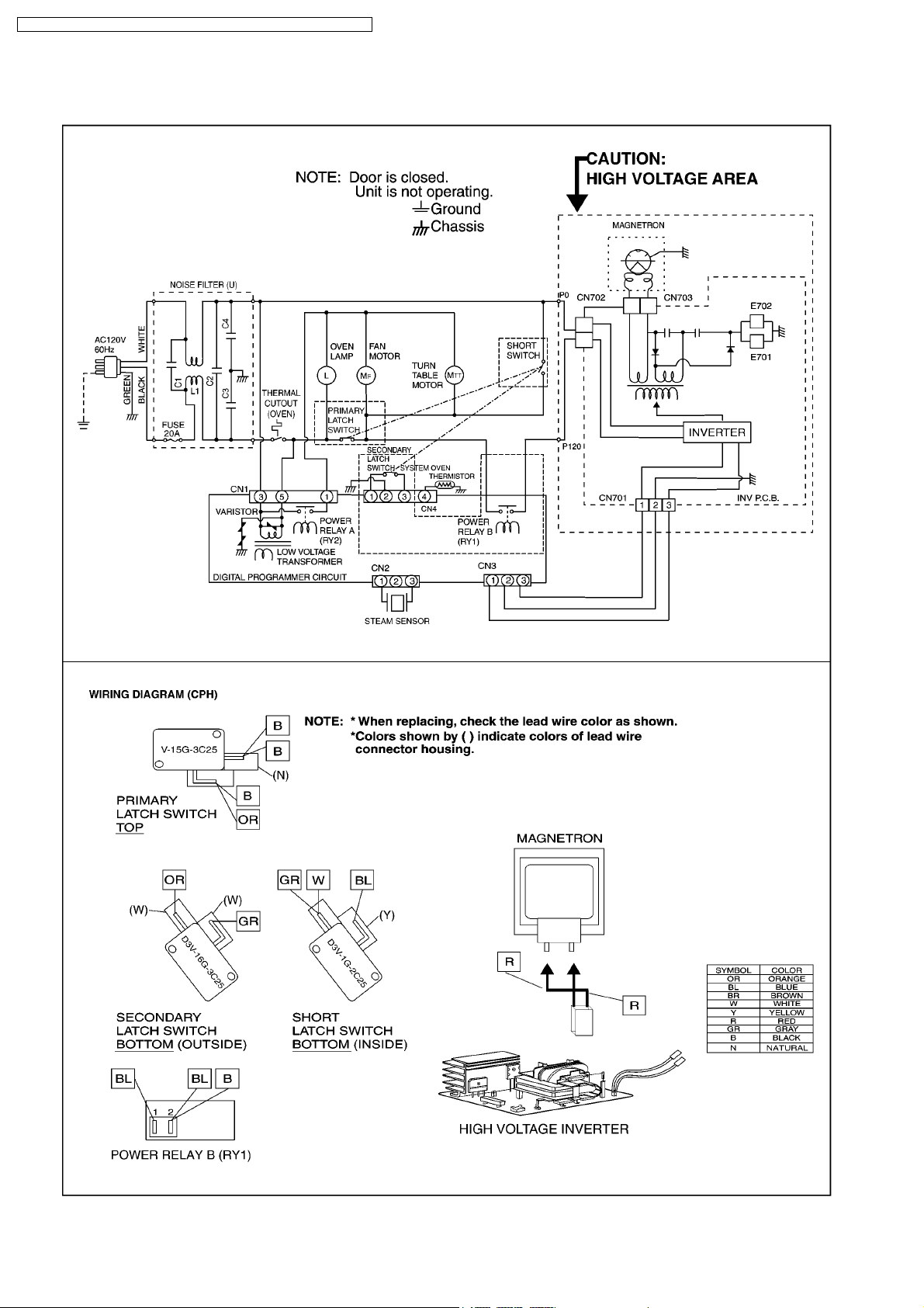
1.2. CPH
6
NN-SD997S / NN-SD987S / NN-SD 967S / NN-SN 977S / NN-SN 957S / NN-SN947 S
2 MEASUREMENTS AND ADJUSTMENTS
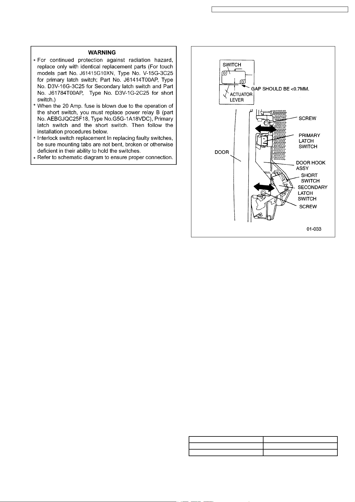
2.1. Adjustment of primary latch
switch, secondary latch switch
and short switch.
1. Mount the Primary latch switch, the Secondary latch switch
and the short switch to the door hook assembly as shown in
ILL.
NOTE:
No specific individual adjustments during
installation of the Primary latch switch, Secondary
latch switch or Short switch to the door hook are
required.
2. When mounting the door hook assembly to the oven
assembly, adjust the door hook assembly by moving it in
the direction of the arrows in the illustration so that the oven
door will not have any play in it. Check for play in the door
by pulling the door assembly. Make sure that the latch keys
move smoothly after adjustment is completed. Completely
tighten the screws holding the door hook assembly to the
oven assembly.
3. Reconnect the short switch and check the continuity of the
monitor circuit and all latch switches again by following the
component test procedures.
2.2. Measurement of microwave
output
The output power of the magnetron can be determined by
performing IEC standard test procedures. However,due to the
complexity of IEC test procedures, it is recommended to test
the magnetron using the simple method outlined below.
Necessary Equipment:
*1 liter beaker *Glass thermometer
*Wrist watch or stopwatch
NOTE:
Check the line voltage under load.Low voltage will
lower the magnetron output. Take the temperature
readings and heating time as accurately as possible.
1. Fill the beaker with exactly one liter of tap water.Stir the
water using the thermometer and record the water’s
temperature. (recorded as T1).
2. Place the beaker on the center of glass tray.
Set the oven for High power and heat it for exactly one
minute.
3. Stir the water again and read the temperature of the water.
(recorded as T2).
4. The normal temperature rise at High power level for each
model is as shown in table.
TABLE (1L-1min.test)
RATED OUTPUT TEMPERATURE RISE
1200W Min. 18.5°F(10.3°C)
1300W Min. 19.8°F(11.1°C)
7
NN-SD997S / NN-SD987S / NN-SD 967S / NN-SN 977S / NN-SN 957S / NN-SN947 S
3 PROCEDURE FOR MEASURING MICROWAVE ENERGY
LEAKAGE
3.2.1. Measurement with the outer panel
removed.
Whenever you replace the magnetron, measure for radiation
leakage before the outer panel is installed and after all
necessary components are replaced or adjusted. Special care
should be taken in measuring around the magnetron.
NOTE:
The U.S. Government standard is 5 mW/cm
customer’s home. 2mW/cm
voluntary standard. (1mW/cm
2
stated here is our own
2
for Canada)
2
while in the
3.1. Equipment
•••• Electromagnatic radiation monitor
•••• Glass thermometer 212°F or 100°C
•••• 600cc glass beaker
3.2. Procedure for measuring
radiation leakage
Note before measuring.
•••• Do not exceed meter full scale deflection. Leakage monitor
should initially be set to the highest scale.
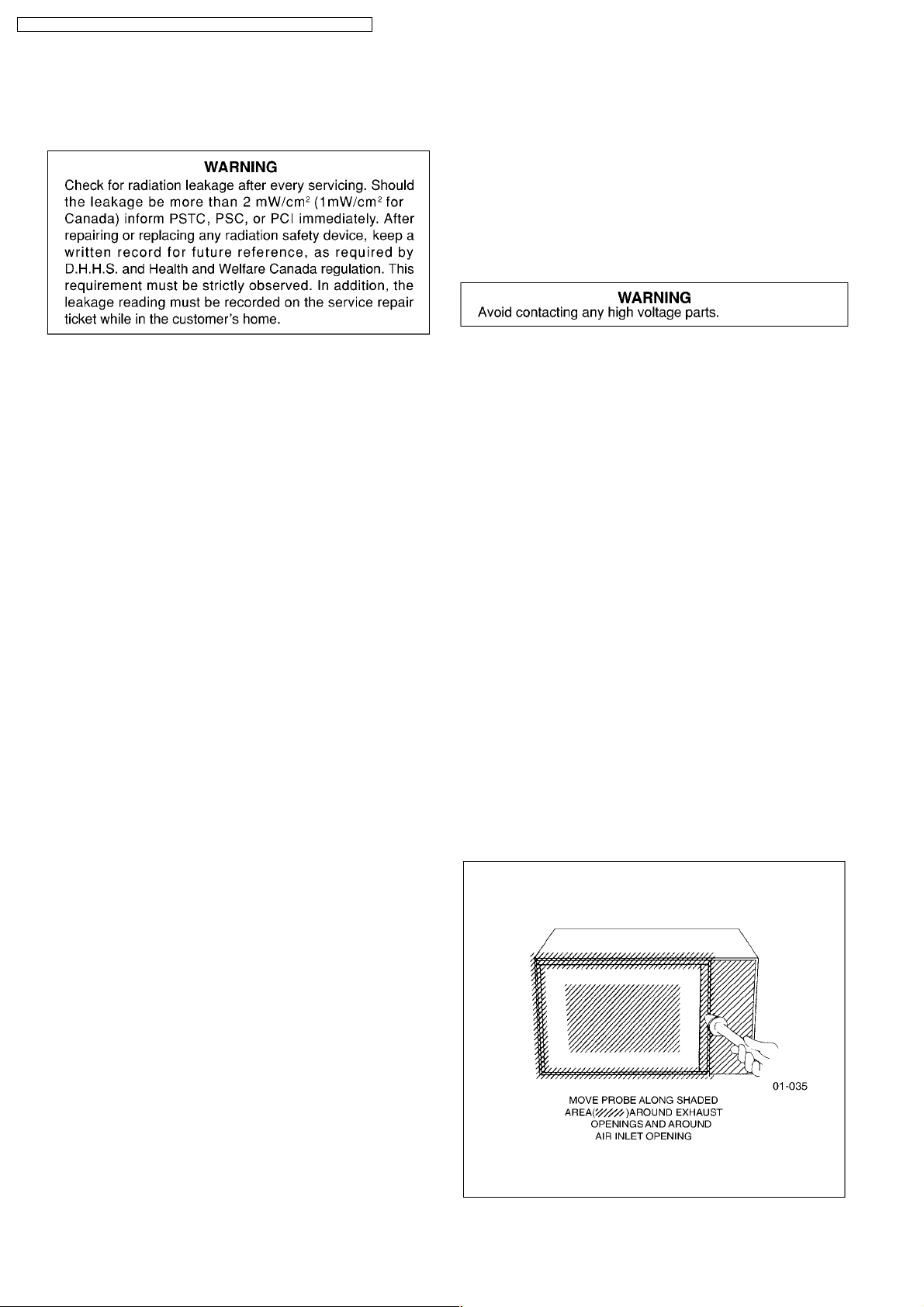
•••• To prevent false readings the test probe should be held by
the grip portion of the handle only and moved along the
shaded area in Figure no faster than 1 inch/sec
(2.5cm/sec).
•••• Leakage with the outer panel removed ...... less than
5mW/cm
•••• Leakage for a fully assembled oven with door normally
closed ...... less than 2mW/cm
•••• Leakage for a fully assembled oven [Before the latch switch
(primary) is interrupted] while pulling the door ...... less than
2mW/cm
1. Pour 275 ± 15cc (9ozs
water in a beaker which is graduated to 600cc, and place in
the center of the oven.
2. Set the radiation monitor to 2450MHz and use it following
the manufacturer´s recommended test procedure to assure
correct results.
3. When measuring the leakage, always use the 2 inch (5cm)
spacer supplied with the probe.
4. Tap the start pad or set the timer and with the magnetron
oscillating, measure the leakage by holding the probe
perpendicular to the surface being measured.
2
.
2
(1mW/cm2for Canada).
2
.
s
± 1/2oz) of 20°C ± 5°C (68° ± 9°F)
3.2.2. Measurements with a fully
assembled oven.
After all components, including outer panel are fully assembled,
measure for radiation leakage around the door periphery, the
door viewing window, the exhaust opening, control panel and
air inlet openings.
3.3. Record keeping and
notification after measurement
•••• After any adjustment or repair to a microwave oven, a
leakage reading must be taken. Record this leakage
reading on the repair ticket even if it is zero.
A copy of this repair ticket and the microwave leakage
reading should be kept by repair facility.
•••• Should the radiation leakage be more than 2 mW/cm
(1mW/cm2for Canada) after determining that all parts are in
good condition, functioning properly, and genuine
replacement parts as listed in this manual have been used,
immediately notify PSTC, PSC or PCI.
3.4. At least once a year, have the
radiation monitor checked for
calibration by its
manufacturer.
2
8
NN-SD997S / NN-SD987S / NN-SD 967S / NN-SN 977S / NN-SN 957S / NN-SN947 S
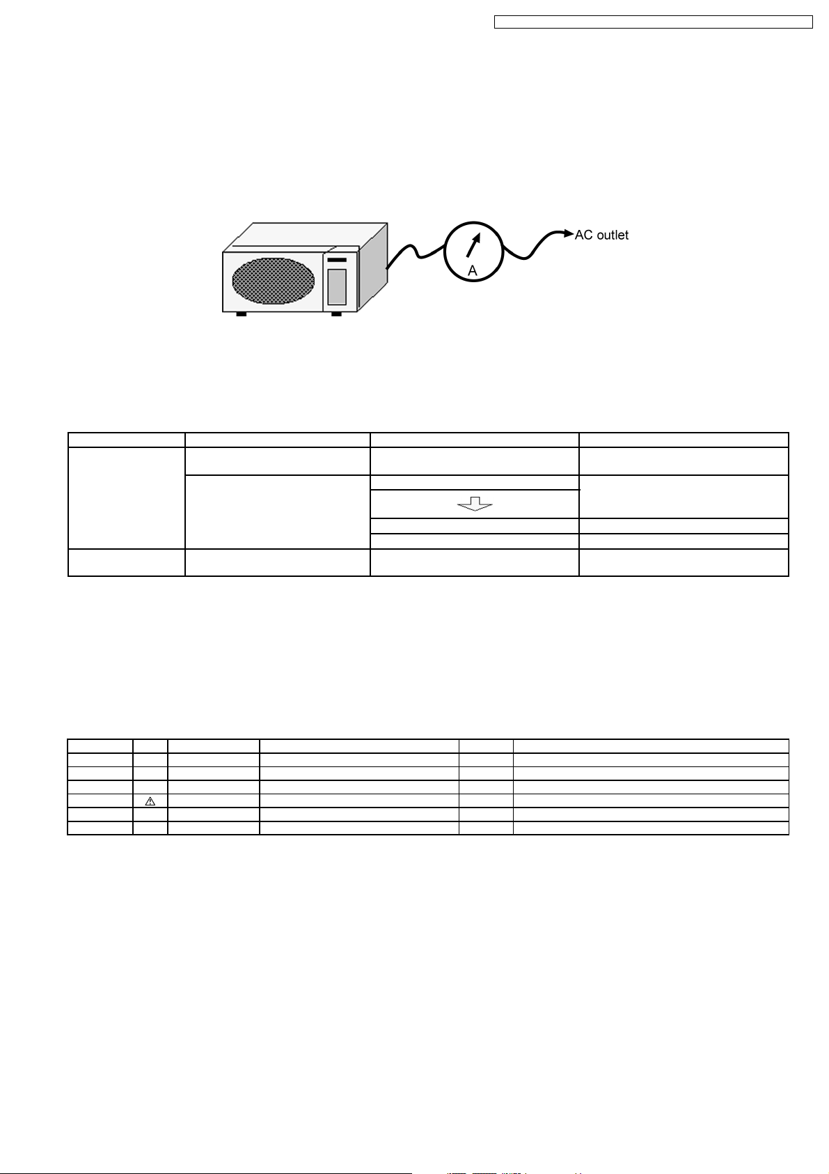
4 SIMPLE WAY OF H.V. INVERTER/MAGNETRON
TROUBLESHOOTING
Purpose:
Simple way (3/37 seconds rule) of identifying whether it’s Magnetron, Inverter, or others.
Set-up:
The unit under question is connected through the Ammeter as shown below.
Procedure:
Follow the matrix table below to identify the problem source.
Note:
Do not replace both Inverter board and Magnetron simultaneously and automatically without going through this
procedure.
Power will: Ammeter reading is: To do: Remedy:
Shut off in 37 seconds
after “Start”.
1. Between 0.5A and 1.0A. Check and repair open magnetron circuit Open magnetron wiring between Inverter
and magnetron terminal.
2. Between 1.0A and 2.0A. Check continuity of D702 in Inverter PCB.
1. D702 shorted Replace H.V.Inverter(F606Y8M00AP)
2. D702 is OK Replace magnetron
Shut off in 3 seconds
after “Start”
1. Less than 0.5A Check open circuit: Latch Switch, DPC,
Power Relay and CN701
Replace defective component(s), or
correct switch, cables and connectors.
5 H.V.INVERTER BOARD MAIN PARTS LIST
(F606Y8M00AP)
Ref. No. Part No. Part Name & Description Pcs/Set Remarks
DB701 B0FBBS000001 BRIDGE DIODE 1 20A, 600V
L701 F50206G00AP CHOKE COIL 1
Q701 B1JAGV000015 TRANSISTOR SI 1 1000V
T701 A609A8M00AP H.V. TRANSFORMER 1 (INCLUDING D701,D702,C706,C707)
C701 ECWF5284N300 CAPACITOR 1 0.28µF/500V
C702 ECWF2455N644 CAPACITOR 1 4.5µF/250V
9
 Loading...