

Panasonic NA-147VB6WGB, NA-147VB6WDE, NA-147VB6WNR, NA-147VB6WGN, NA-127VC6WFR Service Manual
...
© Panasonic Corporation 2015 Unauthorized copying and distribution is a violation of law.
Order No. VES1504001CE
Drum Type Washing Machine
Model No. NA-147VB6WGB
Model No. NA-147VB6WDE
Model No. NA-147VB6WGN
Model No. NA-147VB6WNR
Product Color : White
Destination : UK, Ireland, Germany, Austlia, Holland,
Belgium, Czech, Hungary, Romania,
Slovakia, Croatia, Serbia, Slovenia, Bosnia-Herzegovina, Sweden, Norway, Finland, Denmark
TABLE OF CONTENTS
PAG E PAG E
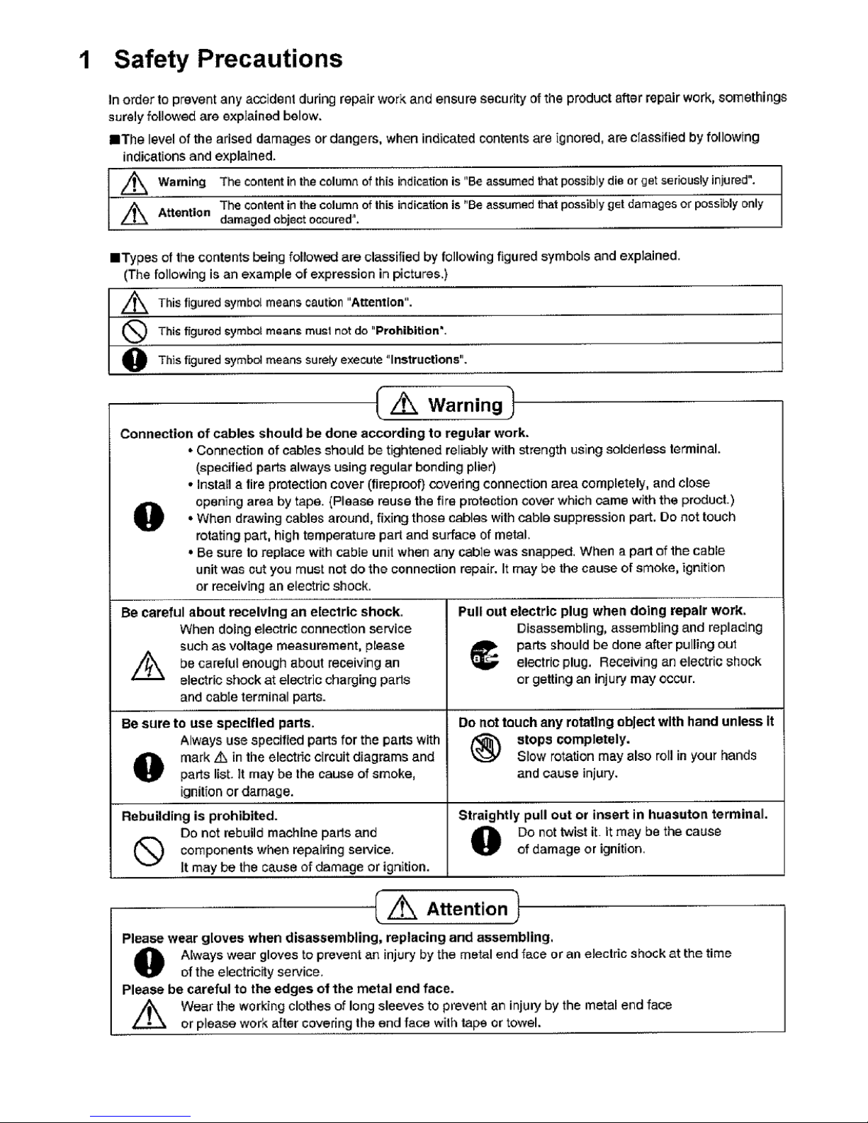
1 Safety Precautions ----------------------------------------------- 2
2 Specifications ----------------------------------------------------- 3
3 Location of Controls and Components ------------------- 5
4 Installation Instructions ---------------------------------------- 6
5 Operating Instructions------------------------------------------ 8
6 Test Mode ----------------------------------------------------------10
7 Service Mode -----------------------------------------------------12
8 Troubleshooting Guide ----------------------------------------13
9 Torque Values ----------------------------------------------------14
10 Disassembly and Assembly Instructions ---------------15
11 Component Specifications-----------------------------------26
12 Wiring Connection Diagram ---------------------------------34
13 Exploded View and Replacement Parts List -----------36
2

3
2. Specifications
2.1. Product Specifications
Model NA-147VB6
Product Type Front Loader
Capacity 7 kg
Max Spin Speed 1400 rpm
Drum Volume 50 lt
Energy Label Rating A+++
Energy Consumption 162 kWh / annum
Water Consumption 9240 L / annum
Noise Level
Wash 58 dBA
Spin 76 dBA
Control Panel LCD Display
Wash Programs 15 settings
Spin Speed Setting 7 setting
Dimensions
Height 84,5 cm
Width 59.7 cm
Depth 52.7 cm
Door Opening Large door opening
Delay Time Setting Yes
Colour White
Water Protection Overflow Protection
Other Features Child Lock
Packaging Shrink package
2.2. Name Plate

4
2.3. Dimension in millimetres
NA-147VB6

5
3. Location of Controls and Components

6
4. Installation Instructions
4.1. Moving and Installing
4.1.1. Removal of Transportation Screw
1. Transportation screws, which are located at the back side of
the machine, must be removed before running the machine.
2. Loosen the screws by turning them anticlockwise with a
suitable spanner.
4.1.2. Foot Adjustment
1. Do not install machine on rugs or similar surfaces.
2. For machine to work silently and without any vibration, it should be
installed on a flat, non-slippery firm surface. Any suspended floor
must be suitably strengthened.
3. You can adjust the level of machine using its feet.
4. First, loosen the plastic adjustment nut away from the cabinet
base.
5. Change the level by adjusting the feet upwards or downwards.
6. After level has been reached, tighten the plastic adjustment nut
again by rotating it upwards against the base of the cabinet.
7. Never put cartons, wooden blocks or similar materials under the
machine to balance irregularities of the floor.
3. Pull out the screws and rubber washers.
4.1.3. Electrical Connection
1. Washing machine requires a 50Hz supply of 220-240Volts.
2. A special earthed plug has been attached to the supply cord of
washing machine. This plug must be fitted to an earthed socket. The
fuse value fitted to this plug should be 13 amps. If you have any
doubts about electrical supply, consult a qualified electrician.
THIS APPLIANCE MUST BE EARTHED.
Insert the machine’s plug to a grounded socket which
you can easily reach.
4. The holes where the transport screws have been removed
should be covered with the plastic transport caps found in the
accessories bag.
5. The transportation screws that have been removed from the
machine must be re-used in any future transporting of the
machine.

7
4.1.4. Water Supply Connection
1. Washing machine is supplied with a single (cold) water inlet.
2. To prevent leakage from the connection joints, a rubber
washer is included in the hose packing. Fit this washer at the
end of water inlet hose on the tap side.
3. Connect the hose to the water inlet valve. Tighten the plastic
connector by hand. Please call a qualified plumber if you are
unsure about this.
4. Water pressure of 0,1-1 MPa from tap will enable machine to
work more efficiently.(0,1 MPa pressure means water flow of
more than 8 litres in 1 minute from a fully opened tap)
5. After connection is complete, check for leakage by turning on
tap completely.
6. Make sure that water inlet hoses can not become folded,
damaged, stretched or crushed when the washing machine is in
its final position.
7. Mount the water inlet hose to a ¾” threaded water tap.
4.1.5. Drain Connection
1. Make sure that water inlet hoses are not folded, twisted,
crushed or stretched.
2. The drain hose should be mounted at a minimum height of 60
cm, and a maximum height of 100 cm from the floor.
3. The end of the drain hose can be connected directly to a
drainage stand-pipe or alternatively to a specific connection point
designed for that purpose on the waste outlet of a sink unit.
4. Do not extend the drain hose or guarantee will be invalidated.
4.2 Detergent Box Group
PREWASH = WATER ENTRY VALVE 1
MAIN = WATER ENTRY VALVE 2
SOFTENER = WATER ENTRY VALVE 1 + VALVE 2
MAIN
SOFTENER
PREWASH
VALVE1
VALVE2
VALVE1

8
5. Operating Instructions
5.1. LCD Screen, Function Buttons & Knobs
PR Program selector 16 programs including off position
SW1 Switch 1, Start / Pause
SW2 Switch 2, Temperature Selection
SW3 Switch 3, Spin Speed Selection
SW4 Switch 4, Delay Timer Selection
SW5 Switch 5, Extra Rinse Option
SW6 Switch 6, Easy Ironing Option
SW7 Switch 7, Eco/Speed Mode Option
SS1 7 Segment LCD for Temperature Display I8 Extra Rinse Symbol
SS2 7 Segment LCD for Spin Speed Display I9 Easy Ironing Symbol
SS3 7 Segment LCD for Remaining Time I10 Eco Mode Symbol
I1 Child Lock Symbol I11 Speed Mode Symbol
I2 Door Lock Symbol I12 Cold Wash Symbol
I3 Drain Phase Symbol I13 Temperature Sign
I4 Spin Phase Symbol I14 Program Proceeding Zone
I5 Rinse Phase Symbol Slow Blink ON 0.5 sec, OFF 0.5 sec, ON 0.5 sec
I6 Wash Phase Symbol Fast Blink ON 0.10 sec, OFF 0.10 sec, ON 0.10 sec
I7 Delay Symbol
SW1 SW2 SW3 SW4 SW5 SW6 SW7 PR
I6 I5 I4 I3 I2 I1
SS1 SS2 SS3 I7 I8 I9 I10 I11I12 I13
I14

9
5.2. Program Details

10
5.3. Child Lock
Activation
Press SW7 for 5 seconds.
The Child Lock Symbol on appears on the LCD display as Child
Lock is active.
Deactivation
Press SW7 for 5 seconds.
The Child Lock Symbol will disappear on LCD displayupon
deactivation.
6. Test Mode
6.1. Autotest
Set PR to program 3 (Colours)
While pressing SW5 (Extra Rinse), change position of the PR from
third program to second (Cotton-Prewash), and release SW5.
Autotest starts.
 Loading...