

Page 1
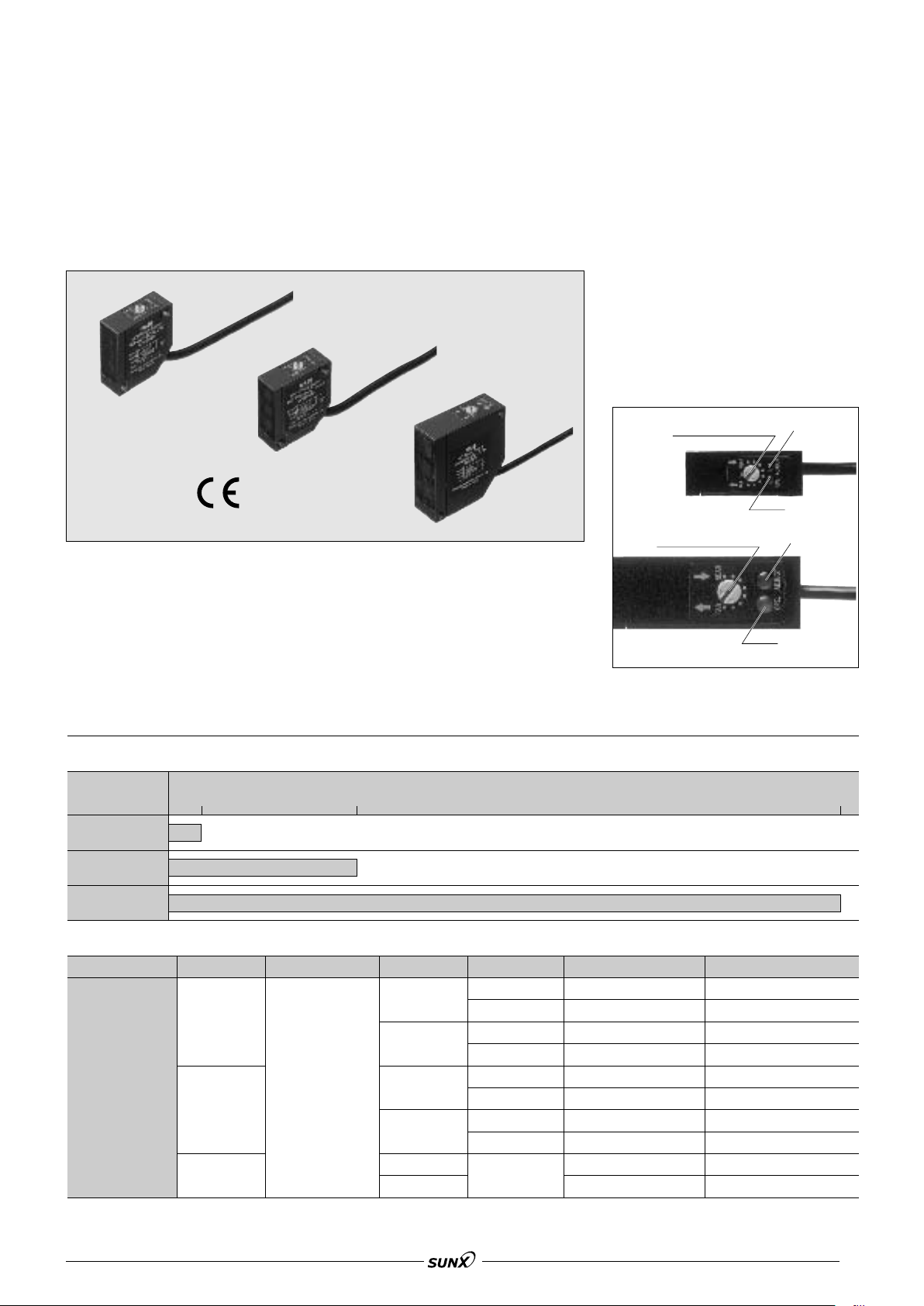
Operation
Indicator LED
MQ-W3 type
MW-W20 type
Distance adjustment dial
Adjustment
indicator LED
Adjustment
indicator LED
Operation
Indicator LED
MQ-W70 type
Distance adjustment dial
MQ-W
08/2005
SERIES
Triple Beam Trigonometric
Area Reflective Photoelectric Sensors
Very accurate detection by triple beam triangulation sensing method in a compact package.
Environmental resistance
Immersion protected construction
(equivalent to IEC IP67)
High speed detection: Max. 2 ms
Light-ON/Dark-ON output is wire
selectable.
Operating voltage of 12 to 24 V DC
Adjuster and Indicators
(Comply with EMC directive MQ-W-EM type only)
FEATURES
Accurate detection regardless of
color, material, or shape of objects
Area reflective type sensor can detect
white or black object at the same distance. In case of diffuse reflective type,
it is difficult to detect objects of various
color with the same sensitivity setting.
MQ-W area reflective type sensor is
useful for such a case.
No-miss operation regardless of
back-grounds
Area reflective type sensor does not
detect objects beyond the set range.
Resistant to lens surface soiling
Area reflective type sensor detects the
distance by the angle, not the intensity
of received light. Even if the lens surface is soiled by dust or any powdery
material, there is a little variation of
sensing range.
SENSING RANGES
Sensing range (m ft.)
0.03 .098 0.2 .656 0.7 2.297
MQ-W3 types
MQ-W20 types
MQ-W70 types
PRODUCT TYPE
Detection method
Triple beam area
reflective type
1
These suffix EM types conform to CE. These types have the grounding connection inside of housing
*
Range
0.03 m .098 ft.
0.2 m .656 ft.
0.7 m 2.297 ft.
Rated operating voltage
12 to 24 V DC
Control output Light source Part number *1 CE types
NPN
PNP
NPN
PNP
NPN
PNP
Infrared LED MQ-W3A-DC12-24V
Red LED
Infrared LED
Red LED
Infrared LED
Red LED
Infrared LED
Red LED
Infrared LED
MQ-W3AR-DC12-24V
MQ-W3C-DC12-24V
MQ-W3CR-DC12-24V
MQ-W20A-DC12-24V
MQ-W20AR-DC12-24V
MQ-W20C-DC12-24V
MQ-W20CR-DC12-24V
MQ-W70A-DC12-24V
MQ-W70C-DC12-24V
MQ-W3A-DC12-24VEM
MQ-W3AR-DC12-24VEM
MQ-W3C-DC12-24VEM
MQ-W3CR-DC12-24VEM
MQ-W20A-DC12-24VEM
MQ-W20AR-DC12-24VEM
MQ-W20C-DC12-24VEM
MQ-W20CR-DC12-24VEM
MQ-W70A-DC12-24VEM
MQ-W70C-DC12-24VEM
266
Page 2
SPECIFICATIONS
08/2005
1) Ratings
MQ-W
Operating side
Rated operating voltage
Rated current consumption
Output current capacityLoad side
12 to 24 V DC
30 mA or less (excluding load)
100 mA or less
2) Performance
Detection principle Triple beam triangulation sensing method
Detection method Area reflective type
Type Amplifier selfcontained DC type
MQ-W3A-DC12-24V
Part number
Sensing range 0.03 m .098 ft. 0.2 m .656 ft. 0.7 m 2.297 ft.
Detectable distance 0.02 to 0.04 m .066 to .131 ft. 0.04 to 0.2 m .131 to .656 ft. 0.2 to 0.7 m .656 to 2.297 ft.
Standard target
Detectable target Opaque, translucent
Hysteresis 10% or less the set range 20% or less of the set range
Operating voltage range 9.6 to 30 V DC ripple (P-P) included
Response time (freq.) 2 ms or less (250 times per second or less)
Initial insulation resistance Min. 20 MΩ between a lead wire and external housing (at 500 V DC)
Initial breakdown voltage Between a lead wire and external housing: 500 Vrms for 1 min
Vibration resistance 10 to 55 Hz (1 cycle/min), double amplitude 1.5 mm .059 inch (2 h each on 3 axes)
Shock resistance 980 m/s2{approx. 100 G} (6 times each on 3 axes)
Protective construction Diecast case immersion protected (equivalent to IEC IP67)
Usable ambient
light level
Ambient temperature –25 to 55°C –13 to +131°F (non-icing condition)
Ambient humidity Max. 85% RH (non-condensing condition)
Storage temperature –25 to 55°C –13 to +131°F
Indicator
Light source
Note: Unless otherwise specified, the measurement conditions comprise rated operating voltage, power supply by battery, 20°C 68°F ambient
temperature, standard target and 200 lux or less illuminance on the receiver surface.
Incandescent lamp
Sunlight 30,000 lux or less
MQ-W3AR-DC12-24V
MQ-W3C-DC12-24V
MQ-W3CR-DC12-24V
White drawing paper
11 cm .394.394 inch
Operation indicator: Red LED ON with light entry
Adjustment indicator: Red LED ON with sufficient volume of lights
Infrared LED/Red LED (R is added to the suffix of W3(20)A(C) in the part No.)
MQ-W20A-DC12-24V
MQ-W20AR-DC12-24V
MQ-W20C-DC12-24V
MQ-W20CR-DC12-24V
White drawing paper
22 cm .787.787 inch
10,000 lux or less
MQ-W70A-DC12-24V
MQ-W70C-DC12-24V
White drawing paper
7.57.5 cm 2.9532.953 inch
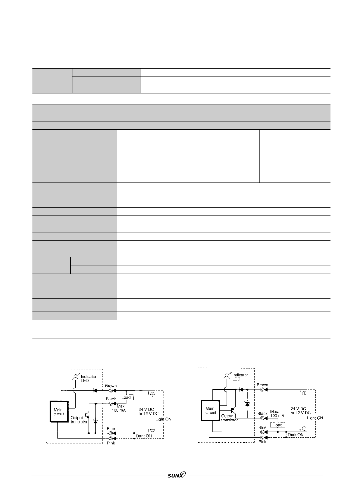
3) Output circuit diagram
NPN Output type PNP Output type
267
Page 3

MQ-W
40
.131
For 40 mm .131 ft.
For 30 mm .098 ft.
For 20 mm .066 ft.
Operating range (mm)
(inch)
Moving direction
Standard target
(white drawing paper
10×10 mm .394×.394 inch)
(mm)
(ft.)
Operating
distance
30
.098
20
.066
10
.394
10
.394
5
.1975.197
0
200
.656
150
.492
100
.328
50
.164
For 150 mm .492 ft.
For 200 mm .656 ft.
For 100 mm .328 ft.
For 50 mm .164 ft.
Operating range (mm)
(inch)
Moving direction
Standard target
(white drawing paper 20×
20 mm .787×.787 inch)
(mm)
(ft.)
Operating
distance
10
.394
10
.394
5
.1975.197
0
200
.656
600
1.969
400
1.312
For 500 mm 1.641 ft.
For 700 mm 2.297 ft.
For 300 mm .984 ft.
Operating range (mm)
(inch)
Moving direction
Standard target
(white drawing paper 75×
75 mm 2.953×2.953 inch)
(mm)
(ft.)
Operating
distance
10
.394
10
.394
5
.1975.197
0
(mm
inch)
2.5 dia.
.098
2.3 dia.
.091
4.0 dia.
.157
(mm ft.)20
.06630.09840.131
0
(mm
inch)
6.9 dia.
.272
6.7 dia.
.264
7.4 dia.
.291
8.3 dia.
.327
(mm ft.)100
.328
50
.164
150
.492
200
.656
0
(mm
inch)
23.0 dia.
.906
33.0 dia.
1.299
39.0 dia.
1.535
(mm ft.)300
.989
500
1.641
700
2.287
0
10
0.015
20
.066
30
.098
40
.131
0
100
0.155
Distance setting 40 mm
.131 ft.
Distance setting 30 mm
.098 ft.
Distance setting 20 mm
.066 ft.
Target size (mm
2
inch2)
Distance range (mm ft.)
Standard target
(white drawing paper 10×10 mm
.394×.394 inch)
100
.328
200
.656
300
.984
400
1.132
500
1.641
600
1.969
Distance range (mm ft.) × : Impossible
Former pruduct
White drawing
paper
Corrugated
carton
Veneer panel
Black rubber
Black frosted
finish
Aluminum
panel
Mirror
Copper clad
printed circuit
board
×
×
Triple beam type (MQ-W20A)
10
.03320.06630.09840.131
Distance range (mm ft.)
White
drawing
paper
Black
drawing
paper
Corrugated
paper
Veneer panel
Black rubber
Non-glossy target
Semi-glossy target
Glossy target
Mirror
Blue acrylic
White acrylic
Copper clad
printed circuit
board
50
.164
100
.328
150
.492
200
.656
Distance range (mm ft.)
White
drawing
paper
Black
drawing
paper
Corrugated
paper
Veneer panel
Black rubber
Non-glossy target
Semi-glossy target
Glossy target
Mirror
Blue acrylic
White acrylic
Copper clad
printed circuit
board
1000
1.55
100
.328
200
.656
0
100
0.155
Distance setting 200 mm
.656 ft.
Distance setting 100 mm
.328 ft.
Distance setting 40 mm
.131 ft.
Target size (mm
2
inch2)
Distance range (mm ft.)
Standard target
(white drawing paper 20×20 mm
.787×.787 inch)
1,000
1.55
100
.328
200
.656
300
.984
400
1.312
500
1.641
600
1.969
700
2.297
0
10,000
15.5
Distance setting 700 mm
2.297 ft.
Distance setting 400 mm
1.312 ft.
Distance setting 200 mm
.656 ft.
Target size (mm
2
inch2)
Distance range (mm ft.)
Standard target
(white drawing paper 75×75 mm
2.953×2.953 inch)
08/2005
DATA
1. Operating range characteristics
MQ-W3 types MQ-W20 types MQ-W70 types
2. Projector beam diameter characteristics
Light beam diameter is determined as the region where the amount of light is decreased to 1/e2(e]2.72) when the largest amount of light is
assumed as 1.
MQ-W3 types MQ-W20 types MQ-W70 types
3 Detectable target characteristics
MQ-W3 types MQ-W20 types MQ-W70 types
4. Material characteristics
Comparision between MQ-W20A and former product
Condition: Target (4060 mm 1.5752.362 inch),
target assumed as natural shape
For the former product (diffuse reflective type),
depending upon the object material, the operating
range varied greatly, but for the triple beam type
there a little variation.
MQ-W3 types
Condition: Target (4060 mm 1.5752.362
inch), natural shape
MQ-W20 types
Condition: Target (4060 mm 1.5752.362
inch), natural shape
268
Page 4

DIMENSIONS mm inch
12.2
.480
11.7
.461
3.3
.130
2,000
78.74
3.3
.130
3.3
.130
4.4
.173
4.4
.173
44.8
1.764
24
.945
10.9
.429
1.4
.055
4
.157
16.6
.654
25.4
1 inch
4
.157
2.2
.087
10.7
.421
6.3
.248
7.3
.287
24.4
(1 inch)
(17)
(.669)
25.4±0.2
1 inch
25.4±0.2
1 inch
6.3
.248
32
1.260
6.3
.248
1
.039
4.2 DIA.
.165
12.6
.496
Distance adjustment dial Operation indicator LED
2-M4 (P = 0.6) tapped
M.S.:* M4 or #6
Adjustment indicator LED
Dimensions with the mounting bracket**
attached
Outline dimensions
12.2
.480
3.3
.130
2,000
78.74
3.3
.130
3.3
.130
4.4
.173
4.4
.173
44.8
1.764
24
.945
10.9
.429
1.4
.055
4
.157
16.6
.654
25.4
1 inch
4
.157
2.2
.087
10.7
.421
6.3
.248
7.3
.287
24.4
(1 inch)
(17)
(.669)
25.4±0.2
1 inch
25.4±0.2
1 inch
7.5
.295
7.5
.295
10.5
.413
32
1.260
1
.039
4.2 DIA.
.165
12.6
.496
Distance adjustment dial Operation indicator LED
2-M4 (P = 0.6) tapped
M.S.:* M4 or #6
Adjustment indicator LED
Dimensions with the mounting bracket**
attached
Outline dimensions
18.2
.717
2,000
78.74
3.5
.138
3.5
.138
3.5
.138
4.4
.173
4.4
.173
4
.157
68.2
2.685
12.5
.492
12.5
.492
24
.945
12.4
.488
1.6
.063
17.4
.685
36.6
1.441
45
1-49/64
45.0
1.772
12.7
.500
4.5 DIA.
.177
9.1
.358
8.1
.319
44
(1-3/4 inch)
(22)
(.866)
45±0.2
1-49/64
45±0.2
1-49/64
13
.512
13
.512
15.5
.610
52
2.047
1
.039
4.2 DIA.
.165
18.6
.732
Distance adjustment dial Operation indicator LED
2-M4 (P = 0.6) tapped
M.S.:* M4 or #6
Adjustment indicator LED
Dimensions with the mounting bracket**
attached
Outline dimensions
08/2005
1. MQ-W3 types
MQ-W
2. MQ-W20 types
3. MQ-W70 types
General tolerance:
±0.5 .020
General tolerance:
±0.5 .020
CONNECTING DIAGRAM
*M.S.: mounting screw
Make connection to B side with pink wire for
Light ON
Make connection to v side with pink wire for
Dark ON
Note: When switching a power source, make
ground connection to the frame ground terminal or to the ground terminal. This will assure
more stable operation.
General tolerance:
**The mounting bracket is enclosed in the inner carton.
Operating condition
With light
intercepted ON
With light
entering ON
Lights with light entering
Output transistor
Operation
indicator LED
±0.5 .020
Common use
269
Page 5

MQ-W
08/2005
OPERATING PRINCIPLES
Detection principle of new triple beam area reflective series
$ Optical triangulation sensing method
The light beam projected by the LED,
passing through the condensing lens of
the light projector, is applied to the surface of the target to be detected. One
part of the diffused reflected light rays
passes through the light receiver lens
producing a spot on the position sensitive device. When the detectable target
is at a position A that is at a compara-
$ Triple beam type range sensing principle
The MQ photoelectric sensor area
reflective type has adapted this optical
triangulation range measurement principle, but in order to improve the reliability of the detection of the sensor, a
more elaborate method has been
devised. First, light receivers are positioned symmetrically on either side of
the axis of the light projector, composing a triple beam arrangement. As
shown in Fig. 2, when the moving
detectable target is at the edge of the
projected light beam, the spot reflected
from the target is at a location different
tively near distance as shown in Fig. 1,
a spot is produced at (a). When the target is at a position B that is far, a spot
is produced at (b). Accordingly, if any
spot position on the position sensitive
device is detected, the distance to the
target can be determined. This is the
principle of optical triangulation range
measurement.
from the point where the spot is produced when the beam is completely
intercepted, generating a range measurement difference of +
the triple beam composition, the symmetrically arranged position sensitive
device (2) has a spot produced conversely at a –
and by means of averaging both range
measurement signals, the correct range
measurement can be made. This
results in significantly improved
repeatability and background suppression.
∆
X difference position,
∆
X, but with
Fig. 1 Optical triangulation range
measurement method
Other examples of this method are
the automatic focusing and camera
range measurement systems.
Fig. 2 Triple beam range measurement method
By averaging the range measurement signals of the 2 light receiving
systems, the range measurement
difference is cancelled.
$ Optical system of the triple beam photoelectric sensor
In the MQ photoelectric sensor area
reflective type, it is necessary to give
special consideration to the lens. In
order to improve the precision, an
aspherical lens, having limited spherical
and coma aberration, is used.
In addition, as shown in Fig. 4, a photo
diode having 2 output terminals is used.
By comparing the output currents from
the 2 PSDs, there is no relationship to
the level of the incident light. Thus, the
ratio of reflection from the detectable
target exerts no influence and the
range measurement and detection can
be interpreted accuracy.
Fig. 3 Light beam trace of the lens
(a) is a spherical lens, and (b) is the
aspherical lens. Because there is no
aberration in (b), range measurement precision is high.
$ Operating principle of area reflective method
The operation of the MQ photoelectric
sensor area reflective type is explained
in Fig. 5. After the output from the 2
PSD elements is added, the I/V value is
converted and the logarithm determined. By subtraction, the distance signal in (I
1/I2) is obtained. This can be
optionally set, and with the distance
adjustment control, comparison with the
produced value can be made to detect
whether the target is or is not within the
distance range.
Fig. 4 PSD (position sensitive
device) construction
By making a calculation of the ratio
of I
1 and I2, the light spot position
can be detected.
Fig. 5 Signal processing circuit block diagram
270
Page 6

CAUTIONS
Operation
Indicator LED
MQ-W3 type
MW-W20 type
Distance adjustment dial
Adjustment
indicator LED
Adjustment
indicator LED
Operation
Indicator LED
MQ-W70 type
Distance adjustment dial
08/2005
MQ-W
These products are not
safety sensors and are
not designed or intended
to be used to protect life
and prevent bodily injury
or property damage.
1. Ambient environment
1) Use within the range of ambient
temperature of –25 to +55°C –13 to
+131°F.
2) Use within a range of 9.6 V to 30 V
DC (ripple P-P included) for operating
voltage.
3) Use with an ambient light level at the
light receiving surface of less than
10,000 lux for incandescent lamp and
less than 30,000 lux for sunlight.
4) Use a surge absorber as the internal
circuit may be damaged if external
surge voltage exceeds 500 V
[±(1.250) µs of single polarity fullwave voltage].
5) Avoid using in a location with high
concentrations of steam, dust, or corrosive gas.
6) The sensor is of immersion protected
type, but this does not mean that it can
be used in water or where there is
direct impingement of rain for detecting
objects.
2. Connections
1) Check all wiring before applying
power since incorrect wiring may damage the internal circuit.
2) Use a load relay with a rated operating voltage of 12 V DC or 24 V DC. The
voltage applied to the load relay is the
operating voltage of the photoelectric
sensor minus the internal voltage drop
(1.2 V). Voltage fluctuations should be
taken into account.
3) If a load greater than 100 mA is connected, the output section will be
damaged, so sufficient care should be
taken.
4) If the wiring to the photoelectric sensors run parallel to high voltage or
power lines, due to inductive noise,
mis-operation or damage can occur.
Wiring should be run in separate.
5) Wire 0.3 mm
2
.0005 inch2AWG22 or
larger should be used for wiring up to a
length of 100 m 328 ft..
6) When the photoelectric sensors
being mounted, if the unit is struck by a
hammer or other heavy tool, the function can be impaired. Sufficient care
should be taken.
7) The changeover from Light-ON (light
entry ON) to Dark-ON (light intercepted
OFF) can be carried out with the pink
lead wire. For Light-ON, connect the
pink wire to the B side, and for DarkON, connect the pink wire to the v
side.
3. Distance adjustment
1) Set the detecting surface of the photoelectric sensor in the detecting direction and temporarily fasten it.
2) While no target in the detection
region, set the distance adjustment dial
to maximum (FAR) and slowly turn it
counterclockwise.
Continue turning the control counterclockwise until the operation indicator
LED (OPE.) is extinguished. This is the
adjustment position. If the indicator
LED is extinguished at the maximum
position, that is the adjustment position.
3) With target in the detection area, set
the dial in the minimum position
(NEAR) and turn the control clockwise
to locate the position where the indicator LED turns ON. If the indicator LED
goes ON at the minimum position, then
NEAR is the adjustment position.
4) Set the control to a point midway
between the locations found in 2) and
3) above.
5) Securely fasten the photoelectric
sensor. When fastening, the sensor
should be sufficiently secure so that it
will not shift under vibration of shock.
Notes:
1. If the adjustment indicator LED does
not light in the adjustment of 3) as prescribed, or if the position between 2)
and 3) is less than 2 graduations,
change the position of the detection
surface and repeat the procedure of 1)
to 4), or try to determine the source of
external factors such as variation in
ambient temperature, variation in target
position, etc., that creating the problem.
2. The difference in detection distance
due to the colors of the target is virtually non-existent, but if the actual target is
one where the reflectivity is extremely
low (target which have a frosted finish
produced by black rubber), or where
the reflectivity is extremely high (mirror,
glass, or truly reflectting target), confirmation should be done with the actual
target.
4. Detector
1) Keep the detector surface clean as
excessive dust or dirt on the detector
surface will decrease the margin of the
distance range.
2) The front surface of the lens is made
of polycarbonate. This material is resistant to water, weak acids and alkalis,
aliphatic hydrocarbons, oils, etc., but it
is not resistant to ketones, esters, halogenated hydrocarbons, or aromatic
hydrocarbons.
271
 Loading...