

Page 1

MICROCOMPUTER MN103S
MN103S927/92A/F92G
LSI Application Notes Excerption
Pub.No.3329211-010E
Page 2

Page 3

Request for your special attention and precautions in using the technical information and
semiconductors described in this book
(1) If any of the products or technical information described in this book is to be exported or provided to non-residents, the
laws and regulations of the exporting country, especially, those with regard to security export control, must be observ ed.
(2) The technical information described in this book is intended only to show the main characteristics and application circuit
examples of the products, and no license is granted under any intellectual property right or other right owned by our
company or any other company. Therefore, no responsibility is assumed by our company as to the infringement upon any
such right owned by any other company which may arise as a result of the use of technical information described in this
book.
(3) The products described in this book are intended to be used for standard applications or general electronic equipment
(such as office equipment, communications equipment, measuring ins truments and household appliances).
Consult our sales staff in advance for information on the following applications:
x Special applications (such as for airplanes, aerospace, automobiles, traffic control equipment, combustion equipment,
life support systems and safety devices) in which exceptional quality and reliability are required, or if the failure or
malfunction of the products may directly jeopardize life or harm the human body.
x Any applications other than the standard applications intended.
(4) The products and product specifications described in this book are subject to change without notice for modification and/
or improvement. At the final stage of your de sign, pur chasing, o r use of the p roducts, therefore , ask for the mo st up-todate Product Standards in advance to make sure that the latest specifications satisfy your requirements.
(5) When designing your equipment, comply with the range of absolute maximum rating and the guaranteed operating condi-
tions (operating power supply voltage and operating environment etc.). Especially, please be careful not to exceed the
range of absolute maximum rating on the transient state, such as power-on, power-off and mode-switching. Otherwise,
we will not be liable for any defect which may arise later in your equipment.
Even when the products are used within the guaranteed values, take into the consideration of incidence of break down
and failure mode, possible to occur to semiconductor products. Measures on the systems such as redundant design,
arresting the spread of fire or preventing glitch are recommended in order to prevent physical injury, fire, social damages, for example, by using the products.
(6) Comply with the instructions for use in order to prevent breakdown and characteristics change due to external factors
(ESD, EOS, thermal stress and mechanical stress) at the time of handling, mounting or at customer's process. When
using products for which damp-proof packing is required, satisfy the conditions, such as shelf life and the elapsed time
since first opening the packages.
(7) This book may be not reprinted or reproduced whether wholly or partially, without the prior written permission of Mat-
sushita Electric Industrial Co., Ltd.
PanaXSeries is a trademark of Matsushita Electric Industrial Co., Ltd.
The other corporation names, logotype and product names written in this book are trademarks or registered trademarks
of their corresponding corporations.
Page 4
About This Manual
■ Configuration of This Manual
This LSI application note consists of the following sections.
• Overview: This section presents a brief description of this LSI's overview and features as information
useful for selecting and using a microcomputer.
• Introduction: This section describes a sample program that implements this LSI's basic functions.
• Microcomputer Basics: This section provides a brief description of the settings and sample programs for
peripheral LSI functions that are not addressed in the Introduction section.
• Appendix: The appendix provides circuit diagrams of evaluation boards that can be used to verify the
proper operation of the sample programs described in this manual.
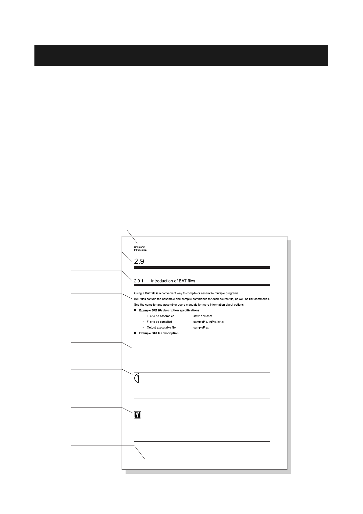
■ This document's format
This manual mainly consists of titles, text, sample programs, precautions, and reference information.
The page layout and definition of these elements are shown below.
Header
The header indicates the
chapter number and title.
Section title
Subsection title
This is the smallest block
used to convey information
in this document.
Te xt
Sample program
Precaution
Reference
information
Footer
The footer indicates
the section title.
Creating executable EX files
c:\panax\cc103\bin\cc103 -c -fenable-asm -103 -O
-Ic:\panax\cc103\include -g int.c
c:\panax\cc103\bin\cc103 -c -fenable-asm -103 -O
-Ic:\panax\cc103\include -g init.c
c:\panax\cc103\bin\cc103 -c -fenable-asm -103 -O
-Ic:\panax\cc103\include -g sample.c
c:\panax\cc103\bin\as103 -g startup.as
c:\panax\cc103\bin\ld103 -g -m -103 -o PWM_output.x -T@DATA=00000000
-T@CODE=40000000 startup.ro int.ro init.ro sample.ro
-l c:\panax\cc103\lib\cc103.l
Please note that the consumption current values provided in this application note are reference
values. Microcomputer power consumption varies largely depending on the nature of the
application (program) as well as the peripheral circuits connected to I/O pins.
For obtaining actual power consumption, please mount the finished device on a product and
measure the power consumption. And then mark it on the face plate and calculate a battery
drive time.
Dual oscillation circuit provides low voltage and low power consumption operation, and highspeed processing.
By selecting between the two oscillation modes according to the current state, power
consumption in standby state can be reduced to as low as 1/330th of that in regular operation,
and data processing can be performed at high speed of up to 4 MHz.
Even at the moment when the oscillation circuit switches modes, all data is preserved, and input
and output are kept stable.
2-72 Creating executable EX files
About This Manual1
Page 5

Format used for sample program explanations
The sample programs included in the Introduction, Microcomputer Basics are explained in the following order of
headings. Unnecessary headings may be omitted depending on their sample program.
• Specification
• Hardware allocation list
• Register description
• Flowchart
• Example program
The following oscillation frequencies this documentís sample programs use: fosc = 10 MHz, fx = 32.768 kHz.
More information
Program CDs and evaluation boards for use with the programs described in this document are available.
Contact your Panasonic sales representative or access the following URL.
http://panasonic.co.jp/semicon/e-micom/inquiry
Evaluation boards are sold through Panasonic sales offices.
About This Manual2
Page 6

About This Manual3
Page 7

..
Table of Contents
Chapter 1 Overview
Chapter 2 Introduction
Chapter 3 Microcomputer Basics 1
Chapter 4 Microcomputer Basics 2
Chapter 5 Appendix
1
2
3
4
5
Page 8

Table of Contents
Chapter 1 Overview
1.1 Overview ................................................................................................................................2
1.2 What is an MN103S92 Series microcomputer .......................................................................3
1.3 MN103S92 Series internal configuration ...............................................................................4
1.4 MN103S92 Series features .....................................................................................................5
1.5 Example application ...............................................................................................................8
1.6 Development language and OS ..............................................................................................9
1.7 Development tools .................................................................................................................9
Chapter 2 Introduction
2.1 Overview ................................................................................................................................2
2.1.1 Overall configuration of sample program ........................................................................3
2.1.2 Sample system specifications and functions to be used ...................................................5
2.1.3 Sample program flowchart overview ...............................................................................6
2.2 Startup ....................................................................................................................................7
2.3 Interrupt functions ................................................................................................................11
2.4 Initial settings of variables ...................................................................................................14
2.5 Initializing functions to be used ...........................................................................................15
2.5.1 CPU operation settings ...................................................................................................16
2.5.2 Motor control PWM operation settings ..........................................................................17
2.5.3 16-bit timer operation .....................................................................................................25
2.5.4 A/D converter operation settings ....................................................................................30
2.5.5 Port settings ....................................................................................................................34
2.5.6 Serial interface operation settings ..................................................................................36
2.5.7 Watchdog timer settings .................................................................................................43
2.6 Interrupt handling .................................................................................................................45
Table of Contents 1
2.6.1 16-bit timer interrupt ......................................................................................................45
2.6.2 Serial interface UART reception interrupt .....................................................................46
Page 9

2.6.3 Serial interface UART transmission interrupt ................................................................48
2.6.4 A/D conversion interrupt ................................................................................................50
2.6.5 Enable multiple interrupts ..............................................................................................52
2.7 Main routine .........................................................................................................................54
2.7.1 A/D conversion processing .............................................................................................55
2.7.2 Serial reception data processing .....................................................................................57
2.7.3 Key input processing ......................................................................................................60
2.7.4 PWM output setting ........................................................................................................62
2.7.5 Switching PWM output phase ........................................................................................68
2.8 Watchdog timer settings .......................................................................................................71
2.8.1 Reset watchdog timer .....................................................................................................71
2.8.2 Watchdog timer overflow processing .............................................................................74
2.9 Creating executable EX files ................................................................................................75
2.9.1 Introduction of BAT files ...............................................................................................75
2.10 System for developing this program ....................................................................................76
2.10.1 Development system configuration ................................................................................76
Chapter 3 Microcomputer Basics 1
3.1 Chapter overview ...................................................................................................................2
3.2 External interrupt ...................................................................................................................3
3.2.1 Setting specification polarity edge interrupts ...................................................................3
3.2.2 Setting both edges interrupts ............................................................................................8
3.2.3 Specification polarity edge interrupt using noise filter ..................................................13
3.2.4 Both edges interrupts using noise filter ..........................................................................20
3.3 I/O ports ...............................................................................................................................27
3.3.1 Setting output port ..........................................................................................................27
3.3.2 Setting input port ............................................................................................................30
3.4 Input-only port .....................................................................................................................33
3.4.1 Setting input-only port ....................................................................................................33
3.5 Pull-up resistor .....................................................................................................................35
3.5.1 Setting pull-up resistor ...................................................................................................35
3.6 8-bit timer operation .............................................................................................................37
Table of Contents 2
Page 10

3.6.1 Counting rising edges using the event count ..................................................................37
3.6.2 Setting timer output pin ..................................................................................................44
3.6.3 50 kHz signal output using the timer output ..................................................................47
3.6.4 Interrupt generation every 100 milli seconds using the cascade connection of
timer 0 and timer 1 .........................................................................................................52
3.6.5 Interrupt generation every 60 seconds using the cascade connection of timer 0,
timer 1, timer 2 and timer 3 ............................................................................................59
3.7 16-bit timer operation ...........................................................................................................68
3.7.1 Counting rising edges using the event count ..................................................................75
3.7.2 Setting timer output pin ..................................................................................................79
3.7.3 50 Hz signal output using the timer output ....................................................................81
3.7.4 1/4 duty waveform output using the timer output ..........................................................85
3.7.5 Pulse width measurement using the timer capture function ...........................................89
3.7.6 Up/down counting selection with TM8AIO (external trigger) .......................................93
3.7.7 Counting operation with 4-fold 2-phase encoding .........................................................97
3.7.8 Count disable with TM8AIO (external trigger) ............................................................103
3.7.9 Timer 1-shot operation .................................................................................................107
3.7.10 Timer activation with TM8AIO (external trigger) .......................................................111
3.8 Synchronous serial interface operation ..............................................................................115
3.8.1 Setting serial transmission pin ......................................................................................115
3.8.2 Setting serial reception pin ...........................................................................................122
3.8.3 Transmitting data with no start condition .....................................................................128
3.8.4 Transmitting and receiving data with no start condition ..............................................137
3.8.5 Receiving data with no start condition .........................................................................146
3.9 A/D conversion function ....................................................................................................154
3.9.1 Setting analog input pin ................................................................................................154
3.9.2 A/D conversion of single channel ................................................................................157
3.9.3 A/D conversion of multiple channels ...........................................................................163
3.9.4 A/D conversion of multiple channels using control register B ....................................171
3.10 Motor control .....................................................................................................................181
3.10.1 Setting motor control PWM output pin ........................................................................187
3.10.2 Saw-tooth wave mode output .......................................................................................189
3.10.3 Deadtime insertion ........................................................................................................193
3.11 Notes for on-board writing to flash memory ......................................................................197
3.11.1 On-board writing using PX-FW2 .................................................................................198
Chapter 4 Microcomputer Basics 2
4.1 Chapter overview ...................................................................................................................2
Table of Contents 3
Page 11

4.2 Writing in/reading from EEPROM using synchronous serial interface .................................3
4.3 120 degrees power on PWM output .....................................................................................22
4.4 Sin wave PWM output using motor control PWM ..............................................................37
Chapter 5 Appendix
5.1 Appendix-1 .............................................................................................................................2
5.2 Appendix-2 .............................................................................................................................3
5.3 Appendix-3 .............................................................................................................................4
Table of Contents 4
Page 12

Table of Contents 5
Page 13

Microcomputer Basics 1
3.6 8-bit timer operation
3.6.1 Counting rising edges using the event count
■ Overview
This program uses Timer 1 to count the rising edges of the external signal input from the TM1IO input pin with a
binary counter.
When the external input signal is detected 5 times, an interrupt is generated and LED connected to P44 flashes.
The setting stored in the base register determines the number of rising edge detections that is counted until an
interrupt is generated.
■ Hardware allocation list
Chapter 3
Source frequency fosc (10 MHz)
Ports used Port 3 (P31) Event input pin
Timers used Timer 1 Event count timer
Count clock source TIM0IO input
Interrupts used Timer 1 interrupt LED connected to P44 flashes
Interrupt level 0
Interrupt source Binary counter underflow
8-bit timer operation III−37
Page 14

Chapter 3
Microcomputer Basics 1
■ Register description
Group 4 Interrupt Control Register (G4ICR: 0x00008910)
bp Flag name Description
15
G4LV2
14-12
G4LV1
G4LV0
11- 10
9G4IE1
8G4IE0
7-6
5G4IR1
4G4IR0
3-2
1G4ID1
0G4ID0
Group 4 interrupt priority level
Set a level from 6 to 0.
Timer 1 underflow interrupt enable flag
0: Disabled
1: Enabled
Timer 0 underflow interrupt enable flag
0: Disabled
1: Enabled
Timer 1 underflow interrupt request flag
0: No interrupt request
1: Interrupt request
Timer 0 underflow interrupt request flag
0: No interrupt request
1: Interrupt request
Timer 1 underflow interrupt detection flag
0: No interrupt detected
1: Interrupt detected
Timer 0 underflow interrupt detection flag
0: No interrupt detected
1: Interrupt detected
Timer 1 Base Register (TM1BR: 0x0000A149)
bp Flag name Description
7
6
5
4
3
2
1
0
III−38 8-bit timer operation
TM1BR7
TM1BR6
TM1BR5
TM1BR4
TM1BR3
TM1BR2
TM1BR1
TM1BR0
Timer 1 Base Register
Page 15

Timer 1 Binary Counter (TM1BC: 0x0000A151)
bp Flag name Description
7
6
5
4
3
2
1
0
TM1BC7
TM1BC6
TM1BC5
TM1BC4
TM1BC3
TM1BC2
TM1BC1
TM1BC0
Timer 1 binary counter
Timer 1 Mode Register (TM1MD: 0x0000A141)
bp Flag name Description
Timer operation enable
7TM1CNE
6TM1LDE
0: Operation disabled
1: Operation enabled
Timer initialization
0: Normal operation
1: Initialization
TM1BR value is loaded into TM1BC.
Timer pulse output 1 is reset to low level.
Microcomputer Basics 1
Chapter 3
5-3
Count source selection
000: IOCLK
001: IOCLK/8
2-0
TM1CK2
TM1CK1
TM1CK0
010: IOCLK/32
011: Cascading with Timer 0
100: Timer 0 underflow
101: Setting not available
110: Timer 2 underflow
111: TM1IO pin input
Port 3 I/O Control Register (P3DIR: 0x0000A023)
bp Flag name Description
7
P36D
P35D
6-0
P34D
P33D
P32D
P31D
P30D
P36 to P30 I/O control
0: Input mode
1: Output mode
8-bit timer operation III−39
Page 16

Chapter 3
Microcomputer Basics 1
Port 3 Output Mode Register (P3MD: 0x0000A033)
bp Flag name Description
7-4
Switching outputs
3 P33M
2 P32M
1 P31M
0 P30M
0: I/O port
1: TM3IO
Switching outputs
0: I/O port
1: TM2IO
Switching outputs
0: I/O port
1: TM1IO
Switching outputs
0: I/O port
1: TM0IO
III−40 8-bit timer operation
Page 17

■ Flowchart
Microcomputer Basics 1
Chapter 3
main ()
Initialize CPU
Set P44 output
Set Timer 1 input pin
Set the base register
Set count clock source
Initialize Timer 1
Select Timer 1 normal operation
Set an interrupt level
Enable the interrupt
Binary counter underflow
int_timer1 ()
Start event
P44 state
Low (LED off)
High output (LED on)
END
High (LED on)
Low output (LED off)
8-bit timer operation III−41
Page 18

Chapter 3
Microcomputer Basics 1
■ Example program
/************************************************************************/
/* CHECK Program for The count of the rising edge */
/* which used event count operation(8-bit) */
/************************************************************************/
/* Setting of Main Peripheral */
/* Port 0 : Unused */
/* Port 1 : Unused */
/* Port 2 : Unused */
/* Port 3 : Used as Timer 1 input */
/* Port 4 : Used as output port */
/* Port 5 : Unused */
/* Port 6 : Unused */
/* Port 7 : Unused */
/* Port 8 : Unused */
/* Timer 0 : Unused */
/* Timer 1 : Used as Event count operation */
/* Timer 2 : Unused */
/* Timer 3 : Unused */
/* Timer 8 : Unused */
/* Timer 11 : Unused */
/* 3-phase PWM output : Unused */
/* Serial interface communication 2 : Unused */
/* 10-bit A/D converters : Unused */
/* */
/* Interrupt : External interrupt Unused */
/* */
/* 2004/09 Rev 0.1 */
/************************************************************************/
#include "sr103s92.h"
#include "int.h"
/****************************/
/* Declaration of function */
/****************************/
void main(void);
void initialize(void);
/*---------------------------------------------- After the assembler boot processing is completed
control is shifted to this main routine.
-----------------------------------------------*/
void main(void)
{
initialize(); /* Initial Job */
TM1MD = 0x00; /* Stop the counter */
/*---------------------------------------------- P4 setting
-----------------------------------------------*/
P4OUT = 0x00; /* Set P44 Low(VSS level) */
P4DIR = 0x10; /* Set P44 output */
/*---------------------------------------------- P3 setting
-----------------------------------------------*/
P3MD = 0x02; /* Set TM1IO port */
P3DIR = 0x00; /* Set P31 input */
/*---------------------------------------------- Event count timer setting
-----------------------------------------------*/
TM1BR = 0x04; /* Set the base register */
TM1MD = TM1MD | 0x07; /* Select the clock source to TMIN1 pin input */
TM1MD = TM1MD | 0x40; /* Initial timer */
TM1MD = TM1MD & 0xBF; /* Set normal operation */
G4ICR = 0x0200; /* Set an interrupt level */
/* Enable the interrupt */
asm (" or 0x0F00,PSW\n"); /* Enable the interrupt, Interrupt level 7 */
III−42 8-bit timer operation
Page 19

asm (" nop\n");
asm (" nop\n");
TM1MD = TM1MD | 0x80; /* Start the counter */
while(1){
}
}
/*--------------------------------------------- Operation initial setting
----------------------------------------------*/
void initialize(void)
{
asm (" and 0xF0FF,PSW\n"); /* Disable all maskable interrupts */
asm (" nop\n");
asm (" nop\n");
CPUM = 0x0000; /* Set normal mode */
}
/*---------------------------------------------- Timer 1 underflow
-----------------------------------------------*/
void int_timer1(void)
{
if(P4OUT & 0x10){
P4OUT = 0x00; /* Set P44 Low(VSS level) */
}
else{
P4OUT = 0x10; /* Set P44 High(VDD level) */
}
}
Microcomputer Basics 1
Chapter 3
8-bit timer operation III−43
Page 20

Inquiries
If you have questions regarding technical information on this manual, please visit the following
URL.
User Support Team
Semiconductor Company
Matsushita Electric Industrial Co., Ltd.
URL: http://panasonic.co.jp/semicon/e-micom/inquiry
For inquiries regarding Microcomputer,
• Microcomputer Web site
We offer you technical information regarding microcomputers at http://panasonic.co.jp/semicon/e-micom.
• Microcomputer Manual Download Site
http://panasonic.co.jp/semicon/e-micom/manual
We upload LSI User’s Manuals and Tool Manuals in PDF format at URL above.
• For inquiries on microcomputer technical information
http://panasonic.co.jp/semicon/e-micom/inquiry
We inform you of an e-mail address for inquires per LSI model at URL above.
Please send your inquires according to your microcomputer model.
MN103S927/92A/F92G
LSI Application Notes Excerption
March, 2005 1st Edition
Issued by Matsushita Electric Industrial Co., Ltd.
2005 Matsushita Electric Industrial Co., Ltd. All Rights Reserved
Page 21

SALES OFFICES
NORTH AMERICA
U.S.A. Sales Office:
Panasonic Industrial Company [PIC]
New Jersey Office:
2 Panasonic Way Secaucus, New Jersey 07094, U.S.A.
Chicago Office:
1707 N. Randall Road Elgin, Illinois 60123-7847, U.S.A.
San Jose Office:
2033 Gateway Place, Suite 200, San Jose, California 95110,
U.S.A
Atlanta Office:
1225 Northbrook Parkway Suite 1-151 Suwanee, Georgia 30024,
U.S.A.
San Diego Office:
9444 Balboa Avenue, Suite 185, San Diego, California 92123,
U.S.A.
Tel:1-858-503-2910 Fax:1-858-715-5545
Panasonic Canada Inc. [PCI]
5770 Ambler Drive 27 Mississauga, Ontario L4W 2T3, Canada
Tel:1-201-348-5257 Fax:1-201-392-4652
Tel:1-847-468-5720 Fax:1-847-468-5725
Tel:1-408-487-9510 Fax:1-408-436-8037
Tel:1-770-338-6953 Fax:1-770-338-6849
Canada Sales Office:
Tel:1-905-238-2243 Fax:1-905-238-2414
LATIN AMERICA
Mexico Sales Office:
Panasonic de Mexico, S.A. de C.V. [PANAMEX]
Amores 1120 Col. Del Valle Delegacion Benito Juarez C.P. 03100
Mexico, D.F. Mexico
Guadalajara Office:
Sucursal Guadarajara Av. Lazaro Cardenas 2305 Local G-102
Plaza Comercial Abastos; Col. Las Torres Guadalajara, Jal.
44920, Mexico
Brazil Sales Office:
Panasonic do Brasil Ltda. [
Caixa Postal 1641, Sao Jose dos Campos, Estado de Sao Paulo,
Brasil
Tel:52-5-488-1000 Fax:52-5-488-1073
Tel:52-3-671-1205 Fax:52-3-671-1256
PANABRAS]
Tel:55-12-3935-9000 Fax:55-12-3931-3789
EUROPE
Europe Sales Office:
Panasonic Industrial Europe GmbH [PIE]
Germany Sales Office:
Hans-Pinsel-Strasse 2 85540 Haar, Germany
Tel:49-89-46159-119 Fax:49-89-46159-195
ASIA
Singapore Sales Office:
Panasonic Semiconductor Sales Asia [PSCSA]
300 Beach Road, #16-01, the Concourse, Singapore 199555, the
Republic of Singapore
Malaysia Sales Office:
Panasonic Industrial Company (M) Sdn. Bhd. [PICM]
Head Office:
15th Floor, Menara IGB, Mid Valley City, Lingkaran Syed
Putra, 59200 Kuala Lumpur, Malaysia
Penang Office:
Suite 20-07,20th Floor, MWE Plaza, No.8, Lebuh Farquhar,10200
Penang, Malaysia
Johore Sales Office:
Menara Pelangi, Suite8.3A, Level8, No.2, Jalan Kuning, Taman
Pelangi, 80400 Johor Bahru, Johor, Malaysia
Thailand Sales Office:
Panasonic Industrial (Thailand) Ltd. [PICT]
252-133 Muang Thai-Phatra Complex Building, 31st Floor
Rachadaphisek Road, Huaykwang, Bangkok 10320, Thailand
Philippines Sales Office:
Panasonic Industrial Sales Philippines [PISP]
102 Laguna Boulevard,Bo.Don Jose Laguna Technopark, Santa.
Rosa, Laguna 4026, the Philippines
China Sales Office:
Panasonic Semiconductor Sales (China) [PSCSCH]
Panasonic Industrial (China) Co., Ltd.
Semiconductor Group
Floor 12, China Insurance Building, 166 East Road
Lujiazui, Pudong New District, Shanghai 200120, China
Panasonic Industrial (Tianjin) Co., Ltd.
Semiconductor Group
Room No.1001, Tianjin International Building, 75 Nanjing Road,
Tianjin 300050, China
Panasonic SH Industrial Sales (Shenzhen) Co., Ltd.
Semiconductor Group (Shum Yip Centre Office)
25F, Shum Yip Centre, #5045, East Shennan Road, Shenzhen
518010, China
Panasonic Shun Hing Industrial Sales (Hong Kong) Co., Ltd.
Semiconductor Group
11th Floor, Great Eagle Centre, 23 Harbour Road, Wanchai, Hong Kong
Taiwan Sales Office:
Panasonic Industrial Sales (Taiwan) Co.,Ltd. [PIST]
Head Office:
6F, 550, Sec. 4, Chung Hsiao E. RD. Taipei 110, Taiwan
Kaohsiung Office:
6th Floor, Hsin Kong Bldg. No.251, Chi Hsien 1st Road,
Kaohsiung 800, Taiwan
Korea Sales Office:
Panasonic Industrial Korea Co., Ltd. [PIKL]
Kukje Center Bldg. 11th Floor, 191 Hangangro 2ga, Youngsan-ku,
Seoul 140-702, Korea
Tel:65-6390-3688 Fax:65-6390-3689
Tel:60-3-2297-6888 Fax:60-6-2284-6898
Tel: 60-4-201-5113 Fax:60-4-261-9989
Tel:60-7-331-3822 Fax:60-7-355-3996
Tel:66-2-693-3400 to 3421 Fax:66-2-693-3422 to 3427
Tel:63-2-520-8615 Fax:63-2-520-8629
Tel:86-21-6841-9642 Fax:86-21-6841-9631
Tel:86-22-2313-9771 Fax:86-22-2313-9770
Tel:86-755-8211-0888 Fax:86-755-8211-0970
Tel:852-2529-7322 Fax:852-2865-4455
Tel:886-2-2757-1900 Fax:886-2-2757-1906
Tel:886-7-346-3815 Fax:886-7-236-8362
Tel:82-2-795-9600 Fax:82-2-795-1542
Semiconductor Company, Matsushita Electric Industrial Co., Ltd.
Nagaokakyo, Kyoto 617-8520, Japan
Tel:075-951-8151
070305 Printed in Japan
http://panasonic.co.jp/semicon/e-index.html
 Loading...