

Panasonic MINAS S Operating Manual
AC Servo Motor Driver
MINAS S-series
Operating Manual
WWW.100Y.COM.TW WWW.100Y.COM.TW WWW.100Y.COM.TW
WWW.100Y.COM.TW WWW.100Y.COM.TW WWW.100Y.COM.TW
WWW.100Y.COM.TW WWW.100Y.COM.TW WWW.100Y.COM.TW
WWW.100Y.COM.TW WWW.100Y.COM.TW WWW.100Y.COM.TW
WWW.100Y.COM.TW WWW.100Y.COM.TW WWW.100Y.COM.TW
WWW.100Y.COM.TW WWW.100Y.COM.TW WWW.100Y.COM.TW
WWW.100Y.COM.TW WWW.100Y.COM.TW WWW.100Y.COM.TW
WWW.100Y.COM.TW WWW.100Y.COM.TW WWW.100Y.COM.TW
Be sure give this instruction manual to the user.
WWW.100Y.COM.TW WWW.100Y.COM.TW WWW.100Y.COM.TW
WWW.100Y.COM.TW WWW.100Y.COM.TW WWW.100Y.COM.TW
• Thank you very much for your buying Panasonic AC Servo Motor Driver,A-series.
WWW.100Y.COM.TW WWW.100Y.COM.TW WWW.100Y.COM.TW
• Before use, read through this manual to ensure proper use. Keep this manual at an easily
WWW.100Y.COM.TW WWW.100Y.COM.TW WWW.100Y.COM.TW
accessible place so as to be referred anytime as necessary.
WWW.100Y.COM.TW WWW.100Y.COM.TW WWW.100Y.COM.TW
WWW.100Y.COM.TW WWW.100Y.COM.TW WWW.100Y.COM.TW

Table of Contents
Before Use
Safety Precautions
•••••4
Introduction •••••••••••••8
After Opening the Package•••••••••••••••• 8
Check the Model Number of Amplifier ••••••••••••••••••
Check the Model Number of Motor •••••••••••••••••••
Check the Combination of Amplifier and Motor •••••••••••••••••••••
8
9
10
Parts Description
Amplifier ••••••••••••••••••••••••••••••••••••• 12
Motor ••••••••••••••••••••••••••••••••••••••••• 13
Installation •••••••••••••••••14
Amplifier ••••••••••••••••••••••••••••••••••••• 14
Motor ••••••••••••••••••••••••••••••••••••••••• 16
•••••••••••12
Preparations
and Adjustments
System Configuration and Wiring •••••
General Wiring Diagram
List of Available Components
Main Circuits ••••••••••••••••••••••••••••••• 22
WWW.100Y.COM.TW WWW.100Y.COM.TW WWW.100Y.COM.TW
CN SIG Connector
WWW.100Y.COM.TW WWW.100Y.COM.TW WWW.100Y.COM.TW
For Encoder ••••••••••••••••••••••••••••• 23
CN SER Connector ••••••••••••••••••••••• 24
WWW.100Y.COM.TW WWW.100Y.COM.TW WWW.100Y.COM.TW
CN I/F Connector
WWW.100Y.COM.TW WWW.100Y.COM.TW WWW.100Y.COM.TW
For Controller •••••••••••••••••••••••••••• 25
WWW.100Y.COM.TW WWW.100Y.COM.TW WWW.100Y.COM.TW
CN MON Connector ••••••••••••••••••• 35
WWW.100Y.COM.TW WWW.100Y.COM.TW WWW.100Y.COM.TW
Parameter Setting
WWW.100Y.COM.TW WWW.100Y.COM.TW WWW.100Y.COM.TW
Overview •••••••••••••••••••••••••••••••••••• 36
Parameter Groups and Listing
WWW.100Y.COM.TW WWW.100Y.COM.TW WWW.100Y.COM.TW
Setting the Parameters ••••••••••••••••••• 41
WWW.100Y.COM.TW WWW.100Y.COM.TW WWW.100Y.COM.TW
Overview of PANATERM
WWW.100Y.COM.TW WWW.100Y.COM.TW WWW.100Y.COM.TW
How to Connect•••••••••••••••••••••••••••• 41
••••••••••••••••••••••• 18
•••••••••••••••••• 20
•••••••••••36
••••••••••••••• 36
••••••••••••••• 41
“
18
WWW.100Y.COM.TW WWW.100Y.COM.TW WWW.100Y.COM.TW
WWW.100Y.COM.TW WWW.100Y.COM.TW WWW.100Y.COM.TW
WWW.100Y.COM.TW WWW.100Y.COM.TW WWW.100Y.COM.TW
WWW.100Y.COM.TW WWW.100Y.COM.TW WWW.100Y.COM.TW
Trial Run •••••••••••••••••••44
Inspections before Trial Run
Operation with
CN I/F Connected •••••••••••••••••• 45
••••••••••••••••••• 44
Adjustments•••••••••••••••50
Purposes of Gain Adjustments
Types of Gain Adjustments •••••••••••••• 50
How to Adjust Gain •••••••••••••••••••••••• 52
How to Use
"Normal Auto-Gain" Tuning
How to Use "Real Time
Auto-Gain" Tuning •••••••••••••••• 54
How to Adjust Gain Manually
Gain Tuning Using
Gain Adjustment Rotary Switch
To reduce the mechanincal
resonance
- 2 -
••••••••••••••••••••••••••• 59
••••••••••••••• 50
••••••••••••••• 55
•••••••••• 53
••••••••• 58

Important Information
Protective Functions •••••••••••
60
Maintenance and
Inspections ••••••••••• 6 6
Troubleshooting
••••••••••••••••••••••••••••••68
After-Sale Service
•••••••••••••••••••••• Back cover
Appendixes
Conformance to EC Directives and UL Standards
Holding Brake ••••••••••••••••••••••••• App. 6
Dynamic Brake•••••••••••••••••••••••• App. 8
Timing Chart ••••••••••••••••••••••••• App. 10
Acceptable Loads on Output Shaft •••••••••••••••
Homing Operation (Precautions) ••••••••••••••
WWW.100Y.COM.TW WWW.100Y.COM.TW WWW.100Y.COM.TW
WWW.100Y.COM.TW WWW.100Y.COM.TW WWW.100Y.COM.TW
WWW.100Y.COM.TW WWW.100Y.COM.TW WWW.100Y.COM.TW
WWW.100Y.COM.TW WWW.100Y.COM.TW WWW.100Y.COM.TW
WWW.100Y.COM.TW WWW.100Y.COM.TW WWW.100Y.COM.TW
WWW.100Y.COM.TW WWW.100Y.COM.TW WWW.100Y.COM.TW
WWW.100Y.COM.TW WWW.100Y.COM.TW WWW.100Y.COM.TW
WWW.100Y.COM.TW WWW.100Y.COM.TW WWW.100Y.COM.TW
WWW.100Y.COM.TW WWW.100Y.COM.TW WWW.100Y.COM.TW
WWW.100Y.COM.TW WWW.100Y.COM.TW WWW.100Y.COM.TW
WWW.100Y.COM.TW WWW.100Y.COM.TW WWW.100Y.COM.TW
WWW.100Y.COM.TW WWW.100Y.COM.TW WWW.100Y.COM.TW
WWW.100Y.COM.TW WWW.100Y.COM.TW WWW.100Y.COM.TW
WWW.100Y.COM.TW WWW.100Y.COM.TW WWW.100Y.COM.TW
••••••••••• App. 2
App. 14
App. 15
Details of Parameters ••••••••••••• App. 16
Optional Parts ••••••••••••••••••••••• App. 38
Recommended Parts •••••••••••••• App. 47
Dimensions •••••••••••••••••••••••••• App. 48
Characteristics •••••••••••••••••••••• App. 53
Specifications ••••••••••••••••••••••• App. 54
- 3 -
Safety Precautions
Observe the following precautions in order to avoid injuries of operators and other persons, and mechanical damages.
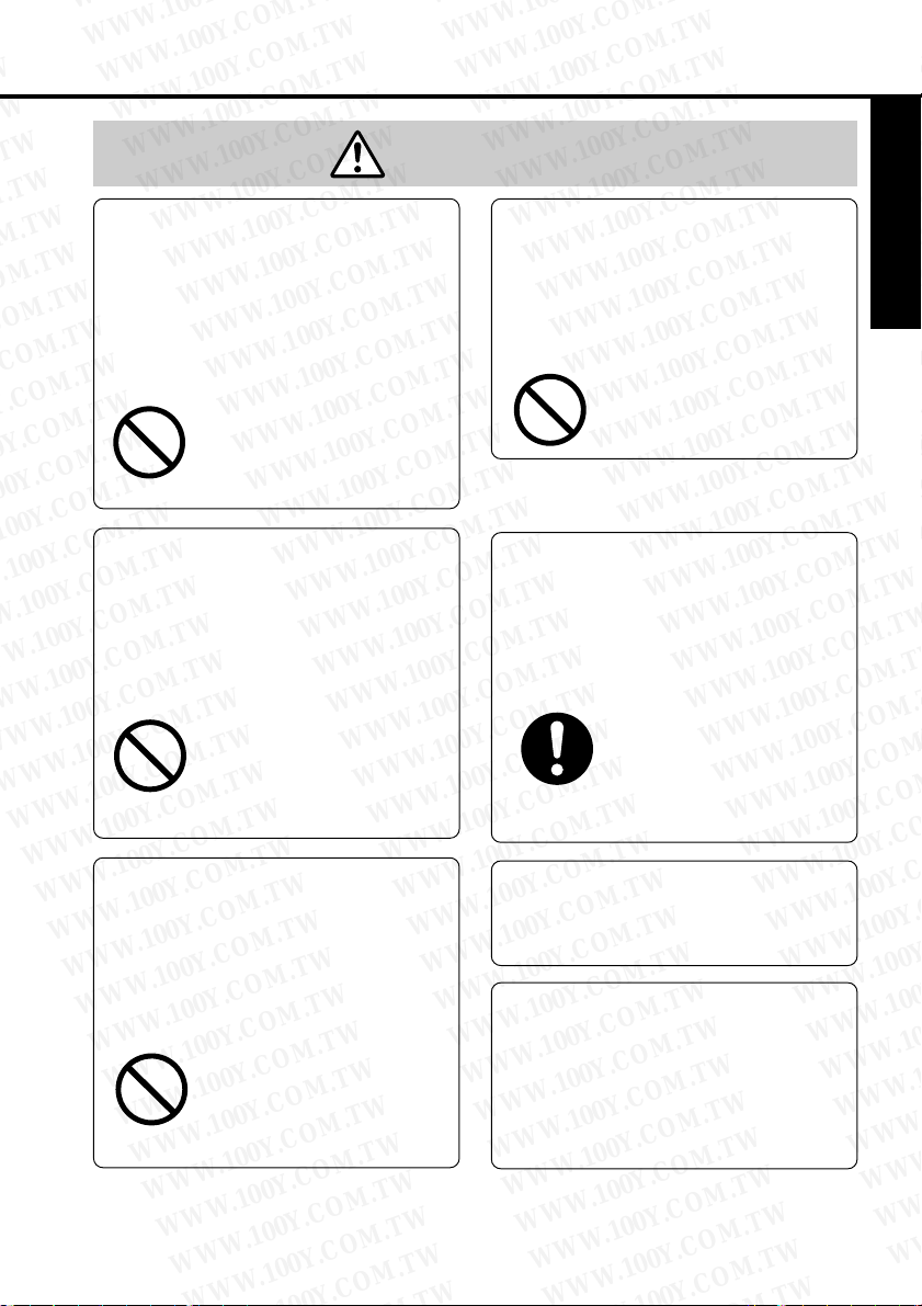
The following DANGER and CAUTION symbols are used according to the level of dangers possibly occur-
ring if you fail to observe the instructions or precautions indicated.
(Important)
DANGER
CAUTION
The following symbols indicate what you are not allowed to do, or what you
must observe.
Indicates a potentially hazardous situation which, if not
avoided, will result in death or serious injury.
Indicates a potentially hazardous situation which, if not avoided,
will result in minor or moderate injury and physical damage.
This symbol indicates that the operation is prohibited.
This symbol indicates that the operation must
be performed without fail.
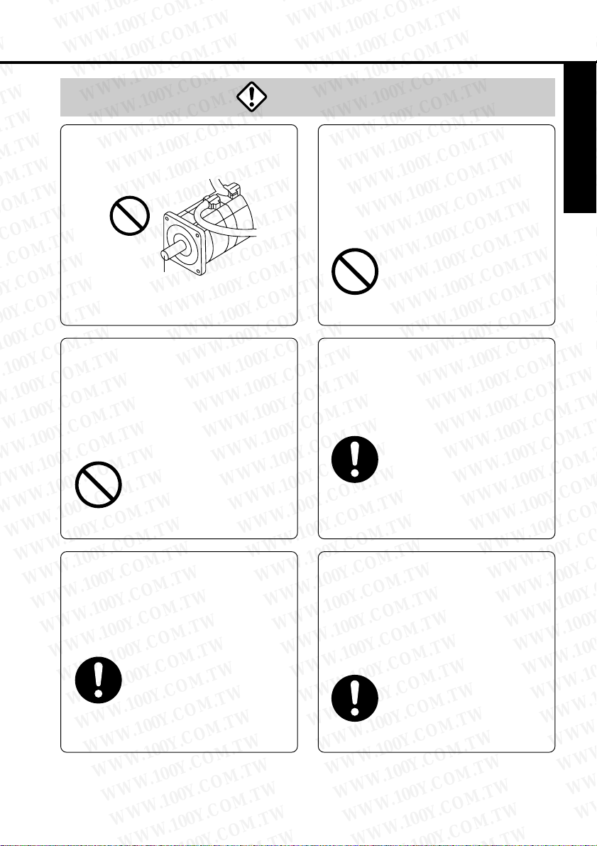
DANGER
WWW.100Y.COM.TW WWW.100Y.COM.TW WWW.100Y.COM.TW
An over-current protection, earth leakage
breaker, over-temperature protection and
WWW.100Y.COM.TW WWW.100Y.COM.TW WWW.100Y.COM.TW
emergency stop should be installed.
WWW.100Y.COM.TW WWW.100Y.COM.TW WWW.100Y.COM.TW
WWW.100Y.COM.TW WWW.100Y.COM.TW WWW.100Y.COM.TW
WWW.100Y.COM.TW WWW.100Y.COM.TW WWW.100Y.COM.TW
Failure to observe this
instruction could result in electric
shocks, injuries and/or fire.
Don't insert your hands in
the amplifier.
Failure to observe this
instruction could result in
burns and/or electric shocks.
WWW.100Y.COM.TW WWW.100Y.COM.TW WWW.100Y.COM.TW
Install the amplifier securely to pre-
WWW.100Y.COM.TW WWW.100Y.COM.TW WWW.100Y.COM.TW
vent fire hazard and personal injury
WWW.100Y.COM.TW WWW.100Y.COM.TW WWW.100Y.COM.TW
resulting from earthquake.
WWW.100Y.COM.TW WWW.100Y.COM.TW WWW.100Y.COM.TW
Failure to observe this
instruction could result in electric
WWW.100Y.COM.TW WWW.100Y.COM.TW WWW.100Y.COM.TW
shocks, injuries and/or fire.
Be sure to check safety
after occurrence of earthquake.
Failure to observe this
instruction could result in electric
shocks, injuries and/or fire.
WWW.100Y.COM.TW WWW.100Y.COM.TW WWW.100Y.COM.TW
WWW.100Y.COM.TW WWW.100Y.COM.TW WWW.100Y.COM.TW
WWW.100Y.COM.TW WWW.100Y.COM.TW WWW.100Y.COM.TW
WWW.100Y.COM.TW WWW.100Y.COM.TW WWW.100Y.COM.TW
-4-
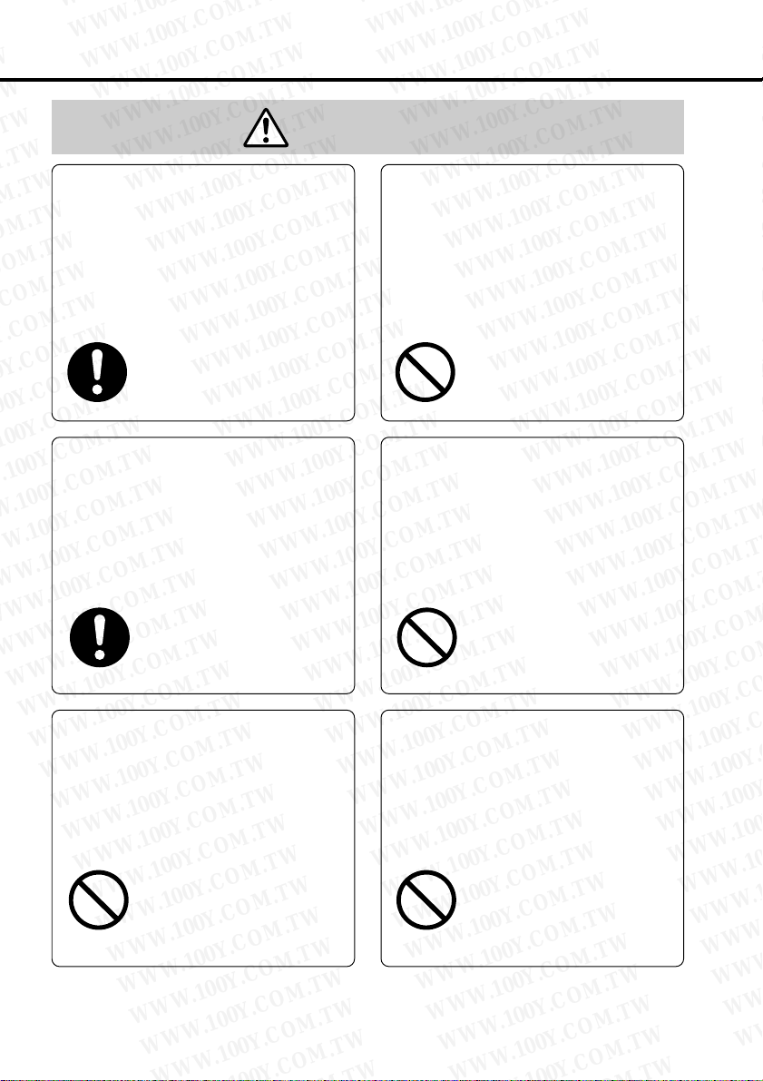
DANGER
Before Use
Don't touch the rotating
part of the motor in motion.
Don't subject the product to
water splash, corrosive
gases, flammable gases and
combustible things.
Failure to observe this in-
Rotating part
Failure to observe this instruction could
result in injuries.
Do not expose the cables to
sharp edges, excessive
pressing forces, heavy
loads or pinching forces.
Failure to observe this
instruction could result in
electric shocks,
WWW.100Y.COM.TW WWW.100Y.COM.TW WWW.100Y.COM.TW
malfunction and/or
damages.
Perform the transportation,
wiring and inspection at
least 10 minutes after the
power off.
Always ask to an electrical engineer for wiring.
struction could result in
fire.
Failure to observe this instruction could result in
electric shocks.
WWW.100Y.COM.TW WWW.100Y.COM.TW WWW.100Y.COM.TW
WWW.100Y.COM.TW WWW.100Y.COM.TW WWW.100Y.COM.TW
WWW.100Y.COM.TW WWW.100Y.COM.TW WWW.100Y.COM.TW
of the amplifier.
WWW.100Y.COM.TW WWW.100Y.COM.TW WWW.100Y.COM.TW
WWW.100Y.COM.TW WWW.100Y.COM.TW WWW.100Y.COM.TW
Ground the earth terminal
WWW.100Y.COM.TW WWW.100Y.COM.TW WWW.100Y.COM.TW
WWW.100Y.COM.TW WWW.100Y.COM.TW WWW.100Y.COM.TW
WWW.100Y.COM.TW WWW.100Y.COM.TW WWW.100Y.COM.TW
Failure to observe this
instruction could result in
electric shocks.
WWW.100Y.COM.TW WWW.100Y.COM.TW WWW.100Y.COM.TW
Install an external
emergency stop device so
that you can shut off the
power in any emergency
cases.
Failure to observe this
instruction could result in
injuries, electric shocks, fire,
malfunction and/or mechanical
damages.
WWW.100Y.COM.TW WWW.100Y.COM.TW WWW.100Y.COM.TW
WWW.100Y.COM.TW WWW.100Y.COM.TW WWW.100Y.COM.TW
WWW.100Y.COM.TW WWW.100Y.COM.TW WWW.100Y.COM.TW
WWW.100Y.COM.TW WWW.100Y.COM.TW WWW.100Y.COM.TW
-5-
Safety Precautions
Caution
(Important)
Use the motor and
amplifier in the specified
combination.
Failure to observe this instruction could result in fire.
If an error occurs,
remove the causes for
the error and secure the
safety before restarting
the operation.
Failure to observe this
WWW.100Y.COM.TW WWW.100Y.COM.TW WWW.100Y.COM.TW
instruction could result in
injuries.
Execute the trial operations
with the motor fixed but
without motor load connected.
Connecting a load to the
motor is possible only after
successful trial operation.
Failure to observe this instruction could result in injuries.
Don't touch the motor,
amplifier or its
regenerative discharge
resistor, since they
become hot.
Failure to observe this
instruction could result in
burns.
WWW.100Y.COM.TW WWW.100Y.COM.TW WWW.100Y.COM.TW
WWW.100Y.COM.TW WWW.100Y.COM.TW WWW.100Y.COM.TW
Avoid extreme
WWW.100Y.COM.TW WWW.100Y.COM.TW WWW.100Y.COM.TW
adjustment or change.
WWW.100Y.COM.TW WWW.100Y.COM.TW WWW.100Y.COM.TW
Avoid an operation
WWW.100Y.COM.TW WWW.100Y.COM.TW WWW.100Y.COM.TW
which causes unstable
WWW.100Y.COM.TW WWW.100Y.COM.TW WWW.100Y.COM.TW
action.
WWW.100Y.COM.TW WWW.100Y.COM.TW WWW.100Y.COM.TW
Failure to observe this
WWW.100Y.COM.TW WWW.100Y.COM.TW WWW.100Y.COM.TW
instruction could result in
injuries.
WWW.100Y.COM.TW WWW.100Y.COM.TW WWW.100Y.COM.TW
Don't modify, dismantle
or repair the amplifier.
Failure to observe this instruction could result in fire,
electric shocks and/or injuries.
WWW.100Y.COM.TW WWW.100Y.COM.TW WWW.100Y.COM.TW
WWW.100Y.COM.TW WWW.100Y.COM.TW WWW.100Y.COM.TW
WWW.100Y.COM.TW WWW.100Y.COM.TW WWW.100Y.COM.TW
WWW.100Y.COM.TW WWW.100Y.COM.TW WWW.100Y.COM.TW
-6-
Caution
Before Use
Don't hold the cables or
motor shaft when
transporting the motor.
After recovery from the
power failure, the
equipment may restart
suddenly. Don't approach
the equipment
Failure to observe this
Failure to observe this
instruction could result
in injuries.
Don't block the heat
dissipation hole or insert
*Provide appropriate settings as a preparedness against
the accidental restart of the machine in order to ensure
the safety of personnel.
Observe the voltage
specified.
instruction could result in
injuries.
foreign matters in it.
Failure to observe this
instruction could result
in electric shocks,
WWW.100Y.COM.TW WWW.100Y.COM.TW WWW.100Y.COM.TW
injuries and/or fire.
Failure to observe this
instruction could result in
electric shocks,
injuries and/or fire.
WWW.100Y.COM.TW WWW.100Y.COM.TW WWW.100Y.COM.TW
WWW.100Y.COM.TW WWW.100Y.COM.TW WWW.100Y.COM.TW
WWW.100Y.COM.TW WWW.100Y.COM.TW WWW.100Y.COM.TW
Make sure that the
wirings are made
WWW.100Y.COM.TW WWW.100Y.COM.TW WWW.100Y.COM.TW
correctly.
This equipment should be
treated as an industrial
waste when it is disposed of.
WWW.100Y.COM.TW WWW.100Y.COM.TW WWW.100Y.COM.TW
WWW.100Y.COM.TW WWW.100Y.COM.TW WWW.100Y.COM.TW
WWW.100Y.COM.TW WWW.100Y.COM.TW WWW.100Y.COM.TW
WWW.100Y.COM.TW WWW.100Y.COM.TW WWW.100Y.COM.TW
WWW.100Y.COM.TW WWW.100Y.COM.TW WWW.100Y.COM.TW
Failure to observe this
instruction could result in
electric shocks, injuries.
WWW.100Y.COM.TW WWW.100Y.COM.TW WWW.100Y.COM.TW
Do not turn on/off the
main power frequently.
Failure to observe this
instruction could result
in malfunctions.
WWW.100Y.COM.TW WWW.100Y.COM.TW WWW.100Y.COM.TW
WWW.100Y.COM.TW WWW.100Y.COM.TW WWW.100Y.COM.TW
WWW.100Y.COM.TW WWW.100Y.COM.TW WWW.100Y.COM.TW
-7-
Introduction
After Opening the Package
• Make sure that the product is what you have ordered.
•
Check whether the product has been damaged or not during transportation.
If the product is not correct, or it has been damaged, contact dealer or sales agent.
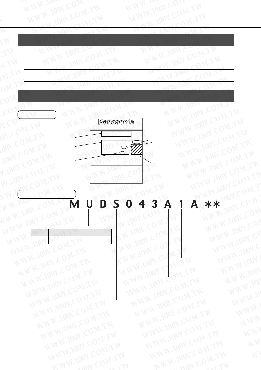
Check the Model of Amplifier
Name plate
Model
Rated input voltage
Rated motor output
AC SERVO DRIVER
MUDS3A1A1A
Model No.
INPUT OUTPUT ENCODER
Voltage
100-115V 32V
1ø 3ø
Phase
1.0A 1.0A
F.L .C
Freq.
50/60Hz 0~333.3Hz
Power
60/75 Wire Only
Use Copper Conductors Only
Refer to Manual for Wiring and Wire Size
Refer to Manual for Over Load Protection
30W
SER.NO.
00010001
Number of pulses of the
encoder(resolution)
2500P/R
Rated output current
Serial Number
Model Designation
1~3 5~6
478910
11~12
WWW.100Y.COM.TW WWW.100Y.COM.TW WWW.100Y.COM.TW
Symbol
WWW.100Y.COM.TW WWW.100Y.COM.TW WWW.100Y.COM.TW
WWW.100Y.COM.TW WWW.100Y.COM.TW WWW.100Y.COM.TW
WWW.100Y.COM.TW WWW.100Y.COM.TW WWW.100Y.COM.TW
WWW.100Y.COM.TW WWW.100Y.COM.TW WWW.100Y.COM.TW
WWW.100Y.COM.TW WWW.100Y.COM.TW WWW.100Y.COM.TW
WWW.100Y.COM.TW WWW.100Y.COM.TW WWW.100Y.COM.TW
WWW.100Y.COM.TW WWW.100Y.COM.TW WWW.100Y.COM.TW
WWW.100Y.COM.TW WWW.100Y.COM.TW WWW.100Y.COM.TW
Applicable motors
MUD
WWW.100Y.COM.TW WWW.100Y.COM.TW WWW.100Y.COM.TW
WWW.100Y.COM.TW WWW.100Y.COM.TW WWW.100Y.COM.TW
WWW.100Y.COM.TW WWW.100Y.COM.TW WWW.100Y.COM.TW
MUMÅi
Extra low inertia
Åj
Series symbol
S: S-series
Custom specification 1 (1,
2, 3...)
1: Standard
Rotary encoder
(see Table 1-b)
Power supply
1: Single-phase, 100V
2: Single-phase, 200V
3: Three-phase, 200V
5: Three-phase/Single-phase, 200V
(common phase)
Rated motor output (see
Table 1-a)
Custom
specification
Custom specification 2
(A, B, C...)
A: Standard
WWW.100Y.COM.TW WWW.100Y.COM.TW WWW.100Y.COM.TW
WWW.100Y.COM.TW WWW.100Y.COM.TW WWW.100Y.COM.TW
-8-
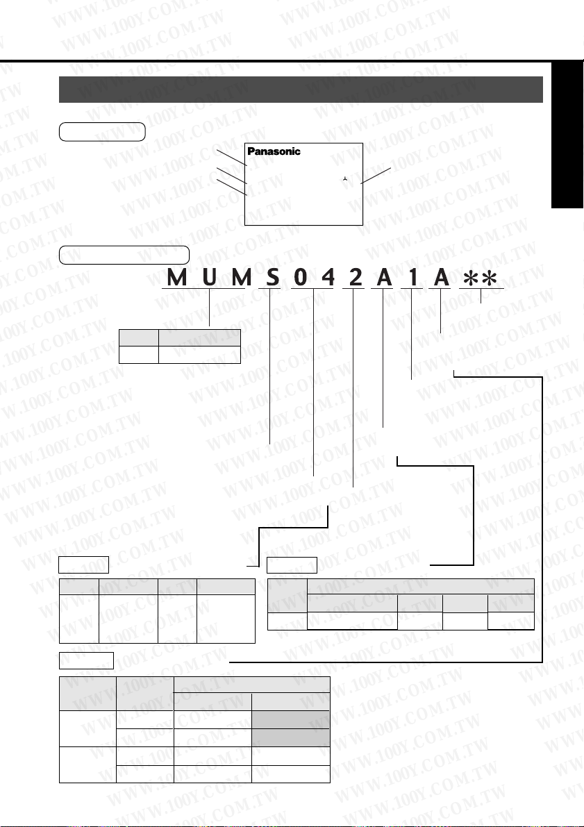
Check the Model of Motor
Name plate
Type
Rated output
Revolution rating
Model Designation
AC SERVO MOTOR
Model No.
MUMS042A1A
INPUT 3ØAC
RATED OUTPUT
RATED FREQ.
200
RATED REV.
3000
92
V
A1.6
kW
0.2
Hz
r/min
0.64
CONT. TORQUE
RATING S1
INS. CLASS B (TÜV) A (UL)
IP65
CONNECTION
SER No.
00010001
MatsushitaElectric Industrial Co..Ltd.
Made in Japan
Before Use
Nm
Serial No
1~3 5~6
Symbol
MUM
Type
Super low inertia
WWW.100Y.COM.TW WWW.100Y.COM.TW WWW.100Y.COM.TW
WWW.100Y.COM.TW WWW.100Y.COM.TW WWW.100Y.COM.TW
WWW.100Y.COM.TW WWW.100Y.COM.TW WWW.100Y.COM.TW
Table 1-a
WWW.100Y.COM.TW WWW.100Y.COM.TW WWW.100Y.COM.TW
Symbol
WWW.100Y.COM.TW WWW.100Y.COM.TW WWW.100Y.COM.TW
3A
WWW.100Y.COM.TW WWW.100Y.COM.TW WWW.100Y.COM.TW
5A
01
WWW.100Y.COM.TW WWW.100Y.COM.TW WWW.100Y.COM.TW
Table 1-c
WWW.100Y.COM.TW WWW.100Y.COM.TW WWW.100Y.COM.TW
WWW.100Y.COM.TW WWW.100Y.COM.TW WWW.100Y.COM.TW
Oil seal
WWW.100Y.COM.TW WWW.100Y.COM.TW WWW.100Y.COM.TW
None
Rated Motor Output
Rated output
30W
50W
100W
Symbol
02
04
08
Rated output
200W
400W
750W
Motor Structure
Brake
None
WWW.100Y.COM.TW WWW.100Y.COM.TW WWW.100Y.COM.TW
Yes
Yes
None
WWW.100Y.COM.TW WWW.100Y.COM.TW WWW.100Y.COM.TW
Yes
WWW.100Y.COM.TW WWW.100Y.COM.TW WWW.100Y.COM.TW
Straight
A
B
C
D
WWW.100Y.COM.TW WWW.100Y.COM.TW WWW.100Y.COM.TW
478910
Custom specification 1
1: Standard
Rotary encoder
Series symbol
S: S-series
Rated output
(see Table 1-a)
Table 1-b
Symbol
A
Shaft
Key way
Rotary Encoder
Type
Incremental
(see Table 1-b)
Voltage
1: 100V
2: 200V
Z: 100/200V
Specifications
No. of pulses
2500P/r
∑ Specifications with the shaft
provided with key way are standard.
11~12
Custom specification 2
Motor structure
(see Table 1-c)
Resolution
10000
E
F
G
H
-9-
Lead wire
11- wire

Introduction
Check the Combination of Amplifier and Motor
The amplifier has been designed for use in combination with the specified motors only.
Check the specifications (Series symbol, output rating, voltage rating and encoder type) of
the motor you want to use.
WWW.100Y.COM.TW WWW.100Y.COM.TW WWW.100Y.COM.TW
WWW.100Y.COM.TW WWW.100Y.COM.TW WWW.100Y.COM.TW
WWW.100Y.COM.TW WWW.100Y.COM.TW WWW.100Y.COM.TW
WWW.100Y.COM.TW WWW.100Y.COM.TW WWW.100Y.COM.TW
WWW.100Y.COM.TW WWW.100Y.COM.TW WWW.100Y.COM.TW
WWW.100Y.COM.TW WWW.100Y.COM.TW WWW.100Y.COM.TW
WWW.100Y.COM.TW WWW.100Y.COM.TW WWW.100Y.COM.TW
WWW.100Y.COM.TW WWW.100Y.COM.TW WWW.100Y.COM.TW
WWW.100Y.COM.TW WWW.100Y.COM.TW WWW.100Y.COM.TW
WWW.100Y.COM.TW WWW.100Y.COM.TW WWW.100Y.COM.TW
WWW.100Y.COM.TW WWW.100Y.COM.TW WWW.100Y.COM.TW
WWW.100Y.COM.TW WWW.100Y.COM.TW WWW.100Y.COM.TW
WWW.100Y.COM.TW WWW.100Y.COM.TW WWW.100Y.COM.TW
WWW.100Y.COM.TW WWW.100Y.COM.TW WWW.100Y.COM.TW
-10-
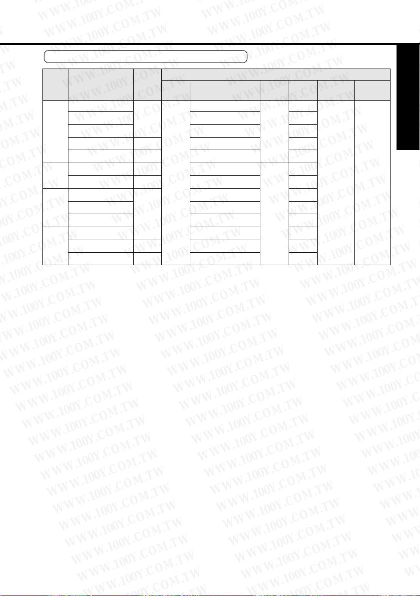
With the incremental type encoder: 2500P/r
Power
supply for
amplifier
MUDS3A1A1A
1-phase,
MUDS5A1A1A
100V
MUDS011A1A
MUDS021A1A
MUDS041A1A
MUDS022A1A
1-phase,
MUDS042A1A
200V
MUDS3A5A1A
3-phase/
1-
MUDS5A5A1A
phase,
MUDS015A1A
200V
MUDS023A1A
3-phase,
MUDS043A1A
200V
MUDS083A1A
Amplifier
Amplifier
Series
type
symbol
Type1
MUMS
Super
Type2
Type3
Type2
Type3
Type1
Type2
Type3
Low
inertia
Motor type
MUMS3AZ
MUMS5AZ
MUMS011A
MUMS021A
MUMS041A
MUMS022A
MUMS042A
MUMS3AZA
MUMS5AZA
MUMS012A
MUMS022A
MUMS042A
MUMS082A
****
****
****
****
****
****
****
****
****
****
****
****
****
Motor
Voltage
100V
200V
Output
rating
30W
50W
100W
200W
400W
200W
400W
30W
50W
100W
200W
400W
750W
Revolution
rating
3000r/min
Encoder
Incremental
2500P/r, 11
wires
Before Use
type
WWW.100Y.COM.TW WWW.100Y.COM.TW WWW.100Y.COM.TW
WWW.100Y.COM.TW WWW.100Y.COM.TW WWW.100Y.COM.TW
WWW.100Y.COM.TW WWW.100Y.COM.TW WWW.100Y.COM.TW
WWW.100Y.COM.TW WWW.100Y.COM.TW WWW.100Y.COM.TW
WWW.100Y.COM.TW WWW.100Y.COM.TW WWW.100Y.COM.TW
WWW.100Y.COM.TW WWW.100Y.COM.TW WWW.100Y.COM.TW
WWW.100Y.COM.TW WWW.100Y.COM.TW WWW.100Y.COM.TW
WWW.100Y.COM.TW WWW.100Y.COM.TW WWW.100Y.COM.TW
WWW.100Y.COM.TW WWW.100Y.COM.TW WWW.100Y.COM.TW
WWW.100Y.COM.TW WWW.100Y.COM.TW WWW.100Y.COM.TW
WWW.100Y.COM.TW WWW.100Y.COM.TW WWW.100Y.COM.TW
WWW.100Y.COM.TW WWW.100Y.COM.TW WWW.100Y.COM.TW
WWW.100Y.COM.TW WWW.100Y.COM.TW WWW.100Y.COM.TW
WWW.100Y.COM.TW WWW.100Y.COM.TW WWW.100Y.COM.TW
-11-
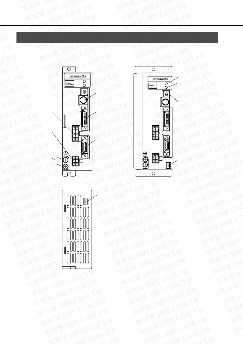
Parts Description
Amplifier
Example: MUDS023A1A
(3-phase, 200V 200W: Type 1)
STATUS
MSDS
ALM CODE
GAIN
CN
SER
Main power
input connector
(L1, L2, L3,P, B)
CN
POWER
CN
I/F
Communication
connector
CN SER
Controller
connection
(CN I/F)
Example: MUDS042A1A
(1-phase, 200V 400W: Type 3)
Status LED
MSDS
CN
POWER
STATUS
ALM CODE
GAIN
CN
SER
CN
I/F
Alarm code LED
Rotary switch
for gain (GAIN)
tuning
Motor
connection
(U, V, W, E)
Earth
connections
CN
MOTOR
CN
SIG
MON
CN
Encoder
connection
(CN SIG)
Check pins
CN
MOTOR
CN
SIG
Check pins
CN
(CN MON)
MON
(CN MON)
WWW.100Y.COM.TW WWW.100Y.COM.TW WWW.100Y.COM.TW
WWW.100Y.COM.TW WWW.100Y.COM.TW WWW.100Y.COM.TW
WWW.100Y.COM.TW WWW.100Y.COM.TW WWW.100Y.COM.TW
WWW.100Y.COM.TW WWW.100Y.COM.TW WWW.100Y.COM.TW
WWW.100Y.COM.TW WWW.100Y.COM.TW WWW.100Y.COM.TW
WWW.100Y.COM.TW WWW.100Y.COM.TW WWW.100Y.COM.TW
WWW.100Y.COM.TW WWW.100Y.COM.TW WWW.100Y.COM.TW
WWW.100Y.COM.TW WWW.100Y.COM.TW WWW.100Y.COM.TW
<Notes>
WWW.100Y.COM.TW WWW.100Y.COM.TW WWW.100Y.COM.TW
For detailed information for each of motor types, see the drawings in the Appendix
WWW.100Y.COM.TW WWW.100Y.COM.TW WWW.100Y.COM.TW
(App.50 to 52).
WWW.100Y.COM.TW WWW.100Y.COM.TW WWW.100Y.COM.TW
WWW.100Y.COM.TW WWW.100Y.COM.TW WWW.100Y.COM.TW
WWW.100Y.COM.TW WWW.100Y.COM.TW WWW.100Y.COM.TW
WWW.100Y.COM.TW WWW.100Y.COM.TW WWW.100Y.COM.TW
-12-
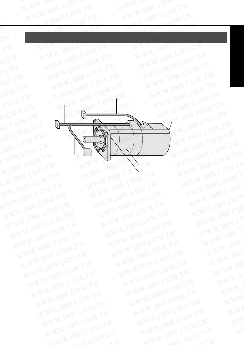
Motor
Example: Super Low-Inertia Motor (MUMS Series, 400W)
Encoder cable
Motor cable
Encoder
Brake cable
(Motor with electromagnetic brake only )
Flange
Frame
Mounting bolt holes (4)
Before Use
WWW.100Y.COM.TW WWW.100Y.COM.TW WWW.100Y.COM.TW
WWW.100Y.COM.TW WWW.100Y.COM.TW WWW.100Y.COM.TW
WWW.100Y.COM.TW WWW.100Y.COM.TW WWW.100Y.COM.TW
<Notes>
For detailed information for each of motor types, see the drawings in the Appendix
(App.48 & 49).
WWW.100Y.COM.TW WWW.100Y.COM.TW WWW.100Y.COM.TW
WWW.100Y.COM.TW WWW.100Y.COM.TW WWW.100Y.COM.TW
WWW.100Y.COM.TW WWW.100Y.COM.TW WWW.100Y.COM.TW
WWW.100Y.COM.TW WWW.100Y.COM.TW WWW.100Y.COM.TW
WWW.100Y.COM.TW WWW.100Y.COM.TW WWW.100Y.COM.TW
WWW.100Y.COM.TW WWW.100Y.COM.TW WWW.100Y.COM.TW
WWW.100Y.COM.TW WWW.100Y.COM.TW WWW.100Y.COM.TW
WWW.100Y.COM.TW WWW.100Y.COM.TW WWW.100Y.COM.TW
WWW.100Y.COM.TW WWW.100Y.COM.TW WWW.100Y.COM.TW
WWW.100Y.COM.TW WWW.100Y.COM.TW WWW.100Y.COM.TW
WWW.100Y.COM.TW WWW.100Y.COM.TW WWW.100Y.COM.TW
-13-
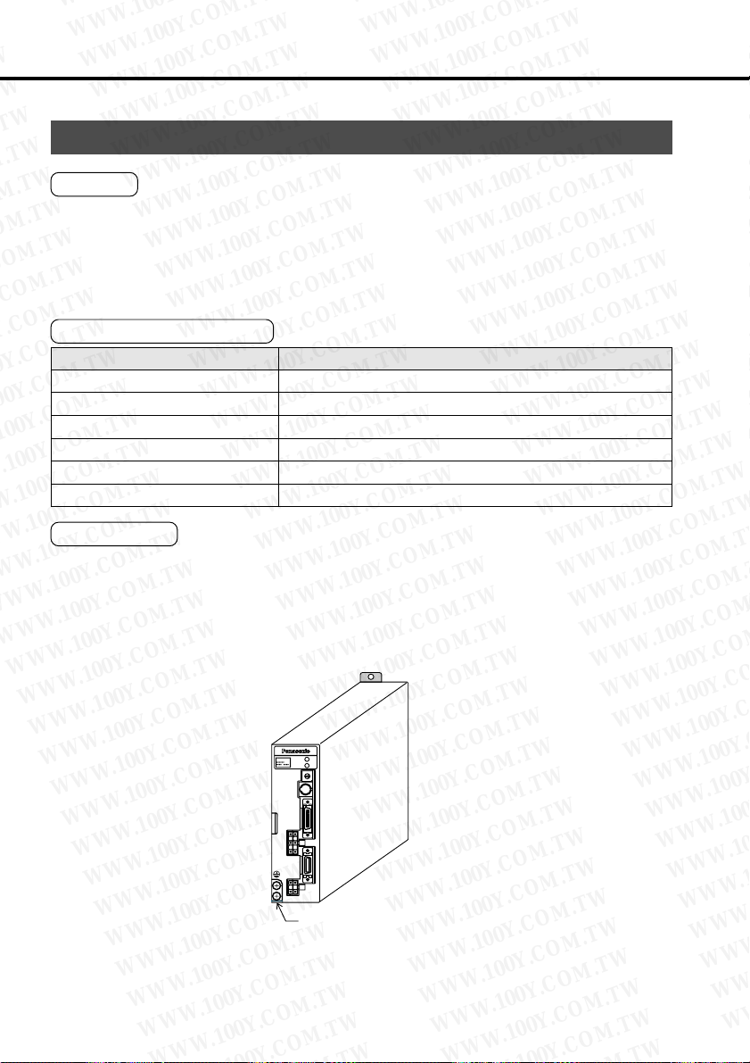
Installation
The amplifier and motor should be properly installed to avoid failures, mechanical damages and injuries.
Amplifier
Location
• Indoors, where the amplifier is not subjected to rain water and direct sun beams. Note
that the amplifier is not a waterproof structure.
• Avoid the place where the amplifier is subjected to corrosive gases, flammable gases,
grinding liquids, oil mists, iron powders and cutting particles.
• Place in a well-ventilated, and humid- and dust-free space.
• Place in a vibration-free space.
Environmental Conditions
Item
Ambient temperature
Ambient humidity
Storage temperature
Storage humidity
Vibration
Not greater than 90%RH (free from condensation)
0 to 55˚C (free from freezing)
-20 to 80˚C (free from condensation)
Not greater than 90%RH (free from condensation)
Not greater than 5.9m/s2 (0.6G) at 10 to 60 Hz
Altitude
How to Install
•
This is a rack-mount type.
Place the amplifier vertically. Allow enough space surrounding for ventilation.
Front panel mount type (recessed)
Conditions
Not greater than 1000 m
WWW.100Y.COM.TW WWW.100Y.COM.TW WWW.100Y.COM.TW
WWW.100Y.COM.TW WWW.100Y.COM.TW WWW.100Y.COM.TW
WWW.100Y.COM.TW WWW.100Y.COM.TW WWW.100Y.COM.TW
WWW.100Y.COM.TW WWW.100Y.COM.TW WWW.100Y.COM.TW
STATUS
WWW.100Y.COM.TW WWW.100Y.COM.TW WWW.100Y.COM.TW
WWW.100Y.COM.TW WWW.100Y.COM.TW WWW.100Y.COM.TW
WWW.100Y.COM.TW WWW.100Y.COM.TW WWW.100Y.COM.TW
WWW.100Y.COM.TW WWW.100Y.COM.TW WWW.100Y.COM.TW
WWW.100Y.COM.TW WWW.100Y.COM.TW WWW.100Y.COM.TW
WWW.100Y.COM.TW WWW.100Y.COM.TW WWW.100Y.COM.TW
WWW.100Y.COM.TW WWW.100Y.COM.TW WWW.100Y.COM.TW
MSDS
ALM CODE
GAIN
CN
SER
CN
I/F
CN
POWER
CN
SIG
CN
MOTOR
Earth connection (M4 screw) tightening torque
shall not exceed 0.39 ~ 0.59 N·m.
WWW.100Y.COM.TW WWW.100Y.COM.TW WWW.100Y.COM.TW
WWW.100Y.COM.TW WWW.100Y.COM.TW WWW.100Y.COM.TW
WWW.100Y.COM.TW WWW.100Y.COM.TW WWW.100Y.COM.TW
-14-
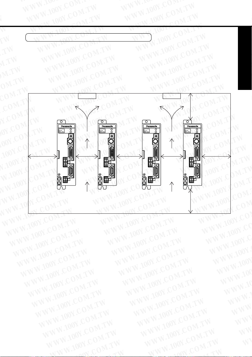
Mounting Direction and Space Requirements
• Allow enough space to ensure enough cooling.
• Install fans to provide a uniform distribution of temperature in the control box.
The airflow of fan is more than 0.43m
amplifier.
• Observe the environmental requirements for the control box, mentioned in the previous
page.
3
/min. And it should be located 10 cm away from the
Before Use
Fan Fan
min.
100mm
min.
40mm
STATUS
MSDS
ALM CODE
GAIN
CN
SER
CN
I/F
CN
POWER
min.
10mm
CN
SIG
CN
MOTOR
STATUS
MSDS
ALM CODE
GAIN
CN
SER
CN
I/F
CN
POWER
min.
10mm
CN
SIG
CN
MOTOR
STATUS
MSDS
ALM CODE
GAIN
CN
SER
CN
I/F
CN
POWER
min.
10mm
CN
SIG
CN
MOTOR
STATUS
MSDS
ALM CODE
GAIN
CN
SER
CN
I/F
CN
POWER
min.
CN
SIG
CN
MOTOR
40mm
min.
100mm
WWW.100Y.COM.TW WWW.100Y.COM.TW WWW.100Y.COM.TW
WWW.100Y.COM.TW WWW.100Y.COM.TW WWW.100Y.COM.TW
WWW.100Y.COM.TW WWW.100Y.COM.TW WWW.100Y.COM.TW
WWW.100Y.COM.TW WWW.100Y.COM.TW WWW.100Y.COM.TW
WWW.100Y.COM.TW WWW.100Y.COM.TW WWW.100Y.COM.TW
WWW.100Y.COM.TW WWW.100Y.COM.TW WWW.100Y.COM.TW
WWW.100Y.COM.TW WWW.100Y.COM.TW WWW.100Y.COM.TW
WWW.100Y.COM.TW WWW.100Y.COM.TW WWW.100Y.COM.TW
WWW.100Y.COM.TW WWW.100Y.COM.TW WWW.100Y.COM.TW
WWW.100Y.COM.TW WWW.100Y.COM.TW WWW.100Y.COM.TW
WWW.100Y.COM.TW WWW.100Y.COM.TW WWW.100Y.COM.TW
WWW.100Y.COM.TW WWW.100Y.COM.TW WWW.100Y.COM.TW
WWW.100Y.COM.TW WWW.100Y.COM.TW WWW.100Y.COM.TW
WWW.100Y.COM.TW WWW.100Y.COM.TW WWW.100Y.COM.TW
-15-
Installation
Motor
Location
•
Indoors, where the amplifier is not subjected to rain water and direct sun beams.
• Avoid the place where the amplifier is subjected to corrosive gases, flammable gases,
grinding liquids, oil mists, iron powders and cutting particles.
• Place in a well-ventilated, and humid- and dust-free space.
• Easy maintenance, inspections and cleaning is also important.
Environmental Conditions
Item
Ambient temperature
Ambient humidity
Storage temperature
Storage humidity
Vibration
Shock
Motor only
With gear
(At rotation)
Motor only
With gear
0 to 40˚C (free from freezing)
Not greater than 85%RH (free from condensation)
-20 to 80˚C (free from freezing)
Not greater than 85%RH (free from condensation)
49 m/s2 (5G) or less at rotation, 24.5 m/s2 (2.5G) or less at rest
High precision and normal type: 24 m/s2 (2G) or less
Standard type: 49 m/s2 (5G) or less
98 m/s2 (10G) or less
High precision and normal type: 98 m/s2 (10G) or less
Standard type: 24 m/s2 (2G) or less
Conditions
How to Install
The motor can be installed either vertically or horizontally. Observe the following notes.
WWW.100Y.COM.TW WWW.100Y.COM.TW WWW.100Y.COM.TW
• Horizontal mounting
WWW.100Y.COM.TW WWW.100Y.COM.TW WWW.100Y.COM.TW
Place the motor with the cable outlet facing down to prevent the entry of oil and water.
•
WWW.100Y.COM.TW WWW.100Y.COM.TW WWW.100Y.COM.TW
• Vertical mounting
• If a motor is coupled with a reduction gear, use a motor equipped with oil seal so that oil
WWW.100Y.COM.TW WWW.100Y.COM.TW WWW.100Y.COM.TW
in the reduction gear may not enter into the motor.
WWW.100Y.COM.TW WWW.100Y.COM.TW WWW.100Y.COM.TW
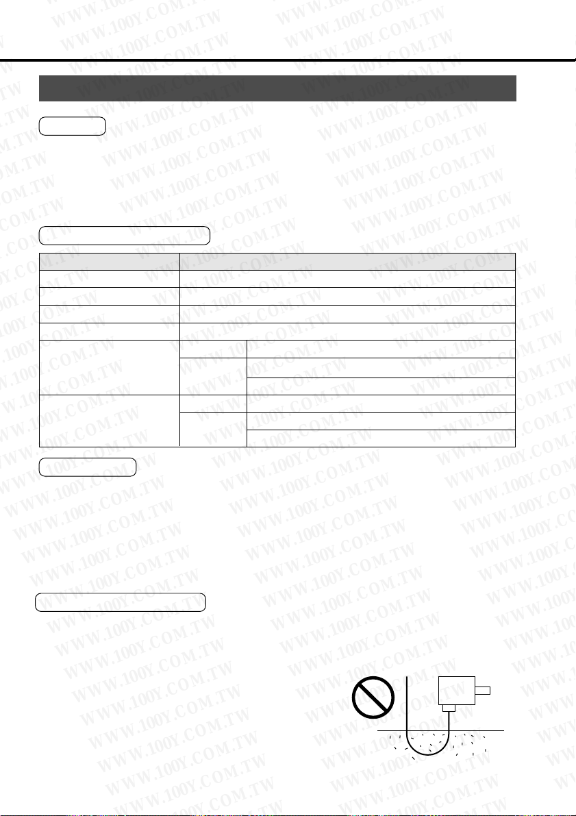
Oil and Water Protections
WWW.100Y.COM.TW WWW.100Y.COM.TW WWW.100Y.COM.TW
• This motor(IP65 rating) can be used where it is subjected
WWW.100Y.COM.TW WWW.100Y.COM.TW WWW.100Y.COM.TW
to water and/or oil drops, but is not water - or oil - proof.
WWW.100Y.COM.TW WWW.100Y.COM.TW WWW.100Y.COM.TW
Therefore, the motors should not be placed or used in
WWW.100Y.COM.TW WWW.100Y.COM.TW WWW.100Y.COM.TW
such environment.
•
If the motor is coupled with a reduction gear, use the motor
WWW.100Y.COM.TW WWW.100Y.COM.TW WWW.100Y.COM.TW
with oil seals to prevent the reduction gear oil from
WWW.100Y.COM.TW WWW.100Y.COM.TW WWW.100Y.COM.TW
entering into the motor.
•
Don't use the motor with the cables being immersed in oil
or water.
WWW.100Y.COM.TW WWW.100Y.COM.TW WWW.100Y.COM.TW
WWW.100Y.COM.TW WWW.100Y.COM.TW WWW.100Y.COM.TW
WWW.100Y.COM.TW WWW.100Y.COM.TW WWW.100Y.COM.TW
-16-
Cable
Motor
Oil and water

Cable: Stress Relieving
•
Make sure that the cables are not subjected to moments or vertical loads due to external
bending forces or self-weight at the cable outlets or connections.
• In case the motor is movable, secure the cable (proper one supplied together with the
motor) to a stationery part (e.g. floor), and it should be extended with an additional cable
which should be housed in a cable bearer so that bending stresses can be minimized.
• Make the bending radius of cables as large as possible.
(Minimum bend radius: 20 mm)
Permissible Shaft Load
• Make sure that both of radial and thrust load to be applied to the motor shaft during installation and running, are within the specified value of each model.
Pay extra attention to installing a rigid coupling (especially an excess bending load which may
•
cause the damages and/or wear of the shaft and bearings).
• Flexible coupling is recommended in order to keep the radial load smaller than the permissible value, which is designed exclusively for servo motors with high mechanical stiffness.
For the permissible shaft load, see "Allowable Shaft Loads Listing" in Appendix.
•
Installation Notes
•
Don't hit the shaft with a hammer directly while
attaching/detaching the coupling to the motor
shaft.(otherwise the encoder at the opposite
WWW.100Y.COM.TW WWW.100Y.COM.TW WWW.100Y.COM.TW
WWW.100Y.COM.TW WWW.100Y.COM.TW WWW.100Y.COM.TW
end of the shaft will be damaged).
• Try perfect alignment between shafts (misalignment may cause vibration, and damages of
the bearings).
WWW.100Y.COM.TW WWW.100Y.COM.TW WWW.100Y.COM.TW
WWW.100Y.COM.TW WWW.100Y.COM.TW WWW.100Y.COM.TW
WWW.100Y.COM.TW WWW.100Y.COM.TW WWW.100Y.COM.TW
Motor
WWW.100Y.COM.TW WWW.100Y.COM.TW WWW.100Y.COM.TW
WWW.100Y.COM.TW WWW.100Y.COM.TW WWW.100Y.COM.TW
WWW.100Y.COM.TW WWW.100Y.COM.TW WWW.100Y.COM.TW
WWW.100Y.COM.TW WWW.100Y.COM.TW WWW.100Y.COM.TW
WWW.100Y.COM.TW WWW.100Y.COM.TW WWW.100Y.COM.TW
WWW.100Y.COM.TW WWW.100Y.COM.TW WWW.100Y.COM.TW
WWW.100Y.COM.TW WWW.100Y.COM.TW WWW.100Y.COM.TW
WWW.100Y.COM.TW WWW.100Y.COM.TW WWW.100Y.COM.TW
WWW.100Y.COM.TW WWW.100Y.COM.TW WWW.100Y.COM.TW
-17-
Before Use
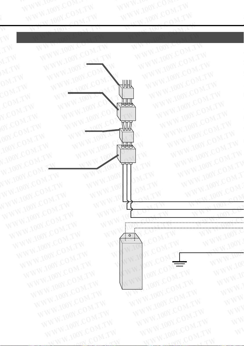
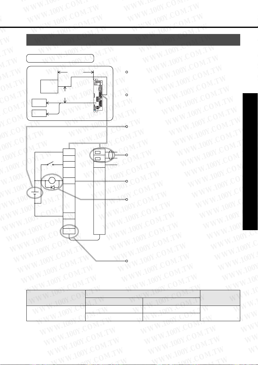
System Configuration and Wiring
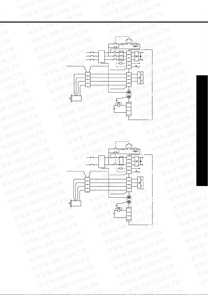
General Wiring Diagram
• Main Circuits
Non-Fuse Breaker (NFB)
Used to protect the power lines:
overcurrent will shut off the circuit.
Noise Filter (NF)
Prevents the external noise from the power
line, and reduces the effect of the noises generated by the servo motor.
Magnetic Contactor (MC)
Turns on/off the main power of the servo
motor.
Used together with a surge absorber.
Reactor (L)
Reduces the harmonic current in the
main power.
WWW.100Y.COM.TW WWW.100Y.COM.TW WWW.100Y.COM.TW
WWW.100Y.COM.TW WWW.100Y.COM.TW WWW.100Y.COM.TW
Terminals P and B
• In case of use under large regenerative
WWW.100Y.COM.TW WWW.100Y.COM.TW WWW.100Y.COM.TW
energy, connect an external
WWW.100Y.COM.TW WWW.100Y.COM.TW WWW.100Y.COM.TW
regenerative discharge resistor to P
WWW.100Y.COM.TW WWW.100Y.COM.TW WWW.100Y.COM.TW
and B terminals.
WWW.100Y.COM.TW WWW.100Y.COM.TW WWW.100Y.COM.TW
WWW.100Y.COM.TW WWW.100Y.COM.TW WWW.100Y.COM.TW
Ground
WWW.100Y.COM.TW WWW.100Y.COM.TW WWW.100Y.COM.TW
<Notes>
WWW.100Y.COM.TW WWW.100Y.COM.TW WWW.100Y.COM.TW
Where residual-current-operated
WWW.100Y.COM.TW WWW.100Y.COM.TW WWW.100Y.COM.TW
protective device (RCD) is used for
protection in case of direct or indirect
contact. Only RCD of Type B is allowed
on supply side of this Electronic
Equipment (EE).
WWW.100Y.COM.TW WWW.100Y.COM.TW WWW.100Y.COM.TW
WWW.100Y.COM.TW WWW.100Y.COM.TW WWW.100Y.COM.TW
WWW.100Y.COM.TW WWW.100Y.COM.TW WWW.100Y.COM.TW
WWW.100Y.COM.TW WWW.100Y.COM.TW WWW.100Y.COM.TW
Regenerative
discharge resistor
-18-
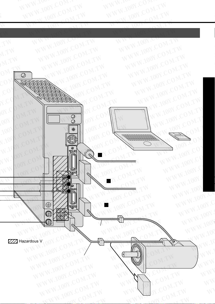
Personal computer
4
Preparations and Adjustments
STATUS
ALM CODE
GAIN
CN
SER
9
8
0
7
6
1
5
2
4
3
Communication
control software
PANATERM
“
CN SER
CN
I/F
CN
POWER
WWW.100Y.COM.TW WWW.100Y.COM.TW WWW.100Y.COM.TW
CN I/F
WWW.100Y.COM.TW WWW.100Y.COM.TW WWW.100Y.COM.TW
WWW.100Y.COM.TW WWW.100Y.COM.TW WWW.100Y.COM.TW
WWW.100Y.COM.TW WWW.100Y.COM.TW WWW.100Y.COM.TW
CN
MOTOR
CN
SIG
CN SIG
(to connect a PC or
controller)
(to connect a controller)
(to connect an encoder)
WWW.100Y.COM.TW WWW.100Y.COM.TW WWW.100Y.COM.TW
WWW.100Y.COM.TW WWW.100Y.COM.TW WWW.100Y.COM.TW
WWW.100Y.COM.TW WWW.100Y.COM.TW WWW.100Y.COM.TW
23
Hazardous Voltage
WWW.100Y.COM.TW WWW.100Y.COM.TW WWW.100Y.COM.TW
Others; Low Voltage circuit
Encoder cable
WWW.100Y.COM.TW WWW.100Y.COM.TW WWW.100Y.COM.TW
WWW.100Y.COM.TW WWW.100Y.COM.TW WWW.100Y.COM.TW
WWW.100Y.COM.TW WWW.100Y.COM.TW WWW.100Y.COM.TW
WWW.100Y.COM.TW WWW.100Y.COM.TW WWW.100Y.COM.TW
Motor cable
Power supply for motor
brake
(24VDC)
WWW.100Y.COM.TW WWW.100Y.COM.TW WWW.100Y.COM.TW
WWW.100Y.COM.TW WWW.100Y.COM.TW WWW.100Y.COM.TW
-19-
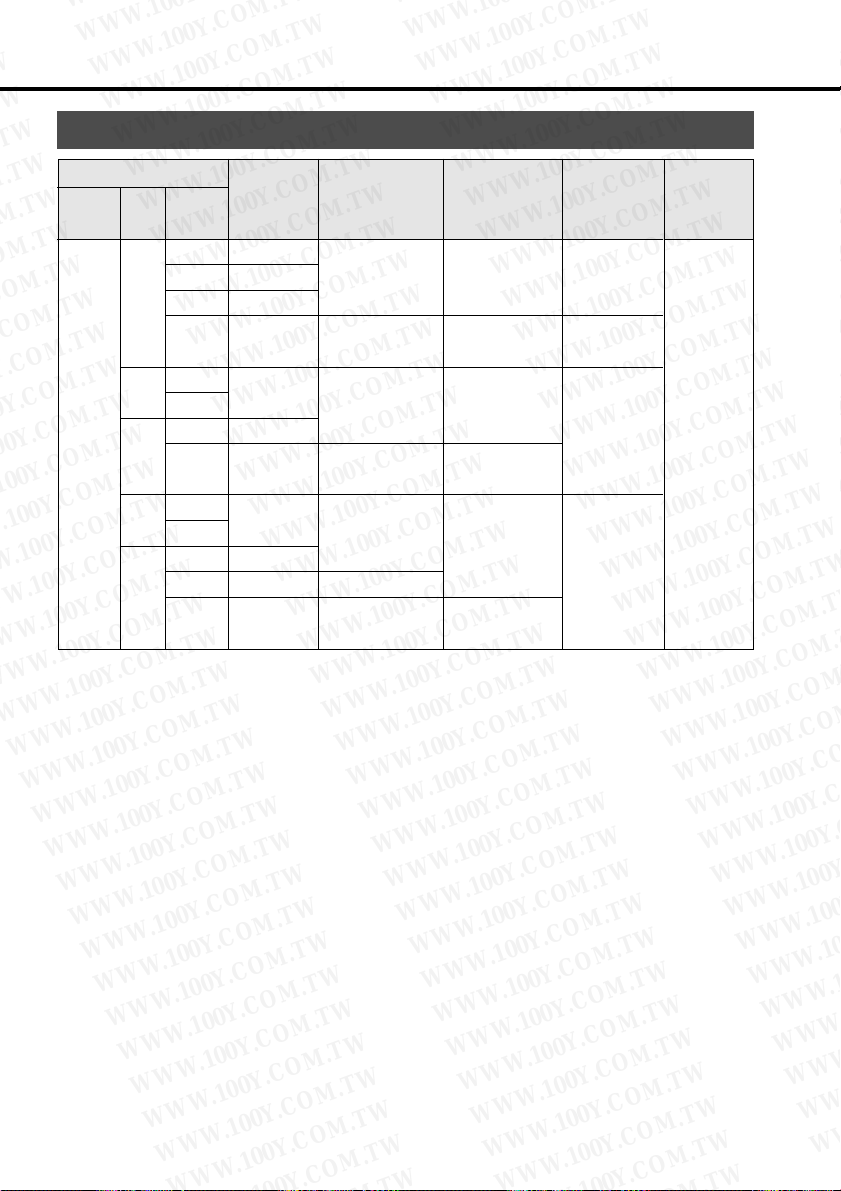
System Configuration and Wiring
List of Available Components
Amplifier
Voltage
Series
30 ~ 50W
100W
1-phase,
200W
100V
400W
30 ~ 50W
*1-phase,
100W
200V
MUDS
As these models with * are used for both 1-phase 200V and 3-phase 200V, make a choice
according to the power source.
200W
1-phase,
400W
200V
30 ~ 50W
*3-phase,
100W
200V
200W
400W
3-phase,
750W
200V
Output
Required Power
(at the rated load)
Approx. 0.3kVA
Approx.
0.4kVA
Approx.
0.5kVA
Approx.
1.0kVA
Approx.
0.3kVA
Approx.
0.5kVA
Approx.
0.9kVA
Approx.
0.3kVA
Approx.
0.5kVA
Approx. 0.9kVA
1.3kVA
Approx.
Circuit
breaker
(rated current)
BK251
(5A)
BK2101
(10A)
BK351
(5A)
BK3101
(10A)
BK351
(5A)
BK3101(10A)
BK3151
(15A)
Noise
filter
DVOP1441
DVOP1442
DVOP1441
DVOP1442
DVOP1441
DVOP1442
Magnetic contactor
(contacts)
BMFT61041N
(3P+1a)
BMFT61541N
(3P+1a)
BMFT61541N
(3P+1a)
MMFT61042N
(3P+1a)
0.75mm
~ 0.85mm
AWG 18
Main circuit wire diameter
(L1 , L2, L3,
U, V, W, E)
2
2
WWW.100Y.COM.TW WWW.100Y.COM.TW WWW.100Y.COM.TW
WWW.100Y.COM.TW WWW.100Y.COM.TW WWW.100Y.COM.TW
•
When these wires are used, wire length between circuit breaker and amplifier should be less than 3 m.
•
The model numbers of circuit breaker and magnetic contactors shown in the above list are manufactured by
WWW.100Y.COM.TW WWW.100Y.COM.TW WWW.100Y.COM.TW
Matsushita Electric Works, Ltd.
WWW.100Y.COM.TW WWW.100Y.COM.TW WWW.100Y.COM.TW
• Use the circuit breaker as shown in App.3 to meet relevant EC Directives.
WWW.100Y.COM.TW WWW.100Y.COM.TW WWW.100Y.COM.TW
•
The model number of noise filters (options) shown in the above are manufactured by Okaya Electric Industries
Co., Ltd.
WWW.100Y.COM.TW WWW.100Y.COM.TW WWW.100Y.COM.TW
WWW.100Y.COM.TW WWW.100Y.COM.TW WWW.100Y.COM.TW
<Notes>
WWW.100Y.COM.TW WWW.100Y.COM.TW WWW.100Y.COM.TW
• CN POWER, CN MOTOR and earth terminals
Wires should be copper conductors of a temperature rating of 60˚C or above.
WWW.100Y.COM.TW WWW.100Y.COM.TW WWW.100Y.COM.TW
•
Earth wire diameter should be 2.0 mm2 (AWG14) or larger.
WWW.100Y.COM.TW WWW.100Y.COM.TW WWW.100Y.COM.TW
•
Please also consider the electrochemical potentials between metal conductor including closed loop terminals.
The electrochemical potentials shall be less than 0.6V.
WWW.100Y.COM.TW WWW.100Y.COM.TW WWW.100Y.COM.TW
WWW.100Y.COM.TW WWW.100Y.COM.TW WWW.100Y.COM.TW
WWW.100Y.COM.TW WWW.100Y.COM.TW WWW.100Y.COM.TW
WWW.100Y.COM.TW WWW.100Y.COM.TW WWW.100Y.COM.TW
- 20 -
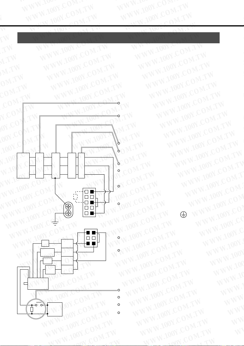
For 3-phase 200VAC
3-phase
200V
172167-1
White or yellow
Motor
Red
Black
Green/yellow
1
2
3
4
NFB
172159-1
tyco Electronics AMPtyco Electronics AMP
Noise filter
12~24V
MC
MC
5557-10R-210
5557-06R-210
V
DC
ON
ALM
MC
OFF
L
10
L1
8
L2
6
L3
5
3
1
4
6
W
3
9
ALM
13
COM –
P
N
P
P
N
B
U
V
E
For 1-phase 100V/200V
Single-phase 100V or
Single-phase 200V
NFB
172167-1 172159-1
tyco Electronics AMP tyco Electronics AMP
WWW.100Y.COM.TW WWW.100Y.COM.TW WWW.100Y.COM.TW
WWW.100Y.COM.TW WWW.100Y.COM.TW WWW.100Y.COM.TW
Red
White or yellow
Black
Green/yellow
1
2
3
4
WWW.100Y.COM.TW WWW.100Y.COM.TW WWW.100Y.COM.TW
WWW.100Y.COM.TW WWW.100Y.COM.TW WWW.100Y.COM.TW
Motor
WWW.100Y.COM.TW WWW.100Y.COM.TW WWW.100Y.COM.TW
WWW.100Y.COM.TW WWW.100Y.COM.TW WWW.100Y.COM.TW
Noise filter
12~24V
MC
5557-10R-210
5557-06R-210
V
DC
ON
MC
ALM
MC
OFF
L
10
L1
L2
6
L3
5
3
1
4
6
3
9
ALM
13
COM –
P
N
P
P
N
B
U
V
W
E
WWW.100Y.COM.TW WWW.100Y.COM.TW WWW.100Y.COM.TW
WWW.100Y.COM.TW WWW.100Y.COM.TW WWW.100Y.COM.TW
<Note>
WWW.100Y.COM.TW WWW.100Y.COM.TW WWW.100Y.COM.TW
In case that alarm occurs, construct the circuits so that the main power is switched off.
•
WWW.100Y.COM.TW WWW.100Y.COM.TW WWW.100Y.COM.TW
WWW.100Y.COM.TW WWW.100Y.COM.TW WWW.100Y.COM.TW
WWW.100Y.COM.TW WWW.100Y.COM.TW WWW.100Y.COM.TW
WWW.100Y.COM.TW WWW.100Y.COM.TW WWW.100Y.COM.TW
WWW.100Y.COM.TW WWW.100Y.COM.TW WWW.100Y.COM.TW
- 21 -
Preparations and Adjustments
System Configuration and Wiring
Main Circuits
Always ask to an electric engineer for wiring.
Don't turn on the main power until the wiring and connectings are completed, to avoid electric shocks.
Wiring Instructions
•
Make necessary connections.
For wire diameter, see List of Available Components (page 20).
•
Securely insert connectors.
See the nameplate of the amplifier to check
the power specification.
Install a non-fuse breaker or leakage breaker.
The latter should be a special one intended for
inverters, i.e. with a countermeasure against
higher harmonics.
Install a noise filter without fail.
Install a surge absorber to the magnetic
contactor coil.
Power
supply
D class ground: 100Ω max.
WWW.100Y.COM.TW WWW.100Y.COM.TW WWW.100Y.COM.TW
For wire diameter, see page 20.
WWW.100Y.COM.TW WWW.100Y.COM.TW WWW.100Y.COM.TW
WWW.100Y.COM.TW WWW.100Y.COM.TW WWW.100Y.COM.TW
WWW.100Y.COM.TW WWW.100Y.COM.TW WWW.100Y.COM.TW
WWW.100Y.COM.TW WWW.100Y.COM.TW WWW.100Y.COM.TW
WWW.100Y.COM.TW WWW.100Y.COM.TW WWW.100Y.COM.TW
NFB
NF MC L
CN
POWER
5
P
B
1
U
Red
White or
yellow
Black
WWW.100Y.COM.TW WWW.100Y.COM.TW WWW.100Y.COM.TW
Green
yellow
1
V
2
W
3
E
4
10
L1
L2
L3
6
CN
MOTOR
3
14
6
WWW.100Y.COM.TW WWW.100Y.COM.TW WWW.100Y.COM.TW
Motor
WWW.100Y.COM.TW WWW.100Y.COM.TW WWW.100Y.COM.TW
WWW.100Y.COM.TW WWW.100Y.COM.TW WWW.100Y.COM.TW
WWW.100Y.COM.TW WWW.100Y.COM.TW WWW.100Y.COM.TW
WWW.100Y.COM.TW WWW.100Y.COM.TW WWW.100Y.COM.TW
Power supply for
DC
elector magnetic brake
24V
(Min, 0.5A)
WWW.100Y.COM.TW WWW.100Y.COM.TW WWW.100Y.COM.TW
WWW.100Y.COM.TW WWW.100Y.COM.TW WWW.100Y.COM.TW
Install an AC reactor.
For three-phase 200V,connect L1(10pin), L2(8pin),
and L3(6pin).
For single-phase 100V and 200V, connect
L1(10pin) and L3(6pin).
Connect to the grounding system of the facility.
Never fail to connect between the amplifier's
protective earth terminal ( ) and control
board's protective earth terminal (ground plate)
in order to avoid electric shocks.
Ensure to connect matching in color between
the motor wires and terminals (U, V, W and E).
Don't short circuit or ground. Don't connect to
the main power.
The electromagnetic brake is not polar-sensitive.
For power capacities, see the App. 7.
For use of the brake, see "Holding Brake" in App. 6.
Install a surge absorber.
- 22 -
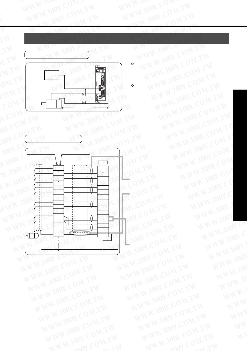
CN SIG Connector (For Encoder)
Wiring Instructions
The cable length between the amplifier and motor should be max. 20 m. If you use a longer
cable, contact the dealer or sales agent.
Separate these wiring min. 30 cm from the
main circuit wires. Don't lay these wires in
the same duct of the mains or bundle with
them.
Motor
Power
Encoder
min.30cm
max.20m
POWER
MSDS
ALARM
GAIN
RS232C
CN
I/F
CN
POWER
CN
SIG
CN
MOTOR
Preparations and Adjustment
Wiring Diagrams
ing cables see the "Optional Parts"
for connectors, and
When you prepare your own connect-
172171-1
tyco Electronics AMP
Yellow
Orange
Yellow
Green
Blue
Red
Pink
Light
Blue
Purple
WWW.100Y.COM.TW WWW.100Y.COM.TW WWW.100Y.COM.TW
WWW.100Y.COM.TW WWW.100Y.COM.TW WWW.100Y.COM.TW
White
Black
WWW.100Y.COM.TW WWW.100Y.COM.TW WWW.100Y.COM.TW
tyco Electronics AMP
5
Z
6
Z
3
B
4
B
1
A
2
A
11
RX
12
RX
13
+5V
14
0V
15
FG
172163-1
11
12
9
10
7
8
17
18
3
1
4
2
20
CN SIG
Z
Z
B
B
A
A
RX
RX
+5V
0V
+5V
0V
FG
WWW.100Y.COM.TW WWW.100Y.COM.TW WWW.100Y.COM.TW
WWW.100Y.COM.TW WWW.100Y.COM.TW WWW.100Y.COM.TW
Moter side
Connecting cable
Driver side
WWW.100Y.COM.TW WWW.100Y.COM.TW WWW.100Y.COM.TW
WWW.100Y.COM.TW WWW.100Y.COM.TW WWW.100Y.COM.TW
1) Follow the wiring diagram and use the
2) Wire material: 0.18 mm
2
(AWG24) or more,
shielded twist-paired wire Å@with an
enough bending durability,
3) Signal/power paired wires should be of a
twist-paired type.
4) Shield:
• The shield at the amplifier side should be
connected to Pin 20 (FG) of CN SIG Connector.
• The shield at the motor side should be connected to: connector of 15 pins type
5) If the cable is longer than 10 m, the encoder power line (+5V and 0V) should be
dual per the figure shown left.
6) Other terminals should be left
unconnected.
WWW.100Y.COM.TW WWW.100Y.COM.TW WWW.100Y.COM.TW
WWW.100Y.COM.TW WWW.100Y.COM.TW WWW.100Y.COM.TW
WWW.100Y.COM.TW WWW.100Y.COM.TW WWW.100Y.COM.TW
WWW.100Y.COM.TW WWW.100Y.COM.TW WWW.100Y.COM.TW
WWW.100Y.COM.TW WWW.100Y.COM.TW WWW.100Y.COM.TW
WWW.100Y.COM.TW WWW.100Y.COM.TW WWW.100Y.COM.TW
WWW.100Y.COM.TW WWW.100Y.COM.TW WWW.100Y.COM.TW
- 23 -
System Configuration and Wiring
MSDS
CN
I/F
ALM CODE
STATUS
GAIN
CN
SER
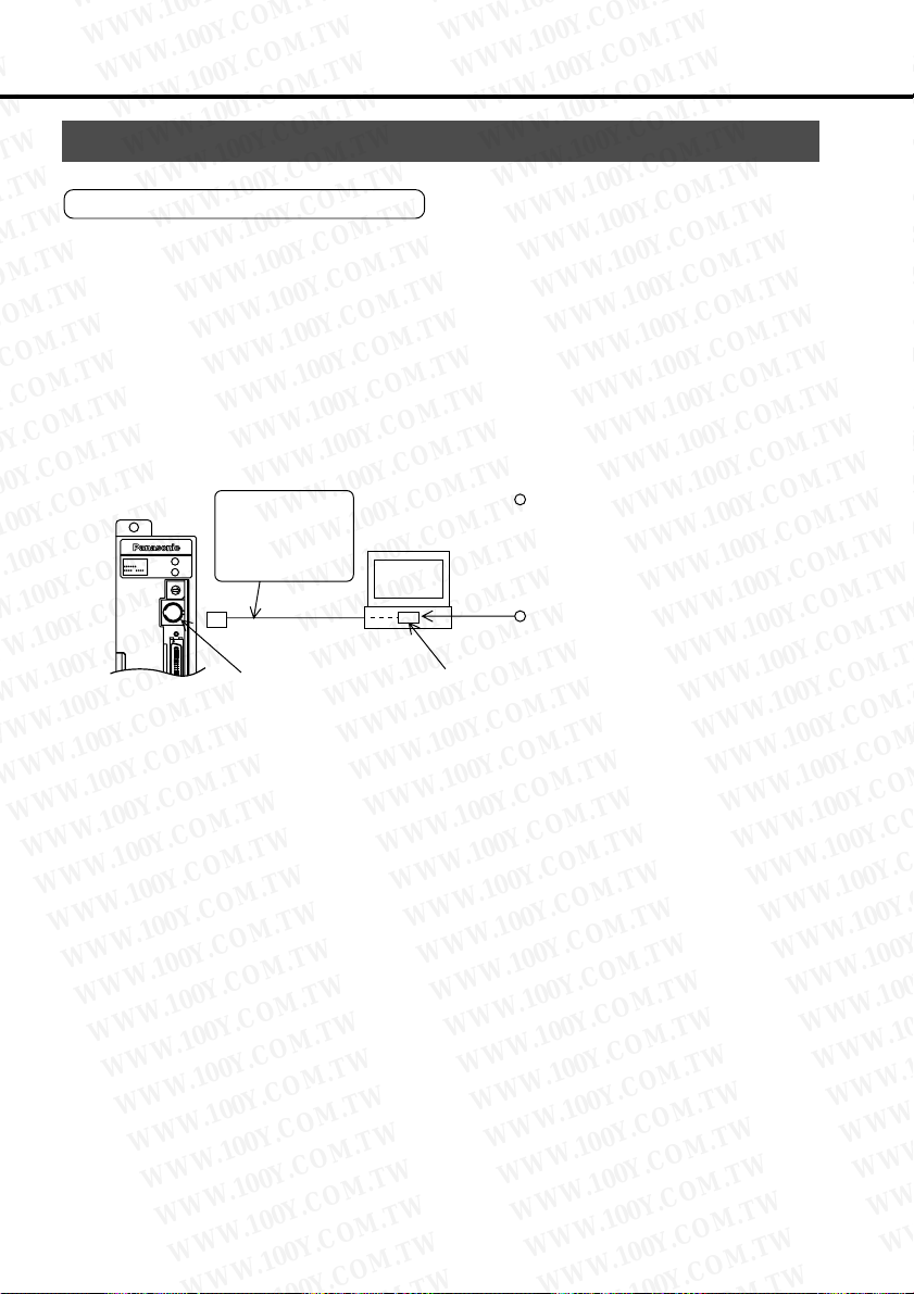
CN SER Connector
For RC232C communications
Connect a personal computer to the amplifier with RS232C at 1:1, and use the
communication control software "PANATERM“" (Option). Operate "PANATERM“"
on the personal computer. Convenient functions of high operability can be
obtained such as monitor and parameter setting and setting change and
waveform graphic display.
Connection
Exclusive
connection cable
(Option)
See App. 44.
CN SER RS232C connector
Personal
computer
Insert and pull out connector
after cutting power to both
personal computer and
amplifier
Securely tighten the fixing
screw
WWW.100Y.COM.TW WWW.100Y.COM.TW WWW.100Y.COM.TW
WWW.100Y.COM.TW WWW.100Y.COM.TW WWW.100Y.COM.TW
WWW.100Y.COM.TW WWW.100Y.COM.TW WWW.100Y.COM.TW
WWW.100Y.COM.TW WWW.100Y.COM.TW WWW.100Y.COM.TW
WWW.100Y.COM.TW WWW.100Y.COM.TW WWW.100Y.COM.TW
WWW.100Y.COM.TW WWW.100Y.COM.TW WWW.100Y.COM.TW
WWW.100Y.COM.TW WWW.100Y.COM.TW WWW.100Y.COM.TW
WWW.100Y.COM.TW WWW.100Y.COM.TW WWW.100Y.COM.TW
WWW.100Y.COM.TW WWW.100Y.COM.TW WWW.100Y.COM.TW
WWW.100Y.COM.TW WWW.100Y.COM.TW WWW.100Y.COM.TW
WWW.100Y.COM.TW WWW.100Y.COM.TW WWW.100Y.COM.TW
WWW.100Y.COM.TW WWW.100Y.COM.TW WWW.100Y.COM.TW
WWW.100Y.COM.TW WWW.100Y.COM.TW WWW.100Y.COM.TW
WWW.100Y.COM.TW WWW.100Y.COM.TW WWW.100Y.COM.TW
- 24 -
List of Available Components
CN I/F Connector (For Controller)
Wiring Instructions
Controller
Power
supply
Motor
max. 3 m
min. 30 cm
POWER
MSDS
ALARM
GAIN
RS232C
CN
I/F
CN
POWER
CN
SIG
CN
MOTOR
Place the peripheral devices such as the
controller max. 3 m away from the amplifier.
Separate these wiring min. 30 cm from the main
circuit wires. Don't lay these wires in the same
duct of the mains or bundle with them.
T
he control power (VDC) between COM+ and COM- should
Preparations and Adjustments
be supplied by the customer (recommended voltage:
+12VDC to +24VDC).
COM+
GND
1
2
Use a shielded twist-paired type for the wiring
of pulse input, encoder signal output, etc.
Do not apply power higher than 24V or 50mA to control
V
DC
signal output terminal.
If you directly activate a relay using the control
signal,install a diode in parallel to the relay as
WWW.100Y.COM.TW WWW.100Y.COM.TW WWW.100Y.COM.TW
WWW.100Y.COM.TW WWW.100Y.COM.TW WWW.100Y.COM.TW
WWW.100Y.COM.TW WWW.100Y.COM.TW WWW.100Y.COM.TW
COM-
FG
CN I/F
shown in the left figure. Without a diode or with
it but placed in the opposite direction, the
amplifier will be damaged.
WWW.100Y.COM.TW WWW.100Y.COM.TW WWW.100Y.COM.TW
WWW.100Y.COM.TW WWW.100Y.COM.TW WWW.100Y.COM.TW
WWW.100Y.COM.TW WWW.100Y.COM.TW WWW.100Y.COM.TW
WWW.100Y.COM.TW WWW.100Y.COM.TW WWW.100Y.COM.TW
• CN I/F Connector Specifications
WWW.100Y.COM.TW WWW.100Y.COM.TW WWW.100Y.COM.TW
Receptacle on the
amplifier side
WWW.100Y.COM.TW WWW.100Y.COM.TW WWW.100Y.COM.TW
10226-52A2JL
WWW.100Y.COM.TW WWW.100Y.COM.TW WWW.100Y.COM.TW
WWW.100Y.COM.TW WWW.100Y.COM.TW WWW.100Y.COM.TW
• The CN I/F pins assignment is shown in "Optional Parts" in Appendix.
Connector to controller side
Part description
Solder type plug (Soldering type)
Connector cover
The Frame Ground (FG) is connected to
an earth terminal in the amplifier.
Part No.
10126-3000VE
10326-52A0-008
Manufacturer
Sumitomo
three M
WWW.100Y.COM.TW WWW.100Y.COM.TW WWW.100Y.COM.TW
WWW.100Y.COM.TW WWW.100Y.COM.TW WWW.100Y.COM.TW
WWW.100Y.COM.TW WWW.100Y.COM.TW WWW.100Y.COM.TW
- 25 -

System configutration and wiring
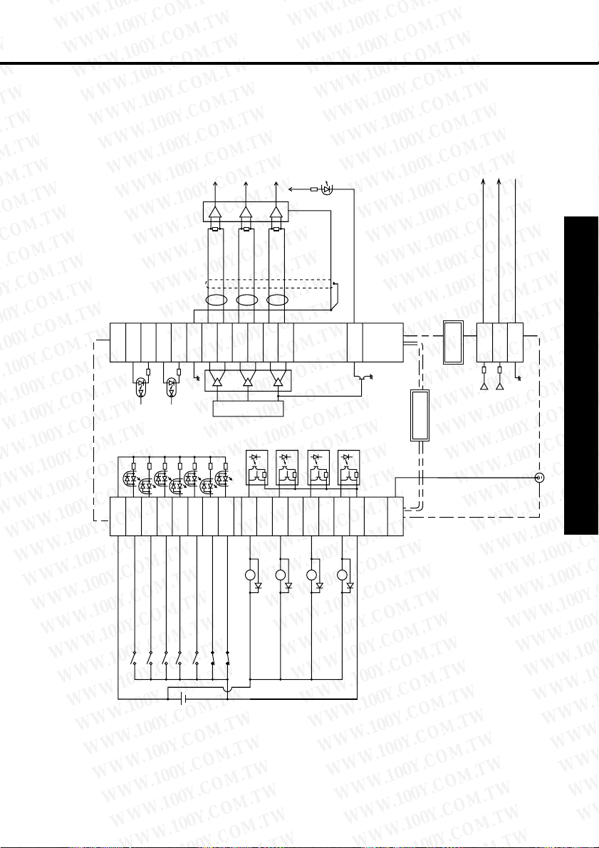
1
4.7k
Ω
220
Ω
220
Ω
COM+
PULS2
SIGN1
SIGN2
GND
OA+
OA
OB+
OB
OZ+
OZ
CZ
SPM
IM
22
23
24
25
14
15
16
17
20
330Ω
330Ω
330Ω
1
2
3
21
18
19
1K
1K
PULS1
SRV-ON
A-CLR
CL
GAIN
DIV
CWL
CCWL
ALM
COIN
BRKOFF
COM-
WARN
CN I/F
FG
2
3
4
5
6
7
8
9
10
11
13
12
26
V
DC
12~24V
CN MON
GND
Monitor pin
Monitor pin
If this is an open collector I/F,
see P1 in page 33.
Velocity monitor
output
Torque monitor
output
Command
pulse input
A-phase
output
B-phase
output
Z-phase
output
Z-phase output (open collector)
2nd gain switching
Servo-ON
Alarm clear
Position error counter clear
Command pulse scaler switch
CW overtravel inhibit
CCW overtravel inhibit
Servo alarm
In-position
Mechanical brake release
Alarm
(Pr09)
Scaler
Circuits Available for Typical Control Modes
WWW.100Y.COM.TW WWW.100Y.COM.TW WWW.100Y.COM.TW
WWW.100Y.COM.TW WWW.100Y.COM.TW WWW.100Y.COM.TW
WWW.100Y.COM.TW WWW.100Y.COM.TW WWW.100Y.COM.TW
WWW.100Y.COM.TW WWW.100Y.COM.TW WWW.100Y.COM.TW
WWW.100Y.COM.TW WWW.100Y.COM.TW WWW.100Y.COM.TW
WWW.100Y.COM.TW WWW.100Y.COM.TW WWW.100Y.COM.TW
WWW.100Y.COM.TW WWW.100Y.COM.TW WWW.100Y.COM.TW
WWW.100Y.COM.TW WWW.100Y.COM.TW WWW.100Y.COM.TW
WWW.100Y.COM.TW WWW.100Y.COM.TW WWW.100Y.COM.TW
WWW.100Y.COM.TW WWW.100Y.COM.TW WWW.100Y.COM.TW
WWW.100Y.COM.TW WWW.100Y.COM.TW WWW.100Y.COM.TW
WWW.100Y.COM.TW WWW.100Y.COM.TW WWW.100Y.COM.TW
WWW.100Y.COM.TW WWW.100Y.COM.TW WWW.100Y.COM.TW
• CN I/F Wiring for Position Control
WWW.100Y.COM.TW WWW.100Y.COM.TW WWW.100Y.COM.TW
- 26 -
1
4.7k
Ω
COM+
PULS2
SIGN1
SIGN2
OA+
OA
OB+
OB
OZ+
OZ
CZ
SPM
IM
22
23
24
25
15
GND
14
16
17
20
21
1
2
3
18
19
1K
1K
PULS1
SRV-ON
A-CLR
INTSPD2
ZEROSPD
INTSPD1
CWL
CCWL
ALM
COIN
BRKOFF
WARN
COM
-
CN I/F
FG
3
4
2
5
6
7
8
9
10
11
12
13
26
V
DC
12~24V
220
Ω
220
Ω
CN MON
GND
330Ω
330Ω
330Ω
Servo-ON
Alarm clear
CCW overtravel inhibit
A-phase
output
B-phase
output
Z-phase
output
CW overtravel inhibit
Servo alarm
At-speed
Mechanical brake release
Alarm
(Pr09)
Internal vel .cmnd.select 1
Internal vel .cmnd.select 2
Speed zero clamp
Scaler
Z-phase output (open collector)
Monitor pin
Monitor pin
Velocity monitor
output
Torque monitor
output
Preparations and Adjustments
WWW.100Y.COM.TW WWW.100Y.COM.TW WWW.100Y.COM.TW
WWW.100Y.COM.TW WWW.100Y.COM.TW WWW.100Y.COM.TW
WWW.100Y.COM.TW WWW.100Y.COM.TW WWW.100Y.COM.TW
WWW.100Y.COM.TW WWW.100Y.COM.TW WWW.100Y.COM.TW
WWW.100Y.COM.TW WWW.100Y.COM.TW WWW.100Y.COM.TW
WWW.100Y.COM.TW WWW.100Y.COM.TW WWW.100Y.COM.TW
WWW.100Y.COM.TW WWW.100Y.COM.TW WWW.100Y.COM.TW
WWW.100Y.COM.TW WWW.100Y.COM.TW WWW.100Y.COM.TW
WWW.100Y.COM.TW WWW.100Y.COM.TW WWW.100Y.COM.TW
WWW.100Y.COM.TW WWW.100Y.COM.TW WWW.100Y.COM.TW
WWW.100Y.COM.TW WWW.100Y.COM.TW WWW.100Y.COM.TW
WWW.100Y.COM.TW WWW.100Y.COM.TW WWW.100Y.COM.TW
WWW.100Y.COM.TW WWW.100Y.COM.TW WWW.100Y.COM.TW
• CN I/F Wiring for Internal Velocity Control
WWW.100Y.COM.TW WWW.100Y.COM.TW WWW.100Y.COM.TW
- 27 -
System configuration and wiring
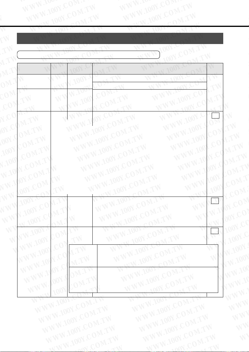
CN I/F Connector
Input Signals (Common) and their Functions
Signal
Control signal
power
(+)
Control signal
(-)
power
Servo-ON
Alarm
WWW.100Y.COM.TW WWW.100Y.COM.TW WWW.100Y.COM.TW
clear
WWW.100Y.COM.TW WWW.100Y.COM.TW WWW.100Y.COM.TW
Position error
WWW.100Y.COM.TW WWW.100Y.COM.TW WWW.100Y.COM.TW
counter
WWW.100Y.COM.TW WWW.100Y.COM.TW WWW.100Y.COM.TW
clear/Internal
WWW.100Y.COM.TW WWW.100Y.COM.TW WWW.100Y.COM.TW
command
velocity
WWW.100Y.COM.TW WWW.100Y.COM.TW WWW.100Y.COM.TW
selection 2
WWW.100Y.COM.TW WWW.100Y.COM.TW WWW.100Y.COM.TW
WWW.100Y.COM.TW WWW.100Y.COM.TW WWW.100Y.COM.TW
Pin
Symbol Function
No.
COMÅ{
1
13
COMÅ|
2
SRV-ON
<Notes>
1. This signal becomes effective about two seconds after power on
(see the Timing chart).
2. Don't use this Servo-ON or Servo-OFF signal to turn on or off the
motor. (See App.8)
Allow at least 100ms delay after the amplifier is enabled before any
•
command input is entered.
•
By opening the connection to COM- , the amplifier will be disabled(Servo-OFF) and
the current flow to the motor will be inhibited.
•
Operation of the dynamic brake and clearing action of the position error counter can be
selected using Pr69 (Sequence under Servo-OFF).
3
A-CLR
4
CL/
INTSPD2
Position
control
Internal
velocity
control
•
Connect to (+) of an external power supply(12VDC to 24VDC).
•
Use power supply of 12V±10%Å`24V±10%
•
Connect to (-) of an external power supply(12VDC to 24VDC).
•
The required capacity depends on the I/O circuit configuration.
0.5A or larger is recommended.
•
When this signal is connected to COM-, the dynamic brake will be
released and the amplifier is enabled. (Servo-ON).
•
If the COM- connection is kept closed for more than 120 ms,
the alarm status will be cleared.
•
Some alarms cannot be cleared by this input.
For details, see Protective Functions on page 60.
The function differs depending on the control mode.
• Clears the position error counter. Connect to COMto clear the counter.
•
Use Pr4D to select the clear mode (0 Default: level 1: Edge)
•
The internal velocity selection 2 (input) is valid. 4 kinds of
velocity settings are available by combination with DIV/
INTSPD1 input. See control mode setting Pr02 (APP. 16).
I/F
circuit
Å\Å\
SI
page 33
SI
page 33
SI
page 33
WWW.100Y.COM.TW WWW.100Y.COM.TW WWW.100Y.COM.TW
WWW.100Y.COM.TW WWW.100Y.COM.TW WWW.100Y.COM.TW
WWW.100Y.COM.TW WWW.100Y.COM.TW WWW.100Y.COM.TW
WWW.100Y.COM.TW WWW.100Y.COM.TW WWW.100Y.COM.TW
WWW.100Y.COM.TW WWW.100Y.COM.TW WWW.100Y.COM.TW
WWW.100Y.COM.TW WWW.100Y.COM.TW WWW.100Y.COM.TW
- 28 -
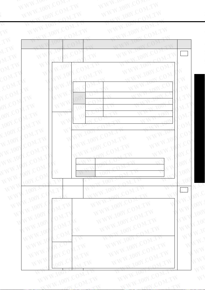
Signal
Gain
switching/
Speed zero
clamp
WWW.100Y.COM.TW WWW.100Y.COM.TW WWW.100Y.COM.TW
Pin
Symbol Function
No.
GAIN/
5
ZEROSPD
Position
control
Internal
velocity
control
The function differs depending on the control mode.
•
The functions depend on the value of Pr30.
•
Gain switching input results. Input for switching PI/P
operation and No. 1/No. 2 gains.
Connection
Pr30
to COM-
value
0
Open
(Default)
Close
1
Open
Close
At Pr31 value of 2
•
For No.2 Gain change Funcution, see Protective Adjustments on page 57.
•
Speed zero clamp input results. With COM- open, the
velocity command is considered zero.
• This input can be made disabled using Pr06.
• Default: Contact is set. With COM- open, the velocity
command is considered zero.
Pr06 value
0
1
[Default]
Speed loop:PI(ProportionalÅEIntegration) operation
Speed loop: P (Proportion) operation
#1 gain selection (Pr10, 11, 12, 13, 14)
#2 gain selection (Pr 18, 19, 1A, 1B, 1C)
ZEROSPD is disabled.
ZEROSPD is enabled
Function
Meaning
I/F
circuit
SI
page 33
WWW.100Y.COM.TW WWW.100Y.COM.TW WWW.100Y.COM.TW
WWW.100Y.COM.TW WWW.100Y.COM.TW WWW.100Y.COM.TW
Command
pulse scaler
WWW.100Y.COM.TW WWW.100Y.COM.TW WWW.100Y.COM.TW
switch/
Internal
WWW.100Y.COM.TW WWW.100Y.COM.TW WWW.100Y.COM.TW
command
WWW.100Y.COM.TW WWW.100Y.COM.TW WWW.100Y.COM.TW
velocity
WWW.100Y.COM.TW WWW.100Y.COM.TW WWW.100Y.COM.TW
selection 1
6
INTSPD1
Position
control
DIV/
WWW.100Y.COM.TW WWW.100Y.COM.TW WWW.100Y.COM.TW
WWW.100Y.COM.TW WWW.100Y.COM.TW WWW.100Y.COM.TW
WWW.100Y.COM.TW WWW.100Y.COM.TW WWW.100Y.COM.TW
WWW.100Y.COM.TW WWW.100Y.COM.TW WWW.100Y.COM.TW
Internal
velocity
control
The function differs depending on the control mode.
This is the input to switch command pulse scaler.
•
•
With COM- closed, the numerator of the command scaler is changed
from the value stored in Pr46 (Numerator of 1st Command Scaler) to
the value stored in Pr47 (Numerator of 2nd Command Scaler).
<Note>
Don't enter command pulses 10 ms after or before switching.
•
The internal velocity selection 1 (input) is valid. 4 kinds of velocity
settings are available by the combination with CL/INTSPD2 input.
• See control mode setting Pr02 (APP. 16).
SI
page 33
WWW.100Y.COM.TW WWW.100Y.COM.TW WWW.100Y.COM.TW
WWW.100Y.COM.TW WWW.100Y.COM.TW WWW.100Y.COM.TW
WWW.100Y.COM.TW WWW.100Y.COM.TW WWW.100Y.COM.TW
- 29 -
Preparations and Adjustments
System configuration and wiring
Signal
CW overtravel
inhibit
CCW overtravel
inhibit
Pin
Symbol Function
No.
7
CWL
8
CCWL
•
If COM- is opened when the movable part of the
machine has moved to CW exceeding the limit, the
motor does not generate torque.
•
If the COM- is opened when the movable part of the
machine has moved CCW exceeding the limit, the
motor does not generate torque.
•
When Pr04 (Overtravel Limit Input Disabled) = 1, CWL
and CCWL inputs are disabled. The default is
"Disabled" (1).
•
The dynamic brake can be made operable during CWL/
CCWL inputs valid. Use Pr66 (Dynamic Brake
Inactivation at Overtravel Limit) to make the dynamic
brake operable. The default is to allow the dynamic
brake to operate. (Pr66 value is 0.)
I/F
circuit
SI
page 33
SI
page 33
Input Signals (Position Control) and their Functions
Signal
Command
pulse
WWW.100Y.COM.TW WWW.100Y.COM.TW WWW.100Y.COM.TW
Command
WWW.100Y.COM.TW WWW.100Y.COM.TW WWW.100Y.COM.TW
sign
WWW.100Y.COM.TW WWW.100Y.COM.TW WWW.100Y.COM.TW
WWW.100Y.COM.TW WWW.100Y.COM.TW WWW.100Y.COM.TW
WWW.100Y.COM.TW WWW.100Y.COM.TW WWW.100Y.COM.TW
Pin
Symbol Function
No.
22
23
24
25
PULS1
PULS2
SIGN1
SIGN2
This is the input terminal for command pulses. The maximum allowable
•
input frequency is 500 kpps for line amplifier input and 200 kpps for
open collector input. The amplifier is the high-speed photocoupler
of TOSHIBA TLP554 or equivalent.
• The input impedance of PULSE and SIGN signals is 220Ω.
•
Command pulses can be input in three different ways. Use Pr42 to
select one of the following. (See App.26.)
1) Quadrature (A and B) input
2) CW (PULSE)/CCW (SIGN) pulse input
3)
Command pulse (PULS)/Sign (SIGN) input
I/F
circuit
PI
page 33
WWW.100Y.COM.TW WWW.100Y.COM.TW WWW.100Y.COM.TW
WWW.100Y.COM.TW WWW.100Y.COM.TW WWW.100Y.COM.TW
WWW.100Y.COM.TW WWW.100Y.COM.TW WWW.100Y.COM.TW
WWW.100Y.COM.TW WWW.100Y.COM.TW WWW.100Y.COM.TW
WWW.100Y.COM.TW WWW.100Y.COM.TW WWW.100Y.COM.TW
WWW.100Y.COM.TW WWW.100Y.COM.TW WWW.100Y.COM.TW
WWW.100Y.COM.TW WWW.100Y.COM.TW WWW.100Y.COM.TW
WWW.100Y.COM.TW WWW.100Y.COM.TW WWW.100Y.COM.TW
WWW.100Y.COM.TW WWW.100Y.COM.TW WWW.100Y.COM.TW
- 30 -
 Loading...