

Panasonic Minas-LIQI Technical Reference

No. SR-ZSV00039
TECHNICAL REFERENCE
MODE L
Product name: AC Servo Amplifier
Product number: Minas-LIQI series
Issued on March 26, 2012
(REVISION . . )
Received by
Date:
CHECKED CHECKED CHECKED DESIGNED
Motor Business Unit, Appliances Company
Panasonic Corporation
7-1-1 Morofuku, Daito-City, Osaka 574-0044, Japan

REVISIONS
№SR-ZSV00039
Date Page Sym
Mar. 26, 2012
- -
REVISION Signed
NEWLY ISSUED
Kang,Wu
Motor Business Unit, Appliances Company, Panasonic Corporation

№SR-ZSV00039
Contents
1. Specification Overview.........................................................................................................................1
2. Specifications of Interface.....................................................................................................................2
2-1 Specifications of Input Signal of I/F Connector.................................................................................2
2-2 Specifications of Output Signal of I/F Connector..............................................................................4
2-3 Input/Output Signal Allocation ..........................................................................................................5
2-3-1 Allocation of Input Signal ..........................................................................................................5
2-3-2 Allocation of Output Signal .......................................................................................................8
3. Specifications of Front Panel ..............................................................................................................10
3-1 Rotary switch(RSW) ........................................................................................................................10
3-2 7 segment LED.................................................................................................................................11
4. Basic function .....................................................................................................................................12
4-1 Setting Rotational Direction.............................................................................................................12
4-2 Position control ................................................................................................................................13
4-2-1 Command Pulse Input ..............................................................................................................13
4-2-2 Command Scaling (Electronic Gear)........................................................................................15
4-2-3 Position Command Filter..........................................................................................................16
4-2-4 Pulse Regeneration...................................................................................................................18
4-2-5 Counter Clear (CL)...................................................................................................................21
4-2-6 In-position Output (INP) ..........................................................................................................22
4-2-7 Command Pulse Inhibition (INH) ............................................................................................23
4-3 Setting of Regenerative Resistor ......................................................................................................24
5. Gain Adjustment / Damping Control Functions .................................................................................25
5-1 Automatic Adjusting Function.........................................................................................................25
5-1-1 Real-time Auto Tuning.............................................................................................................26
5-1-2 Adaptive Filter..........................................................................................................................31
5-2 Manual Adjustment..........................................................................................................................33
5-2-1 Block Diagram of Position Control Mode................................................................................34
5-2-2 Gain Switching Function..........................................................................................................35
5-2-3 Notch Filter ..............................................................................................................................39
5-2-4 Damping Control......................................................................................................................41
5-2-5 Feed Forward Function ............................................................................................................44
5-2-6 3rd Gain Switching...................................................................................................................46
5-2-7 Friction Torque Compensation.................................................................................................47
6. Applied Functions ...............................................................................................................................49
6-1 Torque Limit Switching ...................................................................................................................49
6-2 Motor Movement Range Setting ......................................................................................................50
6-3 Electronic Gear Switching ...............................................................................................................52
6-4 Setting of Sequence Movements ......................................................................................................53
6-4-1 Drive prohibition input (POT , NOT ) sequence......................................................................53
6-4-2 Sequence at Servo Off..............................................................................................................54
6-4-3 Emergency Stop at Alarm ........................................................................................................55
6-4-4 Emergency Stop at Alarm ........................................................................................................56
7. Protective/Warning Functions.............................................................................................................57
7-1 List of Protective Functions .............................................................................................................57
7-2 Details of Protective Functions ........................................................................................................59
7-3 Warning Functions ...........................................................................................................................64
7-4 Protection Function Setting before Gain Adjustment ......................................................................65
8. Others..................................................................................................................................................67
8-1 List of parameters.............................................................................................................................67
8-2 Timing Chart....................................................................................................................................73
8-2-1 Timing Chart of Operations After Turning Power On .............................................................73
Motor Business Unit, Appliances Company, Panasonic Corporation

№SR-ZSV00039
8-2-2 Timing Chart of Servo On/Off When Monitor is Turned Off ..................................................74
8-2-3 Timing Chart of Servo On/Off When Motor is Operating .......................................................74
8-2-4 Timing Chart of Operations When Alarm is Issued (Servo-On Command Status)..................75
8-2-5 Timing Chart of Operations When Alarm is Cleared (Servo-On Command Status) ...............76
Motor Business Unit, Appliances Company, Panasonic Corporation

№SR-ZSV00039 - 1 -
B and
Maximum command
time and automatically setting gain that meets set stiffness
1.Specification Overview
Control method IGBT PWM method sine wave drive
Control mode Position Control
Encoder feedback
Input
Control signal
output
Input
Pulse signal
output
Basic Specification
Communication function(USB)
Front panel
Regeneration
Dynamic brake Provided
Control input
Control output In-position, etc.
2500p/r(resolution: 10,000) 5-wire serial incremental encoder
6 multi-function inputs
Functions of multi-function inputs: parameter-selectable
3 multi-function outputs
Functions of multi-function outputs: parameter-selectable
1 inputs each
Both line driver interface and open collector interface supported using optocouple
r input
4 outputs each
Encoder pulses (phase A, B and Z signals) or external scale pulses (phase EXA, EX
EXZ signals) output by line driver. Open collector output is also available for phase Z
and EXZ signals.
Personal computer, etc. can be connected for parameter setting configuration and status
monitoring.
①7 seg LED 2pcs ②RSW 1pcs
External resistor
Deviation counter clear, command pulse input inhibition, electronic gear switching,
damping control switching, etc.
pulse frequency
Input pulse train
Input pulse
Position control
Function
Damping control
Auto tuning
Dividing encoder pulse Pulse count can be arbitrarily specified (up to encoder pulse count).
Common
Protective function
Alarm data trace back function Alarm data history can be viewed.
Command scaling
(electric gear ratio
setting)
Smoothing filter Selectable between first order filter and FIR filter for command input.
Differential input; parameter-selectable (1) Positive/Negative 2) Phase A/Phase B 3)
Command/Direction)
Encoder resolution (numerator) and command pulse count per motor revolution (denominator) can be arbitrarily specified between 1-220 for numerator and 1-220 for denominator but use within the range above.
Identifying load inertia real-
when the motor is driving by a operation command from the host or drive
Overvoltage, undervoltage, overspeed, overload, overheat, overcurrent,
Position deviation fault, Command pulse division, EEPROM error, etc.
500 kpps
1/1000 - thousandfold
Available
encoder abnormalities
Motor Business Unit, Appliances Company, Panasonic Corporation

he edges with the default setting.
2.Specifications of Interface
2-1 Specifications of Input Signal of I/F Connector
Input signals and their functions
Category
Signal Code
Connector
pin No.
№SR-ZSV00039 - 2 -
Item
Power supply
Common
Command pulse inp
ut 1
Command direction i
Input pulse
nput 1
Servo On
Positive overtravel
limit
Negative overtravel
limit
Control input
Deviation counter
clear
COM+
COM-
PULS1 20
PULS2 21
SIGN1 22
SIGN2 23
SRV-ON 2 (SI1)
POT
NOT
CL
1
11
*
7
(SI6)
*
6
(SI5)
*
4
(SI3)
*
Plus terminal of an external 12 - 24 V DC power
Minus terminal of an external 12 - 24 V DC power
Position command pulse input terminal dedicated for the line
driver output.
This input is invalid with the default setting.
For details, see Section 4-2-1.
Digital input to enable/disable the drive (with and without p
ower to the motor).
This is an overtravel limit to the positive direction.
The operation when this input is turned on is set by Pr5.04
"Over-travel inhibit input setup".
Before use, set "Over-travel inhibit input setup" to any value other
than 1, and connect pins so that the input is turned on when the
signal input exceeds the moving range in the positive direction of
the moving part of the machine.
An overtravel limit to the negative direction.
The operation when this input is turned on is set by Pr5.04
"Over-travel inhibit input setup".
Before use, set "Over-travel inhibit input setup" to any value other
than 1, and connect pins so that the input is turned on when the
signal input exceeds the moving range in the negative direction of
the moving part of the machine.
Digital input to clear the deviation counter.
This input clears the counter at t
To change the setting, use Pr5.17 "Counter clear input mode".
For details, see Section 4-2-5.
Alarm clear
Command pulse
inhibition input
A-CLR 3 (SI2)
*
INH
(SI4)
*
This input clears the alarm state.
Note some alarms cannot be cleared with this input.
Digital input to inhibit the position command pulse input
5
Before use, set Pr5.18 "Invalidation of command pulse inhibit
input" to 0.
For details, see Section 4-2-7.
*1 "-" in the table means that operations do not depend on "on/off" of the input signal.
Motor Business Unit, Appliances Company, Panasonic Corporation

№SR-ZSV00039 - 3 -
Category
Control input
Signal Code
Command scaling
switch 1
Damping switch 1
Gain switch
Torque limit switch
Damping switch 2
Command scaling
switch 2
Forced Alarm Input
DIV1 -
VS-SEL1 -
GAIN -
TL-SEL -
VS-SEL2 -
DIV2
E-STOP
Connector
pin No.
Item
This input switches the command scaling numerator.
For details, see Section 6-4.
This input switches frequencies applied for the damping control.
Together with the damping switch 2 (VS-SEL2), it is possible to
switch between four frequencies at the maximum.
For details, see Section 5-2-4.
Digital input to switch the gains between the 1st and 2nd in the
servo loop.
For details, see Section 5-2-2.
Digital input to switch between the 1st and 2nd torque limits.
For details, see Section 6-1.
This input switches frequencies applied for the damping control.
Together with the damping switch 1 (VS-SEL1), it is possible to
switch between four frequencies at the maximum.
For details, see Section 5-2-4.
This input switches the command scaling.
For details, see Section 6-3.
Generates Err87.0 "Compulsory alarm input protection".
The "*" mark attached to pin numbers displays that functions of signals and logics can be altered among pins with number
Pr4.00 - Pr4.05 (SI* input selection). Note that pin numbers assignable to the following functions cannot be changed.
Deviation Counter Clear Input (CL): SI3; Command Pulse Inhibition Input (INH): SI4
No function is allocated to the connector pins marked with "-" in the default setting.
Motor Business Unit, Appliances Company, Panasonic Corporation

№SR-ZSV00039 - 4 -
when the main DC power after
2-2 Specifications of Output Signal of I/F Connector
Output signals and their functions
Category
Common
Pulse output
Control output
Control output
Signal Code
Frame ground
Signal ground
Phase A signal output
Phase B signal output
Phase Z signal output
Phase Z signal output
Servo alarm output
Servo ready output
Motor holding brake
release
In-position
Torque limited
Zero speed
In-position 2
Warning 1
Warning 2
Output for
presence/absence of
position command
Alarm clear attribute
output
Main Power output
FG
GND 12
OA+ 13
OA- 14
OB+ 15
OB- 16
OZ+ 17
OZ- 18
CZ 19
ALM
S-RDY
BRK-OFF -
INP
TLC
ZSP
INP2 -
WARN1 -
WARN2 -
P-CMD -
ALM-ATB -
P-ON -
Connector
pin No.
Shell
26
8
(SO1)
*
10
(SO3)
*
9
(SO2)
*
-
-
Item
Internally connected with the earth terminal.
Signal ground
The signal ground is internally isolated from the control signal
power supply (COM-).
Differential outputs after the parameterized scaling of either an
encoder signal or an external scale signal (A, B, and Z phases)
(RS422 equivalent).
The ground terminal of the line driver in the output circuit is
connected to the signal ground (GND) and thus not isolated.
The maximum frequency of the pulse output is 4 Mpps after
quadrature.
Open collector output of phase Z signal
The emitter terminal of the transistor in the output circuit is
connected to the signal ground (GND) and thus not isolated.
Digital output to display the alarm state.
Turns on the output transistor in a normal state, and turns off the
output transistor when an alarm is issued.
Digital output to display the driver is ready to be enabled.
The output transistor turns on when both the main and control
power supplies are properly provided and no alarm is shown.
Turns on the output transistor after absolute data are transferred,
when the absolute I/F function is valid in the absolute mode.
Outputs a timing signal that activates the electromagnetic brake of
the motor.
Turns on the output transistor at the time the electromagnetic
brake is released.
Digital output to give an in-position signal.
Turns on the output transistor in the in-position state.
For details, see Section 4-2-6.
Digital output to display the torque is limited.
Turns on the output transistor while torque is limited.
Digital output to display the zero speed state.
Turns on the output transistor while zero-speed is detected.
Outputs the in-position 2 signal.
Turns on the output transistor in the state of in-position.
For details, see Section 4-2-6.
Outputs a warning output signal that has been set by Pr4.40
"Selection of alarm output 1".
Turns on the output transistor while a warning is issued.
Outputs a warning output signal that has been set by Pr4.41
"Selection of alarm output 2".
Turns on the output transistor while a warning is issued.
Turns on the output transistor when a position command is
present.
・Turns on the output transistor when an alarm that can be cleared
is issued.
・Turns on the output transistor
commuting is in low level.
·The "*" mark attached to pin numbers displays that signal functions can be altered among pins with number Pr4.10 - Pr4.10 (which
can be selected by SO* output).
·No function is allocated to the connector pins marked with "-" in the default setting.
Motor Business Unit, Appliances Company, Panasonic Corporation

№SR-ZSV00039 - 5 -
2-3 Input/Output Signal Allocation
The assignment of the input/output signals can be changed from the default setting.
2-3-1 Allocation of Input Signal
An input signal that you wish can be assigned to an input pin of the I/F connectors. It is also possible to change the
logic.
Note that for some signals, assignment is limited. For details, see (2) "Change the default assignment for input
signals."
(1) Use the default signal assignment
The following table shows the default setting for the signal assignment.
Input signals*2
SI1 input Pr4.00
SI2 input Pr4.01
SI3 input Pr4.02
SI4 input Pr4.03
SI5 input Pr4.04
SI6 input Pr4.05
Corresponding
parameter
Default value
(): Decimal
number
00000003h
(3)
00000004h
(4)
00000007h
(7)
00000088h
(136)
00000082h
(130)
00000081h
(129)
Default status
Signal Logic *1
SRV-ON a connect
A-CLR a connect
CL a connect
INH b connect
NOT b connect
POT b connect
*1 "a connect" and "b connect" represent the following respectively:
a connect : A signal input is open with COM-, and thus the function is invalid (OFF state).
A signal input is connected with COM-, and thus the function is valid (ON state).
b connect : A signal input is open with COM-, and thus the function is valid (ON state).
A signal input is connected with COM-, and thus the function is invalid (OFF state).
In this specification, a signal input is defined ON when its function is valid; OFF when the function is invalid.
*2 For pin numbers assigned as input signals SI1 – SI10, see Specifications.
*3 The mark "-" displays that there is no function assigned.
Motor Business Unit, Appliances Company, Panasonic Corporation

Category
4 00
4 01
4 02
4 03
4 04
4 05
(2) Change the default assignment for input signals
To reassign an input signal, change the following parameter.
No.
Parameter Setup range
SI1 input selection
SI2 input selection
SI3 input selection
SI4 input selection
SI5 input selection
SI6 input selection
00FFFFFFh
00FFFFFFh
00FFFFFFh
00FFFFFFh
00FFFFFFh
00FFFFFFh
0~
0~
0~
0~
0~
0~
Unit Function
To assign a function to the input SI1.
Set this parameter with the hexadecimal system. *1
Following the hexadecimal form, set each control mode as follows:
000000**h
Enter a function number in the place marked with "**."
-
Please refer to the function number table shown later in this section.
The setting of logics is also included in the function numbers.
If you wish to assign to a pin DIV1_a connect,
the setting will be0000000Ch.
To assign a function to the input SI2.
Set this parameter with the hexadecimal system.
-
Settings can be made in the same way for Pr4.00.
To assign a function to the input SI3.
Set this parameter with the hexadecimal system.
-
Settings can be made in the same way for Pr4.00.
To assign a function to the input SI4.
Set this parameter with the hexadecimal system.
-
Settings can be made in the same way for Pr4.00.
To assign a function to the input SI5.
Set this parameter with the hexadecimal system.
-
Settings can be made in the same way for Pr4.00.
To assign a function to the input SI6.
Set this parameter with the hexadecimal system.
-
Settings can be made in the same way for Pr4.00.
№SR-ZSV00039 - 6 -
Motor Business Unit, Appliances Company, Panasonic Corporation

№SR-ZSV00039 - 7 -
Function number table
Code
Invalid
Positive overtravel limit
Negative overtravel limit
Servo on
Alarm clear
(No setting) - 05h 85h
Gain switch
Deviation counter clear
Command pulse inhibition
Torque limit switch
Damping switch 1
Damping switch 2
Command scaling switch
Command scaling switch 2
(No setting) - 0Eh~13h 8Eh~93h
Forced alarm input
(No setting) - 15h 95h
a connect b connect
- 00h
POT 01h 81h
NOT 02h 82h
SRV-ON 03h 83h
A-CLR 04h
GAIN 06h 86h
CL 07h
INH 08h 88h
TL-SEL 09h 89h
VS-SEL1 0Ah 8Ah
VS-SEL2 0Bh 8Bh
DIV1 0Ch 8Ch
DIV2 0Dh 8Dh
E-STOP 14h 94h
Setting Signal
Not available
Not available
Not available
Precautions:
・Do not set any value other than set values specified in the table.。If it is set other than values specified in the
table,Err33.2 "IF input function number error 1 protection" or Err33.3 "IF input function number error 2 protection" will occur.
And the (No setting) in the table is set to protection function. Because input do not operate, please set it to invalid(00h).
・A function can not be assigned to more than one signal. If any function is assigned to more than one signal, Err33.0 "IF overlaps
allocation error 1 protection" and Err33.1 "IF overlaps allocation error 2 protection" will occur.
・Deviation Counter Clear (CL) can be assigned only to SI7 Input. If it is assigned to the other signals, Err33.6 "CL fitting error
protection" will occur.
・Command Pulse Inhibition (INH) can be assigned only to SI10 Input. If it is assigned to the others, Err33.7 "INH fitting error
protection" will occur.
・Control input pins set as invalid do not affect operations.
・Servo-on Input Signal (SRV-ON) must always be assigned. When it is not assigned, Servo-on cannot be activated
Motor Business Unit, Appliances Company, Panasonic Corporation

2-3-2 Allocation of Output Signal
Output signals can assign any function except Servo Alarm Output (ALM) to output pins of the I/F connector.
The logic cannot be changed for the output pins.
(1) Use the default signal assignment
The following table shows the default setting for the signal assignment.
Output signals *1
SO1 output
SO2 output
SO3 output
*1 For pin numbers assigned as output signals SO1 – SO3, see Specifications.
Corresponding
parameter
Pr4.10
Pr4.11
Pr4.12
Default value
(): Decimal
number
00000001h
(1)
00000004h
(4)
00000002h
(2)
№SR-ZSV00039 - 8 -
Default status
Signal
ALM
INP
S-RDY
Motor Business Unit, Appliances Company, Panasonic Corporation
(2) Change the default assignment for output signals
Category
No.
4 10
4 11
4 12
SO1 output selection
SO2 output selection
SO3 output selection
Function number table
To reassign an output signal, change the following parameter.
Parameter Setup range
0~
00FFFFFFh
0~
00FFFFFFh
0~
00FFFFFFh
Unit Function
To assign a function to the output SO1.
Set this parameter with the hexadecimal system.*1
Following the hexadecimal form, set each control mode as follows:
000000**h
Enter a function number in the place marked with "**."
Please refer to the function number table shown later in this section.
To assign a function to the output SO2.
Set this parameter with the hexadecimal system.
-
Settings can be made in the same way for Pr4.10.
To assign a function to the output SO3.
Set this parameter with the hexadecimal system.
-
Settings can be made in the same way for Pr4.10.
№SR-ZSV00039 - 9 -
Signal Code Setting
Invalid - 00h
Servo alarm output ALM 01h
Servo ready output
Motor holding brake release
In-position
(No setting) - 05h
Torque limited
Zero speed
(No setting) - 08h
Warning 1
Warning 2
Output for presence/absence of
position command
In-position 2
(No setting) - 0Dh
Alarm attribute output
(No setting) - 0Fh
Main power on output P-ON 10h
S-RDY 02h
BRK-OFF 03h
INP 04h
TLC 06h
ZSP 07h
WARN1 09h
WARN2 0Ah
P-CMD 0Bh
INP2 0Ch
ALM-ATB 0Eh
Precautions:
The same function can be assigned to multiple output signals.
A control output pin set as invalid normally keeps the output transistor turned off.
Do not set any value other than set values specified in the table.
If it is set to other than set values specified in the table, Err33.4「I/F output function code error
will occur. And the (No setting) in the table is set to protection function..If it is set to any values ,output will get unstable.
Motor Business Unit, Appliances Company, Panasonic Corporation

№SR-ZSV00039 - 10 -
3.Specifications of Front Panel
3-1 Rotary switch(RSW)
By manipulating the RSW、Pr.0.03(selection of stiffness at real-time auto-gain tuning) was corrected by setting the RSW, and can be changed from the front panel gain control.
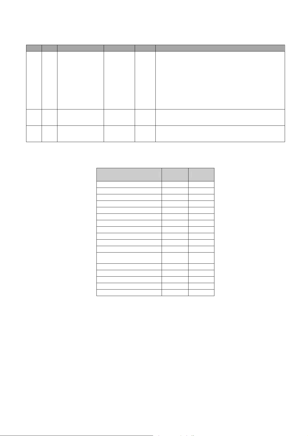
RSW setting
PC ±0 8 Pc
+1 +1 9 9
+2 +2 10 10
+3 +3 11 11
+4 +4 12 12
+5 +5 13 13
+6 +6 14 14
+7 +7 15 15
- ±0 8 8
-7 -7 1 1
-6 -6 2 2
-5 -5 3 3
-4 -4 4 4
-3 -3 5 5
-2 -2 6 6
-1 -1 7 7
The stiffness cor-
rection
Stiffness after
*1 The setting value is 0 that the arrow of rotary switch upward direction. The value is increased
while the arrow is turned by clockwise direction.
Example)Pr0.03=8
correction
LED Display
Parameter Pr0.03
is changed
Possible
Impossible
Motor Business Unit, Appliances Company, Panasonic Corporation
№SR-ZSV00039 - 11 -
All di
s
play
time stiffness in
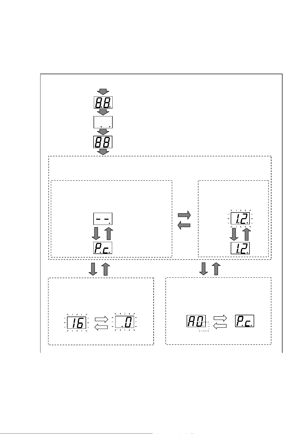
3-2 7 segment LED
At power-up after displaying the check pattern, perform the following normal display.
If you operate the front RSW will show the real-time stiffness value of RSW after adjustment for the front.
However, when an alarm occurs when an alert will display a warning code, the alarm code (main + sub)。
Control power ON
Dot display
[88] display
<Normal >
Priority display of PANATERM and panel RSW is decided by the vaule of RSW.
The display of right dot means main power OK. The diplay of left dot means motor electrified.
<PANATERM priority indicate(RSW=0)>
Servo on/off state is displayed by character。
Set the stiffness by using computer(PANATERM).
Panel RSW
operate
Panel RSW priority indicate (RSW≠0)
LED displays a real-
algorism after adjustment for the
RSW. It can not be set by computer.
Servo-off state
[--]
Servo-on command
Servo-on state
[Pc]
Alarm occur
Decimal indicate:
(right dot:main power OK)
Servo-off command
(riht dot:main power OK)
(left dot:motor electrified)
Alarm clear
< Alarm>
The main code and sub-code(+left dot) of alarm
code(algorism) display alternantly.
(For example:overload)
Main code
Sub-code
(+left dot)
RSW operating
RSW=0
confirm(2s)
Warning occur
RSW except 0
confirm(2s)
RSW confirm
latch:settle problem+alarm clear
No latch:settle problem
Panel RSW
operate
< Warning >
Warning code(hex) and normal state display
alternantly. Left dot flash while warning occur.
(For example:overload)
Warning code(about 2s)
Left dot flash
Normal(about 4s)
Motor Business Unit, Appliances Company, Panasonic Corporation
№SR-ZSV00039 - 12 -
4.Basic function
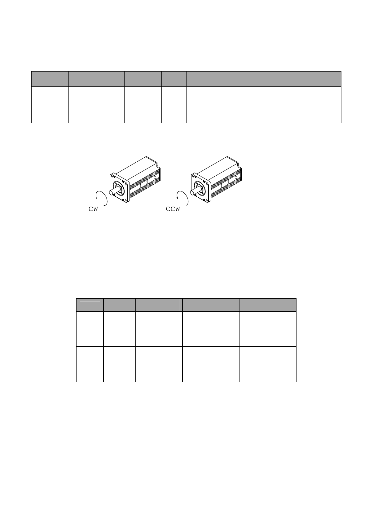
4-1 Setting Rotational Direction
The rotation direction of the motor to the directions of position command can be switched.
■Related parameters
Cate-
gory
0 0
No.
Parameter
Rotational
direction setup
As the direction of motor rotation, clockwise as seen from the shaft end to the load is defined as CW and
counterclockwise as CCW
The positive or negative direction referred to in this document displays the direction as specified with this parameter.
The table below shows the relationships with positive overtravel limit and negative overtravel limit as examples.
Pr0.00
0 Positive CW Enabled
0 Negative CCW
1 Positive CCW Enabled
1 Negative CW
Command
direction
Setup range
0~1
Direction of
motor rotation
Unit Function
Specifies the relationship between the commanded direction and the
-
direction of rotation of the motor.
0 : CW motor rotation for positive direction command
1 : CCW motor rotation for positive direction command
Positive overtravel
limit
Negative overtravel
limit
Enabled
Enabled
Motor Business Unit, Appliances Company, Panasonic Corporation
№SR-ZSV00039 - 13 -
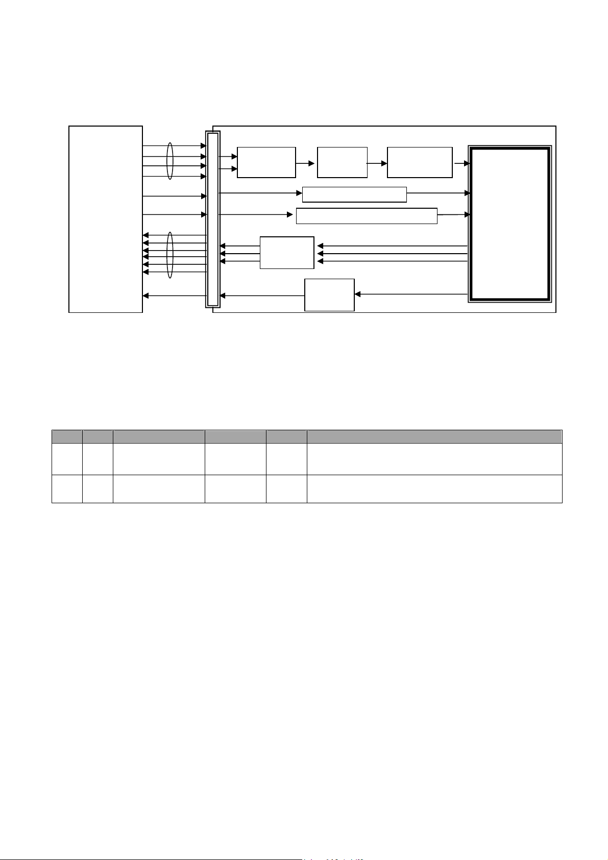
Pulse output
4-2 Position control
Position control is performed based on a position command (pulse train) input from the controller. This sec-
tion describes basic settings for position control.
Controller Servo drive
Position
command
(pulse train)
CL input
INH input
Command
pulse input
section
Command
scaling
function
Counter clear function
Command pulse inhibition function
Position command filter
function
Position con-
trol section
Pulse regeneration function
INP
Output
INP output function
4-2-1 Command Pulse Input
The input of position command (pulse train) use PULS1,PULS2,SIGN1,SIGN2.
Three command pulse formats are supported: 2-phase pulse, positive pulse train/negative pulse train and pulse
train + sign. The pulse format must be selected out of the three and the pulse counting direction must be specified
according to the specifications of the controller and equipment installation condition.
■Related parameters
Category
0
0
No.
6
*
7
*
Command pulse
rotational direction
Command pulse input
mode setup
Parameter
setup
Setup range
01
03
Unit Function
Specifies the counting direction for command pulse input.
See the table on the following page for the details.
Specifies the counting mode for command pulse input.
See the table on the following page for the details.
Motor Business Unit, Appliances Company, Panasonic Corporation
№SR-ZSV00039 - 14 -
t1
t1
t1 t1 t1 t1 t1
t1
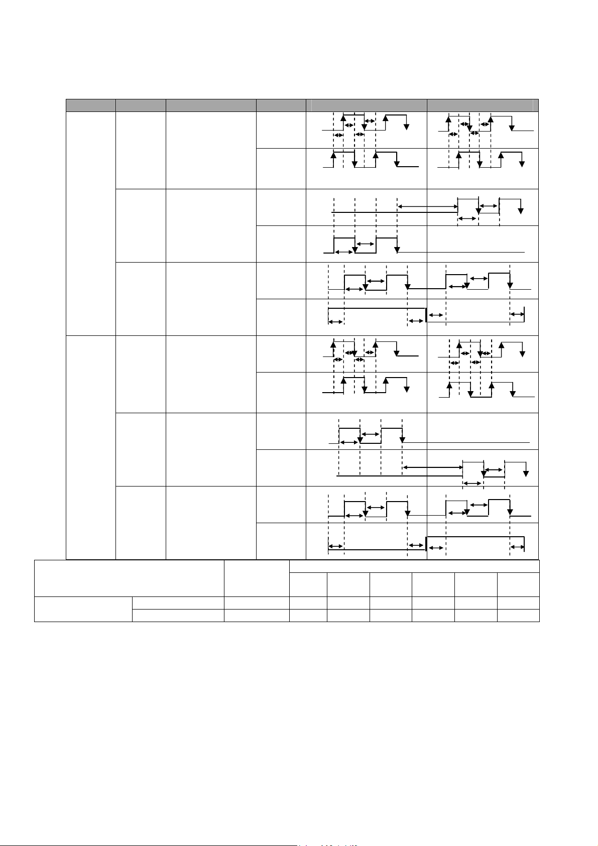
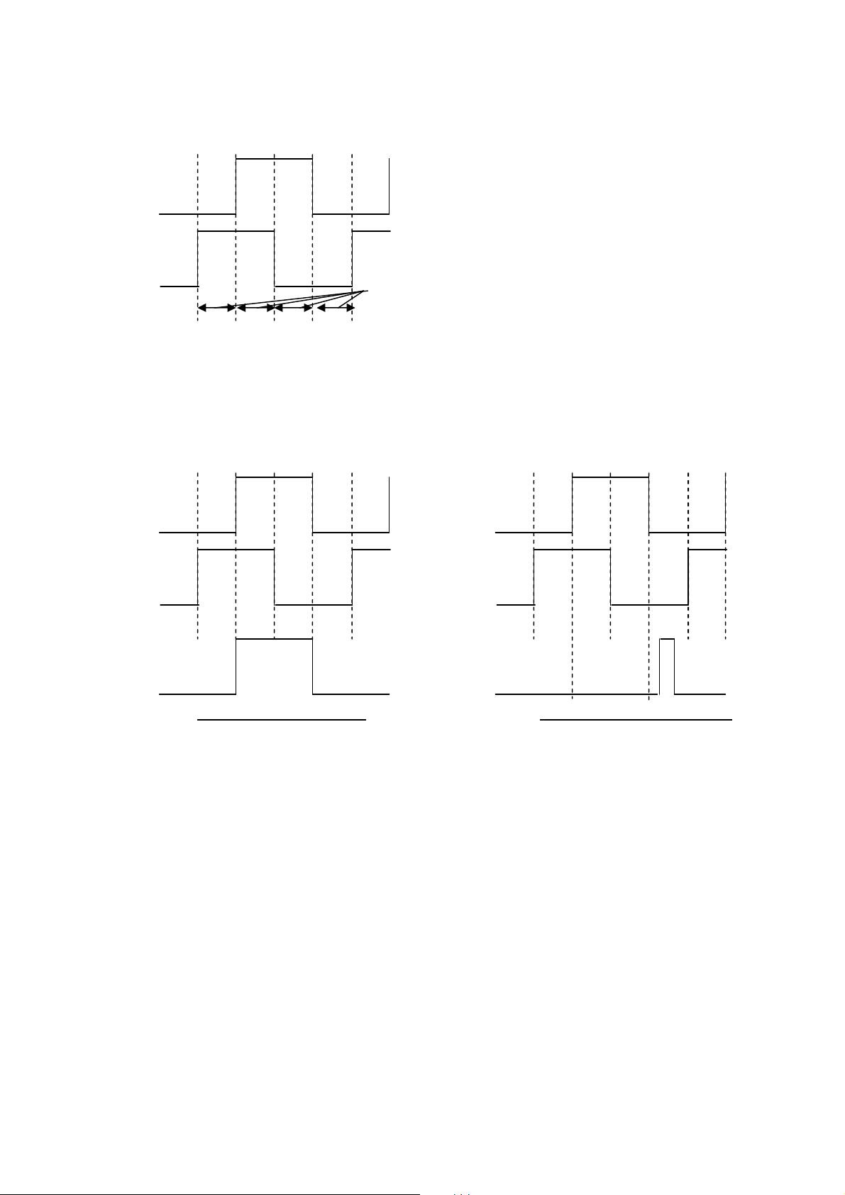
The following table shows the combinations of Pr0.06 "Command pulse rotational direction setup" and Pr0.07
"Command pulse input mode setup"
Pulses are counted at the edges with arrows in the table.
Pr0.06 Pr0.07 Command pulse Signal Positive command Negative command
t1
t1
Phase B delayed by 90 deg from
t2
T4
Phase B advanced by 90 deg from
t2
t4
t6
0
1
PULS/SIGN signal
PULS1, 2, SIGN1, 2
t2
t1
phase A
t2
t3
0
or
2
1
2-phase pulse with
90 difference
(Phase A + Phase B)
Positive pulse train +
Negative pulse train
PULS
SIGN
PULS
SIGN
Phase A
t1
Phase B
Phase B advanced by 90 deg from
T5
T4
H
t6
t6
3 Pulse train + Sign
PULS
SIGN
t6
t2
t1
A
t2
t3
0
or
2
1
2-phase pulse with
90 difference
(Phase A + Phase B)
Positive pulse train +
Negative pulse train
PULS
SIGN
Phase A
t1
Phase B
Phase B delayed by 90 deg from phase
PULS
SIGN
t5
PULS
3 Pulse train + Sign
SIGN
t4
L
t6 t6
Max. allow-
able input
frequency
t1
Minimum required time width [μs]
t2 t3 t4 t5 t6
Line driver 500 kpps 2 1 1 1 1 1
Open collector 200 kpps 5 2.5 2.5 2.5 2.5 2.5
t1
t1
phase A
t2
T5
L
phase A
t5
H
t6
t2
t6
Motor Business Unit, Appliances Company, Panasonic Corporation
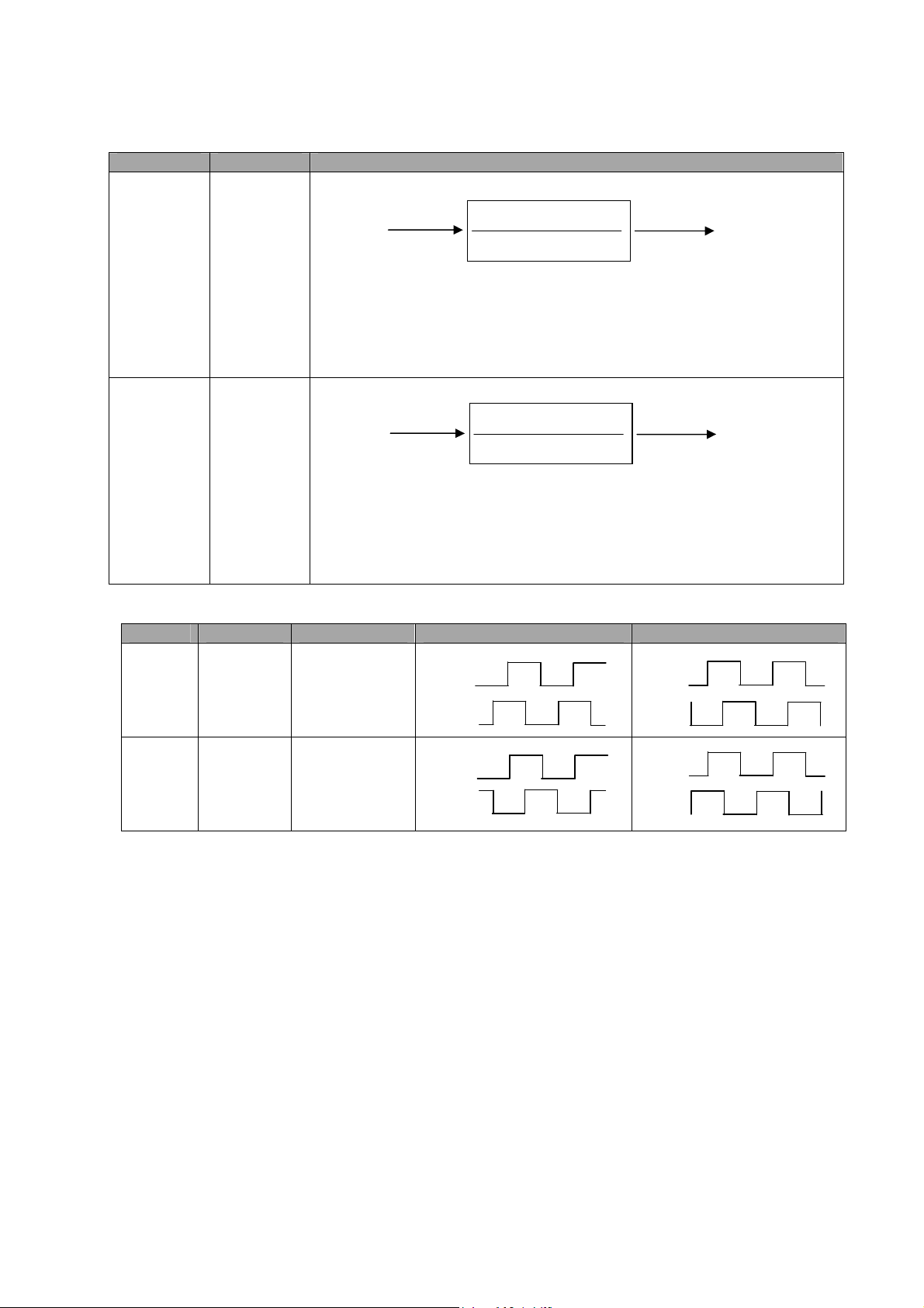
4-2-2 Command Scaling (Electronic Gear)
This function multiplies a pulse command value input from the controller by the specified scaling factor to use as a posi-
tion command to the position control section. Using this function allows arbitrary setting of the motor revolution and distance per unit input command pulse and increase of a command pulse frequency when the required motor speed cannot be
obtained due to the limit to the controller pulse output capability.
Related parameters
Category
0 08
0 09
0 10
No.
Parameter
Command pulse counts
per one motor
revolution
1st numerator of
electronic gear
Denominator of
electronic gear
Setup range
0
1048576
0
1073741824
1
1073741824
Unit
pulse
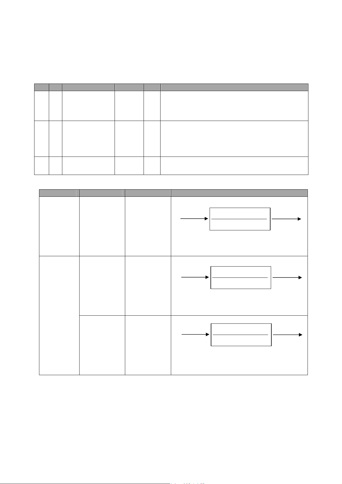
The relationships between Pr0.08, 0.09, and 0.10 in position control
Pr0.08 Pr0.09 Pr0.10 Command scaling
11048576
(No effect)
0
(No effect)
11073741824
0
11073741824 11073741824
№SR-ZSV00039 - 15 -
Function
Specifies the command pulse count corresponding to one revolution
of the motor.
When this setting is 0, Pr0.09 "1st numerator of electronic gear" and
Pr0.10 "Denominator of electronic gear" are valid.
This setting is invalid in full-closed control.
Specifies the numerator for scaling for a command pulse input.
Valid when Pr0.08 "Command pulse counts per one motor revolution"
is 0 or in full-closed control.
When this parameter is set to 0, the encoder resolution is set to the
numerator for position control, and for full-closed control, the
command scaling ratio becomes 1:1.
Specifies the denominator for scaling for a command pulse input.
Valid when Pr0.08 "Command pulse counts per one motor revolution"
is 0 or in full-closed control.
Command
pulse input
Encoder resolution *1
[Set value of Pr0.08]
Position
command
* The process shown in the above diagram is executed in
accordance with the set value of Pr0.08, regardless of settings of Pr0.09 and Pr0.10.
Command
pulse input
Encoder resolution *1
[Set value of Pr0.10]
Position
command
* When the set value of both Pr0.08 and Pr0.09 is 0, the
process shown in the above diagram is executed in accordance with the set value of Pr0.10.
Command
pulse input
* When the set value of Pr0.08 is 0 and that of Pr0.09 is not 0,
the process shown in the above diagram is executed in accordance with the set values of Pr0.09 and Pr0.10.
[Set value of Pr0.09]
[Set value of Pr0.10]
Position
command
Motor Business Unit, Appliances Company, Panasonic Corporation
№SR-ZSV00039 - 16 -
Velocity
Vc0.632
Vc0.368
4-2-3 Position Command Filter
A command filter can be specified to smooth a position command after scaling (electric gear).
Related parameters
Category
2 22
2 23
No.
Parameter
Position command
smoothing filter
Position command FIR
filter
Setup
range
010000 0.1 ms
010000 0.1 ms
Unit
Function
Specifies the first order filter time constant for a position command.
Specifies the FIR filter time constant for a position command.
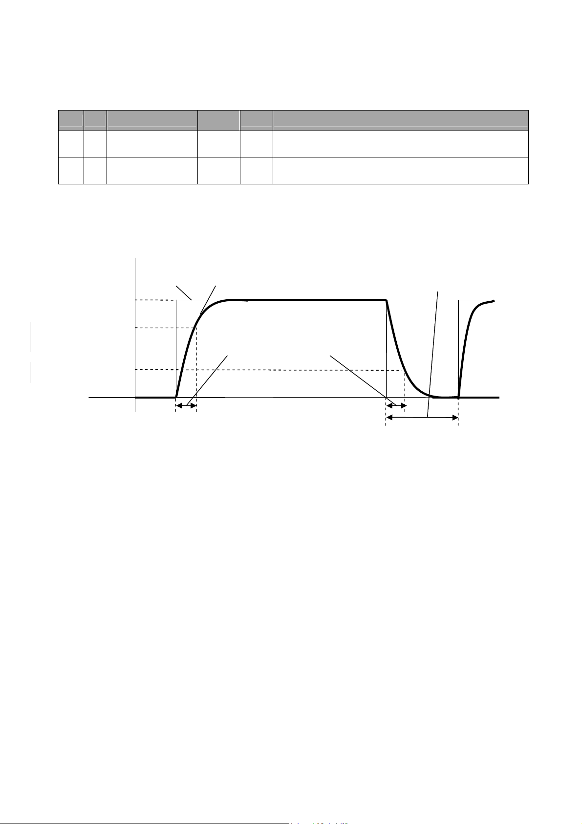
Pr2.22 "Position command smoothing filter"
Specifies the first order filter time constant for a square wave command with a target velocity of Vc as shown in the
figure below.
[r/min]
Position command before
filtering
Position command after filtering
Waiting time for swiching filter *2
Vc
Positional command smoothing
*1
filter Position command
smoothing filter setting time
[ms]
(Pn2Pr2.22×0.1 ms)
*1
Time
*1 Actual filter time constant contains absolute error of 0.4 ms maximum when the set value multiplied by 0.1 ms is less than
100 ms and relative error of 0.2% maximum when the set value multiplied by 0.1 ms is 20 ms or greater.
*2 Pr2.22 " Positional command smoothing filter " is switched when "in-position" is being output and when a command whose
command pulse per time (0.166 ms) changes from 0 to any state except 0 is rising.
Specifically when filter time constant is decreased and the in-position range is increased, the motor may temporarily rotates at
a faster speed than the command speed if accumulated pulses—an area acquired by integrating the difference between the position command before filtering and the position command after filtering by time—are left in the filter at the point above. This
is because accumulated pulses are rapidly cleared immediately after the switching and the motor goes back to the initial position. Use caution.
*3 There is a delay until the change in Pr2.22 " Positional command smoothing filter " is applied to internal calculation. If the switching
timing described in *2 comes during the delay, the change may be suspen
Motor Business Unit, Appliances Company, Panasonic Corporation
№SR-ZSV00039 - 17 -
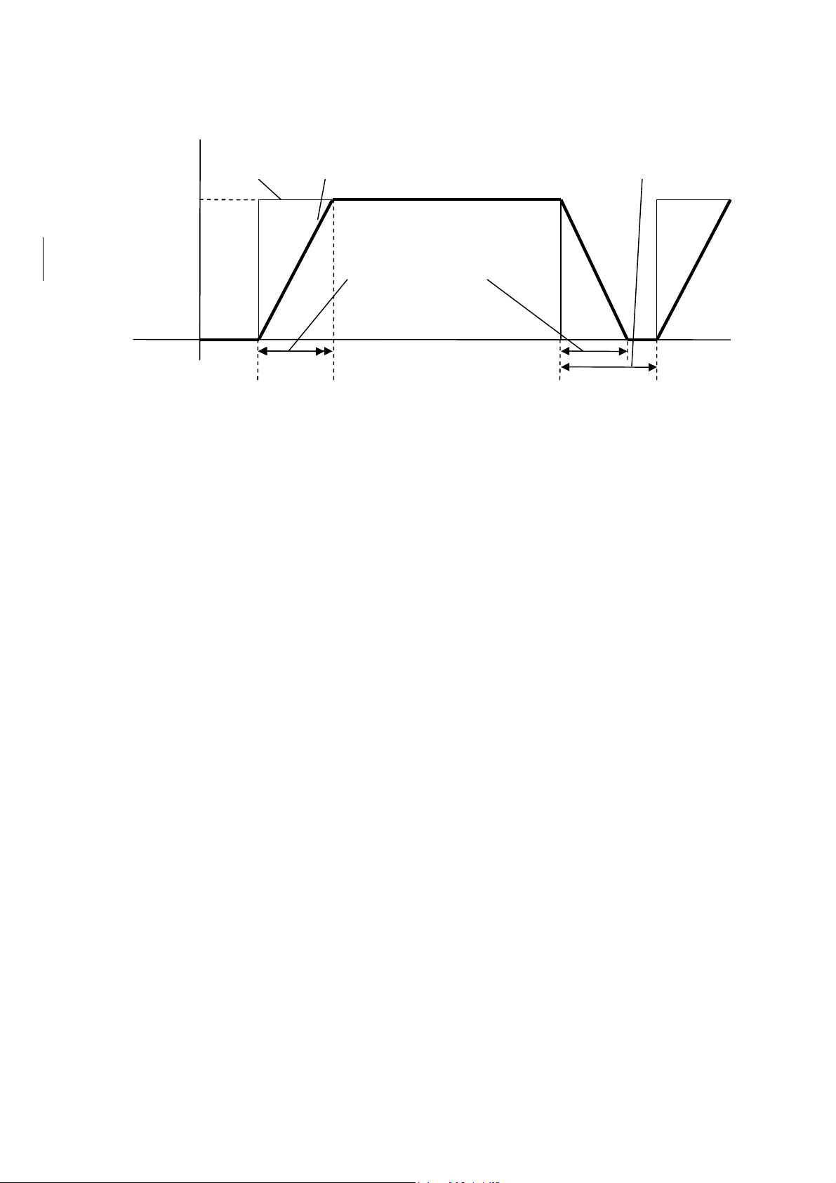
Pr2.23 "Position command FIR filter"
Specifies the time required to reach Vc for a square wave command with a target velocity of Vc as shown in the figure
below.
Velocity
[r/min]
Position command before filtering
Position command after filtering
Waiting time for swiching filter *2
Vc
Position command FIR filter
setting time [ms]
(Pn2Pr2.230.1 ms) *1
Time
*1 Actual average travel times contains absolute error of 0.2 ms maximum when the set value multiplied by 0.1 ms is less than
10 ms and relative error of 1.6% maximum when the set value multiplied by 0.1 ms is 10 ms or greater.
*2 Before changing Pr2.23 "Position command FIR filter," stop the command pulse, and wait until the time for filter switching
passes. The time for filter switching is as follows: the set value 0.1 ms + 0.25 ms in the range of 10 ms or smaller, and the
set value 0.1 ms 1.05 ms in the range of 10 ms or greater. When changing Pr2.23 "Position command FIR filter" during
inputting a command pulse, the change is not updated immediately. It is updated when no command pulse is present during
the time for filter switching.
*3 There is a delay until the change in Pr2.23 "Position command FIR filter" is applied to internal calculation. If the switching
timing described in *2 comes during the delay, the change may be suspended.
Motor Business Unit, Appliances Company, Panasonic Corporation

№SR-ZSV00039 - 18 -
Output pulse counts per
4-2-4 Pulse Regeneration
A distance can be transmitted from the servo drive as phase A and phase B pulses signal to the controller. If the
output source is an encoder, the phase Z signal is output one time per rotation of the motor.
■Related parameters
Category
0 11
0 12
5 03
5 33
No.
one motor revolution
Reversal of pulse
output logic
Denominator of pulse
output division
Pulse regenerative
output limit setup
Parameter
Setup range
1262144 P/r
03
0262144
01
Unit Function
Specifies the output pulse resolution as the output pulse count per
rotation for OA and OB. Accordingly, if the pulse count has been
multiplied by 4, the equation below applies.
Output pulse resolution per rotation = Set value of Pr0.11 4
Specifies the logic of the pulse output phase B signal and the output
source. Reversing the phase B pulse logic allows the phase
relation of phase B pulse with reference to phase A pulse. In the
full-closed control mode, an encoder or external scale can be chosen
as the output source. The output source must be an encoder in
other than full-closed control modes.
If the output pulse counts per one motor revolution is not an integer,
set "Denominator of pulse output division" to any value except 0.
It is also set using a divider ratio with Pr0.11 as the numerator and
Pr5.03 as the denominator. Accordingly, if the pulse count has
been multiplied by 4, the equation below applies.
Output pulse resolution per rotation
= (Set value of Pr0.11 / Set value of Pr5.03) Encoder resolution
Set the error detection function (Err28.0 "Limit of pulse replay error
protection") as valid or invalid.
0: Invalid 1: Valid
Motor Business Unit, Appliances Company, Panasonic Corporation
№SR-ZSV00039 - 19 -
PH A PH B
PH A PH A PH A PH B
PH B
PH B
The following table shows combinations of Pr0.11 "Output pulse counts per one motor revolution" and Pr5.03 "Denomi-
nator of pulse output division".
Pr0.11 Pr5.03
1~262144 0
Encoder pulse
[pulse]
* When Pr5.03 is set as 0, the process shown above is executed in accordance with the set
value of Pr0.11. Accordingly, each of OA and OB of pulse regeneration output will be
identical to the number of pulses set in Pr0.11. The output pulse resolution will not be
identical to the encoder pulse resolution or greater.
Pulse regeneration output processing
[When the output source is the encoder]
[Set value of Pr0.11] 4
Encoder resolution
Output pulse
[pulse]
Encoder FB pulse
[pulse]
[Set value of Pr0.11]
[Set value of Pr5.03]
Output pulse
[pulse]
1~262144 1~262144
* When Pr5.03 ≠ 0, the process above takes place based on the Pr0.11 and Pr5.03
settings, which allows applications where the pulse count per rotation of the pulse regeneration output OA and OB is not an integer.
Note that when the pulse output resolution per rotation is not a multiple of 4, output of
phase Z may not be synchronous with phase A, resulting in a smaller pulse width. The
output pulse resolution will not be identical to the encoder pulse resolution or greater.
Details of Pr0.12 "Reversal of pulse output logic" are shown below.
Pr0.12 Ph B logic Output source For positive direction For negative direction
0
1
Non-reversed
Encoder
Reverse Encoder
*Please do not set setting 2 and 3.
Motor Business Unit, Appliances Company, Panasonic Corporation
№SR-ZSV00039 - 20 -
0.25
■Notes on pulse regeneration function
The maximum output frequency of pulse regeneration output is 4 Mpps (after multiplying by 4). Operation at a
speed exceeding this may cause faulty functioning of regeneration leading to displacement.
PH A
PH B
By Pr5.33 "Pulse regenerative output limit setup", Err28.0 "Limit of pulse replay error protection" can be issued
when reaching the limit of pulse regeneration. Note that this error message is issued by detecting the output limit
of pulse regeneration, not using the maximum output frequency. The error message may be issued when frequency jumps instantaneously, depending on the rotational state of the motor such as rotational fluctuation.
・When the output source is an encoder and the pulse output resolution per rotation is not a multiple of 4, phase Z
may not be synchronous with phase A, leading to a smaller pulse width.
PH A
PH B
PH Z
・When an incremental encoder is used, the first phase Z signal after power-up may not agree with the pulse width as
shown above. When using a phase Z signal, operate the motor by at least one rotation after power-up, make sure
that the phase Z signal has been regenerated once and use the second or later phase Z signal.
Scaling factor: multiple of 4
* If Pr5.03 = 0 and output resolution is specified with Pr0.11, factor is always a multiple of 4.
μs min
PH A
PH B
PH Z
* Not in sync with ph A
Scaling factor: not multiple of 4
Motor Business Unit, Appliances Company, Panasonic Corporation
 Loading...