

Page 1
Instruction Manual
AC Servo Motor & Driver
MINAS E-series
Thank you very much for buying Panasonic AC Servo Motor & Driver, MINAS E-series.
Before using this driver, please read this manual especially refer the safty precautions (page 8 to 11) to ensure
proper use.
Then, keep this manual for your future use.
Page 2

Contents
[Before Use] Page
Safety Precautions ................................................................................................ 8
Maintenance/Inspections .................................................................................... 12
Introduction ......................................................................................................... 14
General ....................................................................................................................................................14
After Opening the Package......................................................................................................................14
Model of Driver ........................................................................................................................................ 14
Model of Motor ......................................................................................................................................... 15
Check the Combination of Driver and Motor............................................................................................15
Parts Description ................................................................................................. 16
Driver ....................................................................................................................................................... 16
Motor........................................................................................................................................................16
Console....................................................................................................................................................17
Installation ........................................................................................................... 18
Driver ....................................................................................................................................................... 18
Motor........................................................................................................................................................20
Console....................................................................................................................................................22
[Preparations] Page
System Configuration and Wiring......................................................................24
General Wiring Diagram .......................................................................................................................... 24
List of Driver and Compatible Peripheral Equipment ............................................................................... 26
Wiring of Connectors CN X1 and X3 (Wiring of Main Circuits) ................................................................ 27
Wiring of Connector CN X4 (Connection with Encoder) .......................................................................... 29
Wiring of Connector CN X5 (Connection with Host Controller) ............................................................... 30
Wiring of Connector CN X6 (Connection with Personal Computer/Console) .......................................... 31
Timing Chart ........................................................................................................ 32
Holding Brake ...................................................................................................... 35
Dynamic Brake (DB) ............................................................................................ 36
Homing Operation (Precautions) ....................................................................... 38
Setting the Parameters ....................................................................................... 39
Overview of Parameters .......................................................................................................................... 39
How to Set ............................................................................................................................................... 39
Overview of Console................................................................................................................................39
Overview of PANATERM® ........................................................................................................................ 39
How to Connect ....................................................................................................................................... 40
Parameter Groups and Listing ................................................................................................................. 41
Using the Console ............................................................................................... 47
Using the Console ................................................................................................................................... 47
The initial State of the Display (7-segment LED) ..................................................................................... 47
Structure of Each Mode ...........................................................................................................................48
Monitoring Mode ......................................................................................................................................51
2
Page 3

Parameter Setting Mode .......................................................................................................................... 57
Before Use
Preparations
Connections and
Settings in Position
Control Mode
Connections and
Settings in Internal
Velocity Control Mode
Adjustment
Trouble Case
Reference
Normal Auto Gain Tuning Mode............................................................................................................... 58
Alarm Clear .............................................................................................................................................. 59
Test Run (JOG) ........................................................................................................................................ 60
Test Run Procedures ...............................................................................................................................61
Copy Function..........................................................................................................................................62
[Connections and Settings in Position Control Mode]
Page
Control Block Diagram in Position Control Mode ............................................ 66
Wiring to Connector CN X5 ................................................................................ 67
Example of Wiring in Position Control Mode ........................................................................................... 67
Interface Circuit........................................................................................................................................68
Input Signal and Pin No. of Connector CN X5 ......................................................................................... 70
Output Signal and Pin No. of Connector CN X5 ...................................................................................... 72
Example of Connection to a Host Controller............................................................................................73
Test Run in Position Control Mode .................................................................... 82
Inspection prior to Test Run ..................................................................................................................... 82
Test Run with Connector CN X5 Connected............................................................................................ 82
Real time Auto Gain Tuning................................................................................86
Outline ..................................................................................................................................................... 86
Scope.......................................................................................................................................................86
Operating Instruction ............................................................................................................................... 86
Adaptive Filter .......................................................................................................................................... 87
Parameters to be Set Automatically......................................................................................................... 87
Cautions...................................................................................................................................................87
[Connections and Settings in Internal Velocity Control Mode]
Parameter Setting ................................................................................................ 88
Parameter for Selection of Functions ...................................................................................................... 88
Parameters for Adjustment of Time Constants of Gains/Filters ............................................................... 91
Parameters for Auto Gain Tuning ............................................................................................................ 92
Parameters for Adjustment (Related to Second Gain Switching Function) ............................................. 94
Parameters for Position Control...............................................................................................................95
Parameters for Internal Velocity Control .................................................................................................. 98
Parameters for Torque Limits................................................................................................................... 99
Parameters for Sequences ...................................................................................................................... 99
Page
Control Block Diagram in Internal Velocity Control Mode ............................ 104
Wiring to Connector CN X5 .............................................................................. 105
Example of Wiring to Connector CN X5 ................................................................................................ 105
Interface Circuit...................................................................................................................................... 106
Input Signal and Pin No. of Connector CN X5 ....................................................................................... 107
Output Signal and Pin No. of Connector CN X5 .................................................................................... 109
Test Run in Internal Velocity Control Mode .................................................... 110
3
Page 4

Inspection prior to Test Run ................................................................................................................... 110
Test Run with Connector CN X5 Connected ......................................................................................... . 111
Real time Auto Gain Tuning.............................................................................. 114
Outline ................................................................................................................................................... 114
Scope..................................................................................................................................................... 114
Operating Instruction ............................................................................................................................. 114
Parameters to be Set Automatically....................................................................................................... 115
Cautions................................................................................................................................................. 115
Parameter Setting .............................................................................................. 116
Parameter for Selection of Functions .................................................................................................... 116
Parameters for Adjustment of Time Constants of Gains/Filters ............................................................. 119
Parameters for Auto Gain Tuning .......................................................................................................... 120
Parameters for Position Control............................................................................................................. 121
Parameters for Internal Velocity Control ................................................................................................ 122
Parameters for Torque Limits ................................................................................................................. 123
Parameters for Sequences .................................................................................................................... 123
[Adjustment] Page
Gain Adjustment ................................................................................................ 128
Objective of Gain Adjustment ................................................................................................................ 128
Types of Gain Adjustment ...................................................................................................................... 128
Procedures of Gain Adjustment ............................................................................................................. 129
Real time Auto Gain Tuning.............................................................................. 130
Normal Auto Gain Tuning ................................................................................. 132
Cancellation of the Automatic Gain Tuning .................................................... 135
Manual Gain Tuning (Basic) ............................................................................. 136
Manual Gain Tuning (Application) ................................................................... 138
Gain Switching Function ........................................................................................................................138
To Reduce Mechanical Resonance ....................................................................................................... 140
Anti-Vibration Control............................................................................................................................. 142
4
Page 5

Before Use
Preparations
Connections and
Settings in Position
Control Mode
Connections and
Settings in Internal
Velocity Control Mode
Adjustment
[Trouble Case] Page
Reference
Trouble Case
Protective Functions ......................................................................................... 144
What are Protective Functions?............................................................................................................. 144
Details of Protective Functions .............................................................................................................. 145
Software limit function............................................................................................................................ 148
Troubleshooting ................................................................................................ 150
[Reference] Page
Outline of “PANATERM®”, Setup Support Software ............................................................................... 156
Communications ....................................................................................................................................158
Description on Dividing/Multiplier Ratio ................................................................................................. 178
Conformance to EC Directives/UL Standards ....................................................................................... 180
Optional Parts ........................................................................................................................................184
Recommended Parts .............................................................................................................................192
Dimensional Outline Drawing (Driver) ................................................................................................... 193
Dimensional Outline Drawing (Motor) .................................................................................................... 194
Allowable Load of Output Shaft ............................................................................................................. 196
Motor Characteristics (S-T Characteristics) ........................................................................................... 197
Servo Motor with Gear ........................................................................................................................... 198
Dimensional Outline Drawing of Motor with Gear .................................................................................. 200
Allowable Load of Output Shaft of Servo Motor with Gear .................................................................... 202
Characteristics of Servo Motor with Gear (S-T Characteristics) ............................................................203
Driver Internal Block Diagram ................................................................................................................ 204
Control Block Diagram ........................................................................................................................... 205
Specifications (Driver/Motor) ................................................................................................................. 206
Hit-and-stop Initialization and Load Pressing Control ............................................................................ 207
Index ......................................................................................................................................................209
Reference .............................................................................................................................................. 214
After-Sale Service (Repair) ........................................................................................................ Back cover
5
Page 6

MEMO
6
Page 7
Before Use
Before Use
Page
Safety Precautions .......................................................... 8
Maintenance/Inspections ............................................. 12
Introduction ................................................................... 14
General ...................................................................................................14
After Opening the Package ..................................................................... 14
Model of Driver ........................................................................................ 14
Model of Motor ........................................................................................15
Check the Combination of Driver and Motor ........................................... 15
Parts Description .......................................................... 16
Driver ......................................................................................................16
Motor ....................................................................................................... 16
Console ................................................................................................... 17
Installation ..................................................................... 18
Driver ......................................................................................................18
Motor ....................................................................................................... 20
Console ................................................................................................... 22
7
Page 8
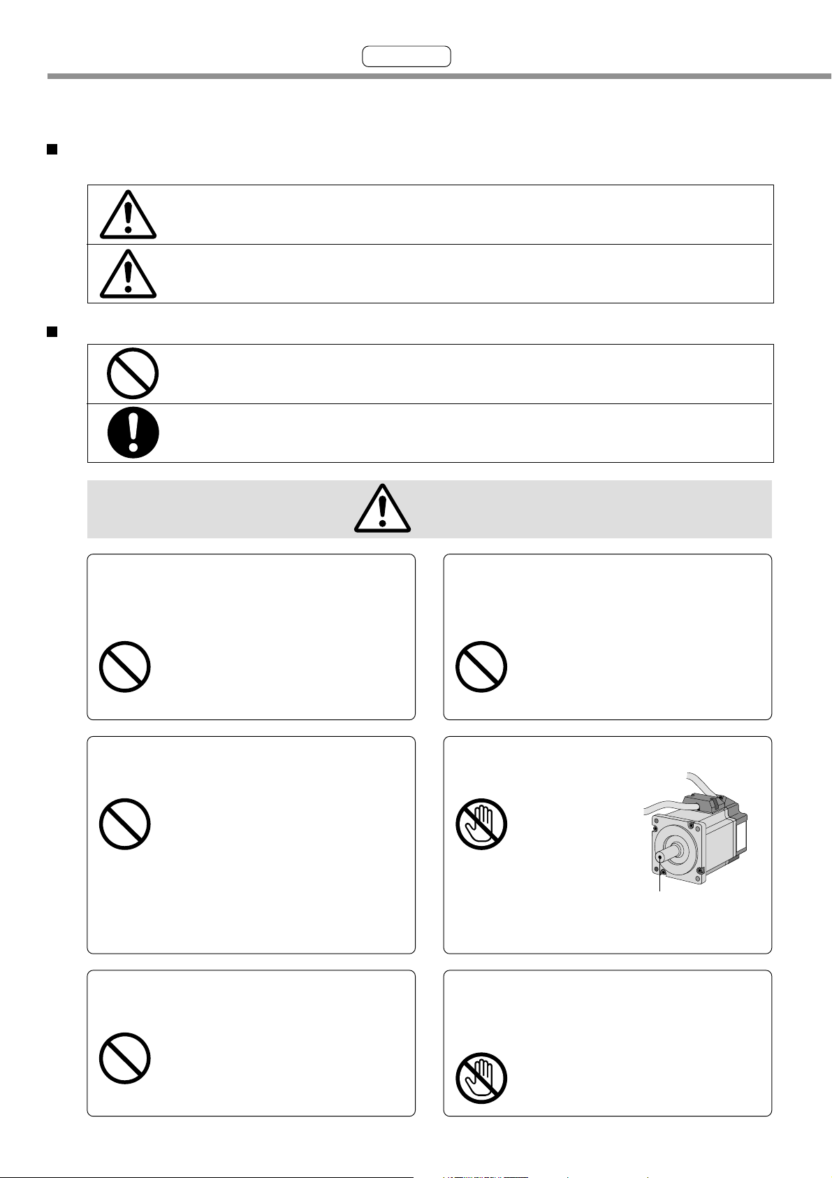
Safety Precautions
See the following precautions in order to avoid damages on machinery and injuries among the
operators and other people during the operation.
The following symbols are used to indicate the degrees of hazard seriousness possibly occurred when
you fail to comply with the safety precautions.
Indicates a potentially hazardous situation, which if not avoided, will result in
DANGER
CAUTION
The following symbols indicate what you must do.
Indicates that the operation is prohibited to do.
Indicates that the operation must be done.
death or serious injury.
Indicates a potentially hazardous situation, which if not avoided, will result in
minor injury or physical damage.
Important
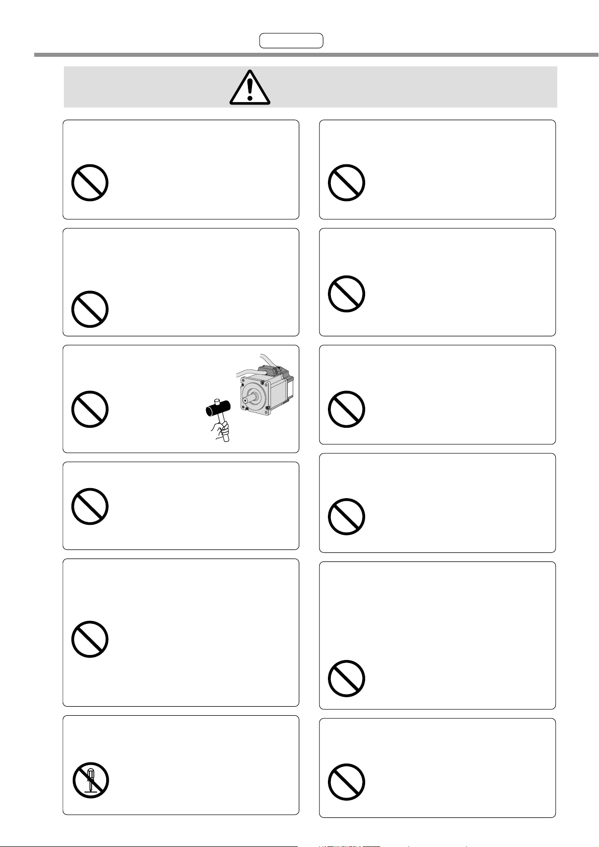
DANGER
Do not subject the product to water,
corrosive or flammable gases, and
combustibles.
The failure could result in
fire.
Do not put your hands in the servo
driver.
The failure could result in
burns, or electric shocks.
Do not expose the cables to sharp
objects, excessive pressing or
pinching forces, and heavy loads.
The failure could result in
electric shocks, damages, or
malfunction.
Do not touch the rotating part of the
motor while operating.
Rotating Part
Do not drive the motor from the
external power.
The failure could result in
fire.
The failure could result in injuries.
Do not touch the motor, driver, and
external regenerative resistor, since
they become hot.
The failure could result in
burns.
8
Page 9
Before Use
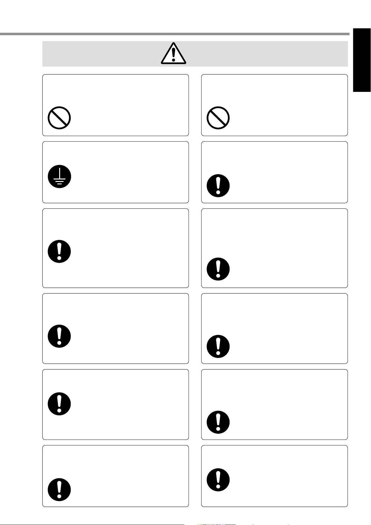
DANGER
[Before Use]
Do not place inflammable matter
near the motor, driver, and
regenerative resistor.
The failure could result in
fire.
Ground the earth of the servo motor
and servo driver.
The failure could result
in electric shocks.
Install an external emergency stop
device to shut down the main power
source in any emergency.
The failure could result in
electric shocks, injuries, fire,
damages or malfunction.
Do not install the console near
sources of heat like the heater, the
resistor, or etc.
The failure could result in
fire or damages.
An over-current protection, earth leakage
breaker, over temperature protecter and
emergency stop device must be installed.
The failure could result in
electric shocks, injuries, or
fire.
Wait at least the time described on the
driver after switching off the power to
allow the capacitors to discharge before
beginning to conduct the transportation,
wiring, and inspection of the driver.
The failure could result in
electric shocks.
Install the product properly to avoid
personal accidents or fire in case of
an earthquake.
The failure could result in
electric shocks, injuries, or
fire.
Make sure to secure the safety after
the earthquake.
The failure could result in
electric shocks, injuries, or
fire.
Attach the motor, driver,
regenerative resistor to
incombustible matter such as metal.
The failure could result in
fire.
Confirm that there is no danger of an
electric shock before beginning to
conduct the transportation, wiring,
and inspection of the motor.
The failure could result in
electric shocks.
Only persons who are trained and qualified to work with or on electrical equipment are permitted to operate or maintain this equipment.
The failure could result in
electric shocks.
Arrange the phase sequense of the
motor and wiring of the encoder.
The failure could result in
injuries, damages, or
malfunction.
9
Page 10
Safety Precautions
CAUTION
Important
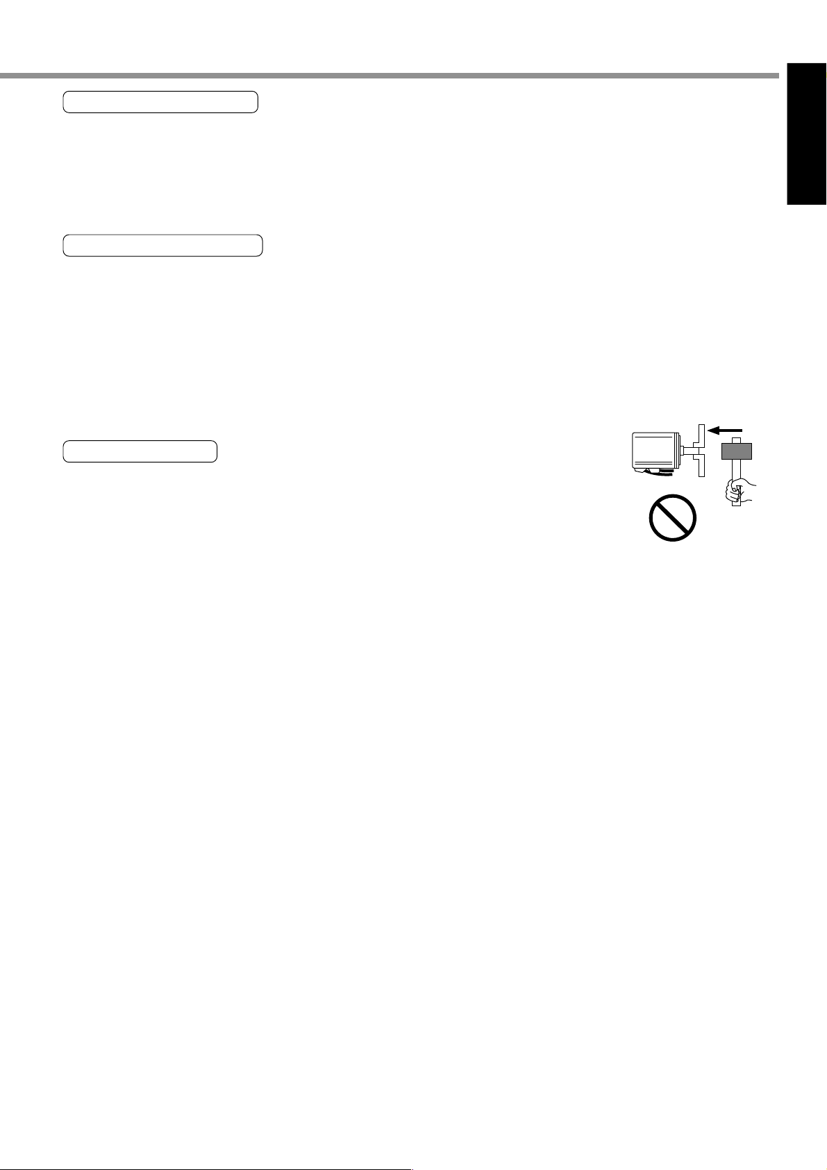
Do not hold the cables or motor
shaft when transporting the motor.
The failure could result in
injuries.
Never start and stop the motor by
magnet contactor which is provide on
the main line.
The failure could result in
damages.
Do not give hard
pressure to the shaft.
The failure
could result
in damages.
Do not block the heat dissipation
hole.
The failure could result in
electric shocks, or fire.
Do not climb or stand on the servo
equipment.
The failure could result in
electric shocks, injuries,
damages, or malfunction.
Do not turn on or off the power
frequently.
The failure could result in
damages.
Do not shock the driver and the motor.
The failure could result in
damages.
Do not use the motor internal brake
for the purpose of controlling speed
of load.
The failure could result in
injuries, or damages.
Do not modify, dismantle or repair
the product.
The failure could result in
Avoid excessive gain adjustments, changes,
or unstable operation of the product.
The failure could result in
injuries.
Do not approach to the equipment
after recovery from the power failure
because they may restart suddenly.
Execute the personal safety setting
on the Equipment after the restart.
The failure could result in
injuries.
Do not pull the motor cable by too
much power.
electric shocks, injuries, or
fire.
The failure could result in
damages.
10
Page 11
Before Use
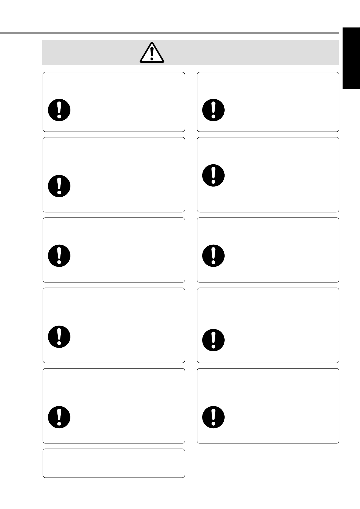
CAUTION
[Before Use]
Use the motor and driver with the
specified combination.
The failure could result in
fire.
Use the eye-bolt of the motor only
when you carry the motor.
Do not use it when you carry the machine.
The failure could result in
injuries, or damages.
Conduct proper installation according
to product weight or rated output.
Make sure that the wirings are
correctly connected.
The failure could result in
electric shocks, or injuries.
Install the driver and the motor in the
specified direction.
The failure could result in
damages.
Use the specified voltage on the
product.
The failure could result in
The failure could result in
injuries, or damages.
Ambient temperature of installed
motor and driver should be under
permittable one.
The failure could result in
damages.
Connect a relay that stops at
emergency stop in series with the
brake control relay.
The failure could result in
injuries, or damages.
electric shocks, injuries, or
fire.
Execute the trial-operations with the
motor fixed and a load unconnected.
Connect a load to the motor after the
successful trial-operations.
The failure could result in
injuries.
If an error occurs, remove the causes
of the error and secure the safety
before restarting the operation.
The failure could result in
injuries.
This product should be treated as an
industrial waste when it is disposed.
11
Page 12

Maintenance/Inspection
• Routine maintenance and inspections are essential for proper and satisfactory operation of the driver
and motor.
Notes to Maintenance/Inspections Personnel
(1) Power-on/off operations should be done by the operators themselves.
(2) For a while after power off, the internal circuits is kept charged at higher voltage. Inspections should be done a
while (about 10 minutes), after the power is turned off and the LED lamp on the panel is extinguished.
(3) When conducting meager test (to measure insulation resistance) on the servo driver, disconnect all the connec-
tions from the driver. Conducting the test as connected would cause trouble of the driver.
Inspection Items and Cycles
Normal (correct) operating conditions:
Ambient temperature: 30˚C (annual average) Load factor: max. 80%
Operating hours: max. 20 hours per day
Daily and periodical inspections should be done per the following instructions.
Type
Daily inspection
Periodical
inspection
<Notes>
If the operating conditions (as stated above) differ, this periodic inspection interval is subject to change.
Cycles
Daily
Every year
Inspection items
• Ambient temperature, humidity, dust, particles, foreign matters, etc.
• Abnormal sound and vibration
• Main circuit voltage
• Odor
• No yarn piece, etc. adhered to the air hole?
• How the driver front and connector are cleaned?
• Each wired cable is damage-free?
• The portions connected with the motors of equipment/plant are free
from loose and center deviation?
• No inclusion of foreign matter at the load side?
• Loosened screws
• Signs of overheat
We make the utmost effort to ensure the quality of our product. However, the product may
operate differently from your settings, due to unexpectedly high exogenous noise/applied
static electricity, or an unforeseen failure in the input power supply, wiring, components, etc.
Hence, we would like to request you to give adequate consideration to the fail-safe design and
assurance of safety within the operable range at the place of operation in your company.
12
Page 13

[Before Use]
Before Use
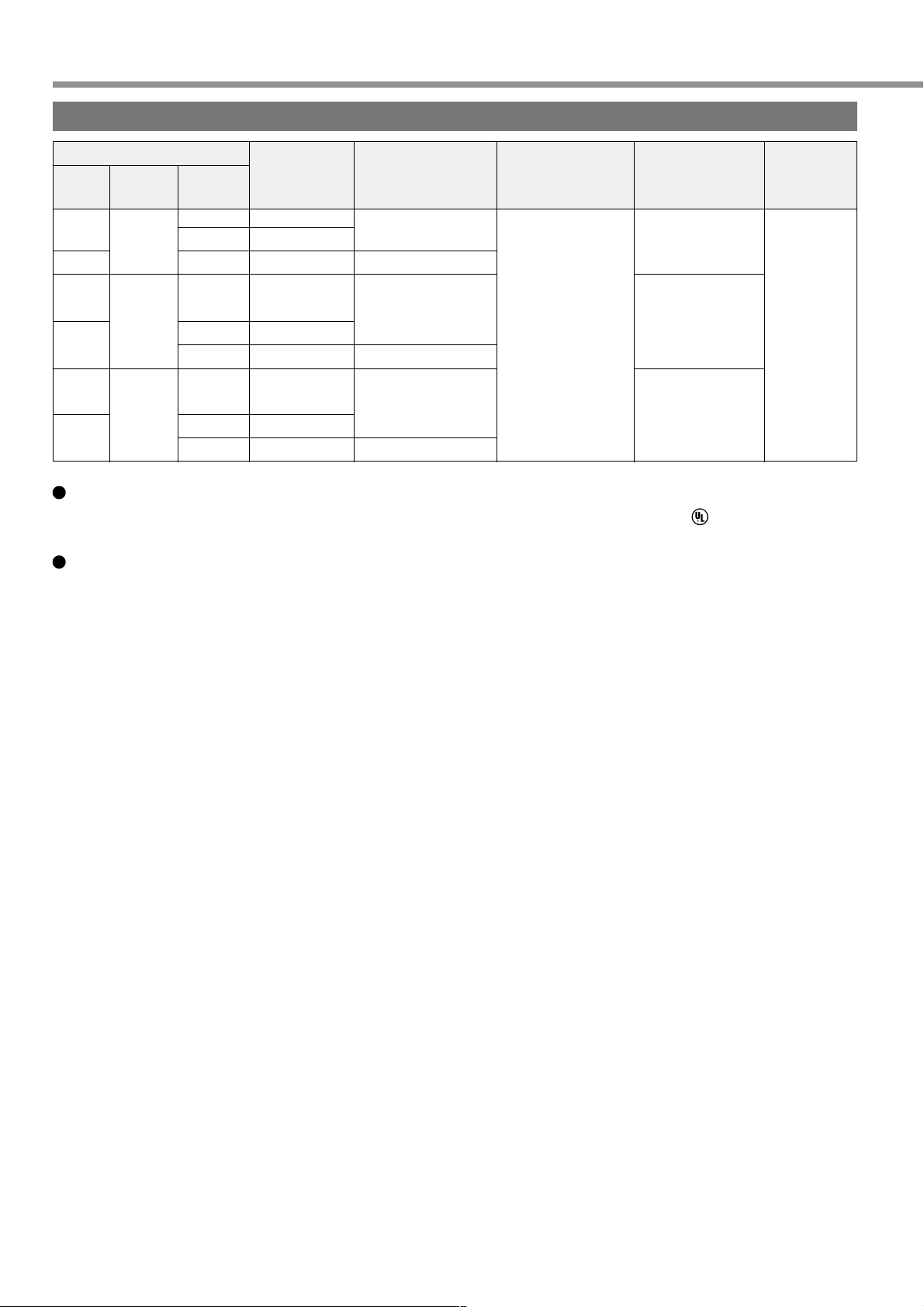
Replacement Guidance
Parts replacement cycles depend on the actual operating conditions and how the equipment has been used.
Defective parts should be replaced or repaired immediately.
Dismantling for inspections or repairs should be done by our
company (or our sales agents).
Prohibited
Equipment
Driver
Motor
Motor with Gear
Part
Smoothing condenser
Aluminum electrolytic
capacitor on the print
board
Rush current
preventive relay
Rush current
preventive resistor
Cooling fan
Bearing
Oil seal
Encoder
Speed reducer
Standard replacement
cycles (hour)
about 5 years
about 5 years
Approx. 100,000 cycles
(The life depends on the
actual operating
conditions.)
Approx. 20,000 cycles
(The life depends on the
actual operating
conditions.)
2 to 3 years
(10,000 to 30,000 hours)
3 to 5 years
(20,000 to 30,000 hours)
5000 hours
3 to 5 years
(20,000 to 30,000 hours)
10,000 hours
Remarks
The replacement cycles shown here
are just only for reference if any part
is found defective regardless of the
standard replacement cycles,
immediately replace it with a new
one.
13
Page 14
Introduction
General
MINAS-E series is a unit of an AC servo motor and driver with downsized capability and performance that are useful
for positioning of a motor whose capacity is small from 50W to 400W.
By adopting 2500 P/r incremental encoder with velocity response frequency of approximately 400 Hz and 5 wires,
we could omit wiring.
The equipment includes real-time auto tuning and enables automatic setting of complicated gain tuning. In addition,
it has a damping control function that provides for stable stop performance and contributes to miniaturization of the
equipment and reduction of tact time.
It supports a console (available as an option) capable of monitoring such as display of rotation speed, parameter
setting, test run (JOG operation), parameter copying, etc., and pursues maximum ease for use.
This document is designed for you to properly and sufficiently use functions of MINAS-E series with such excellent
features.
Cautions
(1) No part or whole of this document may be reproduced in any form or by any means.
(2) Contents of this document are subject to change without notice.
After Opening the Package
• Make sure that the product is what you ordered.
• Check whether the product is damaged.
•
The instruction manual (Safety edition and Extracted edition) is included in a carton box.
If the product is not what you purchase, or it is, or damaged, contact dealer or sales agent.
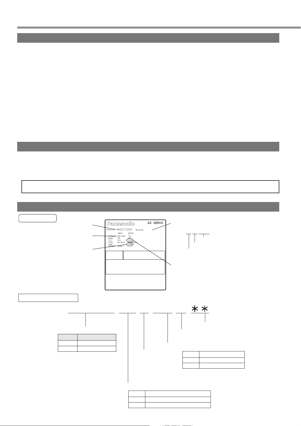
Model of Driver
Name plate
Rated input voltage
Rated motor output
Model Designation
Outer frame symbolic characters
Symbol
MKDE
MLDE
Model
03010001
Serial Number
Ex.:
03010001
Rated output current
MKDET1310 P
1~4 5~6
Frame name
E-Series K frame
E-Series L frame
7 10
Control Mode
P: Position Control
Current rating of current detector
Power supply
1: Single-phase 100 V
2: Single-phase 200 V
3: Three-phase, 200 V
5: Single-phase/Three-phase, 200 V
Symbol
Lot Number
Month of production
Year of production
(Lower 2 digits of AD year)
11~128~9
Special specifications
Current rating of current detector
05
10
5A
10A
Maximum current rating of power element
Symbol
Maximum current rating of power element
T1
T2
14
10A
15A
Page 15
Before Use
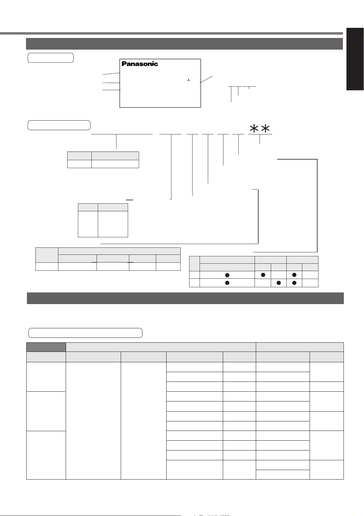
Model of Motor
)
Name plate
Rated output
Rated speed
Type
AC SERVO MOTOR
MODEL No.
MUMA022PIS
INPUT 3flAC
RATED OUTPUT
RATED FREQ.
RATED REV.
200
3000
102
CONT. TORQUE
RATING S1
INS. CLASS B (T V) A (UL)
IP65
V
A1.6
CONNECTION
kW
0.2
SER No.
Hz
r/min
0.64
03010001
Nm
Serial Number
Ex.:
03010001
Lot Number
Month of production
Year of production
(Lower 2 digits of AD year
[Before Use]
Model Designation
MUMA5AZP1S
1~4 5~6
Symbol
MUMA
Table 1a:
Motor rated output
Symbol
5A
01
02
04
Table 1-b: Rotary encoder
Symbol
P
Type
Incremental
Type
Ultra low inertia
Rated output
50W
100W
200W
400W
Specifications
No. of pulses
2500P/r
Rated output
Resolution
10000
Lead wire
5-wire
Check the Combination of Driver and Motor
78910
11~12
Motor structure
Design order
1: Standard
Type of encoder
Power supply
1: 100 V
2: 200 V
Z: 100/200 V common-used
(Limited to 50W only)
Table 1c: Motor structure
Shaft
Center tap on key-wayed shaft end
S
T
Custom specifications
Holding brake
Without
With
Oil seal
Without
With
This driver is designed for use in combination with a motor to be specified by us.
Check a name of series, rated output, voltage specifications and encoder specifications of a motor you wish to use.
Incremental specification 2500 P/r
Power Supply Motor Series Driver Type
Single-phase
100V
Single-phase
200V
MUMA
Ultra low inertia
Three-phase
200V
Rated Speed
3000r/min
<Note> You must not use any other combinations than those listed below:
Applicable Motor Applicable Driver
Motor Type
MUMA5AZP1*
MUMA011P1*
MUMA021P1*
MUMA5AZP1*
MUMA012P1*
MUMA022P1*
MUMA042P1*
MUMA5AZP1*
MUMA012P1*
MUMA022P1*
MUMA042P1*
Rated Output
50W
100W
200W
50W
100W
200W
400W
50W
100W
200W
400W
MKDET1105P
MKDET1110P
MLDET2110P
MKDET1505P
MKDET1505P
MLDET2210P
MLDET2510P
MKDET1505P
MKDET1505P
MKDET1310P
MLDET2310P
MLDET2510P
Driver
Frame
Frame K
Frame L
Frame K
Frame L
Frame K
Frame L
<Remarks>
The marking " * " in Motor Type column of Applicable Motor represents a motor specifications.
15
Page 16
Parts Description
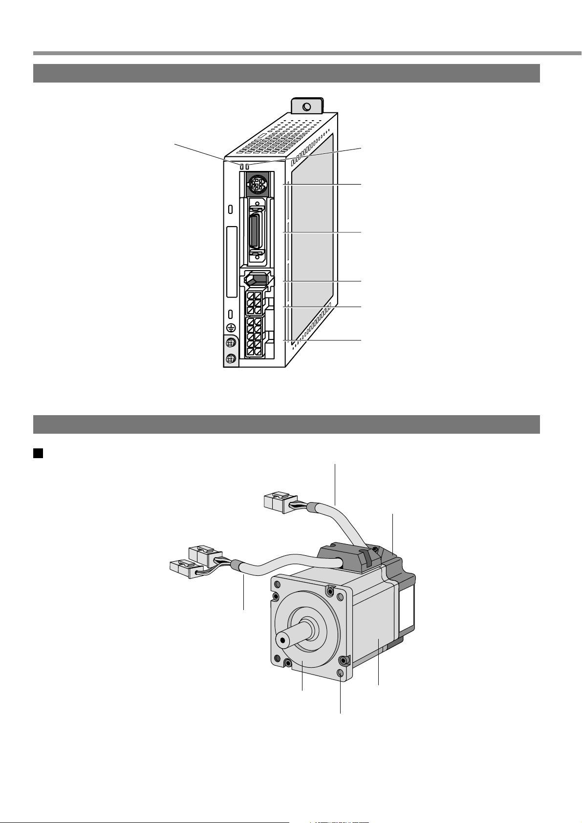
Driver
Motor
Status LED
STATUS
ALM CODE
Alarm Code LED
x
6
Connector for Serial Communications
(X6)
x
5
x
4
x
3
x
1
Interface Connector (X5)
Encoder Connector (X4)
Motor Connector (X3)
Main Power Supply Connector (X1)
MUMA 50W - 400W
Motor Cable
Encoder Cable
Encoder
Flange
Frame
Mounting Holes (in 4 locations)
Example: Super Low Inertia Type (MUMA Series 50W)
<Remarks>
For detailed information on each type, refer to a dimensional outline drawing (Pages 194 to 195) of
Reference edition.
16
Page 17

Before Use
Console
Main body
[Before Use]
Connector
Console main unit
Cable
<Remarks>
The console is optionally available. (Part No.: DV0P3690)
Touch panel
Display, LED (display in 6 digits)
Display of selected Driver ID No. (2 digits)
The value set up on Pr00 (shaft name) is ID No.
Parameter No. (2 digits) is displayed under Parameter Setting
mode.
This is used to shift the digits of data.
This is used to change the data and to execute parameter selection.
The numerical value goes up and down by pressing and .
M
MODE
MINAS
DIGITAL AC SERVO
SHIFT
M
M
O
D
E
S
H
I
F
T
S
S
E
T
Touch panel
Display
(7-segment LED)
S
SET
Setting Button: This is to shift each mode, which was selected by
the mode selector button, to EXECUTE display.
Mode Selector Buttons: These buttons are used to select 6 different modes.
(1) MONITOR mode
(2) PARAMETER SETTING mode
(3) EEPROM WRITE mode
(4) NORMAL AUTO GAIN TUNING mode
(5) AUXI FUNCTION mode
Test run (JOG mode)
Alarm clear
(6) COPING FUNCTION mode
To copy parameters to the console from the servo driver.
To copy parameters to the servo driver from the console.
17
Page 18
Installation
The driver and motor should be properly installed to avoid failures, mechanical damages and injuries.
Driver
Location
(1) Indoors, where the driver is not subjected to rain water and direct sun beams. Note that the driver is not a
waterproof structure.
(2) The place where the driver is not exposed to corrosive atmospheres such as hydrogen sulfide, sulfurous acid,
chlorine, ammonia, sulfur, chlorine gas, sulfuric gas, acid, alkali, salt, etc. and is free from splash of flammable
gas, grinding coolant, oil mist, iron powder, chips, etc.
(3) Place in a well-ventilated, and humid-and dust-free space.
(4) Place in a vibration-free space.
Environmental Conditions
Item
Ambient temperature
Ambient humidity
Lower than 90%RH (free from condensation)
Storage temperature
Storage humidity
Vibration
Lower than 90%RH (free from condensation)
Lower than 5.9 m/s2 (0.6G) at 10 to 60 Hz
Altitude
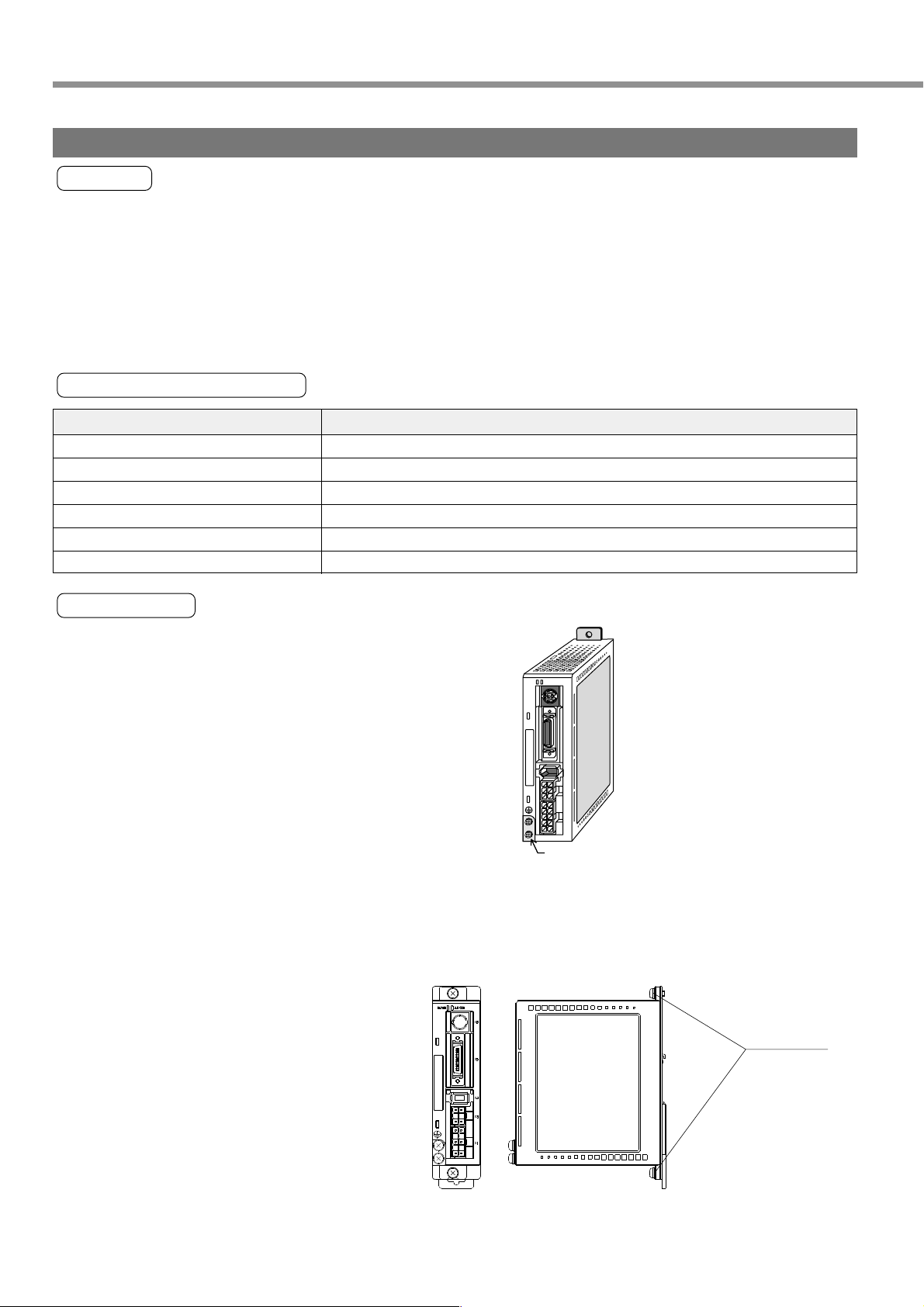
How to Install
(1) Parallel type. Install in vertical position. Reserve a drafting
space around the driver for ventilation.
(2) For the mounting dimensions onto the wall face in the board,
refer to Page 193 of the dimensional outline drawing.
Conditions
0 to 55°C (free from freezing)
-20 to 80°C (free from freezing)
Lower than 1000 m
Base mount type
STATUS
ALM CODE
x
6
x
5
x
4
x
3
x
1
Earth connection (M4 screw) tightening
torque shall not exceed 0.39 - 0.59 N•m
(3) Installing to DIN Rail
Install the main body of the driver by using optionally available DV0P3811 (see an “optional” DIN rail mounting unit
on page 190 of Reference edition) and screws (M4 x length 8, pan-head machine screws) supplied with the
option.
Ancillary Screws
(M4 x Length 8 )
DIN rail mounting unit attached to the driver
18
Page 19
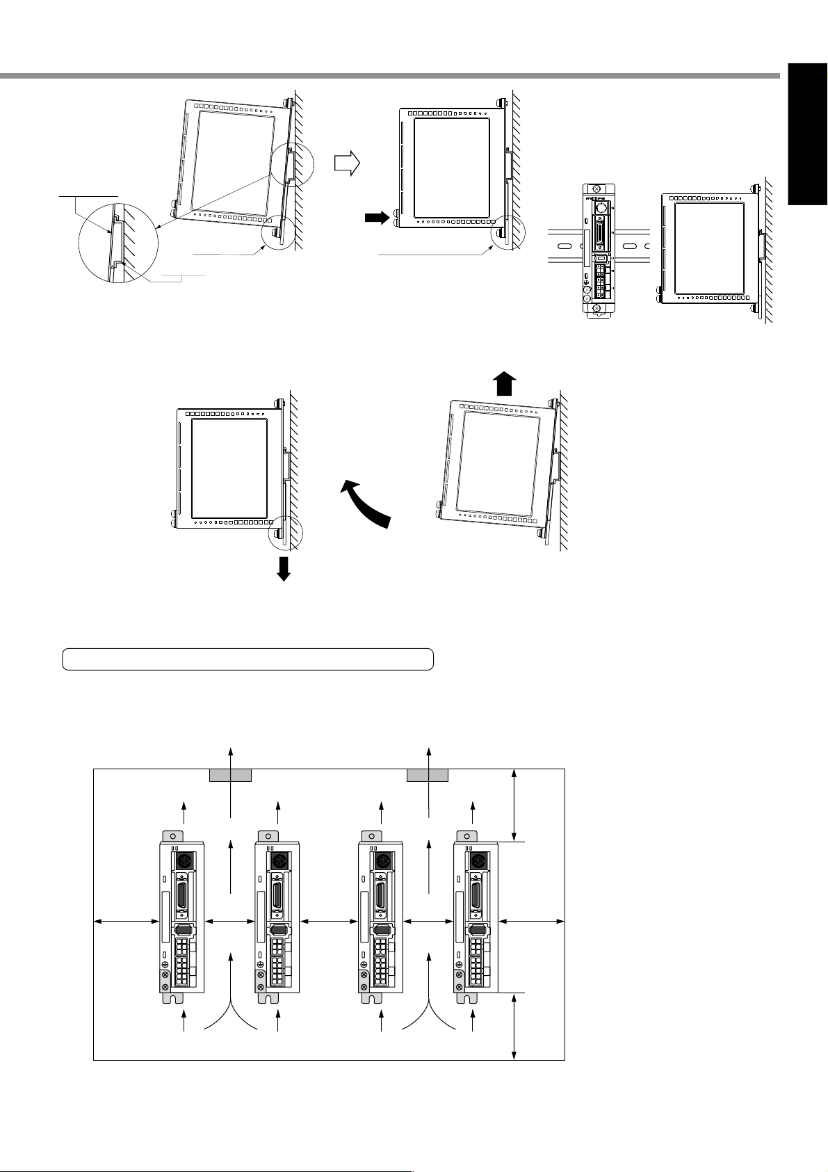
Before Use
Part where DIN
rail is mounted
DIN rail
With rail stop
pushed in
Press lightly.
Ensure that the rail stop
has been pushed in.
[Before Use]
Driver mounted to DIN rail
Hook the upper side of DIN rail
mounting part on the DIN rail.
Press lightly the lower part of
the main body of driver.
(4) Removing from DIN Rail
By lifting the driver, you can remove it
from the DIN rail.
Pull out the lower part
of the driver to the
near side.
With the rail stop released, pull out the
lower part of the driver to the near side.
Mounting Direction and Space Requirements
• Allow enough space to ensure enough cooling.
• Install fans to provide a uniform distribution of temperature in the control box.
• Observe the environmental requirements for the control box, mentioned in the previous page.
min.
40 mm
Fan
Driver Exhaust
Direction
STATUS
ALM CODE
x
6
x
5
x
4
x
3
x
1
Driver Intake
Direction
min.
10 mm
Driver Exhaust
Direction
STATUS
ALM CODE
x
6
x
5
x
4
x
3
x
1
Driver Intake
Direction
min.
10 mm
Fan
Driver Exhaust
Direction
STATUS
ALM CODE
x
6
x
5
x
4
x
3
x
1
Driver Intake
Direction
min.
10 mm
Driver Exhaust
Direction
STATUS
ALM CODE
Driver Intake
Direction
min.
100 mm
x
6
x
5
x
4
min.
40 mm
x
3
x
1
min.
100 mm
This driver has a cooling fan in its bottom and a mounting face.
To install the driver, ensure that there is enough space around the inlet and outlet ports so as not to prevent
intake and exhaust of the fans.
19
Page 20
Installation
Motor
Location
(1) Indoors, where the driver is not subjected to rain water and direct sun beams.
(2) The place where the motor is not exposed to corrosive atmospheres such as hydrogen sulfide, sulfurous acid,
chlorine, ammonia, sulfur, chlorine gas, sulfuric gas, acid, alkali, salt, etc. and is free from splash of flammable
gas, grinding coolant, oil mist, iron powder, chips, etc.
(3) Place in a well-ventilated, and humid- and dust-free space.
(4) The place where the motor can be checked and cleaned easily.
Environmental Conditions
Vibration
Shock
Item
Ambient temperature
Ambient humidity
Storage temperature
Storage humidity
Motor only
With gear (At rotation)
Motor only
With gear
0 to 40°C (free from freezing)
Lower than 85%RH (free from condensation)
-20 to 80°C (free from freezing)
Lower than 85%RH (free from condensation)
49 m/s2 (5G) or less at rotation, 24 5 m/s2 (2.5G) or less
High precision: 24.5 m/s2 (2.5G) max.
98 m/s2 (10G) max.
High precision: 98 m/s2 (10G) max.
Conditions
How to Install
The motor can be installed either vertically or horizontally. Observe the following notes.
(1) When installing in horizontal direction
• Mount the motor with its cable lead-out port faced downward as the countermeasure for oil and water.
(2) When installing in vertical direction
• When installing the motor with speed reducer with its output shaft upside, use the oil-sealed motor to prevent oil
inflow to the motor from the speed reducer. In this case, the oil-sealed motor is a special product.
(3) For the mounting dimensions, refer to a dimensional outline drawing (Pages 194 to 195).
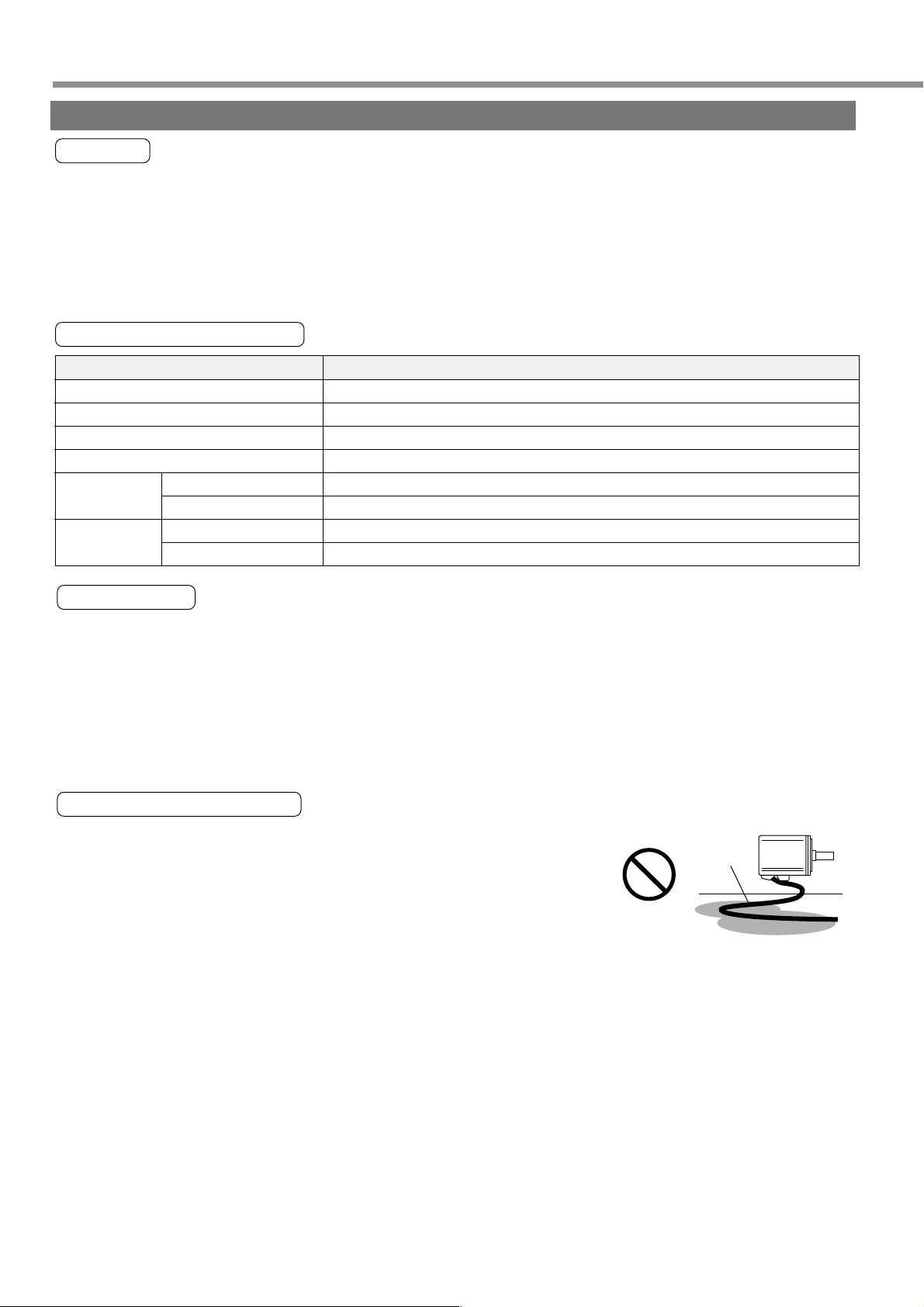
Oil and Water Protections
(1) Don’t use the motor under an environment where oil and water splash over
the motor body.
(2) In combining with the speed reducer, use the oil-sealed motor to prevent oil
inflow to the motor internal through its shaft through-penetration hole. In this
case, the oil-sealed motor used is a special product.
(3) Don’t use the motor with its cable dipped in oil/water.
20
Oil and water
Cable
Motor
Page 21
[Before Use]
Before Use
Cable: Stress relieving
(1) Don’t apply stress to the cable lead-out port and connections by bending and self-weight.
(2) Particularly in the case of application in which the servo motor must be movable, fix the accessory cable of the
motor and house the extension junction cable, which is connected to the terminal end of the said cable, in the
cable bearer to thereby minimize stress acting on the cable by bending.
(3) Make the cable bending radius as large as possible. (Minimum bending radius: to be 20 mm and over.)
Permissible Shaft Load
(1) Do mechanical design so both of radial load and thrust load being applied to the motor shaft during installation
and running are maintained within the permissible value specified for each model.
(2) In using the rigid coupling, take good care of mounting. (Over-bending load on it, if any, would cause damage/
wear of the shaft and shorter life of the bearings.)
(3) Use the flexible coupling of possibly high stiffness to control radial load arising from minor center deviation at the
permissible value or less.
(4) For information on allowable load of an output shaft of each type, refer to Allowable Load of Output Shafts on
Page 196 of Reference.
Installation Notes
(1) When connecting /disconnecting the coupling to/from the motor shaft end, don’t apply
direct impact to the shaft by hammering, etc. (Failure to observe this instruction would
cause damage of the encoder mounted on the counter-load side shaft end.)
(2) Do perfect centering. (Imperfect centering would result in vibration, which would cause
damage of the bearings.)
Motor
21
Page 22
Installation
Console
Location
(1) Indoors, where the driver is not subjected to rain water and direct sun beams. The console is not water-
resistant.
(2) The place where the driver is not exposed to corrosive atmospheres such as hydrogen sulfide, sulfurous acid,
chlorine, ammonia, sulfur, chlorine gas, sulfuric gas, acid, alkali, salt, etc. and is free from splash of flammable
gas, grinding coolant, oil mist, iron powder, chips, etc.
(3) Place in a well-ventilated, and humid-and dust-free space.
(4) Place in a space to be easily accessed for inspection and cleaning.
Environmental Conditions
Item
Ambient temperature
Ambient humidity
Storage temperature
Storage humidity
Vibration
Shock
Altitude
0 to 55°C (free from freezing)
Lower than 90%RH (free from condensation)
-20 to 70°C (free from freezing)
Lower than 90%RH (free from condensation)
Lower than 5.9 m/s2 (0.6G) at 10 to 60 Hz
Compliant with free-fall test JIS C 0044 (1-m fall with a fall guide, twice in each direction)
Conditions
Lower than 1000 m
<Note>
• Avoid strong physical shock to the product.
• Do not drop the product.
• Do not pull the cable with an excessive force.
• Do not set the product near a heat generating device such as heater and large wire wound resistor.
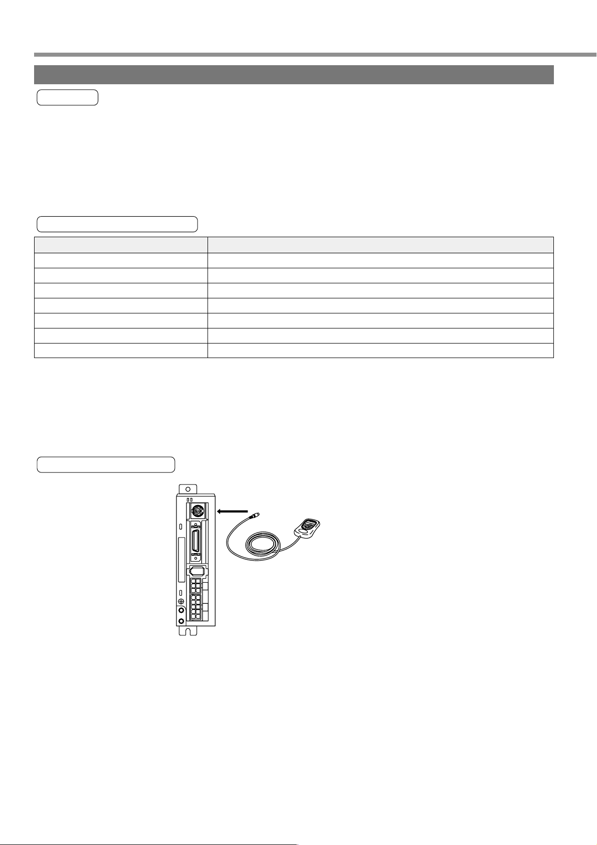
Method of Connection
STATUS
Connect to CN X6.
ALM CODE
x
6
x
5
M
M
O
D
E
S
H
I
F
T
S
S
E
T
x
4
x
3
x
1
<Remarks>
• Securely connect the console connector to the connector CN X6 of the driver.
• Never connect or disconnect the connector by grabbing the connector cable.
22
Page 23

Preparations
Preparations
Page
System Configuration and Wiring ............................... 24
General Wiring Diagram ......................................................................... 24
List of Driver and Compatible Peripheral Equipment ..............................26
Wiring of Connectors CN X1 and X3 (Wiring of Main Circuits) ...............27
Wiring of Connector CN X4 (Connection with Encoder) ......................... 29
Wiring of Connector CN X5 (Connection with Host Controller)............... 30
Wiring of Connector CN X6 (Connection with Personal Computer/Console) ......
Timing Chart .................................................................. 32
Holding Brake ................................................................ 35
Dynamic Brake (DB)...................................................... 36
Homing Operation (Precautions) ................................. 38
Setting the Parameters ................................................. 39
Overview of Parameters .........................................................................39
How to Set ..............................................................................................39
Overview of Console ............................................................................... 39
Overview of PANATERM® ....................................................................... 39
How to Connect ......................................................................................40
Parameter Groups and Listing ................................................................41
31
Using the Console......................................................... 47
Using the Console ................................................................................... 47
The initial State of the Display (7-segment LED) ....................................47
Structure of Each Mode ..........................................................................48
Monitoring Mode .....................................................................................51
Parameter Setting Mode .........................................................................57
Normal Auto Gain Tuning Mode .............................................................. 58
Alarm Clear .............................................................................................59
Test Run (JOG) .......................................................................................60
Test Run Procedures .............................................................................. 61
Copy Function ......................................................................................... 62
23
Page 24
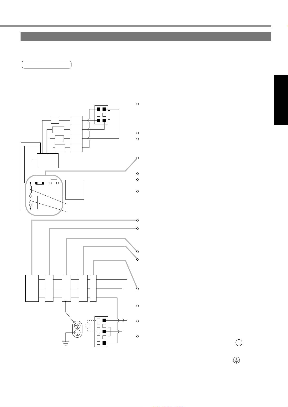
System Configuration and Wiring
p
L1
L2
L3
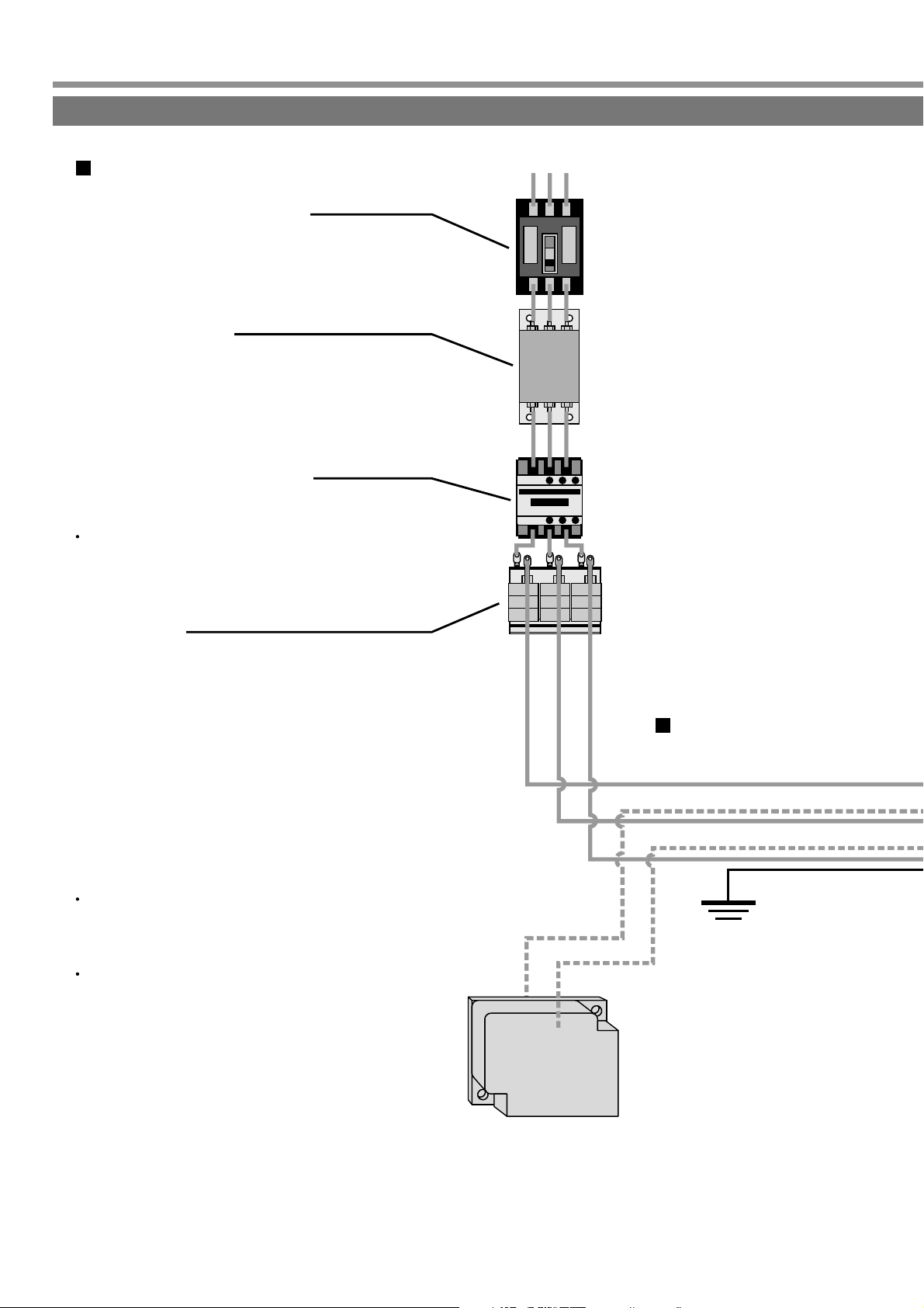
General Wiring Diagram
Main Circuits
Circuit Breaker (NFB)
(Refer to Page 26)
Used to protect the power lines:
overcurrent will shut off the circuit.
(Refer to Page 26, 182)
Noise Filter (NF)
Prevents the external noise from the power line,
and reduces the effect of the noises generated
by the servo motor.
(Refer to Page 26)
Magnetic Contactor (MC)
Turns on/off the main power of the servo motor.
Used together with a surge absorber.
Never start or stop the motor with the
magnetic contactor.
(Refer to Page 191)
Reactor (L)
Reduces the harmonic current in the main
power.
5 Pins - 3 Pins of CN X1 ---
When using the driver for an application of large
regenerative energy, connect an external
regenerative resistor between P (5 pins) and B
(3 pins) of connector CN X1.
Install an external regenerative resistor on
incombustible material, such as metal, and
provide the regenerative resistor with a
protective device such as temperature fuse, etc,
to prevent the resistor from being overheated.
Regenerative discharge resistor
(Optional)
Wiring connection to
Connector CN X1
(Connection with the input power su
P
B
Ground
24
Page 25
[Preparations]
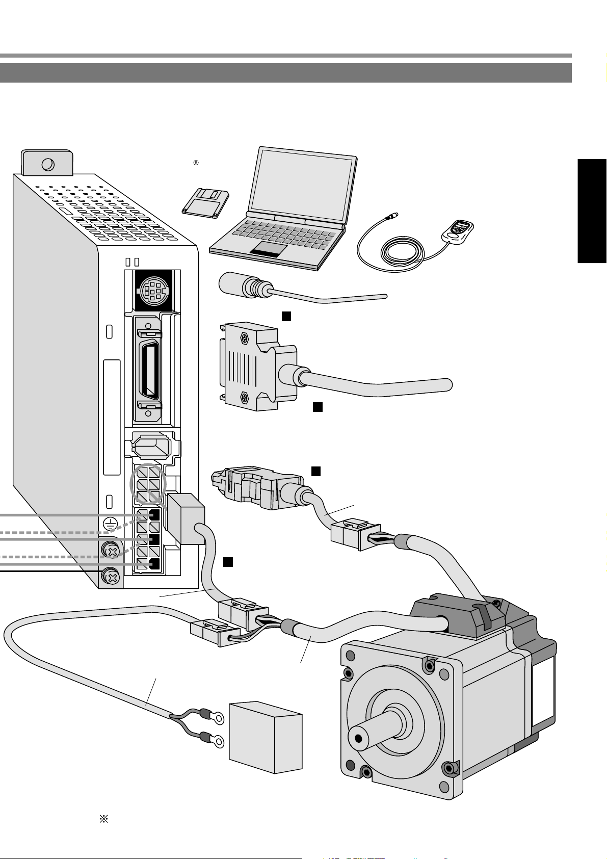
Preparations
L1
L2
Setup support software
"PANATERM "
STATUS
ALM CODE
x6
x5
Personal computer
Console
M
M
O
D
E
S
H
I
F
T
S
S
E
T
Wiring to Connector CN X6
(Connection with personal computers and consoles)
Wiring to Connector CN X5
(Connection with host controllers such as PLC, etc.)
ply)
MKDET1310P 200V
L1
L1
L2
L2
L3L3L3
Junction cable for motor
Junction cable for brake
x4
x3
x1
Wiring to Connector CN X4
(Connection with encoder)
Junction cable for encoder
Wiring to Connector CN X3
(Connection with each phase of motor
windings)
Motor cable
Power supply for motor brake
(24 V DC)
For connections, refer to Points in Wiring (Page 27).
25
Page 26
System Configuration and Wiring
List of Driver and Compatible Peripheral Equipment
Series
MKDE
MLDE
MKDE
MLDE
MKDE
MLDE
Driver
Power
voltage
1-phase,
100V
1-phase,
200V
3-phase,
200V
Output
50W
100W
200W
50W
100W
200W
400W
50W
100W
200W
400W
Required
Power
(rated load)
0.3kVA
0.4kVA
0.5kVA
0.3kVA
0.5kVA
0.9kVA
0.3kVA
0.5kVA
0.9kVA
Circuit breaker
(rated current)
BBC25N
(5A)
BBC2101N(10A)
BBC25N
(5A)
BBC2101N(10A)
BBC35N
(5A)
BBC3101N(10A)
Noise filter
DV0P4160
Magnetic contactor
(composition of
contacts)
BMFT61041N
(3P+1a)
BMFT61542N
(3P+1a)
BMFT61042N
(3P+1a)
0.75mm
AWG18
Circuit breaker, magnetic contactor: manufactured by Matsushita Electric Industrial Co., Ltd.
For compliance with EC Directives, don’t fail to connect the circuit breaker (with LISTED, Mark), which is
authorized and certified under IEC and UL Standards, between the power supply and the noise filter.
Noise filter
For DV0P4160, refer to Page 182.
Cable
diameter
(L1, L2, L3,
U, V, W, E)
2
-
0.85mm
2
< Remarks >
• For wiring to the power connector, motor connector and earth terminal, use the copper conductors of 60°C and
over in the temperature rating.
• For the connector-side earth cable, use the cable of 0.75 mm2 - 0.85 mm2 (AWG18) in diameter.
• For the mounting screw-side earth cable, use the cable of 2.0 mm2 (AWG14) or more in diameter.
• Where two or more drivers are used and the noise filters for the drivers are mounted in set in the power unit, feel
free to consult with the noise filter manufacturer.
26
Page 27
[Preparations]
Preparations
Wiring of Connectors CNX1, X3 (Wiring of Main Circuits)
• Don’t fail to request an electric wiring specialist for wiring.
• Don’t switch ON the electric power until completion of the wiring, to prevent electric shock.
Points in Wiring
(1) For the cable diameter used, refer to “List of Driver and Compatible Peripheral Equipment” (page 26).
(2) Insert securely the connectors.
CN X3
(Driver side)
Do wiring in perfect color matching between the
identification colors of the motor lead-out cable and
corresponding motor output terminal (U, V, W).
Connect U (1 pin), V (4 pins), W (6 pins) and E (3 pins)
respectively.
Avoid shorting and ground fault.
At this stage, don't connect the power supply cable.
Adopt a duplex circuit as the brake control circuit so it can
actuate even with emergency stop signal from external
device.
The magnetic brake has no polarity.
For the power capacity and operation detail of the magnetic
brake, refer to the "Holding Brake" (page 35).
Install the surge absorber (C-5A2 or Z15D151 made by
Ishizuka Electronic).
Read the driver nameplate to check the power specification.
Provide circuit breaker or leakage breaker without fail. In this
case, use a leakage breaker to which countermeasure for high
frequency is applied for "inverter application".
Motor
Red
White or
yellow
Black
Green/
yellow
36
U
1
V
W
E
DC
2
3
4
24V
14
DC power for brake use
Surge absorber
Fuse (5A)
NFB
NF MC L
Power
(Driver side)
Ground resistance: 100Ω max.
For applicable wire, see page 26.
CN X1
5
P
B
16
10
L1
L2
L3
Don't fail to provide noise filter.
Provide the magnetic contactor coil with surge absorber.
Never start/stop the motor by magnetic contactor.
Install AC reactor.
For three-phase 200V, connect L1 (10 pints), L2 (8 pins) and
L3 (6 pins).
For single-phase 100V and 200V, connect L1 (10 pins) and
L3 (6 pins).
Connect to the grounding system of the facility.
Connect the driver protective earth terminal ( ) and the
protective earth (earth plate) of the control panel for
preventing of electric shock. In this case, don't co-clamp the
earth wires to the protective earth terminal ( ). Two
protective earth terminals are provided.
27
Page 28
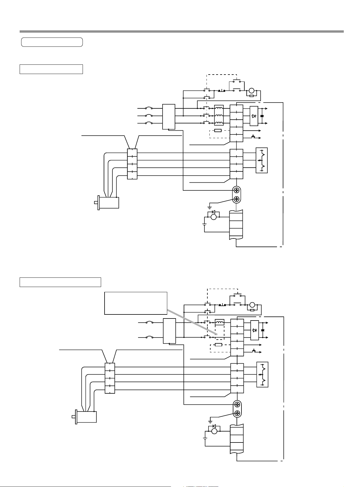
System Configuration and Wiring
Wiring Diagrams
Compose such a power supply as to switch OFF the power against alarm output.
For three-phase 200V
Power supply
172167-1
(Tyco Electronics
AMP K.K.)
Motor
Red
White or
yellow
Black
Green
yellow
NFB
172159-1
(Tyco Electronics
AMP K.K.)
1
2
3
4
Noise
filter
ON
MC
MC
OFF
L
5557-10R-210
(Molex Incorporated)
5557-06R-210
(Molex Incorporated)
V
ALM
DC
12~24V
10
13
8
6
5
3
1
4
6
3
9
ALM
L1
L2
L3
P
B
U
V
W
E
ALM
COM —
MC
P
N
P
N
CN X1
CN X3
CN X5
For Single-phase 100V/200V
172167-1
(Tyco Electronics
AMP K.K.)
Motor
Red
White or
yellow
Black
Green
yellow
For single-phase 200V,
use the reactor for
three-phase.
NFB
Power supply
172159-1
(Tyco Electronics
AMP K.K.)
1
2
3
4
Noise
filter
ON
MC
MC
OFF
L
5557-10R-210
(Molex Incorporated)
5557-06R-210
(Molex Incorporated)
V
ALM
DC
12~24V
10
6
5
3
1
4
6
3
9
13
ALM
L1
L2
L3
P
B
U
V
W
E
ALM
COM —
MC
P
N
P
N
CN X1
CN X3
28
CN X5
Page 29
Preparations
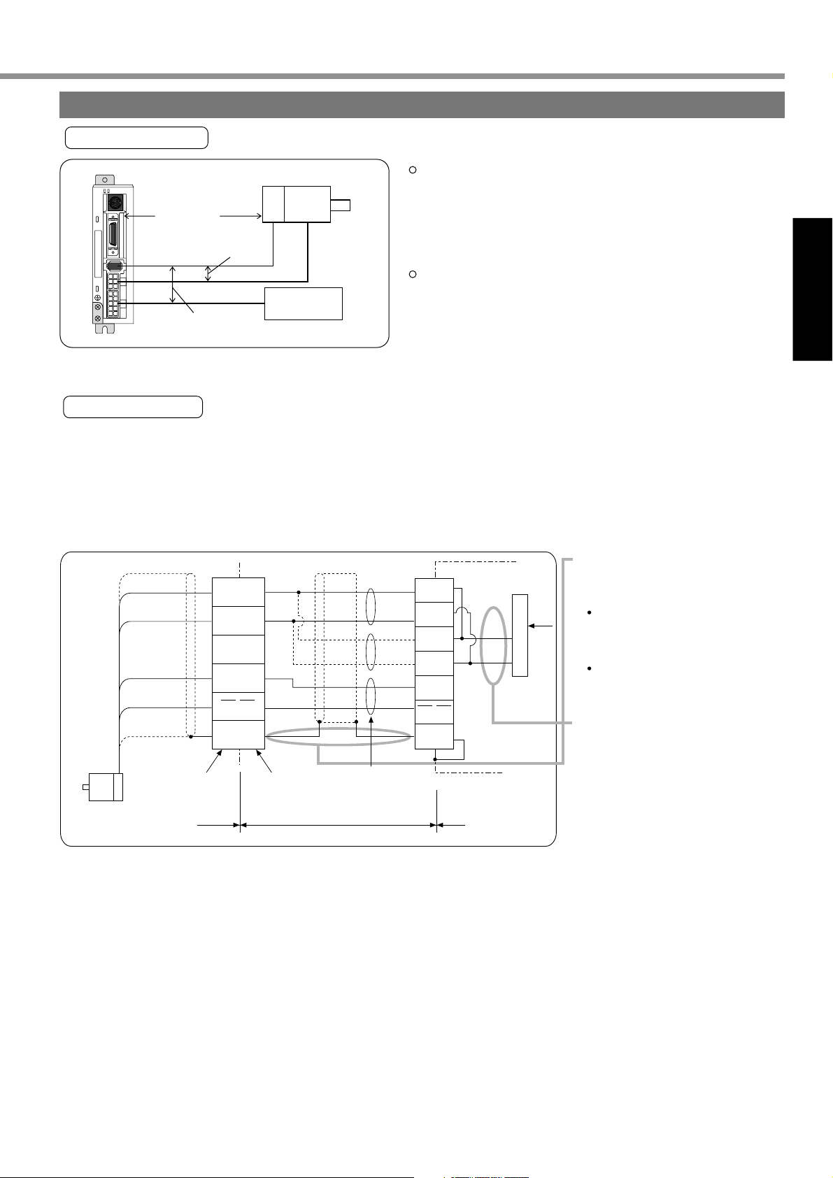
Wiring to Connector CN X4 (Connection with Encoder)
Points in Wiring
[Preparations]
STATUS
ALM CODE
x
6
20 m max.
x
Encoder
5
x
4
x
3
x
1
30 cm min.
30 cm min.
Power
section
Motor
Cable length between the driver and the motor - 20 m max.
If this cable length exceeds 20 m, consult with the
dealer/distributor from which you have purchased the
driver.
Keep 30 cm or more spacing from the main circuit wiring.
Neither guide this wiring through the same duct, together
with the main circuit nor bundle these two together.
Wiring Diagram
¥ When you plan to make an encoder junction cable by yourself, refer to Requests on a self-made encoder junction
cable (For connectors, refer to Optional Parts (Connector Kits for Connection of Motor and Encoder) on Page
186 of Reference edition).
(1) Refer to the wiring diagram below.
(2) Cable used: Shielded twist pair cable of 0.18 mm
bending resistance.
5
0V
4
+5V
1
2
3
6
FG
172160-1172168-1
(made by Tyco Electronics AMP K.K.)
Junction cable
Servo motor
Black
White
(NC)
Light blue
Purple
Shielded
cable
(made by Tyco
Electronics AMP K.K.)
Motor side Servo driver side
TX/RX
TX/RX
2
(AWG 24) minimum in conductor diameter that is excellent in
(3) For signal/power wiring in pair,
Case
2
1
4
3
5
6
0V
+5V
0V
+5V
TX/RX
TX/RX
FG
X4CN
0V
Regulator
+5V
use twist pair cable.
(4) Shielding treatment
Driver-side shield sheath:
Connect to CNX4 connector
case (FG).
Motor-side shield sheath:
Connect to 6 pins.
(5) Where the cable length
exceeds 10 m, do double-
wiring for the encoder power
Twist pair
(+5V, 0V), as illustrated left.
(6) Connect nothing to the empty
terminal (NC) of the
connector.
(7) Don’t use a cable pair composed of the motor cable and encoder cable which were shielded in batch.
29
Page 30
System Configuration and Wiring
Wiring of Connector CN X5 (Connection with Host Controller)
Points in Wiring
V
Power
Supply
Motor
DC
Unit
Controller
Within 3 m
30 cm or More
COM+
COM-
FG
CN X5
STATUS
GND
Place any peripheral equipment such as a host controller within 3 meters
ALM CODE
x
6
x
5
x
4
x
3
x
1
from the driver.
Separate the wiring at least 30 cm or more from the main circuit wires.
The wiring should neither run through a same duct as the main circuit
wires nor be bundled together with them.
A customer is requested to prepare for power supply for control signals
(V
DC
1
2
) between COM+ and —COM.
Voltage: DC +12 to 24V
For such wiring as command pulse input or encoder signal output, etc.,
use shielded twist pair cable.
Neither apply 24V or more to a control signal output terminal, nor run
50mA or higher.
If you directly activate a relay using the control signal output, install a
diode in parallel with a relay in the direction shown in the left figure.
Without a diode or with it but placed in the opposite direction, the driver
will be damaged.
The Frame Ground (FG) is connected to an earth terminal in the driver.
For detailed information on wiring of respective pins, refer to Page 65 (position control mode) and Page
103 (internal velocity control mode) of connections for each control mode.
CN X5 Connector Specifications
Connectors on Driver Side
10226-52A2JL
Connector (solder type)
Connector cover
Compatible Connectors on User Side
Part Name
10126-3000VE
10326-52A0-008
Part No.
Manufacturer
Sumitomo 3M Ltd.
<Remarks>
• For details, refer to “Optional Parts” on Page 188 of Reference edition.
30
Page 31

[Preparations]
Preparations
x
5
x
6
STATUS
ALM CODE
x
5
x
6
STATUS
ALM CODE
Wiring of Connector CN X6 (Connection with Personal Computer/Console)
• It is capable of RS232C communications.
For RS232C communications only
1) Connect the personal computer and driver 1:1 through RS-232C, and use “PANATERM®” (optional component),
the setup supporting software. Running “PANATERM®” on your personal computer, you can have convenient
functions with excellent operability, such as various types of monitors, parameter settings/changes, waveform
graphic displays, etc.
2) You can connect a host (personal computer, or host controller) and driver through RS 232C for communications.
For detailed information, refer to “Communications” on Page 158 of Reference edition.
Connection
Refer to "Optional
Parts" of dedicated
connecting cables.
Insert or pull out a connector
only after cutting power off
both personal computer and driver.
Tighten stop screws firmly.
Connection with Console
CN X6
Connect to CN X6.
Back Plane of Connector for RS232C
M
M
O
D
E
S
H
I
F
T
S
S
E
T
31
Page 32

Timing Chart
Power Supply
Internal Control
Power Supply
Initialization of
Driver
Servo-ON Input
(SRV-ON)
(X5 2 pins)
Dynamic Brake
Motor Energized
Brake Release
Output
(BRK-OFF)
(X5 11 pins)
Position/Velocity
Command
ON
ON
Normal Operation
OFF
* 1
OFF (Braking Operation)
ON
(Brake Release)
OFF
ON
Not Energized
Energized
Not input
Input
100ms or Longer
Approx.
700 ms
Established
Initialize Approx. 2 seconds
Approx. 40 ms
Approx. 1 - 5 ms
Approx. 10 ms
Approx. 2 seconds
OFF
-After Power-ON (Receiving Servo-ON Signal)
<Cautions>
• The above chart shows timing from AC power-ON to command input.
• Enter Servo-ON signal and external command according to the above timing chart.
*1: During this period, the SRV-ON signal has not been accepted although it was mechanically input.
32
Page 33

Preparations
After an Alarm event (during Servo-ON)
[Preparations]
Alarm
Dynamic Brake
Motor Energized
Servo Alarm
(ALM)
Brake Release
(BRK-OFF)
Normal
Energized
Not Alarm
Release (ON)
A
1 - 5 ms
Setting of Pr6B
Operation (OFF)
t1 *1
Error
Operation *2
Not Energized
Alarm
Approx. 30r/min
Setting of Pr6B
Release (ON)
B
t1 *1
Operation (OFF)
Approx. 30r/min
<Cautions>
*1. A value of t1 is a value of Pr6B or time needed for decreasing the motor speed to approx. 30 r/min,
whichever is shorter.
*2. For operation of the dynamic brake following an alarm event, also refer to the description in “Sequence at
Alarm” (“Parameter Setting” for every control mode) on Pr68.
After an Alarm is Cleared (during Servo-ON Command)
120ms or Longer
Alarm Clear
Input (A-CLR)
Dynamic Brake
Motor Energized
Brake Release
Output
Servo Alarm
Output (ALM)
Position/Velocity
Command
(BRK-OFF)
Operation
Not Energized
Operation (OFF)
Alarm
Cleared
Approx. 40 ms
100ms or Longer
Release
Energized
Release (ON)
Approx. 10 ms
Not Alarm
No Input
Input Enabled
33
Page 34

Timing Chart
Servo-ON/OFF Operation When the Motor is Stopped
(During normal operation, perform the Servo-ON/OFF operation after the motor stops.)
Servo-ON Input
(SRV-ON)
Dynamic Brake
Motor Energized
Brake Release
Output (BRK-OFF)
When you turn off the power of the electromagnetic brake, the motor brake will run. When you turn on the
power of the electromagnetic brake, the motor brake will be released.
OFF
Approx. 1 - 5 ms
Operation *3
Not Energized
Approx. 40 ms
Operation (OFF)
ON
Release
Energized
Approx. 10 ms
Release (ON)
OFF
Approx. 1 - 5 ms
Operation *2
t1 *1
Not Energized
Operation (OFF)
<Cautions>
*1. A value of t1 depends on a setting of Pr6A.
*2. For the operation of the dynamic brake during Servo-OFF, also refer to the description of “Sequence
during Servo-OFF” (“Parameter Settings” of every control mode) on Pr69.
*3. Servo-ON input will not be active until the motor rotation speed falls below approx. 30r/min.
Servo-ON/OFF Operation When the Motor is Rotating
(The following chart shows timing in the case of emergency stop or trip. You cannot use Servo-ON/OFF
repeatedly.)
Servo-ON Input
(SRV-ON)
Dynamic Brake
OFF
ON
* 4
Operation Release
OFF
Approx. 1 - 5 ms
Operation *3
Motor Energized
Not Energized
Brake Release
Output
(BRK-OFF)
Operation
(OFF)
Number of Motor Rotations
Motor Rotation
Speed
Servo-ON input will not be active
until the motor rotation speed
falls below approx. 30r/min.
Approx.
Approx. 30 r/min
Servo enabled
40 ms
Energized
Approx. 10 ms
Release
(ON)
Motor Rotation Speed A
Approx. 30 r/min
Setting of Pr.6B
Release
(ON)
Motor Rotation Speed B
Approx. 30 r/min
Not Energized
Setting of Pr.6B
Operation
t1 * 1
Operation
t1 * 1
(OFF)
When the motor rotation speed
falls below 30r/min earlier.
(OFF)
When the time defined by
Pr.6B is reached earlier.
<Cautions>
*1. A value of t1 is a value of Pr6B or time needed for decreasing motor speed to approx. 30 r/min,
whichever is shorter.
*2. Even if SRV-ON signal turns on again during deceleration of the motor, SRV-ON input does not become
active until it stops.
*3. For operation of the dynamic brake during Servo-OFF, also refer to the description of “Sequence at
Servo-OFF” (“Parameter Settings” of every control mode) on Pr69.
*4. Servo-ON input will not be active until the motor rotation speed falls below approx. 30r/min.
34
Page 35

Preparations
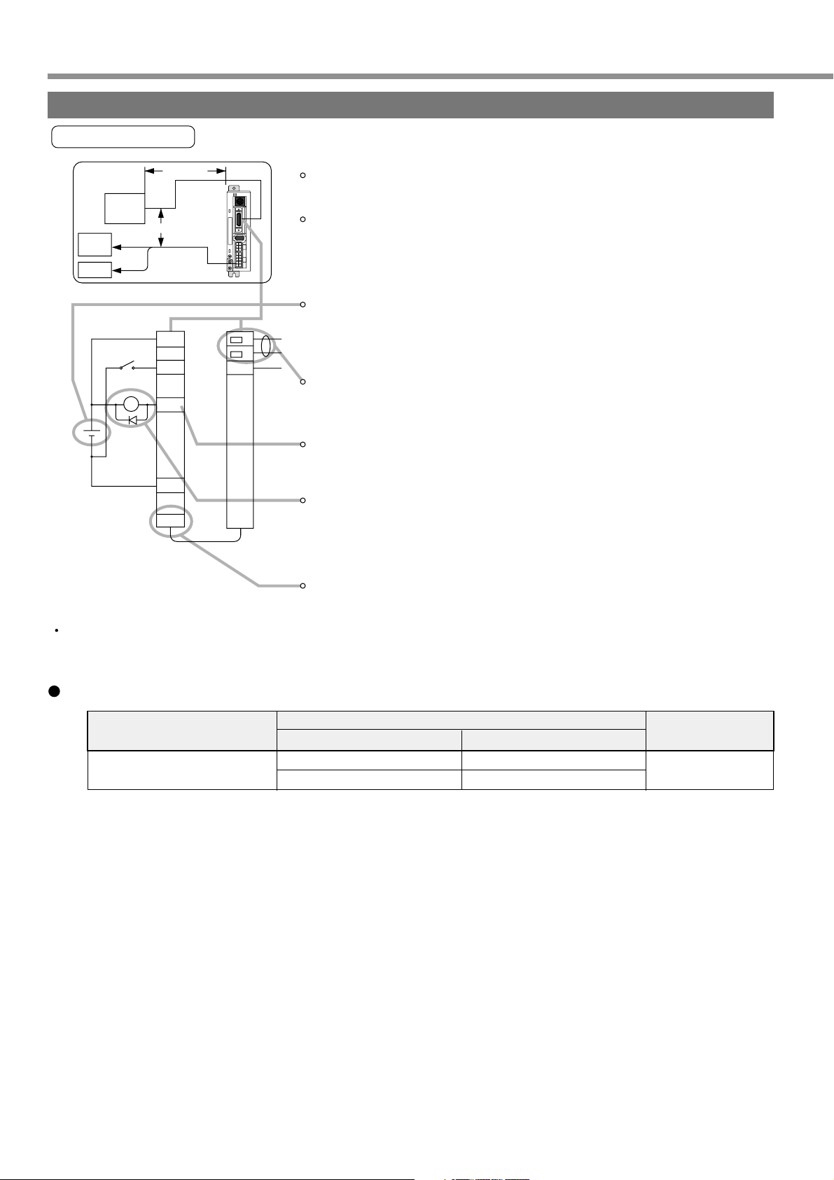
Holding Brake
[Preparations]
The brake is to hold a work (movable part) and prevent it from dropping by gravity when power to the servo is shut
off for the purpose of driving a vertical shaft in the servo motor.
<Caution>
The brake built in the servo motor is only for holding, namely, maintaining,
stopped condition. Thus, you must not use it for “braking” to stop moving load.
Wiring (Example)
This circut shows an example
in which a brake release (BRK-OFF)
signal from the driver is used to
control the brake.
<Remarks and Cautions>
1. A brake coil has no polarity.
2. A customer is requested to provide for power supply for the brake. In addition, do not use power supply for
control signals (VDC) for driving the brake.
3. In order to suppress surge voltage due to ON/OFF operation of the relay (RY), install a surge absorber. When
you’re using a diode in place of a surge absorber, note that start of the servo motor is delayed in comparison with
when the latter is used.
4. For a surge absorber for the brake, refer to “Recommended Parts” on Page 192 of Reference edition.
5. The recommended parts are those specified for measuring brake release time. In some cases, reactance of
electric wires may vary depending on wire length, causing sporadic rise of voltage. Select a surge absorber so
that the relay coil voltage (maximum rating: 30V, 50 mA) and voltage between brake terminals do not exceed a
rated value.
Driver
BRK-OFF
11
COM-
13
CN X5
RY
12~24V
DC
V
Cut off upon emergency stop
Surge absober
RY
Power for brake
DC24V
Motor
Brake coil
Fuse
(5A)
• For timing of brake release upon power-on or that of brake operations in case of servo-off/alarm while the motor
• In case of Servo-OFF or alarm while the motor is rotating, you can set with the parameter (i.e., Pr6B: Mech.
<Remarks>
1. The servo motor with built-in brake could result in brake lining sound (Chattering, etc.) while it is running. But this
2. When the current is fed into the brake coil (with the brake kept released), it could result in leak magnetic flux from
• Excitation voltage should be DC24V ± 10%.
• The values in the above table are representative characteristics (except static friction torque, releasing voltage,
• A backlash of the brake is ± 1˚ of a setup value.
• Allowable angular acceleration of MUMA series: …..10000 rad/s
• Service life of the number of accelerations/decelerations with the allowable angular acceleration is 10 million
BRK-OFF Signal Output Timing
is rotating, refer to “Timing Chart” on Page 32.
break action set-up at motor in motion) time till BRK-OFF signal turns off (i.e., the brake is actuated) after the
motor is freed from energized state. For details, refer to “Parameter Settings” of every control mode.
is not a problem.
the shaft, etc. Be careful when a magnetic sensor, etc. are used around the motor.
Specifications of Holding Brake
Motor
Series
MUMA
Motor Output
50W, 100W
200W, 400W
Static Friction
Torque (N/m)
0.29 or higher
1.27 or higher
Inertia
-4
x 10
kg•m
0.003
0.03
Intake Time
2
25 or shorter
50 or shorter
(ms)
Release Time
(ms)
20 or
shorter(30)
15 or shorter
(100)
*1 A value when the surge absorber is used.
Values given in ( ) are actual values measured with diodes (V03C manufactured by HITACHI Semiconductor
and Devices Sales Co., Ltd.).
and excitation current).
2
times or greater. (The number of accelerations/decelerations till backlash of the brake changes drastically.)
Excitation
Current DC A
*1
(during cooling)
0.26
0.36
Release
Voltage
DC1V or
higher
Allowable
Workload per
Braking J
39.2
137
Allowable
Workload
Total
x 103J
4.9
44.1
35
Page 36

Dynamic Brake
Dynamic Brake
Dynamic brake is built in this driver for emergency stop.
For this dynamic brake observe the precautions given below.
<Notes>
1. This dynamic brake functions for emergency stop of the driver.
Don’t start and stop by ON/OFF of the Servo-ON signal (SRV-ON signal).
Doing so could result in rupture of the dynamic brake circuit built in the driver.
If the motor is started by an external unit, it would acts as a generator and, as a
result, short current would flow while the dynamic brake is acting, which could
then result in fuming and fire.
2. The dynamic brake is a short-time rating brake just for emergency stop use. If the dynamic brake acts
commencing from the time of high speed running, provide a lead time of about 3 minutes after complete stop.
This dynamic brake can be started in the following cases.
(1) Against “Servo OFF”
(2) When any of the protective functions actuate
(3) When the overtravel inhibit inputs (CWL, CCWL) of the connector CN X5 actuate
In the above cases (1) - (3), it is selectable by setting up the applicable parameters whether the dynamic
brake is started or put in free running during deceleration or after complete stop.
However, the dynamic brake is kept actuating when the power is switched OFF.
36
Page 37

[Preparations]
Preparations
(1) Setting driving conditions through deceleration and stop by turning on Servo-OFF (Pr69)
Sequence at
Servo-OFF (Pr69)
Setting of Pr69
0
1
2
3
4
5
6
7
Driving Conditions
During
deceleration
D B
Free Run
D B
Free Run
D B
Free Run
D B
Free Run
After stop
D B
D B
Free Run
Free Run
D B
D B
Free Run
Free Run
Status of
Deviation Counter
Cleared
Cleared
Cleared
Cleared
Holding
Holding
Holding
Holding
(2) Setting of Driving Conditions from Deceleration till Stop by Turning on Protective Function (Pr68)
Sequence at
alarm (Pr68)
Setting of Pr68
0
Driving Conditions
(During
deceleration)
D B
(After stop)
D B
Status of
Deviation Counter
Cleared
1
2
3
Free Run
D B
Free Run
D B
Free Run
Free Run
Cleared
Cleared
Cleared
(3) Setting of Driving Conditions through Deceleration and Stop by Enabling Overtravel Inhibit Input
(CWL, CCWL) (Pr66)
Deceleration and stop
set-up at overtravel
inhibit (Pr66)
Setting of Pr66
0
1
2
(Position control.)
2
(Internal velocity
control.)
Driving Conditions
During
deceleration
D B
After stop
Free Run
Free Run Free Run
Servo Lock Servo Lock
Speed
zero clamp
Speed
zero clamp
37
Page 38

Homing Operation (Precautions)
In initialization (i.e., operation to return to a home position) by using the host controller, if origin input (Z-phase
from the encoder) is entered before the motor has not adequately decelerated since the proximity sensor was
activated, the motor may not stop at a requested position. In order to prevent this, determine positions where the
proximity input and origin input turn on, by taking into consideration the number of pulses required for successful
deceleration. As settings of parameters “acceleration/deceleration time” have also effects on initialization,
consider both positioning and initialization when you set them.
For detailed information on initialization, refer to the operating manual for the host controller.
Example of Homing Operation
Proximity dog on .... When the proximity input turns ON, the motor will start to decelerate, and stop when a first
origin input (Z phase) is entered.
Proximity Input
Speed
Origin Input
Proximity Sensor Dog
Z-phase output from encoder
Proximity dog off .... When the proximity input turns ON, the motor will start to decelerate, and stop when a first
origin input (Z phase) is entered after the proximity input turns off.
Proximity Sensor Dog
Proximity Input
Speed
Origin Input
Z-phase output from encoder
38
Page 39

Preparations
Setting the Parameters
[Preparations]
Overview of Parameters
The servo driver has various parameters to set up its characteristics, functions, etc. This Section describes the
function and purpose of each parameter. Before using, understand well the descriptive contents and adjust each
parameter to the condition optimum to your intended operational conditions.
How to Set
Parameters can be set up on;
(1) Console
(2) the screen of personal computer (PC) wherein the setting-up support software “PANATERM®” for E-Series was
installed.
<Remarks>
For how to set up the parameters on the PC screen, refer to “PANATERM®” Instruction Manual.
Overview of Console
Console is able to:
(1) Monitor rotation speed, torque, positional deviation, input/output power, pulse input, load factor, etc. of servo-
motors,
(2) Setup and save parameters of servo-motor drivers,
(3) Write the data into memory (EEPROM),
(4) Execute normal-auto-gain tuning,
(5) Indicate current alarms and make reference to error history,
(6) Operate test runs,
(7) Make copies of parameters and clear alarms.
Overview of PANATERM®
This PANATERM® is able to;
(1) Set up, save and write the driver parameters in the memory (EEPROM),
(2) Monitor I/O data, pulse input data and load factor,
(3) Refer to current alarm display and error history,
(4) Measure the waveform graphic data and to call the saved data,
(5) Execute auto gain tuning,
(6) Measure the frequency characteristic of the mechanical system.
39
Page 40

Setting the Parameters
How to Connect
RS-232C connecting cable
• DV0P1960 (for DOS/V)
STATUS
ALM CODE
x
6
Connecting to CNX6
x
5
Console
x
4
x
3
x
1
• DV0P3690
M
M
O
D
E
S
H
I
F
T
S
S
E
T
Setup Disk for Setting-up Support
Software “PANATERM®”
• DV0P4230: Japanese version
• DV0P4240: English version
For the latest version, contact us.
Connecting to CNX6
<Notes>
• Securely connect the connector with the connector CN X6 of the driver.
• Never insert or pull out the connector while holding a cable.
40
Page 41

Preparations
Parameter Groups and Listing
[Preparations]
Group
Function selecting
Adjustment
Position control
Internal velocity and
torque control
Sequence
Parameter No.
(Pr )
00 - 0E
10 - 1E
20 - 2F
30 - 35
40 - 4E
53 - 59
5E
60 - 6B
70 - 73
Briefing
These parameters are used to select control mode, allocate I/O
signals and to set up communication baud rate.
These parameters are used to set up servo gains (1st, 2nd) of
position, velocity, integration, etc. and the time constants of various
filters.
These parameters related to real time auto tuning and damping function
are used to set up the modes and to select mechanical stiffness.
These parameters are used to set up the data related to
interchange of 1st gain 2nd gain.
These parameters are used to set up input form and logical
selection of command pulses and dividing of encoder output pulses,
and to set up the dividing multiplier ratio of command pulses, etc.
These parameters are used to set up internal velocity (1 - 4 velocity,
JOG speed), acceleration/deceleration time, etc.
This parameter is used to set up torque limit.
These parameters are used to set up the conditions for detecting
output signals such as positioning end, zero speed, etc. and the
conditions for corrective action against positional over-deviation.
Furthermore, these are used to set up deceleration and stopping
against power OFF, alarm output and servo OFF, and the conditions
for clearing the deviation counter.
41
Page 42

Setting the Parameters
Parameters for Selecting Function
Parameter No.
(Pr )
*00
*01
*02
03
*04
05
*06
07,08
09
0A,0B
*0C
0D
0E
0F
Axis address
7-segment LED for console, initial condition display
Control mode set up
(For manufacturer use)
Overtravel Input inhibit
(For manufacturer use)
ZEROSPD/TC input selection
(For manufacturer use)
Warning output selection
(For manufacturer use)
Baud rate set-up of RS232C
(For manufacturer use)
(For manufacturer use)
(For manufacturer use)
Parameter description Range Default Unit
1 - 15
0 - 15
0 - 2
—
0 - 1
—
0 - 2
—
0 - 6
—
0 - 2
—
0 - 1
—
Parameters for adjusting the time constants of gain filter
Parameter No.
(Pr )
10
11
12
13
14
15
16
17
18
19
1A
1B
1C
1D
1E
1F
26
27 - 2A
2B
2C
1st position loop gain
1st velocity loop gain
1st velocity loop integration time constant
1st speed detection filter
1st torque filter time constant
Velocity feed forward
Feed forward filter time constant
(For manufacturer use)
2nd position loop gain
2nd velocity loop gain
2nd velocity loop integration time constant
2nd speed detection filter
2nd torque filter time constant
1st notch frequency
1st notch width selection
(For manufacturer use)
Software limit function
(For manufacturer use)
Damping frequency
Damping filter setting
Parameter description Range Default Unit
0 - 32767
1 - 3500
1 - 1000
0 - 5
0 - 2500
–2000 - 2000
0 - 6400
—
0 - 32767
1 - 3500
1 - 1000
0 - 5
0 - 2500
100 - 1500
0 - 4
—
0 - 1000
—
0 - 5000
–200 - 2500
1
1
2
0
1
0
1
0
2
0
2
0
0
0
<63>
<35>
<16>
<0>
<65>
<300>
<50>
0
<73>
<35>
<1000>
<0>
<65>
1500
2
0
10
0
0
0
—
—
—
—
—
—
—
—
—
—
—
—
—
—
1/s
Hz
ms
—
0.01ms
0.1%
0.01ms
—
1/s
Hz
ms
—
0.01ms
Hz
—
—
0.1 rev
—
0.1Hz
0.1Hz
Related control mode
P • P2 • S
P • P2 • S
P • P2 • S
P • P2 • S
P • P2 • S
P • P2 • S
P • P2 • S
Related control mode
P • P2
P • P2 • S
P • P2 • S
P • P2 • S
P • P2 • S
P • P2
P • P2
P • P2
P • P2 • S
P • P2 • S
P • P2 • S
P • P2 • S
P • P2 • S
P • P2 • S
P • P2
P • P2
P • P2
*1
—
—
—
—
—
—
—
—
*1
—
—
*1
Parameters for Auto Gain Tuning
Parameter No.
(Pr )
20
21
22
23,24
25
2D,2E
2F
Inertia ratio
Real time auto tuning set-up
Machine stiffness at auto turning
(For manufacturer use)
Normal auto tuning motion set-up
(For manufacturer use)
Adaptive filter frequency
Parameter description Range Default Unit
0 - 10000
0 - 7
0 - 15
—
0 - 7
—
0 - 64
42
<100>
1
4
0
0
0
<0>
%
—
—
—
—
—
—
Related control mode
P • P2 • S
P • P2 • S
P • P2 • S
P • P2 • S
P2
*1
—
—
*1
Page 43

Preparations
Parameters for Adjustment for 2nd Gain
P: High velocity response positioning control, P2: High function positioning control, S: Internal velocity control
[Preparations]
Parameter No.
(Pr )
30
31
32
33
34
35
36 - 3F
2nd gain action set-up
Position control switching mode
Position control switching delay time
Position control switching level
Position control switching hysteresis
Position loop gain switching time
(For manufacturer use)
Parameter description Range Default Unit
0 - 1
0 - 10
0 - 10000
0 - 20000
0 - 20000
0 - 10000
—
<1>
<10>
<30>
<50>
<33>
<20>
0
—
—
166µs
—
—
Setup value
× 166µs
—
Related control mode
P • P2
P • P2
P • P2
P • P2
P • P2
P • P2
—
• *-marked parameter No. in the above table is validated by writing the parameter No. in EEPROM after set
up and re-switching ON the power after once switched OFF.
<Note>
• The parameters which of “standard default value” is enclosed with < > vary automatically with execution
of the real time auto tuning function. For adjusting in MANUAL mode, set Pr21 real time auto tuning set-
up to “0” (invalidated).
<Remarks>
*1
Parameter No.
(Pr )
02
1D
2B
21
2F
Parameter description
Control mode set-up
1st notch frequency
Damping frequency
Real time auto tuning set-up
Adaptive filter frequency
High velocity response
positioning control: P
0
Conditional *2
Conditional *2
Conditional *2
Invalidated
High function
positioning control: P2
2
Validated
Validated
Validated
Validated *3
Internal Velocity Control: S
1
Conditional *2
Invalidated
Conditional *2
Invalidated
*2 In “High Velocity Response Positioning Control” and “Internal Velocity Control” modes, simultaneous use of the
*3 An adaptive filter is only validated in high function positioning control mode.
first notch frequency, damping frequency and real time auto tuning set-up is not allowed, and any one of
parameters (functions) can only be used. By priority a parameter that is entered first will be validated.
(Ex.) By setting “Real time auto tuning“ parameter, 1st notch frequency is set compulsorily to 1500
(Invalidated) at the driver side even it was input.
43
Page 44

Setting the Parameters
Parameters for Positioning Control
P: High velocity response positioning control, P2: High function positioning control, S: Internal velocity control
Parameter No.
(Pr )
*40
*41
*42
43
*44
*45
46
47
48,49
4A
4B
4C
4D
*4E
4F
Command pulse multiplier set-up
Command pulse direction of rotation set-up
Command pulse input mode set-up
(For manufacturer use)
Output pulses per single turn
Pulse output logic inversion
Numerator of 1st command pulse ratio
Numerator of 2nd command pulse ratio
(For manufacturer use)
Multiplier of numerator of command pulse ratio
Denominator of command pulse ratio
Smoothing filter set-up
(For manufacturer use)
FIR filter set-up
(For manufacturer use)
• *-marked parameter No. in the above table is validated by writing the parameter No. in EEPROM after set
up and re-switching ON the power after once switched OFF.
Parameter description Range Default Unit
1 - 4
0 - 3
0 - 3
—
1 - 16384
0 - 1
1 - 10000
1 - 10000
—
0 - 17
1 - 10000
0 - 7
—
0 - 31
—
4
0
1
0
2500
0
10000
10000
0
0
10000
1
0
0
0
—
—
—
—
P/r
—
—
—
—
2
—
—
—
(Setup value + 1)
cycles
—
Related control mode
P • P2
P • P2
P • P2
—
P • P2 • S
P • P2 • S
P • P2
P • P2
—
n
P • P2
P • P2
P • P2
—
P • P2
—
Parameters for Velocity Control and Torque Limit
Parameter No.
(Pr )
50 - 52
53
54
55
56
57
58
59
5A - 5D
5E*1
5F
(For manufacturer use)
1st internal speed set-up
2nd internal speed set-up
3rd internal speed set-up
4th internal speed set-up
JOG internal speed set-up
Acceleration time set-up
Deceleration time set-up
(For manufacturer use)
1st torque limit set-up
(For manufacturer use)
*1 : Each standard default setup value in Pr5E differs depending on combination of driver and motor. Refer
to “Pr5E 1st Torque Limit Set-up” on next page, too.
Parameter description Range Default Unit
—
–20000 - 20000
–20000 - 20000
–20000 - 20000
–20000 - 20000
0 - 500
0 - 5000
0 - 5000
—
0 - 500
—
0
0
0
0
0
300
0
0
0
See next page
0
—
r/min
r/min
r/min
r/min
r/min
2ms/(1000r/min)
2ms/(1000r/min)
—
%
—
Related control mode
—
S
S
S
S
P • P2 • S
S
S
—
P • P2 • S
—
44
Page 45

Preparations
Pr5E 1st Torque Limit Set-up
[Preparations]
Driver
power
1-phase
100V
1-phase/
3-phase
200V
Motor model
MUMA5AZP1
MUMA011P1
MUMA021P1
MUMA5AZP1
MUMA012P1
MUMA022P1
MUMA042P1
Parameter 5E standard
default setup value
300
330
300
330
• Pr5E 1st torque limit can’t be set up in excess to the value that was set up before shipping, under “Maximum
Torque Setting” of the system parameters. The setup value under “Maximum Torque Setting” is the same as the
standard default setup value.
• The system parameters are those before shipping from the shop which can’t be changed in PANATERM® and the
console.
<Note>
Where the motor model was changed, the maximum value of Pr5E may vary eventually. Therefore, recheck
the setup value and re-set it as necessary.
Notes in Replacing Motor
The upper limit value of Pr5E 1st torque limit setting-up range is automatically decided by connecting the motor to
the driver. Therefore, Pr5E setup value must be rechecked when replacing the motor.
1. When replacing the current motor with motor of the same model
2. When limiting motor torque
MKDET1505P
Pr5E 1st torque limit value to be set up after motor replacement is the value that has been written in the driver
before the replacement. Particularly, the setup value needs no change.
Ex.)
Before replacing motor
50W motor had been used
with 100-% torque limit.
In the case the current 50W motor is replaced with
another 50W motor of the same output capacity, Pr5E
After having replaced
setup value remains unchanged as 100-% torque limit.
Pr5E 1st torque limit is set up at percentile (%) value against the rated torque. In the case the current motor
was replaced with another motor different from it in the motor series or W-number, Pr5E setup value must be
re-set up because the rated torque value differs from that of the motor before being replaced.
Ex.)
Before replacing motor
50W motor had been used
with 100-% torque limit.
In the case the current motor is replaced with 100W motor,
must be re-set at 100-% torque limit to 100W motor.
After having replaced
When limiting 100W motor torque with the same torque as 50W motor, set up the Pr5E 1st torque
limit at 50.
Ex.)
STATUS
ALM CODE
Pr5E Setting-up range: 0 - 300%
Before replacing motor
x
6
x
5
MUMA5AZP1
x
4
x
3
x
1
When the setup value is 100%,
0.16N•m × 100%=
Rated torque
0.16N•m
torque limit value
0.16N•m
After having replaced
MKDET1505P
STATUS
ALM CODE
x
6
x
5
MUMA012P1
x
4
x
3
x
1
Pr5E Setting-up range: 0 - 300%
If the setup value remains unchanged as 100%,
0.32N•m × 100% =
Rated torque
0.32N•m
torque limit value
0.32N•m
For torque limit value 0.16N•m,
set it to 50% (0.32N•m × 50% =
0.16N•m).
45
Page 46

Setting the Parameters
Parameters for Sequence
P: High velocity response positioning control, P2: High function positioning control, S: Internal velocity control
Parameter No.
(Pr )
60
61
62
63
64
65
*66
67
68
69
6A
6B
6C
6D
6E - 6F
In-position range
Zero speed
At-speed
1st position over-deviation set-up
Position over-deviation invalidation
(For manufacturer use)
Deceleration and stop set-up at overtravel inhibit
(For manufacturer use)
Sequence at alarm
Sequence at Servo-OFF
Mech. break action set-up at motor standstill
Mech. break action set-up at motor in motion
External regenerative discharge resister selection
(For manufacturer use)
(For manufacturer use)
Parameter description Range Default Unit
0 - 32767
0 - 20000
0 - 20000
1 - 32767
0 - 1
—
0 - 2
—
0 - 3
0 - 7
0 - 100
0 - 100
0 - 3
—
—
10
50
1000
1875
0
0
0
0
0
0
0
0
3
0
0
Pulse
r/min
r/min
256Pulse
—
—
—
—
—
—
2ms
2ms
—
—
—
Related control mode
P • P2
P • P2 • S
S
P • P2
P • P2
—
P • P2 • S
—
P • P2 • S
P • P2 • S
P • P2 • S
P • P2 • S
P • P2 • S
—
—
Pr63 position over-deviation is set up at the over-deviation detection value of “setup value x 256pulses”.
The default setup value would result in position over-deviation error if the value of “1875 x 256pulses” is
exceeded.
Parameter No.
(Pr )
70
71
72
73
1st over-speed level set-up
2nd torque limit set-up
2nd position over-deviation set-up
2nd over-speed level set-up
Parameter description Range Default Unit
0 - 6000
0 - 500
1 - 32767
0 - 6000
0
0
1875
0
r/min
%
256Pulse
r/min
Related control mode
P • P2 • S
P • P2 • S
P • P2
P • P2 • S
46
Page 47

Preparations
Using the Console
Using the Console
Display, LED (display in 6 digits)
Display of selected Driver ID No. (2 digits)
The value set up on Pr00 (shaft name) is ID No.
Parameter No. (2 digits) is displayed under “Parameter Setting” mode.
MINAS
DIGITAL AC SERVO
This is used to shift the digits of data to be changed.
M
MODE
SHIFT
S
SET
Mode Selector Buttons: These buttons are used to select 6 different modes.
(1) MONITOR mode
(2) PARAMETER SETTING mode
(3) EEPROM WRITE mode
(4) NORMAL AUTO GAIN
TUNING mode
This is used to change the data and to execute parameter selection.
The numerical value increments by pressing ,
and it decrements by pressing .
Setting Button:
This is to shift each mode, which was selected by the mode
selector button, to "EXECUTE" display.
(5) AUXI FUNCTION mode
• Test run (JOG mode)
• Alarm clear
(6) COPING FUNCTION mode
• To copy parameters from the servo driver to the console.
• To copy parameters from the console to the servo driver.
[Preparations]
In parameter setting, set data after switching to parameter set mode.
The Initial State of the Display (7-Segment LED)
Turn on the driver with the console connector connected to the driver, or connect the console connector to connec-
tor CN X6.
0.6 sec
To initialize the console, the display
comes on about 0.6 seconds respectively.
0.6 sec
0.6 sec
------Version of the microcomputer of the console is indicated.
(The indicated number differs according to the version of the microcomputer.)
------------------------Indicates ID number or the driver (data of parameter Pr00).
1 sec
------Indication of the initial state of LED
Determined by the setting
of parameter Pr01 in the
initial state of LED.
47
Page 48

Using the Console
Structure of Each Mode
The structure of each mode and the mode switching procedure can be changed with each
button on the operation panel.
Selection Display
S
Set button
SET
Monitor
Initial state of console LED
setting
Parameter
writ
EEPROM
Mode switch
M
MODE
button
Mode switch
M
MODE
button
Mode switch
M
MODE
button
gain tuning
Normal-auto-
M
MODE
Auxiliary
functions
M
MODE
Copy function
M
MODE
Mode switch
button
Mode switch
button
Mode switch
button
48
Page 49

Preparations
S
Set button
SET
S
Set button
SET
[Preparations]
Execution Display
------Page 50
------Page 57
For details on parameters, refer to Position
Control Mode on Page 65 and Internal Velocity
Control Mode on Page 103.
S
Set button
SET
S
Set button
SET
S
Set button
SET
------Page 50
------Page 58
------Page 59
Alarm clear
------
Unusable
------Page 60
Test run (JOG)
S
SET
Set button
------Page 62
Make a copy of parameters
from servo driver to console.
------Page 63
Make a copy of parameters
from console to servo driver.
49
Page 50

Using the Console
Example of Settings
(1) Insert the connector of
console into CN X6 of the
driver, and then turn on the
power of the driver.
Setting parameters:
M
MODE
SET
S
MINAS
DIGITAL AC SERVO
SHIFT
(2) Press .
(3) Press .
S
SET
M
MODE
(4) Select the parameter to be
set with and .
(5) Press .
(6) Change the value with ,
S
SET
SHIFT
, and .
(7) Press .
S
SET
Starting EEPROM write:
(8) Press .
(9) Press .
M
MODE
S
SET
(10) Keep pressing (about
5 seconds). Then, the
number of bars increases
as shown on the right.
Start of write (indicated
momentarily.)
End
Write finishes.
Write error occurs.
After finishing write, return to Selection Display referring to
“Structure of Each Mode” (Page 48 and 49).
<Notes>
When the parameters that become active after they are reset have been changed, appears on
completion of the write. Once turn off power for the console to reset them.
• If any data write error has occurred, write the data again. If the write error occurs repeatedly, the console may be
in failure.
• Do not turn off power while writing data into EEPROM. Otherwise, some false data may be written in the
EEPROM. If such an erroneous operation were made, setup all the parameters again, and after thoroughly
checking the settings, write the data again.
• Do not disconnect the console connector from the servo driver during the proceeding from to
. If the connector is disconnected during the time by any chance, connect the connector again, and
restart the operation from the beginning.
50
Page 51

[Preparations]
Preparations
Monitoring Mode
When power of the servo driver is turned on for the first time after the driver is purchased, appears on the
display (when the motor is stopped). If the indication on the display that appears after turning on power is to be
changed, change the initial setting of Pr01LED. For the details, refer to the parameter setting in each control mode.
Selection Display
Positional deviation
Rotation speed of motor
Torque output
Control mode
Input/output signal status
Error factor, history
Used by manufacturer
Warning
Regenerative load factor
Overload factor
S
SET
(Set button)
Example of
display
Execution Display
Description
(Deviation: 5 pulses)
(1000r/min)
(Torque output: 100%)
(Position control mode)
(Input signal No. 0: active)
(Currently no error)
(No warning)
(30% of permissible
regenerative power)
(Overload factor: 28%)
Reference
page
P.52
P.52
P.53
P.55
P.56
P.56
P.56
Inertia ratio
Total number of feedback pulses
Total number of control pulses
Unusable
Unusable
Motor auto recognition
Selection of communication
The display shifts in the arrow direction by pressing
, and in the reverse direction by pressing .
(Mode switch button)
M
MODE
(Inertia ratio: 100%)
(Total feedback pulses: 50)
(Total control pulses: 10)
(Motor auto recognition
active)
(RS232C communication)
P.56
P.56
P.56
P.56
P.56
P.56
To parameter setting mode
Page 57
51
Page 52

Using the Console
Display of positional deviation, rotation speed of motor, and torque output
Data
•••••• Positional deviation (cumulative number of pulses counted by deviation counter)
• Indication with "-" : Rotation torque is generated in CW direction viewed from the end of axis.
Without "-" : Rotation torque is generated in CCW direction viewed from the end of axis.
•••••• Rotation speed of motor [r/min]
• Indication with "-": CW rotation, Without "-": CCW rotation
•••••• Torque output [%] (Rated output: 100%)
• Indication with "-": CW rotation, Without "-": CCW rotation
<Remarks>
“+” is not indicated with LED. Only “-” is indicated.
Display of control mode
•••••• Position control mode
•••••• Velocity control mode
(High velocity response
positioning control made, High
function positioning control mode)
(Internal velocity control mode)
<Remarks>
Both high velocity response positioning
control and high function positioning
control are indicated as . To
discriminate between them, check the
setting value of Pr02 control mode.
52
Page 53

Preparations
Display of input/output signal status
The status of control input/output signal connected with connector CN X5 is displayed.
Make use of this display to check the quality of wiring and for other purposes.
Select no. of the signal to be monitored by pressing
and .
•••••• Active
(The signal is active.)
•••••• Inactive
(The signal is inactive.)
Signal No. (hexadecimal number 0 - 1F)
•••••••• Input signal
Transition by
pressing .
[Preparations]
(No. of the lowest
place of input signal)
(No. of the highest
place of input signal)
(No. of the lowest
place of output signal)
•••••••• Output signal
<Remarks>
• The blinking decimal point is shifted by pressing .
SHIFT
(Right side of the decimal point: Signal selection mode)
SHIFT
(Left side of the decimal point: Input/output selection mode)
• Signal No. can also be changed with input/output mode as follows:
(No. of the highest
place of output signal)
53
Page 54

Using the Console
Correspondence between signal no., signal name, and signal status
Input signals
Signal no.
00
01
02
03
04
05
06
07 - 08
09
0A
0B
0C
0D
0E - 0F
10 - 1F
Connector CN X5
Signal name
Servo-ON
Alarm clear
CW overtravel inhibition
CCW overtravel inhibition
For manufacturer use
Zero speed clamp
First command division/
multiplication switching
For manufacturer use
Gain switching
Deviation counter
clear
For manufacturer use
Internal command
speed selection 1
Internal command
speed selection 2
For manufacturer use
For manufacturer use
Designation
SRV-ON
A-CLR
CWL
CCWL
ZEROSPD
GAIN
INTSPD1
INTSPD2
DIV
CL
Pin no.
2
3
7
8
5
6
5
4
6
4
When Servo-ON signal is connected (turned on), A is indicated.
When alarm clear signal is connected (turned on), A is indicated.
When the overtravel inhibit input, Pr04 is inactive (set to 1), - is indicated. When it is active
(set to 0), that is, the signal input is open (off), A is indicated and any torque is not generated.
When ZEROSPD/TC input selection, Pr06 is active (set to 1), the motor stops
with the signal open (off) and A is indicated.
When the signal is connected (turned on), A is indicated and the second
command division/multiplication numerator is brought in.
When 2nd gain action set-up Pr30 is set to 0 and gain switching signal is open (off),
Pl operation (proportion and integration) is performed and - is indicated.
Used in clearing deviation counter, and A is indicated when the signal is
connected (turned on).
When the signal is connected (turned on), A is indicated.
Description
Output signals
Connector CN X5
Signal no.
00
01
02
03
04
05
06 - 08
09
0A - 1F
Signal name
For manufacturer use
Servo alarm
Positioning completion
Brake release
Zero speed detected
Torque limited
For manufacturer use
Achieved speed
For manufacturer use
BRK-OFF
Designation
ALM
COIN
ZSP
TLC
COIN
Pin no.
9
10
11
12
12
10
When servo alarm occurs, output transistor comes off and A is displayed.
When number of deviation pulses comes in the in-position range Pr60, A is indicated.
When output transistor for electromagnetic brake release signal is turned on, A is indicated.
When signal output selected by warning output selection Pr09 turns on the
transistor, A is indicated.
When actual speed of motor exceeds achieved speed set by Pr62, the transistor
is turned on and A is indicated.
<Remarks>
The signals of connector CN X5 that have attached on them are active when they are L (ON).
Description
54
Page 55

Preparations
Referring to error factors and error history
It is possible to review the factors of the past 14 errors including current error.
Select the error to be reviewed by pressing and .
<Note>
Error code No.
(" " means no error.)
Currently occurring error
Error history 0
(the latest error history)
Error history 13
(the oldest error history)
The following errors are not recorded in the error history:
11: Power voltage shortage protection
36: EEPROM parameter error protection
37: EEPROM check code error protection
38: Driving Prohibit input protection
95: Motor auto recognition error protection
96: LSI setup error protection
When an error to be recorded in the history occurs, both the current
error and history 0 have same error code No. indicated.
When an error occurs, the error display blinks.
Relation between error code no. and error factor
Error code no.
11
12
14
15
16
18
21
23
24
26
27
29
Power voltage shortage protection
Over-voltage protection
Over-current and ground fault protection
Internal resistor heating protection
Overload protection
Regenerative resistor overload protection
Encoder communication error protection
Encoder communication data error protection
Position over-deviation protection
Over-speed protection
Command pulse multiplier error protection
Deviation counter overflow protection
Error factor
Error code no.
34
36
37
38
44
45
48
49
95
96
Other No.
[Preparations]
Error factor
Software limit protection
EEPROM parameter error protection
EEPROM check code error protection
Overtravel inhibit input protection
ABS 1-rotation counter error protection
ABS multi-rotation counter error protection
Encoder Z-phase error protection
Encoder CS signal error protection
Motor auto recognition error protection
LSI setup error protection
Other trouble and error
55
Page 56

Using the Console
Warning display
No occurrence of warning Occurrence of warning
Warning of overload: Load has exceeded 85% of the level where overload
protection alarm occurs.
Warning of regenerative overload:
Regenerative load has exceeded 85% of the level where regenerative overload protection
alarm occurs. When externally added regenerative resistor, Parameter No. 6C, is selected
to be "1", the alarm is set to occur at 10% of the full working level of the regenerative resistor.
For manufacturer use : Can not be used.
Display of regenerative load factor
Regenerative resistor load factor is indicated as a percentage with
reference to 100% level where regenerative protection is activated.
With externally added resistor, this display is active when parameter Pr6C is set to “0” or “1”.
Display of overload factor
Load factor is indicated as a percentage with reference to the rated load 100%.
See also “Overload Protection Time-limiting Characteristics” on Page 146.
Display of inertia ratio
Inertia ratio is indicated in percent.
Display of total number of feedback pulses and total number of control pulses
32767 pulses
Total number of the pulses after
turning on the control power.
This display overflows as shown
on the right.
The indicated total pulse number can be reset (comes to 0) by pressing about 5 seconds or more.
CW direction CCW direction
−32768 pulses
Turning on the
•••Can not be used.
0
control power
S
SET
−32768 pulses
•••Can not be used.
Auto recognition of motor
Auto recognition is active (always indicated as shown on the left).
56
Page 57

Preparations
Parameter Setting Mode
Operations with Selection Display
Bring in the display of
parameter setting mode
Select the number of the parameter to be referred to or to be set by pressing or .
In the arrow direction by pressing .
by pressing once after pressing in the initial
MOOD
state of LED.
Parameter No. (hexadecimal)
<Note>
The parameters in which “r” is indicated in this place are
made active after they are changed and written into
EEPROM and then power is once turned off.
[Preparations]
SM
SET
In the reverse direction by pressing .
Operation with Execution Display
Reveal execution display by pressing .
The number of the place accompanied by
blinking decimal point can be changed.
Value of the parameter
(1) By pressing , shift the decimal point to the place where
SHIFT
the number is to be changed.
(2) Set the value of the parameter by pressing or .
The value increases by pressing and decreases by pressing .
After setting parameters, return to Selection Display by referring to “Structure of Each Mode”. (Page 48 and 49).
S
SET
<Remarks>
Number of shifts to the upper place
of the decimal point depends on
each of the parameters.
<Notes>
After you change a parameter value and press , the changed content is reflected in the associated
control. When a parameter having a significant effect on motion of the motor, especially motor velocity
loop gain, positional loop gain, etc., is to be changed, do not change the value by a large quantity at one
time, but change the value in small increments.
S
SET
57
Page 58

Using the Console
Normal Auto Gain Tuning Mode
<Notes>
• For details on normal auto gain tuning function, refer to “Normal Auto Gain Tuning” on Page 132 of Adjustment
edition. Especially, please thoroughly understand the scope and cautions described in the manual to use the auto
gain tuning function.
• In the normal auto gain tuning mode the driver automatically drives the servo-motor in a predetermined operating
pattern. The operating pattern can be changed with Pr25 (normal auto tuning motion set-up), but be sure to
execute normal auto gain tuning after moving the load to the position where the motor can be driven in the
changed operating pattern without any hitch.
• Execute the normal auto gain tuning after switching on the servo.
Operations with Selection Display
Bring in the normal auto
gain tuning mode display
Select mechanical stiffness no. by
pressing and .
by pressing once and then
three times in the initial state of LED.
Mechanical stiffness no.
S M
SET
Operation with Execution Display
Reveal execution display
Switch on the servo after inhibiting entry of command input, and then keep pressing
until the LED display of the console is changed to “ ”
by pressing .
Keeping pressing (about 5 seconds)
increases number of “ ” as shown left.
S
SET
<Remarks>
For mechanical
stiffness No., see Page
134.
MODE
Motor start
<Remarks>
Write the gain value
into EEPROM so that
the value may not be
Finish
Tuning errorTuning has completed
lost with power off.
After finishing the tuning, return to Selection Display referring to “Structure of Each Mode” (Page 48 and 49).
<Notes>
Do not disconnect the console cable from the servo driver during the proceeding from
to .
If the connector is disconnected (during the time) by any chance, connect the connector again, and restart
the operation from the beginning.
<Remarks>
If any of the followings takes place during the tuning operation, it will cause a tuning error:
(1) During the tuning operation: 1) Any failure occurs, 2) The servo is switched off, 3) The deviation counter is
cleared, 4) The operation is made near the limit switch.
(2) The inertial or load is too heavy and the output torque is saturated.
(3) The tuning operation can not be carried out properly because some oscillation of the servo occurs.
If a tuning error occurs, value of each gain is brought back to the value that was assigned before the execution of the tuning. The tuning is not tripped except when some failure occurs. In some occasions depending on the load, oscillation of the servo may occur without indication of tuning error (“ ” is not
displayed). Therefore, great attention must be given to safety of the operation.
58
Page 59

Preparations
Alarm Clear
The motor stop condition (trip condition) is cleared by the protective function.
Operations with Selection Display
Enter the auxiliary function mode by
pressing once and four times in
S
SET
the initial state of LED, and then bring in
M
MODE
by pressing and .
Operation with Execution Display
[Preparations]
Reveal execution display
by pressing .
S
SET
Keep pressing until the LED display of the console is changed to " ".
Keeping pressing (about 5 seconds)
increases number of “ ” as shown left.
Start of alarm clear
Finish
Alarm clear is finished.
Alarm is not cleared.
Clear the alarm by resetting power.
After clearing the alarm, return to Selection Display referring to “Structure of Each Mode” (Page 48 and 49).
<Notes>
Do not disconnect the console cable from the servo driver during the proceeding from to
. If the connector is disconnected during the time by any chance, connect the connector
again, and restart the operation from the beginning.
59
Page 60

Using the Console
Test Run (JOG)
It is possible to make test runs without connecting any host controller such as PLC to connector CN X5.
<Note>
• Be sure to make test runs after isolating the motor from the load and disconnecting connector CN X5.
• To avoid any failure such as oscillation of the servo, reset the user parameters (especially, the 1st position loop
gain Pr10 and the 1st velocity loop gain Pr11) to their default value.
(1) Check the wirings:
• Connected correctly (especially power
supply connection and motor connection),
• Not shorted and properly earthed, and
• Not loose.
(2) Check the supply
voltage:
Power
supply
• Check that the rated
voltage is supplied.
(3) Install the motor:
• Check that the servo-
motor is firmly installed.
(4) Isolate the mechanical load.
• Perform a test run of the motor independently.
(5) Release the brake.
Machine
Ground
STATUS
ALM CODE
x
6
x
5
x
4
x
3
x
1
CN X4
(6) Switch off the servo by pressing
Motor
S
after finishing test runs.
SET
60
Page 61

[Preparations]
Preparations
Test Run Procedure
Turn on power for the driver and connect the console connector to connector CN X6 of the driver.
Display of motor rotation speed (Initial state of LED)
Operations with Selection Display
Enter the auxiliary function
mode by pressing once and
M
four times, and then bring in
MODE
Operation with Execution Display
S
SET
by pressing and .
Reveal execution display
Keep pressing until the LED
display of the console is changed
to " ".
Step 1 ready for motor test run
Keep pressing until the LED
SHIFT
display is changed to
" ".
by pressing .
S
SET
Keeping pressing (about 5
seconds) increases number of “ ”
as shown left.
By keeping pressing (about 3
SHIFT
seconds), position of the decimal
point shifts to left as shown on the left.
Step 2 ready for motor test run
After the servo is turned on at Step 2 ready for motor test run:
The servo-motor continues to turn in CCW direction by keeping pressing and in CW direction by
keeping pressing at the speed determined by Pr57 (JOG speed).
After finishing test runs, return to Selection Display referring to “Structure of Each Mode” (Page 48 and 49).
<Remarks>
If connector CN X6 is disconnected during JOG operation, the servo is turned off after 100 ms at maximum.
<Note>
If any trouble, such as break of cable or disconnection of connector, occurs during test run, the servo-
motor overruns for 100 ms at maximum. Check the safety about test runs to a sufficient degree.
Servo is turned on.
61
Pressing turns off the servo.
S
SET
Page 62

Using the Console
Copying parameters from servo driver to console (Copy Function)
Operations with Selection Display
Enter the copy mode by
pressing once and
five times in the initial state of
LED, and then bring in
Operation with Execution Display
S M
SET
MODE
by pressing and .
Reveal execution display by pressing .
S
SET
Keep pressing until the LED
display of the console is changed
to " ".
Keeping pressing (about 3 seconds)
increases number of " " as shown left.
Initialization of EEPROM of the
console starts.
The number decreases
over time as 10, 9, 8, ----.
Copying parameters and model
code from servo driver to consloe
starts.
Writing parameters into EEPROM
of console starts.
Copying has finished normally.
Error display
<Note>
If this error display appears,
start the operation from the
beginning again.
To cancel the error, press
S
.
SET
After finishing copying, return to Selection Display referring to Structure of Each Mode (Page 48 and 49).
<Note>
Do not disconnect the console cable from the servo driver during the proceeding from to
.
If the connector is disconnected during the time by any chance, connect the connector again, and restart the
operation from the beginning.
<Remarks>
If the error display appears repeatedly, that is presumably because of break of cable, disconnection of
connector, wrong operation due to noises, or failure of EEPROM of the console.
62
Page 63

Preparations
Copying parameters from console to servo driver (Copy Function)
Operations with Selection Display
Enter the copy mode by
pressing once and five
S M
SET
MODE
times in the initial state of LED,
and then bring in
by pressing and .
Operation with Execution Display
[Preparations]
Reveal execution display by pressing .
Keep pressing until the LED
display of the console is changed
to “ ”.
Reading parameters and model
code from EEPROM of console
starts.
Checking whether parameters
can be transmitted to servo
driver starts.
Writing parameters into
EEPROM of servo driver starts.
After finishing copying, return to Selection Display referring to “Structure of Each Mode” (Page 48 and 49).
<Note>
Do not disconnect the console cable from the servo driver during the proceeding from to
.
If the connector is disconnected during the time, wrong data will be written in and the data will be
crashed. In this occasion, copy the parameters from the copy source driver to the console, and then
copy the parameters from the console to the copy destination driver.
<Remarks>
If the error display appear repeatedly except for , that is presumably because of break of
cable, disconnection of connector, wrong operation due to noises, or failure of EEPROM of the console.
When the model code
read from console is
corresponded to the
model code of servo
driver.
Copying has finished normally.
When the model code
read from console is
different from the model
code of servo driver.
S
SET
Keeping pressing (about 3 seconds)
increases number of “ ” as shown left.
The number
decreases
over time as
10, 9, 8, ----.
Error display
<Note>
By keeping pressing
(about 3 seconds),
SHIFT
position of the decimal
point shifts to left as
shown on the left.
To cancel the copy,
S
press .
SET
If this error display appears
during , a parameter
value read from the console is
out of range. In this occasion
check and modify the
parameters in the copy source
driver, and then copy the
parameters from the copy
source driver to the console,
and then copy the parameters
from the console to the copy
destination driver.
If this error display appears
except for , start the
operation from the beginning
again.
To cancel the error, press .
S
SET
63
Page 64

MEMO
64
Page 65

Connections and Settings in Position Control Mode
Connections and
Settings in Position
Control Mode
Page
Control Block Diagram in Position Control Mode ...... 66
Wiring to Connector CN X5 .......................................... 67
Example of Wiring in Position Control Mode ........................................... 67
Interface Circuit ....................................................................................... 68
Input Signal and Pin No. of Connector CN X5 ........................................70
Output Signal and Pin No. of Connector CN X5 ..................................... 72
Example of Connection to a Host Controller ........................................... 73
Test Run in Position Control Mode ............................. 82
Inspection prior to Test Run .................................................................... 82
Test Run with Connector CN X5 Connected ........................................... 82
Real time Auto Gain Tuning ......................................... 86
Outline .....................................................................................................86
Scope ...................................................................................................... 86
Operating Instruction ............................................................................... 86
Adaptive Filter .........................................................................................87
Parameters to be Set Automatically ........................................................ 87
Cautions .................................................................................................. 87
Parameter Setting ......................................................... 88
Parameter for Selection of Functions ...................................................... 88
Parameters for Adjustment of Time Constants of Gains/Filters .............. 91
Parameters for Auto Gain Tuning ............................................................92
Parameters for Adjustment (Related to Second Gain Switching Function) ...
Parameters for Position Control .............................................................. 95
Parameters for Internal Velocity Control .................................................98
Parameters for Torque Limits ..................................................................99
Parameters for Sequences .....................................................................99
65
94
Page 66

Control Block Diagram in Position Control Mode
*1: This is valid only
when Pr42 =0 or 2.
Dividing
Torque Filter
Position Error
Driver
Notch Filter
Speed Error
Driver
Vibration Damping
Filter
Input Setting
Pr 1
0
Pr 11
Pr 1
2
Pr 1
3
Pr 14
Pr 2B
Pr 2C
Pr 15
Pr 16
Pr46
Pr47
Pr4A
Pr4B
Dividing Multiplier
1st
2nd
Numerator
Denominator
FIR Filter
Pr 4E
Pr 1
8
Pr 1
9
Pr 1
A
Pr 1
B
Pr 1
C
Pr 1
D
Pr 1
E
Pr 2
0
Pr 4
0
Pr 4
1
Pr 4
2
Pr 4
4
Pr 4
5
Pulse Row
PULS
SIGN
Inversed
Mode
Multiplier
Smoothing
Filter
Pr 4C
Position Deviation
Monitor
2nd
1st
1st
Proportion
1st
Integration
Inertia ratio
1st
Frequency
1st Width
1st Time
Constant
2nd Time
Constant
Inverted
Dividing
Speed Detection
Filter
Limit
Pr 5
E
Motor
Encoder
Torque Command
Monitor
Speed
Detected
*1
Command
Speed Monitor
Velocity Feed
Forward
2nd
Proportion
2nd
Integration
2nd
1st
Real Speed
Monitor
Feedback Pulse
Encoder
Reception
Operation
OA/OB/OZ
When Pr02, parameter for setting control mode is [0] or [2]*:
66
Page 67

Connections and
Settings in Position
Control Mode
Wiring to Connector CN X5
Example of Wiring in Position Control Mode
Example of Wiring in Position Control Mode
[Connections and Settings in Position Control Mode]
67
Page 68

Wiring to Connector CN X5
Interface Circuit
Input Circuit
Connection with Sequence Input Signal
SI
• Connect to a contact of switch and relay, or a transistor of an
open collector output.
• When you plan to use a contact input, use switch and relay
for minute electric current so as to avoid poor contact.
• In order to secure appropriate level of primary current of the
photo coupler, set lower limit voltage of the power supply (12
to 24 V) 11.4V or more.
Command Pulse Input Circuit
PI
(1) Line Driver I/F
• This signal transmission method is less susceptible to
effects of noise. We recommend this method to improve
reliability of signal transmission.
12~24V
V
DC
Relay
12~24V
V
DC
Item Equivalent to AM26LS31
(1)
1
COM+4.7kΩ
SRV-ON, etc.
1
COM+4.7kΩ
SRV-ON, etc.
22
23
24
25
14
PULS1
220Ω
PULS2
SIGN1
220Ω
SIGN2
GND
(2) Open Collector I/F
• The method uses control power supply (VDC) external to the
driver.
• This requires a current-limiting resistor (R) that relies on VDC.
• Be sure to connect specified resistor (R).
VDC Specification of R
12V 1kΩ 1/2W
VDC—1.5
R+220
.
=.10mA
(2)
R
R
22
PULS1
PULS2
23
220Ω
24
SIGN1
25
SIGN2
220Ω
14
V
DC
GND
Maximum Input Voltage DC24V
Rated Current: 10mA
24V 2kΩ 1/2W
This represents a twisted pair cable.
When the connection method is inversed if you use the CW pulse row + CCW pulse row method as
pulse input form, pulses do not count and the motor does not rotate.
Connect so that a photo coupler in the driver on the side on which pulse input is not done turns OFF.
68
Page 69

Connections and
Settings in Position
Control Mode
Output Circuit
Sequence Output Circuit
SO1
[Connections and Settings in Position Control Mode]
Be sure to install in the direction shown in the figure.
• This output circuit is configured with a Darlington connection
transistor output of open collector. It is connected to a relay
or photo coupler.
• Due to Darlington connection of the output transistor, there
exists a collector-to-emitter voltage VCE (SAT) of approx. 1V
upon power-ON of the transistor. Note that normal TTLIC
cannot be directly connected since it does not meet VIL
requirement.
• When a recommended value of primary current of a photo
coupler to be used is 10mA, determine a resistance value
V
with the following formula:
R [kΩ] =
DC[V] – 2.5[V]
10
For a recommended primary current value, check the data
sheets of equipment or photo coupler you plan to use.
Line Driver (Differential Output) Output
PO1
• Provide differential outputs of encoder signal output (Phases
A, B and Z) after dividing operation is performed, by
respective line drivers.
• On the host controller side, receive signals with a line
receiver. Then, be sure to install termination resistor
(approx. 330Ω) between inputs of the line receivers.
• These outputs are non-insulated signals.
This represents a twisted pair cable.
SO1
ALM, etc.
12~24V
V
DC
COIN,
etc.
COM
-
13
Maximum rating: 30V
50mA
Item equivalent to
AM26C32
OA+
OA-
OB+
OB-
OZ+
OZ-
Be sure to connect the signal grounds between
the host controller and driver.
Item equivalent to
AM26C31
15
16
17
18
19
20
14GND
A
B
Z
Open Collector Output
PO2
• Among signals from the encoder, output phase Z signals with
the open collector. This is non-insulated output.
• On the host controller side, use a high-speed photo coupler
for reception, since pulse width of phase Z signal is usually
narrow.
This represents a twisted pair cable.
Maximum rating: 30V
2114CZ
GND
High-speed Photo Coupler
(Equivalent to TLP554 by Toshiba Corporation)
50mA
69
Page 70

Wiring to Connector CN X5
Input Signal and Pin No. of Connector CN X5
Input signals (common) and their functions
Signal Name
Control Signal Power
Supply Input (+)
Control Signal Power
Supply Input (–)
Servo-ON input
Alarm Clear Input
Pin No. Symbol Function
1
COM +
• Connect positive (+) pole of external DC power supply (12 to
24V).
• Total supply voltage should range from 12V ± 5% to 24V ± 5%.
13
COM–
• Connect negative (-) pole of external DC power supply (12 to
24V).
• The voltage source capacity varies depending on configuration
of input/output circuits to be used. We recommend 0.5A or
greater.
2
SRV-ON
• When this signal is connected to COM-, the driver will be enabled (Servo-on) (motor energized).
<Cautions>
1. The signal will become valid about 2 seconds after power-ON.
(See the timing chart.)
2. Don’t use Servo ON/OFF signal to drive/stop the motor. Refer to “Dynamic Brake” on
Page 36 of Preparation edition.
• Take the time of 100 ms or longer before entering a command on speed, pulse, etc.,
after transition to Servo-ON.
• When you open the connection with COM-, the driver will be disabled (Servo-OFF) and
the current flow to the motor will be cut off.
• You can select dynamic brake operation during Servo-OFF and clear operation of the
deviation counter by using Pr69 (sequence during Servo-OFF).
3
A-CLR
• If this signal is connected to COM- for 120 ms or longer, it will
clear alarm status.
• There are some alarms that this signal cannot release.
For details, refer to “Protective Functions” on Page 144 of Edition of When You Have Trouble.
I/F Circuit
——
SI
Page 68
SI
Page 68
Deviation Counter
Clear/Internal Command Speed Selection 2 Input
Gain Switching/Speed
Zero Clamp/Torque
Limit Switching Input
4
Position
Control
Internal
Velocity
Control
5
Pr06
0, 1
2
CL /
INTSPD2
• Input of this signal is to clear the deviation counter.
When the signal is connected to COM- for 2 ms or longer, it will
clear the deviation counter.
• With input of internal command speed selection 2 (INTSPD2),
four-speed can be set in combination with INTSPD1 input.
• For details on settings of control mode, refer to Page 117.
GAIN
/ZEROSPD
/TC
Control Mode
When
position
control
Pr02 is
0 or 2
For details on the 2nd gain switching function, refer to Page 138.
When
internal
velocity
control
Pr02 is 1
Position
Control/
Internal
Velocity
Control
The control mode changes functions.
• Settings of Pr06 and control mode can change functions.
Descriptions
• The following 2 functions can be used with settings of Pr30.
• Gain switching input (GAIN) switches P1/P operation and
first/second gain.
Setting of Pr30
0
[Default value]
1
Setting of Pr31
–
2
Connection
with COM-
Open
Connected
Open
Connected
Velocity loop: P1 (proportional/integral) operation
Description
Velocity loop: P (proportion) operation
1st gain selected (Pr10,11,12,13,14)
2nd gain selected (Pr18,19,1A,1B,1C)
• With speed zero clamp input (ZEROSPD), velocity command is
opened when connection with COM- is opened.
• You can override this input with Pr06.
• A default value of Pr06 is 1, and this input is valid. When
connection with COM- is opened, speed will be zero.
Pr06
0 ZEROSPD input is invalid.
1 [Default value] ZEROSPD input is valid.
Description
With torque limit switching input, parameters of acceleration level,
torque limit, excessive position deviation can be switched.
Connection with COM-
Open 1st setting value selected (Pr70,5E,63)
Connected 2nd setting value selected (Pr71,72,73)
Description
SI
Page 68
SI
Page 68
70
Page 71

[Connections and Settings in Position Control Mode]
Connections and
Settings in Position
Control Mode
Signal Name
Command Dividing
Multiplier Switching/
Internal Command
Speed Selection 1 Input
CW Overtravel Inhibit
Input
CW Overtravel Inhibit
Input
Pin No. Symbol Function
6
7
8
DIV
/INTSPD1
CWL
CCWL
The control mode can change functions.
Position
Control
Internal
Velocity
Control
You must not enter any command pulse for 10 ms before or after
switching.
• If you open connection with COM- when a moving part of the
machine exceeds the movable range in CW direction, no torque
will be generated in CW direction.
• If you open connection with COM- when a moving part of the
machine exceeds the movable range in CCW direction, no torque
will be generated in CCW direction.
• If you set 1 to Pr04 (Overtravel input inhibit), CWL/CCWL inputs
will be invalid. A default value is invalid (1).
• Setting of Pr66 (DB inaction during driving prohibition) can activate the dynamic brake when CWL/CCWL input is valid. According to a default value, the dynamic brake will run (Pr66 is 0).
• Input to switch dividing multiply of command
pulse
• When this signal is connected to COM-, it
will switch a command dividing multiply
numerator from Pr46 (Numerator of 1st
command pulse ratio) to Pr47 (Numerator of
2nd command pulse ratio).
<Caution>
You must not enter any command pulse for
10 ms before or after switching.
• With internal command speed selection 1
(INTSPD1), four-speed can be set in
combination with INTSPD 2.
• For details on settings of control mode, refer
to Page 117.
I/F Circuit
SI
Page 68
SI
Page 68
SI
Page 68
Input Signal (Related to Position Control) and its Functions
Signal Name
Command Pulse Input
Command sign input
Pin No. Symbol Function
22
23
24
25
PULS1
PULS2
SIGN1
SIGN2
• Input terminal of command pulse. The signal is received by the
high-speed photo coupler on the driver side.
• Allowable Input Highest Frequency
At the time of the line driver input : 500kpps
At the time of the open collector input : 200kpps
• Input impedance of PULS and SIGN is 220Ω.
• The following 3 forms of command pulse input can be selected
with Pr42 (command pulse input mode set up).
(1) 2-phase (Phase A/B) input
(2) CW (PULS)/CCW (SIGN) pulse input
(3) Command pulse (PULS)/sign (SIGN) input
I/F Circuit
PI
Page 68
71
Page 72

Wiring to Connector CN X5
Output Signal and Pin No. of Connector CN X5
Output Signals (Common) and their Functions
Signal Name
Servo Alarm Output
Positioning Completion/Achieved Speed
Output
Brake Release Signal
Output
Warning Output
Phase-A Output
Phase-B Output
Phase-Z Output
Phase-Z Output
Pin No. Symbol Function I/F Circuit
BRK-OFF
0
1
2*
3*
4*
5*
6
ALM
COIN
WARN
OA+
OA–
OB+
OB–
OZ+
OZ–
CZ
• The output transistor turns OFF when an alarm is generated.
• The control mode changes functions.
• Positioning completion output
• The output transistor turns ON when the deviation pulse does
not exceed setting of Pr60 (In-position range).
• Achieved Speed Output
• The output transistor turns ON when motor speed exceeds Pr62
(At-speed).
• This signal is used to release the electromagnetic brake of the
motor.
• The output transistor turns ON when the brake is released.
• Refer to “Timing Chart” on Page 32 of Preparation edition.
• A signal selected with Pr09 (warning output selection) is output.
Functions
The output transistor turns ON while torque is limited.
The output transistor turns ON when the speed falls below setting of
Pr61 (Zero speed).
The output transistor turns ON when any of the following 3 warning
functions is activated: regenerative/overload/fan rotation speed abnormality.
With the regenerative warning function activated (85% of the regenerative abnormality detection level is exceeded), the output transistor
turns ON.
With overload warning function activated (effective torque exceeds 85%
when the detection level of overload protection is considered 100%),
the output transistor turns ON.
Displays may appear but do not function.
With the abnormal fan rotation speed warning function activated (the
fan stops), the output transistor turns ON.
•This signal provides differential output of the encoder signal
(Phases A/B/Z) that undergoes dividing process (RS 422 phase,
etc.).
• The logical relation between phases A and B can be selected
with Pr45 (Pulse output logic inversion).
• Not insulated
• Phase Z signal output in an open collector
• Not insulated
SO1
Page 69
SO1
Page 69
SO1
Page 69
SO1
Page 69
PO1
Page 69
PO2
Page 69
9
10
Position
Control
Internal
Velocity
Control
11
12
Settings
[Default value]
* With settings of 2 to 6, once a warning is detected, the output transistor turns ON for
at least 1 second.
15
16
17
18
19
20
21
Output Signals (Others) and their Functions
Signal Name
Signal Ground
Frame Ground
Pin No. Symbol Function
14
26
GND
FG
• Signal ground in the driver
• Insulated from the control signal power supply (COM-) in the
driver.
• Connected with the earth terminal in the driver.
I/F Circuit
––
––
72
Page 73

Connections and
Settings in Position
Control Mode
Example of Connection to a Host Controller
Matsushita Electric Works, Ltd. FPG-C32T
[Connections and Settings in Position Control Mode]
PLC
FPG-C32T (Matsushita Electric Works, Ltd. FP∑)
2kΩ
3kΩ
5.6kΩ
Y0
Y1
X2
COM
+
Y2
–
COM
X3
2kΩ
CW pulse command
output
CCW pulse command
output
Origin input
Deviation counter
reset output
Origin proximity input
From PLC
I/O output
22
23
24
25
21
14
1
4
2
5
3
8
7
E-series
PULS1
PULS2
SIGN1
SIGN2
CZ
GND
COM+
CL
SRV-ON
GAIN/TC
A-CLR
CCWL
CWL
Driver
220Ω
220Ω
4.7kΩ
4.7kΩ
4.7kΩ
4.7kΩ
4.7kΩ
4.7kΩ
CW pulse
command
input
CCW pulse
command
input
Phase Z
output
Counter
clear input
Servo-ON
input
Gain switching
input/torque limit
switching input
Alarm clear
input
CCW overtravel
inhibit input
CW overtravel
inhibit input
CCW limit over input
CW limit over input
Origin proximity
sensor
CCW limit sensor
CW limit sensor
5.6kΩ
5.6kΩ
<Remarks>
This represents a twisted pair cable.
X5
X6
GND +24V
DC24V
power supply
73
To PLC
I/O input
9
10
11
12
13
ALM
COIN
BRKOFF
WARN
COM–
Servo alarm
output
Positioning
completion output
Brake release
output
Warning output
Page 74

Wiring to Connector CN X5
Matsushita Electric Works, Ltd. FP2-PP22 AFP2434/FP2-PP42 AFP2435
PLC
FP2-PP22 AFP2434(Matsushita Electric Works, Ltd.)
FP2-PP42 AFP2435(Matsushita Electric Works, Ltd.)
A1
(
Pulse output A
Pulse output B
Origin input
Deviation counter reset
output
Origin proximity
input
Limit over
+
Limit over
–
A10)
B1
(
B10)
A2
A11)
(
B2
(
B11)
A4
(
A13)
B3
(
B12)
A7
(
A16)
B7
(
B16)
B4
(
B13)
A5
(
A14)
A6
(
A15)
B6
(
B15)
From PLC
I/O output
22
23
24
25
19
20
14
1
4
2
5
3
8
7
E-series
PULS1
PULS2
SIGN1
SIGN2
OZ+
OZ–
GND
COM+
CL
SRV-ON
GAIN/TC
A-CLR
CCWL
CWL
Driver
220Ω
220Ω
4.7kΩ
4.7kΩ
4.7kΩ
4.7kΩ
4.7kΩ
4.7kΩ
CW pulse
command
input
CCW pulse
command
input
Phase Z
output
Counter
clear input
Servo-ON
input
Gain switching
input/torque limit
switching input
Alarm clear
input
CCW overtravel
inhibit input
CW overtravel
inhibit input
Power supply for
internal circuit
Origin proximity
sensor
CW limit sensor
CCW limit
sensor
+24VDC
GND
<Remarks>
This represents a twisted pair cable.
A20
B20
GND +24V
DC24V
power supply
To PLC
I/O input
9
10
11
12
13
ALM
COIN
BRKOFF
WARN
COM–
Servo alarm
output
Positioning
completion output
Brake release
output
Warning output
74
Page 75

[Connections and Settings in Position Control Mode]
Connections and
Settings in Position
Control Mode
Matsushita Electric Works, Ltd. FP2-PP2 AFP2430
PLC
FP2-PP2 AFP2430(Matsushita Electric Works, Ltd.)
220
1.6k
FG
FG
A1
B1
A2
B2
A5
B5
A6
B6
A7
B7
A19
B19
CW pulse command
output
CCW pulse command
output
Origin input
Deviation counter reset
output
Origin proximity input
From PLC
I/O output
22
23
24
25
19
20
14
1
4
2
5
3
8
7
9
E-series
PULS1
PULS2
SIGN1
SIGN2
OZ+
OZ–
GND
COM+
CL
SRV-ON
GAIN/TC
A-CLR
CCWL
CWL
ALM
Driver
220Ω
220Ω
4.7kΩ
4.7kΩ
4.7kΩ
4.7kΩ
4.7kΩ
4.7kΩ
CW pulse
command
input
CCW pulse
command
input
Phase Z
output
Counter
clear input
Servo-ON
input
Gain switching
input/torque limit
switching input
Alarm clear
input
CCW overtravel
inhibit input
CW overtravel
inhibit input
Servo alarm
output
24V+
External power input
24V–
Origin proximity
sensor
CCW limit sensor
CW limit sensor
<Remarks>
This represents a twisted pair cable.
A20
B20
To PLC
I/O input
GND +24V
DC24V
power supply
75
To PLC
I/O input
10
11
12
13
COIN
BRKOFF
WARN
COM–
Positioning
completion output
Brake release
output
Warning output
Page 76

Wiring to Connector CN X5
Yokogawa Electric Corporation F3NC11-ON
PLC
F3NC11-ON (Yokogawa Electric Corporation)
1kΩ
19
20
17
18
7
8
9a
9b
11
12
CW pulse command
output
CCW pulse command
output
Origin line driver
input
Emergency stop
input
5V power supply
for pulse output
3.5kΩ
V+
GND
From PLC
I/O output
22
23
24
25
19
20
14
1
4
2
5
3
8
7
E-series
PULS1
PULS2
SIGN1
SIGN2
OZ+
OZ–
GND
COM+
CL
SRV-ON
GAIN
A-CLR
CCWL
CWL
Driver
220Ω
220Ω
4.7kΩ
4.7kΩ
4.7kΩ
4.7kΩ
4.7kΩ
4.7kΩ
CW pulse
command
input
CCW pulse
command
input
Phase Z
output
Counter
clear input
Servo-ON
input
Gain switching
input/torque limit
switching input
Alarm clear
input
CCW overtravel
inhibit input
CW overtravel
inhibit input
CW limit input
CCW limit input
Origin proximity
input
Origin proximity
sensor
CCW limit sensor
CW limit sensor
3.5kΩ
3.5kΩ
3.5kΩ
<Remarks>
This represents a twisted pair cable.
1
4
5
To PLC
I/O input
9
10
11
ALM
COIN
BRKOFF
Servo alarm
output
Positioning
completing output
Brake release
output
3
WARN
GND +5V
DC5V
power supply
GND +24V
DC24V
power supply
12
13
COM–
Warning output
76
Page 77

[Connections and Settings in Position Control Mode]
Connections and
Settings in Position
Control Mode
Yokogawa Electric Corporation F3YP14-ON/F3YP18-ON
PLC
F3YP14-ON/F3YP18-ON(Yokogawa Electric Corporation)
240Ω
7.4kΩ
14a
13a
12a
11a
15a
16a
10a
9a
8b
8a
1a
3a
CW pulse command
output
CCW pulse command
output
Origin line driver
input
Deviation pulse clear
signal output
5V power supply
for pulse output
CW limit input
V+
GND
From PLC
I/O output
22
23
24
25
19
20
14
1
4
2
5
3
8
7
9
E-series
PULS1
PULS2
SIGN1
SIGN2
OZ+
OZ-
GND
COM+
CL
SRV-ON
GAIN/TC
A-CLR
CCWL
CWL
ALM
Driver
220Ω
220Ω
4.7kΩ
4.7kΩ
4.7kΩ
4.7kΩ
4.7kΩ
4.7kΩ
CW pulse
command
input
CCW pulse
command
input
Phase Z
output
Counter
clear input
Servo-ON
input
Gain switching
input/torque limit
switching input
Alarm clear
input
CCW overtravel
inhibit input
CW overtravel
inhibit input
Servo alarm
output
CCW limit input
Origin proximity
input
Origin proximity
sensor
CCW limit sensor
CW limit sensor
7.4kΩ
7.4kΩ
<Remarks>
This represents a twisted pair cable.
2b
4a
COIN
10
To PLC
I/O input
11
12
13
GND +5V
DC5V
power supply
GND +24V
DC24V
power supply
BRKOFF
WARN
COM-
Positioning
completing output
Brake release
output
Warning output
77
Page 78

Wiring to Connector CN X5
Omron Corporation CS1W-NC113 (Open Collector Output)
PLC
CS1W-NC113(Omron Corporation)
1.6kΩ
1.6kΩ
150Ω
A6
A8
A16
A14
A1
A2
A10
A24
A20
A21
CW pulse command
output
CCW pulse command
output
Origin line driver input
Power supply for
output
Deviation counter
reset output
Emergency stop
input
Origin proximity
input
V+
GND
4.7kΩ
4.7kΩ
From PLC
I/O output
22
23
24
25
19
20
14
1
4
2
5
3
8
7
E-series
PULS1
PULS2
SIGN1
SIGN2
OZ+
OZ-
GND
COM+
CL
SRV-ON
GAIN/TC
A-CLR
CCWL
CWL
Driver
220Ω
220Ω
4.7kΩ
4.7kΩ
4.7kΩ
4.7kΩ
4.7kΩ
4.7kΩ
CW pulse
command
input
CCW pulse
command
input
Phase Z
output
Counter
clear input
Servo-ON
input
Gain switching
input/torque limit
switching input
Alarm clear
input
CCW overtravel
inhibit input
CW overtravel
inhibit input
CCW limit over input
CW limit over input
Origin proximity
sensor
CCW limit sensor
CW limit sensor
4.7kΩ
4.7kΩ
<Remarks>
This represents a twisted pair cable.
A23
A22
GND +24V
DC24V
power supply
To PLC
I/O input
9
10
11
12
13
ALM
COIN
BRKOFF
WARN
COM-
Servo alarm
output
Positioning
completing output
Brake release
output
Warning output
78
Page 79

[Connections and Settings in Position Control Mode]
Connections and
Settings in Position
Control Mode
Omron Corporation CS1W-NC133 (Line Driver Output)
PLC
CS1W-NC133(Omron Corporation)
150Ω
A5
A6
A7
A8
A16
A14
A1
A2
A10
A24
A20
A21
CW pulse command
output
CCW pulse
command output
Origin line driver
input
24V power supply
for output
Deviation counter
reset output
Immediate
cessation input
Origin proximity
input
V+
GND
4.7kΩ
4.7kΩ
From PLC
I/O output
22
23
24
25
19
20
14
1
4
2
5
3
8
7
E-series
PULS1
PULS2
SIGN1
SIGN2
OZ+
OZ–
GND
COM+
CL
SRV-ON
GAIN/TC
A-CLR
CCWL
CWL
Driver
220Ω
220Ω
4.7kΩ
4.7kΩ
4.7kΩ
4.7kΩ
4.7kΩ
4.7kΩ
CW pulse
command
input
CCW pulse
command
input
Phase Z
output
Counter
clear input
Servo-ON
input
Gain switching
input/torque limit
switching input
Alarm clear
input
CCW overtravel
inhibit input
CW overtravel
inhibit input
CCW limit over
input
CW limit over input
5V power supply
for pulse output
Origin proximity
sensor
CCW limit sensor
CW limit sensor
4.7kΩ
4.7kΩ
GND
+V
<Remarks>
This represents a twisted pair cable.
A23
A22
A3
A4
GND +5V
DC5V
power supply
To PLC
I/O input
GND +24V
DC24V
power supply
9
10
11
12
13
ALM
COIN
BRKOFF
WARN
COM–
Servo alarm
output
Positioning
completing output
Brake release
output
Warning output
79
Page 80

Wiring to Connector CN X5
Omron Corporation C200H-NC211
PLC
C200H-NC211(Omron Corporation)
1.6kΩ
1.6kΩ
150Ω
2
13
9
11
1
23
4
22
19
7
Pulse (CW+CCW)
output
Direction output
Origin line driver
input
Power supply for
output
Deviation counter
reset output
Emergency stop
input
Origin proximity
input
V+
GND
2kΩ
2kΩ
From PLC
I/O output
22
23
24
25
19
20
14
1
4
2
5
3
8
7
E-series
PULS1
PULS2
SIGN1
SIGN2
OZ+
OZ–
GND
COM+
CL
SRV-ON
GAIN/TC
A-CLR
CCWL
CWL
Driver
220Ω
220Ω
4.7kΩ
4.7kΩ
4.7kΩ
4.7kΩ
4.7kΩ
4.7kΩ
CW pulse
command
input
CCW pulse
command
input
Phase Z
output
Counter
clear input
Servo-ON
input
Gain switching
input/torque limit
switching input
Alarm clear
input
CCW overtravel
inhibit input
CW overtravel
inhibit input
CCW limit over input
CW limit over input
Origin proximity
sensor
CCW limit sensor
CW limit sensor
2kΩ
2kΩ
<Remarks>
This represents a twisted pair cable.
17
18
GND +24V
DC24V
power supply
To PLC
I/O input
9
10
11
12
13
ALM
COIN
BRKOFF
WARN
COM–
Servo alarm
output
Positioning
completing output
Brake release
output
Warning output
80
Page 81

[Connections and Settings in Position Control Mode]
Connections and
Settings in Position
Control Mode
Mitsubishi Electric Corporation A1SD75/AD75P1
<Note>
You can switch output of an open collector/line driver. Use this with the line driver.
If you use the open collector, it does not count pulse and the motor does not rotate.
PLC
A1SD75/AD75P1 (Mitsubish Electric Corporation)
CW pulse command
output
CCW pulse command
output
Point zero signal
Deviation counter
cleared
Drive unit ready
In-position
Common
500Ω
4.7kΩ
4.7kΩ
3
21
4
22
24
25
5
23
26
7
8
35
From PLC
I/O output
From PLC
I/O output
22
23
24
25
19
20
14
1
4
2
5
3
8
7
E-series
PULS1
PULS2
SIGN1
SIGN2
OZ+
OZ–
GND
COM+
CL
SRV-ON
GAIN/TC
A-CLR
CCWL
CWL
Driver
220Ω
220Ω
4.7kΩ
4.7kΩ
4.7kΩ
4.7kΩ
4.7kΩ
4.7kΩ
CW pulse
command
input
CCW pulse
command
input
Phase Z
output
Counter
clear input
Servo-ON
input
Gain switching
input/torque limit
switching input
Alarm clear
input
CCW overtravel
inhibit input
CW overtravel
inhibit input
Near point signal
Upper limit
Lower limit
Origin proximity
sensor
CW limit sensor
CCW limit sensor
4.7kΩ
4.7kΩ
4.7kΩ
<Remarks>
This represents a twisted pair cable.
36
11
12
13
GND +24V
DC24V
power supply
To PLC
I/O input
9
10
11
12
13
ALM
COIN
BRKOFF
WARN
COM–
Servo alarm
output
Positioning
completing output
Brake release
output
Warning output
81
Page 82

Test Run in Position Control Mode
Inspection prior to Test Run
(1) Check the wirings:
• Connected correctly
(especially power supply
connection and motor
connection),
• Not shorted and properly
earthed, and
• Not loose.
(2) Check the supply
voltage:
• Check that the rated
voltage is supplied.
Powe r
supply
STATUS
ALM CODE
x
6
x
5
Host Controller
(3) Install the motor:
• Check that the servomotor is firmly installed.
Ground
(4) Isolate the mechanical load.
• Perform a test run of the
motor independently.
Machine
Motor
(5) Release the brake.
Test Run with Connector CN X5 Connected
(1) Connect CN X5.
(2) Connect the control signal (COM+/COM-) to the power
supply (12 to 24 VDC).
(3) Turn on the power (of the driver).
(4) Check default settings of parameters.
(5) Activate Servo-ON by connecting Servo-ON input SRV-
ON (CN X5 pin 2) and COM- (CN X5 pin 13). Then the
motor will be energized.
(6) Set Pr42 (command pulse input mode set up)
according to output form of the host controller, and
write it into EEPROM. Then, you should turn the power
OFF and ON again.
(7) Send a low-frequency pulse signal from the host
controller to run the motor at low speed.
(8) Check rotation speed of the motor in the monitor mode.
• Check that the motor rotates at set speed.
• Check if the motor stops when you stop the command
(pulse).
x
4
x
3
x
1
DC
12V ~ 24V
DC
5V
CN X4
Wiring Diagram
1
2
13
22
120Ω
23
24
120Ω
25
21
14
COM+
SRV-ON
COM
-
PULS1
PULS2
SIGN1
SIGN2
CZ
GND
CW/CCW
pulse input
In the case the
open collector is
used for input
Output of phase
Z for initialization
82
Page 83

[Connections and Settings in Position Control Mode]
Connections and
Settings in Position
Control Mode
Parameters Input Signal Status
PrNo.
Pr02
Pr04
Pr42
Parameter Name
Settings
Control mode set up
Overtravel input inhibit
Command pmulse input mode set up
2
1
1
• Use the host controller to send command pulses.
Signal No.
00
02
03
0A
Input Signal Name
Servo-ON
CW overtravel inhibit
CCW overtravel inhibit
Counter clear
Monitor Display
+A
–
–
–
Setting of Motor Rotation Speed and Input Pulse Frequency
Input pulse
frequency
(pps)
500k
250k
100k
500k
* You can set any value depending on a numerator and denominator setting. However, if you specify
an extreme dividing/multiplier ratio, we cannot guarantee proper operation of the motor. We
recommend that you set the dividing/multiplier ratio in the range of to 20 times.
Motor
rotation
speed (r/min)
3000
3000
3000
1500
Pr 46 x 2
Pr 4B
10000 x 2
10000
10000 x 2
5000
10000 x 2
2000
5000 x 2
10000
Pr 4A
0
0
0
0
←←
←Defaul Setup
←←
* Our default setup is “the motor shaft rotates once at
10000 pulse input”. Note that the maximum input pulse
frequency is 500 kpps for a line driver and 200 kpps for
an open collector.
1
50
Relationship between Motor Angle of Rotation and Input Pulse Frequency
(Example 1) Rotate the motor at 60 degrees with overall deceleration ratio of 18/365.
Encoder Pulse
2500P/r
Pr4A
x
Pr46
2
Pr4B
Theory
Determination of the
parameter
365
From your controller to the driver, enter
command that the motor rotates 60
degrees with 10000 pulses.
365
x
18
365 x 2
=
0
108
x
2
108
10000
10000
0
Gear
60˚
x
360˚
* Also refer to “Description on Dividing/Multiplier
Ratio” on Page 178 of Reference edition.
Pulley Ratio:
Gear ratio:
18
60
12
73
Overall deceleration ratio:
18
365
83
Page 84

Test Run in Position Control Mode
Basic Operations and LED Display
(1) Turn on the power.
Power
Supply
STATUS
ALM CODE
x6
x5
x4
x3
x1
CN X4
Machine
Ground
Motor
84
Page 85

Connections and
Settings in Position
Control Mode
(2) Check LED status.
[Connections and Settings in Position Control Mode]
Color of
LED Status
Green
Orange
Red
Check that alarm code LED does not flash? (It is out during normal operation).
It starts flashing in case of an alarm.
An alarm code (refer to pages 145 to 148) indicates the alarm code number
by the number of flashes of orange and red lights.
Orange: 10 digit Red: 1 digit
(Example)
When overload (alarm code No.16) occurs and the motor stops:
The orange light flashes once and red one flashes 6 times.
Orange
1 sec.
The main power is turned ON. The driver is switched ON.
The LED flashes (for 1 second) when a warning is issued.
(Abnormal overload, regeneration, and fan rotation speed)
Alarm output.
0.5 sec. 0.5 sec. 0.5 sec. 0.5 sec.
0.5 sec.1 sec.
Red
0.5 sec.
Red
0.5 sec.
Red
0.5 sec.
Description
Red
0.5 sec.
Red
0.5 sec.
Red
0.5 sec.
After 2 seconds
(3) Setting the parameter
Prepare for a personal computer and “PANATERM®”. Or prepare for a console.
(4) Enter a command that matches the control mode.
85
Page 86

Real time Auto Gain Tuning
Outline
Load inertia of the machine is real-time estimated, and
based on the result of estimation, optimum gain is
automatically set. In addition, an adaptive filter
automatically suppresses vibration due to resonance.
Position/velocity
command
Operation command under
actual service conditions
Automatic
gain setting
Position/velocity
command
Automatic
filter tuning
Adaptive
filter
Estimation of
resonance frequency
Estimation of load inertia
Real time auto gain tuning
Servo driver
Torque
command
Current
control
Motor
current
Motor
speed
Scope
• Real time auto gain tuning is valid in all control modes.
• You can use an adaptive filter only when Pr02=2: high function positioning control.
Cautions
Under the following conditions, real time auto gain tuning may not properly function. In such a case, use either
normal auto gain tuning (Refer to Page 132) or manual gain tuning (Refer to Page 136).
Conditions that Hinder Real time Auto Gain Tuning from Functioning
Load Inertia
Load
Operation
Pattern
When load inertia is smaller or greater than rotor inertia (i.e., 3 times or less or 20 times or more).
When load inertia changes quickly (less than 10 [s]).
When mechanical stiffness is extremely low. • When there is play such as backlash.
When the motor runs at a continuous low speed below 100 [r/min].
When acceleration/deceleration is gradual, e.g., 2000 [r/min] or less in 1 [s].
When acceleration/deceleration torque is smaller than unbalanced load/viscous friction torque.
When the time that meets conditions of speed/acceleration is short, e.g., less than 40 [ms].
Motor
Encoder
Operating Instruction
(1) Stop the motor (Servo-OFF).
(2) Set Pr21 (Real time auto tuning set-up) to 1 to 6.
A default setup is 1.
Setting
value
0
[1]
2
3
4
5
6
7
When load inertia changes widely, set Pr21 to 3 or 6.
If there is possibly effect of resonance, select “adaptive filter Yes”.
(3) Turn the servo on to operate the machine as usual.
(4) If you wish to improve responsiveness, gradually increase Pr22
(Machine stiffness at auto tuning). In addition, if any abnormal
noise or oscillation occurs, set a value lower (e.g. 0 to 3).
(5) If you wish to save result, write it into EEPROM.
<Remarks>
Any change to Pr21 (Real time auto tuning set-up) will become
valid when you turn on the power and when Servo-OFF switches to
Servo-ON.
Thus, to disable real time auto tuning, set Pr21 (Real time auto
tuning mode setting) to 0, and then switch from Servo-OFF to
Servo-ON. Similarly, when you enable real time auto tuning, set
Pr21 to any value other than 0 and 7 and then switch from Servo-
OFF to Servo-ON.
Real time
Auto Tuning
Not used
Used
Not used
Degree of Load Inertia
Changes in Service
Little change
Gradual change
Sharp change
Little change
Gradual change
Sharp change
Adaptive Filter
(When Pr02=2)
No
Yes
No
Yes
Insert the connector of console into
CNX6 of the driver, and then turn on
the power of the driver.
Setting parameter Pr21
S
Press .
SET
M
Press .
MODE
Select the parameter to be set with
and .
(In this case, select Pr21.)
S
Press .
SET
Change the value with or .
S
Press .
SET
Setting parameter Pr22
Select Pr22 with .
S
Press .
SET
When you press , a value increases,
and when you press , it decreases.
Now writing into EEPROM
M
Press .
MODE
S
Press .
SET
Keep pressing (about 5 seconds).
Then, the number of bars in creases
as shown on the right.
Start of write (indicated momentarily).
End
Write finishes
After finishing write, return to Selection
Display referring to "Structure of Each
Mode" (Page 48 and 49).
(Default Setup Value)
Write error occurs
86
Page 87

[Connections and Settings in Position Control Mode]
Connections and
Settings in Position
Control Mode
Adaptive Filter
An adaptive filter will be enabled when Pr02=2 (high function positioning control mode) and Pr21 (Real time auto
tuning set-up) is 1 to 3 or 7.
The adaptive filter reduces resonance point vibration, by estimating resonance frequency from vibration component
that appears in motor speed in operation, and removing resonance component from a torque command through
automatic setting of a coefficient of a notch filter.
The adaptive filter may not function normally under the following conditions. In such a case, take resonance
measures using the 1st notch filter (Pr1D, 1E) and according to the manual tuning procedure.
For details on the notch filter, refer to “To Reduce Mechanical Resonance” on Page 140.
Conditions that Hinder an Adaptive Filter from Functioning
When the resonance frequency is 300 [Hz] or lower.
Resonance Point
Load
Command Pattern
Parameters to be Set Automatically
The following parameters are tuned automatically. The following parameters are also set up to the following fixed values automatically.
PrNo.
10
11
12
13
14
18
19
1A
1B
1C
20
2F
When resonance peak or control gain is low, which does not affect the motor speed
When there is more than one resonance point
When the motor speed having high frequency component fluctuates due to nonlinear element such as backlash, etc.
When acceleration or deceleration is exponential such as 30000 [r/min] or more in 1 [s]
Name
1st position loop gain
1st velocity loop gain
1st velocity loop integration time constant
1st velocity detection filter
1st torque filter time constant
2nd position loop gain
2nd velocity loop gain
2nd velocity loop integration time constant
2nd velocity detection filter
2nd torque filter time constant
Inertia ratio
Adaptive filter frequency
PrNo.
15
16
30
31
32
33
34
35
Name Setting
Velocity feed forward
Feed forward filter time constant
2nd gain action set-up
Position control switching mode
Position control switching delay time
Position control switching level
Position control switching hysteresis
Position loop gain switching time
300
50
1
10
30
50
33
20
<Remarks>
When real time auto tuning is enabled, you are not allowed to change any parameter to be automatically tuned.
Cautions
(1) After startup, immediately following a first Servo-ON or when you increase Pr22 (Machine stiffness at real time
auto tuning), you may have abnormal noise or oscillation before you identify load inertia or an adaptive filter is
stabilized. However, this doesn’t constitute abnormality if it disappears in no time. If oscillation or noise persists
over 3 reciprocating operations, you should take any of the following measures in any possible order:
1) Write into EEPROM parameters used during normal operation.
2) Decrease Pr22 (Machine stiffness at real time auto tuning).
3) Once set Pr21 (Real time auto tuning set-up) to 0 and disable an adaptive filter. Then, enable real time auto
4) Manually set a notch filter (Refer to “To Reduce Mechanical Resonance” on Page 140).
(2) In some cases, after abnormal noise or oscillation is generated, Pr20 (Inertia ratio) or Pr2F (Adaptive filter
frequency) may change to an extreme value. Even in such a case, you should take the measures described
above.
(3) Among results of real time auto gain tuning, Pr20 (Inertia ratio) and Pr2F (Adaptive filter frequency) are written
into EEPROM every 30 minutes. When you power ON again, auto tuning will be carried out using the data as an
initial value.
tuning again (To disable inertia estimation/resetting of adaptive operation, or real time auto tuning, refer to
“Cancellation of the Automatic Gain Tuning” on Page 135).
87
Page 88

Setting
0
1
[2]
Control Mode
High velocity response positioning control (pulse)
Internal velocity control
High function positioning control (pulse)
Parameter Setting
Parameter for Selection of Functions
PrNo. Parameter Name Function/Content
Axis address
00
01
LED for console,
initial condition
display
Range of
Settings
0 - 15
[1]
0 - 15
Turn on the power
This blinks during initialize
operation (about 2 seconds).
Setting of Pr01
Standard Default Setup: [ ]
In communications with a host such as a personal computer that uses RS232C
with multiple axes, you should identify to which axis the host is accessing. With
this parameter, you can see an axis name by number.
In the initial state after power-on, you can select any type of data displayed by 7
segment LEDs on the console.
Settings Content
0
Position deviation
[1]
10
11
12
13
14
15
Motor rotation speed
2
Torque output
3
Control mode
4
Input/output signal condition
5
Error factor, history
6
To be used by the manufacturer
7
Warning
8
Regenerative Load Ratio
9
Overload factor
Inertia ratio
Feedback pulse total
Command pulse total
Not available
Not available
Checking if there is motor automatic
recognition function
Control mode set
02
up
<Remarks>
In high velocity response positioning control, simultaneous use of the 1st notch frequency, vibration damping
frequency, real time auto tuning mode setting is not allowed. A parameter entered earlier takes precedence.
(Example) If real time auto tuning has been set, the first notch frequency will be forcibly set to 1500
For details of displays, refer to “Monitoring Mode” on Page 51 of Preparation edition.
The parameter sets a control mode to be used.
Parameter Name
High velocity response
positioning control
Conditional
Conditional
Conditional
Invalidated
0
Parameter No.
(Pr )
02
1D
2B
21
2F
Control mode set-up
1st notch frequency
Damping frequency
Real time auto tuning mode set up
Adaptive filter frequency
(invalidated) on the driver side, even when you enter it.
0 - 2
High function
positioning control
2
Validated
Validated
Validated
Validated
88
Page 89

[Connections and Settings in Position Control Mode]
Connections and
Settings in Position
Control Mode
Standard Default Setup: [ ]
PrNo. Parameter Name Function/Content
Overtravel Input in-
04
hibit
Range of
Settings
0 - 1
In the case of linear driving, in particular, limit switches should be provided on both
ends of the axis, as illustrated in the figure below, to prevent any mechanical damage due to overshoot of a work, and inhibit driving in the direction in which the
switches operate.
CW Direction CCW Direction
Work
Settings
0
[1]
CCWL/
CWLInput
Enabled
Disabled
Driver
Operation
Input
CCWL
(CN pin X5-8)
CWL
(CN pin X5-7)
Servo Motor
Limit
Switch
Connection with COM-
Connected
Open
Connected
Open
This shows normal state in which the limit
switch on CCW side does not operate.
CCW direction inhibited, and CW direction allowed.
This shows normal state in which the limit
switch on CCW side does not operate.
CCW direction inhibited, and CW direction allowed.
Limit
Switch
CCWL
CWL
CCWL and CWL inputs are ignored, and driving is not inhibited (allowed) in
both CCW and CW directions.
<Cautions>
1. When you set Pr04 to 0, and do not connect CCWL/CWL input to COM- (OFF), it
will be judged as abnormality in which limits are simultaneously exceeded in both
CCW and CW directions, and the driver will trip due to “Overtravel input error”.
2. You can set whether to activate a dynamic brake during deceleration when CCW
overtravel inhibit input (CCWL) or CW overtravel inhibit input (CWL) works. For
details, refer to descriptions on Pr66 (Deceleration and stop set-up at overtravel
inhibit input).
3. In some cases, after you turn off the limit switch located above a work on the
vertical axis, a work repeatedly moves up and down since there is no longer upward
torque. In this case, don’t use this function, and carry out limit process on the host
controller side.
06
ZEROSPD/TC input
selection
09
Warning output selection
Setting
0
[1]
2
Setting
0
1
[2]
3
4
5
6
0 - 2
The parameter is used to select functions of speed zero clamp input (ZEROSPD)/
torque limit switching (TC) input (connector) CN X5 pin 5.
Speed Zero Clamp
Torque Limit Switching Input
Disabled
Enabled
Disabled
<Remarks>
If you wish to use torque limit switching input, also set Pr5E, Pr63, and Pr70 to 73 all
at once. If settings of Pr70 and Pr73 remain 0, the error No.26 acceleration protection will occur.
0 - 6
This parameter is to allocate functions of warning output(WARN:CN X5 pin 12).
Functions
Output during torque limit
Zero speed detection output
Over-regeneration/overload/fan rotation speed abnormality
Over-regeneration warning output
Overload warning output
To be displayed, but not functioning.
Fan rotation speed abnormality warning output
<Caution>
If you ignore output of warning and continue to use, the motor or driver may fail/be
damaged.
Disabled
Disabled
Enabled
Remarks
For detailed
information on
functions of
respective outputs
listed in the left, refer
to “Wiring to
Connector CN X5” on
Page 72.
89
Page 90

Parameter Setting
PrNo. Parameter Name Function/Content
0C Baud rate set-up of
RS232C
Range of
Settings
0 - 2
Settings
0
1
[2]
Standard Default Setup: [ ]
Baud Rate
2400bps
4800bps
9600bps
90
Page 91

[Connections and Settings in Position Control Mode]
Connections and
Settings in Position
Control Mode
Parameters for Adjustment of Time Constants of Gains/Filters
PrNo. Parameter Name Unit Function/Content
1st position loop
10
gain
11
1st velocity loop
gain
12
1st velocity loop
integration time
constant
13
1st speed
detection filter
14
1st torque filter
time constant
15
Velocity feed
forward
16
Feed forward filter
time constant
18
2nd position loop
gain
2nd velocity loop
19
gain
2nd velocity loop
1A
integration time
constant
1B
2nd speed
detection filter
1C
2nd torque filter
time constant
1D
1st notch
frequency
1E
1st notch width
selection
Range of
Settings
0 - 32767
*
[63]
1 - 3500
[35]*
1 - 1000
[16]*
0 - 5
[0]*
0 - 2500
[65]*
–2000 -
2000
[300]*
0 - 6400
[50]*
0 - 32767
[73]*
1 - 3500
[35]*
1 - 1000
]*
[1000
0 - 5
[0]*
0 - 2500
[65]*
100 -
1500
[1500]
0 - 4
[2]
1/s
Hz
ms
–
0.01ms
0.1%
0.01ms
1/s
Hz
ms
–
0.01ms
Hz
–
• The parameter determines responsiveness of the position control
system. If you can set a position gain higher, positioning time will be
shorter.
• The parameter determines responsiveness of the velocity loop. To
improve responsiveness of the entire servo system by setting the
position loop gain high, you should be able to set this velocity loop
gain higher.
• This is an integration element provided to velocity loop, and works to
drive minute speed deviation after shutdown to zero. The smaller
setting is, the faster the parameter drives it zero.
• If it is set to “1000”, there will be no effect of integration.
• The parameter is used to set a time constant of the low pass filter
(LPF) entered after the block capable of conversion from an encoder
signal to a speed signal in 6 phases (0 to 5).
• As you increase a setting, the time constant will also rise. Thus,
although you can reduce noise from the motor, we recommend you
set it to 4 or less usually.
• The parameter sets a time constant of the primary delay filter
inserted into torque command unit.
• This might take effect on suppression of vibration due to torsional
resonance.
The parameter sets velocity feed forward volume in position control. If
you set it to 100%, position deviation in operation at given speed will
be almost 0. Although position deviation will be smaller when you set
this higher, and thus responsiveness will be improved, overshoot is
liable to occur more often. Thus, be careful.
• The parameter sets a time constant of the primary delay filter
inserted into the velocity feed forward unit.
• With the feed forward feature included, the filter might improve
speed overshoot/undershoot and thus chattering of positioning
completion signal.
• A position loop, velocity loop, speed detection filter, and torque
command filter have 2 pairs of gains or time constants (1st and
2nd ), respectively.
• The functions/descriptions of respective gains/time constants are
same as the first gain/time constants.
• For details on switching of the 1st/2nd gain, and time constants,
refer to Page 127 of Adjustment edition.
* When Pr20 inertia ratio is set correctly, Pr11 and Pr19 will be set in
(Hz).
• The parameter sets notch frequency of a resonance suppression
notch filter.
• Set the parameter about 10% lower than resonance frequency of the
mechanical system that has been found by the frequency
characteristic analysis feature of “PANATERM
software.
• Setting this parameter to “1500” disables functions of the notch filter.
• The parameter sets width of notch frequency of a resonance
suppression notch filter in 5 stages. The higher setting is, the wider
filter width will be.
• Usually, use a default set-up value.
®, the setup support
<Remarks>
Parameters having standard default setup value with “*” mark are automatically set while real time auto
gain tuning is running. To change to manual, refer to “Cancellation of the Automatic Gain Tuning” on Page
135 of Adjustment edition, disable real time auto gain tuning and then set.
91
Page 92

Parameter Setting
Parameters for Auto Gain Tuning
PrNo. Parameter Name Unit Function/Content
Inertia ratio
20
21
Real time auto
tuning set-up
Settings
0
[1]
2
3
4
5
6
7
Range of
Settings
0 - 10000
%
[100]*
0 - 7
Real time auto tuning
–
Not used
Used
Not used
Standard Default Setup: [ ]
• The parameter sets a ratio of load inertia to rotor inertia of the motor.
Pr20 = (Load inertia/rotor inertia) x 100 [%]
• When you execute auto gain tuning, load inertia is estimated and the
result will be reflected in the parameter.
If inertia ratio has been set correctly, Pr11 and Pr19 will be set in
(Hz). When Pr20 inertia ratio is greater than actual value, setting
unit of the velocity loop gain will be greater. If inertia ratio is smaller
than actual value, setting unit of the velocity loop will be smaller.
• The inertia ratio estimated during execution of real time auto tuning
is saved in EEPROM every 30 minutes.
• The parameter sets an operation mode of real time auto tuning. As
you set this to a higher value such as 3, 6…, inertia change during
operation will be quickly responded. However, operation may
become unstable, depending on the operation pattern. Thus, we
recommend that you usually set the parameter to 1 or 4.
• When you sent the adaptive filter to disabled, Pr2F adaptive filter
frequency will be reset to 0.
• The adaptive filter will be enabled only when Pr02=2 (in high
function positioning control mode).
Degree of changes in load inertia during operation
Little change
Gradual change
Sharp change
Little change
Gradual change
Sharp change
Adaptive filter
No
Yes
(When Pr02=2)
No
(When Pr02=2)
• Any change to this parameter will be valid when Servo-OFF switches to Servo-ON.
<Remarks>
For Pr02 = 0 (in high velocity response positioning control mode), setting will be possible only when both first
notch filter and vibration damping filter are set to disabled.
22
Machine stiffness
at auto turning
0 - 15
[4]
–
• The parameter sets mechanical stiffness during execution of real
time auto tuning in 16 stages.
Low ← Mechanical stiffness→ High
Low ←Servo gain→ High
Pr22 0 • 1- - - - - - - - - - - - 14 • 15
Low ←Responsiveness→ High
• If you change a setting sharply and abruptly, gain will vary suddenly,
thus giving impact to the machine. Be sure to start with a small
setting and gradually increase it while observing how the machine is
running.
<Remarks>
Parameters having standard default setup value with “*” mark are automatically set while real time auto
gain tuning is running. To change to manual, refer to “Cancellation of the Automatic Gain Tuning” on Page
135 of Adjustment edition, disable real time auto gain tuning and then set.
92
Page 93

[Connections and Settings in Position Control Mode]
Connections and
Settings in Position
Control Mode
PrNo. Parameter Name Unit Function/Content
25
Normal auto tuning
motion set-up
26
Software limit
setup
2B
Damping
frequency
2C
Damping filter
setting
2F
Adaptive filter
frequency
Range of
Settings
0 - 7
0 - 1000
[10]
0 - 5000
[0]
–200 -
2500
[0]
0 - 64
–
0.1rev
0.1Hz
0.1Hz
–
• The parameter sets operation patterns of normal auto gain tuning.
Settings
[0]
1
2
3
4
5
6
7
Set the motor operational range for the corresponding position
command range.
If this parameter is set to “0”, then the software limit protection
detection will be disabled.
When using it, refer to “Software limit function”, Troubleshooting on page
148.
• The parameter sets vibration damping frequency for anti-vibration
control that suppresses vibration at leading ends of load.
• The parameter measures frequency of vibration at leading ends of
load, and sets it in [0.1Hz].
• Set minimum frequency is 100 [0.1Hz]. Even though you set it to 0
to 99, it will be ignored.
When you use this parameter, also see “Anti-Vibration Control” on
Page 142 of Adjustment edition.
<Remarks>
For Pr02=0 (high velocity response positioning control mode), you can set
the parameter only when both first notch filter and real time auto tuning are
disabled.
• You should set the parameter to a small value if torque saturation
results from setting of Pr2B damping frequency. Set it to a great
value if you wish to expedite positioning operation.
• We recommend that you usually set it to 0. Also see “Anti-Vibration
Control” on Page 142 of Adjustment edition.
• The parameter indicates Table No. that corresponds to frequency of
the adaptive filter (See Page 135).
• This parameter is automatically set when the adaptive filter is
enabled (i.e., when Pr21 real time auto tuning set-up is 1 to 3.7) and
a user is not allowed to change it.
[0]: Filter disabled 1-64: Filter enabled
• When the adaptive filter is enabled, this parameter is saved in
EEPROM every 30 minutes. If the adaptive filter is enabled next
time you power up, adaptive operation will start with the data
contained in EEPROM as an initial value.
• Should operation be wrong, clear the parameter. If you wish to reset
the adaptive operation, disable the adaptive filter, and then set it to
enabled again (i.e., set Pr21 real time auto tuning set-up to any
value other than 1 to 3.7).
Refer to “Manual Gain Tuning (To Reduce Mechanical Resonance”
on Page 140 of Adjustment edition.
Number of Rotations
2 rotations
1 rotations
Rotation Direction
CCW →CW
CW →CCW
CCW →CCW
CW →CW
CCW → CW
CW →CCW
CCW →CCW
CW →CW
93
Page 94

Parameter Setting
Parameters for Adjustment (Related to Second Gain Switching Function)
PrNo. Parameter Name Unit Function/Content
2nd gain action
30
set-up
31
Position control
switching mode
Settings
0
1
2
3 *
4
5 *
6 *
7 *
8 *
9 *
[10]*
* For a switching level and timing, refer to “Gain Switching Function” on Page 138 of Adjustment edition.
Range of
Settings
0 - 1
0 - 10
Trigger for Switching Gains
Fixed to the 1st gain.
Fixed to the 2nd gain.
The 2nd gain switching input (GAIN) of pin 5 of CN X5 is ON (Pr30 needs setting of 1.)
Torque command variation
Fixed to the 1st gain.
Command speed
Position deviation
Position command
Positioning not completed
Motor real speed
Position command + speed
• Set the parameter when you carry out optimum tuning by using gain
–
switching function.
Settings
0
[1]
For conditions of switching of the 1st and 2nd gains, refer to “Gain
Switching Function” on Page 138 of Adjustment edition.
–
• The parameter is used to select conditions of switching the 1st and
2nd gain in the position control mode.
Use the first gain (Pr10 to Pr14).
Switch between first gain (Pr10 to Pr14) and
second gain (Pr18 to Pr1C).
Standard Default Setup: [ ]
32
Position control
switching delay
time
33
Position control
switching level
34
Position control
switching
hysteresis
10000
[30]
20000
[50]*
20000
[33]*
0 -
0 -
0 -
*
x 166µ s
–
–
• The parameter is enabled when Pr31 is 3 or 5 to 10, and sets delay
time from when it no longer meets the condition of switching
selected with Pr31 till actual return to the 1st gain.
• The parameter is enabled when Pr31 is 3, 5, 6, 9, or 10, and sets
judgment level of when the 1st and 2nd are switched.
Unit may vary depending on setting of Pr31.
• The parameter sets margin of hysteresis to be provided above and
below the judgment level set with Pr33 mentioned above.
• The following figure illustrates definitions of Pr32 (delay), Pr33
(level) and Pr34 (hysteresis).
Pr33
Pr34
0
First gain
<Caution>
Settings of Pr33 (level) and Pr34 (hysteresis) are valid as absolute
value (positive/negative).
<Remarks>
Parameters having standard default setup value with “*” mark are automatically set while real time auto
gain tuning is running. To change to manual, refer to “Cancellation of the Automatic Gain Tuning” on Page
135 of Adjustment edition, disable real time auto gain tuning and then set.
Second gain
First
Pr32
94
Page 95

[Connections and Settings in Position Control Mode]
Connections and
Settings in Position
Control Mode
PrNo. Parameter Name Unit Function/Content
Position loop gain
35
switching time
Range of
Settings
0 - 10000
[20]*
Parameters for Position Control
PrNo. Parameter Name Function/Content
Command pulse
40
multiplier set-up
Range of
Settings
1 - 4
(Setting value+1)
x 166 ms
• With the 2nd gain switching function enabled, you can provide
phased switching time only for position loop gain when gain is
switched.
166
(Example)
Kp2(Pr10)
Pr35=
0
166 µs
166 166
Kp1(Pr10)<Kp2(Pr18)
Thick solid line
0
3
1
2
2
1
Thin solid line
3
Kp1(Pr18)
1st gain
2nd gain
1st gain
• Switching time is only provided when a small position loop gain is
switched to a large position loop gain (Kp1 → Kp2) (in order to
alleviate impact to the machine due to abrupt change in gain).
• Set a value that is smaller than a difference between Kp2 and Kp1.
Standard Default Setup: [ ]
The parameter sets a multiplier number with Pr42 (Command pulse input mode
set-up) when “2 phase pulse input” is selected as a form of command pulse.
41
Command pulse
direction of rotation
set-up
42
Command pulse
input mode set-up
0 - 3
0 - 3
Settings
1 or 2
3 or [4]
Multiplier number at 2 phase pulse input
x 2
x 4
The parameter sets direction of rotation of the motor to the command pulse input.
Settings
[0] or 3
1 or 2
The motor rotates in a direction given by the command
pulse.
The motor rotates in a direction opposite to the
command pulse.
Direction of Rotation
The parameter sets input form of command pulse to be given to the driver from
the host. Three input forms illustrated in the following table can be set. Select
any of them according to specifications of the host.
Settings
0
or
2
[1]
Command pulse form
90˚ phase
difference
2 phase pulse
(Phase A +
Phase B)
CW pulse row
+
CCW pulse row
Signal Name
PULS
Phase A
SIGN
Phase B
Phase B goes ahead
PULS
SIGN
CCW Command CW Command
t1 t1 t1 t1
t1 t1t1 t1
Phase B delays from
of Phase A by 90˚.
t2 t2
Phase A by 90˚.
t2t3t2
Pulse row
3
+
Sign
PULS
SIGN
t4
t5
“H”
t6 t6 t6 t6
t5t4
“L”
95
Page 96

Parameter Setting
PrNo. Parameter Name Function/Content
Command pulse
42
(Cont’d)
input mode set-up
(Cont’d)
Range of
Settings
0 - 3
Allowable input maximum frequency of command pulse input signal and
minimum required time width
Input I/F of PULS/
SIGN signal
Line driver interface
Open collector
Set rise/fall time of command pulse input signal to 0.1 µs or lower.
interface
Allowable input
maximum frequency
500kpps
200kpps
Minimum required time width[
t
2
5
Set rise/fall time of command pulse input signal to 0.1 µs or lower.
44
Output pulses per
single turn
1 - 16384
[2500]
The parameter sets the number of pulses per rotation of the encoder pulse to be
output to the host. Pulse should be set with dividing.
Directly set the number of pulses per rotation, in [Pulse/rev], necessary for a
device/system on your side.
Any value that exceeds the encoder pulse will be disabled.
45
Pulse output logic
inversion
0 - 1
A phase relation of output pulses from the rotary encoder is as follows: Phase B
pulse is behind Phase A pulse during rotation in CW direction (Phase B pulse is
ahead of Phase A pulse during rotation in CCW direction).
Reversing logic of Phase B pulse with this parameter, you can reverse the phase relation of Phase B to Phase
A.
When the motor is rotating in CCW direction When the motor is rotating in CW direction
Settings
Phase B
Noninverted
[0]
Phase A
(OA)
Phase B
(OB)
Phase Z
(OZ)
CZ
On
Phase A
(OA)
Phase B
(OB)
Phase Z
(OZ)
CZ
µµ
µs]
µµ
t
t
t
t
1
2.5
t
5
6
1
2.5
1
2
3
4
1
1
1
2.5
2.5
2.5
On
1
Phase B
Inverted
Phase B
(OB)
Phase Z
(OZ)
CZ
On
Phase B
Phase Z
Phase Z is in sync with Phase A. You cannot reverse Phase Z.
Even by dividing, Phase Z outputs 1 pulse per rotation.
(OB)
(OZ)
CZ
On
96
Page 97

[Connections and Settings in Position Control Mode]
Connections and
Settings in Position
Control Mode
Standard Default Setup: [ ]
PrNo. Parameter Name Function/Content
46
Numerator of 1st
command pulse ratio
47
Numerator of 2nd
command pulse ratio
4A
Multiplier of numerator
of command pulse ratio
4B
Denominator of
command pulse
ratio
Range of
Settings
Related to command pulse dividing multiplier function (Pr46, 47, 4A, 4B)
1 -
10000
[10000]
1 -
10000
[10000]
0 - 17
1 -
Command pulse dividing multiplier (electronic gear) function
• Purposes of Use
(1) To arbitrarily set rotation/motion of the motor per a unit input command
pulse.
(2) To increase apparent command pulse frequency, by using multiplier
function, when the pulse oscillation capacity (maximum frequency that can
be output) of the host is limited and thus required motor speed cannot be
[0]
obtained.
• Block Diagram of Dividing Multiplier Unit
10000
[10000]
Command
pulse
f
1st numerator (Pr46)
*1
2nd numerator (Pr47)
*1
Scaling factor (Pr4A)
× 2
Denominator (Pr4B)
Internal
command
F
Feedback
pulse
(Resolution)
• A calculated value of a numerator shall be up to 2621440. Even though you
set a value greater than this upper limit, setting will be invalid. Note that
2621440 will be a numerator.
Selection of command multiplier dividing “numerator”
*1: Select 1 or 2 with command dividing multiplier input switching (DIV:CN X5 pin
6).
DIV OFF
DIV ON
Select a 1st numerator (Pr46).
Select a 2nd numerator (Pr47).
+
To deviation counter
–
10000P/rev
<Example of Setting>
• It is essential that “the motor rotates once with command input (f) for resolution
of the encoder”, when the diving multiplier ratio = 1.
Thus, in order to rotate the motor once as an example when the encoder
resolution is 10000 P/r, you should enter f =5000 Pulse for double multiplier,
and f=40000 Pulses in 1/4 dividing.
• Set Pr46, 4A and 4B so that internal command (F) after dividing multiplier will
be equal to resolution of the encoder (10000).
F = f x
Pr46 x 2
Pr4B
Pr4A
=10000
F: Number of internal command pulses for one rotation of the motor
f: Number of command pulses for one rotation of the motor
Resolution of Encoder
Example 1
Set command input (f) to
5000 per one rotation of
the motor
Example 2
Set command input (f) to
40000 per one rotation of
10000 (2500P/r x 4)
Pr 46 10000 x 2
Pr 4B 5000
Pr 46 2500 x 2
Pr 4B 10000
Pr 4A
0
Pr 4A
0
the motor
97
Page 98

Parameter Setting
PrNo. Parameter Name Function/Content
Smoothing filter
4C
set-up
Range of
Settings
0 - 7
Standard Default Setup: [ ]
A smoothing filter is the primary delay filter inserted after command dividing
multiply part of the command pulse input part.
Purpose of smoothing filter
• Its primary purpose is to reduce stepping motion of the motor when a
command pulse is rough.
• To give actual examples of rough command pulse:
(1) When you set a high multiplier ratio (i.e., 10 times or more) in command
dividing multiplier
(2) When the command pulse frequency is low
• With Pr4C, you can set a time constant of the smoothing filter in 8 steps:
Settings
0
[1]
~
Time Constant
No filtering function
Low time constant
4E
FIR filter set-up
0 - 31
[0]
7
• The parameter selects a time constant of FIR filter to be subjected to command
pulse.
• When setting is higher, a command will be smoother.
• Note that any change to this parameter will only be enabled after you reset the
power supply.
Input position command
Command
The control cycle is 166 µs for Pr02=0 (high velocity response positioning control)
and 333 µs for Pr02=2 (high function positioning control).
High time constant
Position command after
processing of the
smoothing filter
Position command after processing of FIR filter
t
f
tf = (Pr4E+1) x control cycle
t
f
Time
Parameters for Internal Velocity Control
PrNo. Parameter Name Function/Content
57 JOG internal speed
set-up
Range of
Settings
0 -
500
[300]
The parameter directly sets in [r/min] JOG speed during JOG operation in “motor
test run mode”.
For details of JOG function, refer to “Test Run (JOG)” on Page 60 of Preparations
edition.
Standard Default Setup: [ ]
98
Page 99

Connections and
Settings in Position
Control Mode
Parameters for Torque Limits
[Connections and Settings in Position Control Mode]
PrNo. Parameter Name Function/Content
5E 1st torque limit set-
up
Range of
Settings
0 -
500
• With this parameter set, maximum torque of the motor is limited in the driver.
• Normal specification allows torque about 3 times as large as rated torque, if in
an instant. We recommend that you limit the maximum torque with this param-
eter if the tripled torque might cause trouble to intensity of the motor load
(machine).
• You can give setting as a percentage
(%) value to rated torque.
• The right figure shows an example in
When Pr5E=150
which it is limited to 150%.
• Pr5E limits the maximum torque of
both CW and CCW directions simulta-
neously.
<Remarks>
With torque limit switching function enabled (Pr06=2), this parameter is a
value of the 1st torque limit.
<Cautions>
You cannot set to this parameter a value that exceeds a default setup value
with “Maximum Output Torque Setting” of the system parameter (i.e., factory
default parameters that cannot be changed through manipulation of
PANATERM
® and console). A default setup value may differ depending on a
combination of a motor and driver. For detailed information, refer to “Setting
of 1st Torque Limit” on Page 45 of Preparation edition.
Torque [%]
300
(Max.)
200
100 (Rated)
CW
200
300
CCW
Speed
(Max.)
(Rated)100
Parameters for Sequences
PrNo. Parameter Name Function/Content
60 In-position range 0 -
Range of
Settings
32767
[10]
Standard Default Setup: [ ]
• The parameter sets timing to output a positioning completion signal (COIN:CN
X5 pin 10) when movement of the motor (work) is complete after input of
command pulse ends.
• The positioning completion signal (COIN) is output when the number of pulses
of the deviation counter falls within ± (setting).
• A basic unit of deviation pulse is
“resolution” of an encoder to be
used. Thus, in the case of E series,
it will be: 4 x 2500P/rev=10000
<Cautions>
1. Setting of too small a value to Pr60 might extend time before COIN signal
is output, or generate chattering during output.
2. Setting of “In-position range” does not affect precision of final positioning.
Deviation pulse
COIN
Pr60
On
Pr60
99
Page 100

Parameter Setting
PrNo. Parameter Name Function/Content
61
Zero speed
Range of
Settings
0 -
20000
[50]
Standard Default Setup: [ ]
• The parameter directly sets in [r/min] timing to output zero speed detection
output signal (WARN: CN X5 pin 12).
You need to set parameter warning output selection (Pr09) to 1.
• The zero speed detection signal (WARN) will be output when the motor speed
falls below the set speed of this parameter Pr61.
63
1st position over-
deviation set-up
64
Position over-
deviation
invalidation
0 -
32767
[1875]
0 - 1
• Setting of Pr61 acts on both CW and
CCW directions, irrespective of the
direction of motor rotation.
• There is hysteresis of 10 rpm. Set the
Speed
Pr61
CCW
parameter 10 or more.
Pr61
WARN
CW
ON
• The parameter sets a detection level for determining excessive deviation of
“protection against excessive position deviation” feature, by using the number
of retained pulses of the deviation counter.
• Calculate setting according to the expression shown below:
Setting =
Level for Determining Excessive Position Deviation [PULSE]
256
<Cautions>
Be careful because the protection against excessive position deviation may
work although there is no abnormality, in particular, when you not only set
position gain low but also set Pr63 low.
This parameter can disable the “protection against excessive position deviation”
function.
Setting
[0]
1
Disabled. The operation continues without causing abnormality
even when retained pulse exceeds the level for judgment set with
Protection against excessive position deviation
Enabled
Pr63.
Runaway may occur if you make a mistake in the sequence of
phases of the motor or wiring of the encoder. Install a failsafe in
the device to prevent runaway.
66
Deceleration and
stop set-up at
overtravel inhibit
0 - 2
The parameter sets the deceleration and stop operation after the overtravel inhibit
input (CCWL: Connector CNx58 pin or CWL: Connector CNx57 pin) activates and
becomes enabled.
Setting
[0]
1
Invalidate torque in the overtravel inhibit direction, and activate
the dynamic brake.
Invalidate torque in the overtravel inhibit direction, and have the
motor free run.
Driving Conditions from Deceleration to Stop
In the position control mode, servo lock is decelerated and
2
stopped, and in the internal velocity control mode, speed zero
clamp deceleration and stop is actuated.
100
 Loading...