

Panasonic MINAS-BL GP Instructions Manual

Technical Instructions (Overall)
・This product is for industrial
equipment. Don't use this
product at general household.
• Thank you very much for your
purchase of Panasonic product.
• Please read this instruction
manual carefully for proper use.
• In particular, be sure to read
Safety precautions (P.2 to 5)
before use for safety.
• Keep this manual with care after
reading, and read as necessary.
Be sure to give this Instruction manual to an end user.
MINAS-BL GP series
• Label of safety precaution is afxed to the product.
<Contents>
Safety precautions ......................................2
Introduction .................................................6
Checking the model ....................................6
Name of part ...............................................8
Installation ..................................................9
Caution ..................................................... 11
System conguration and wiring...............12
Wiring .......................................................14
How to use Digital key pad (option) .......... 18
Test run ..................................................... 26
Checking load and use condition
Assembling of gear head .......................... 30
Maintenance/ inspections ......................... 31
page
................ 28
page
Protective functions ..................................32
Parameter .................................................38
List of parameters .....................................46
Detail of parameters .................................47
Outline of PANATERM for BL ...................59
Example setting of motion pattern ............ 60
Communication.........................................68
Conformance to EC directive and UL standard
Specications ...........................................96
Options ...................................................102
List of peripheral equipments .................108
Cautions for proper use ..........................109
After-sale service (Repair) ......... Back cover
... 92
Safety precautions
Important
The following explanations are for things that must be observed in order to
prevent harm to people and damage to property.
• Misuses that could result in harm or damage are shown as follows,
classied according to the degree of potential harm or damage.
Indicates great possibility of death or
Danger
serious injury.
Indicates the possibility of injury or
Caution
• The following indications show things that must be observed.
property damage.
Indicates something that must not be done.
Indicates something that must be done.
Do not climb or stand on the
brushless equipment.
The failure could result in electric
shocks, injuries, damages, or
malfunction.
Do not place inammable matter
near the motor, amplier and
external regenerative resistor.
The failure could result in re.
Ground the earth of the brushless
motor and brushless amplier.
The failure could result
in electric shocks.
Install an external emergency
stop device to shut down the main
power source in any emergency.
The failure could result in electric
shocks, injuries, re, damages or
malfunction.
Do not put your hands in the
brushless amplier.
The failure could result in burns,
or electric shocks.
Do not connect the cable (U, V and
W) of the brushless motor directly
to the commercial power source.
The failure could result
in re, malfunction or damage.
An over-current protection, earth
leakage breaker, over temperature
protecter and emergency stop
device must be installed.
The failure could result
in electric shocks, injuries, or re.
Install the product properly to
avoid personal accidents or re in
case of an earthquake.
The failure could result
in electric shocks, injuries, or re.
DANGER
Do not touch the rotating part of
the motor while operating.
The failure could result in injuries.
Do not expose the cables to sharp
objects, excessive pressing or
pinching forces, and heavy loads.
The failure could result in electric
shocks, damages, or malfunction.
Do not touch the motor, amplier,
and external regenerative resistor,
since they become hot.
The failure could result in burns.
Do not subject the product to
water, corrosive or ammable
gases, and combustibles.
The failure could result in re.
Make sure to secure the safety
after the earthquake.
The failure could result
in electric shocks, injuries, or re.
Mount the brushless motor,
brushless amplier and external
regenerative resistor on
incombustible material such as
metal.
The failure could result
in electric shocks, injuries, or re.
Only persons who are trained
and qualied to work with or on
electrical equipment are permitted to
operate or maintain this equipment.
The failure could result
in electric shocks.
-3--2-
Safety precautions
Important
Transportation, wiring and
checking must be performed with
power source turned off and after
making sure that there is no risk of
electric shock.
The failure could result
in electric shocks or injuries.
CAUTION
Do not approach to the equipment
after recovery from the power
failure because they may restart
suddenly.
The failure could result in injuries.
Do not hold the cables or motor
shaft when transporting the motor.
The failure could result in injuries.
Arrange the phase sequense of the
motor and wiring of the CS sensor.
The failure could result in injuries,
damages, or malfunction.
Do not drive the motor from the
external power.
The failure could result in re.
Never start and stop the motor by
magnet contactor which is provide
on the main line.
The failure could result in damages.
Do not modify, dismantle or repair
the product.
The failure could result
in electric shocks, injuries, or re.
If trip occurs, remove the causes
of the trip and secure the safety
before restarting.
The failure could result in injuries.
Execute the trial-operations
with the motor xed and a load
unconnected.
Connect a load to the motor after
the successful trial-operations.
The failure could result
in injuries.
Use the specied voltage on the
product.
Be sure to turn off power when not
using it for a prolonged time.
The failure could result in injuries
due to unintentional operation.
Maintenance and check must be
performed by an expert.
The failure could result
in injuries and electric shock.
Conduct proper installation
according to product weight or
rated output.
The failure could result
in injuries, or damages.
Use the motor and amplier with
the specied combination.
Do not frequently turn on and off
the master power source.
The failure could result
in malfunction.
Do not subject the brushless
amplier, motor or shaft to high
impact.
The failure could result
in malfunction.
Do not place any obstacle that
blocks ventilation around the
brushless amplier and the motor.
The failure could result
in burns or re.
Do not block the heat dissipation
hole.
The failure could result
in electric shocks, or re.
The failure could result
in electric shocks, injuries, or re.
Install a safety device against
idling or locking of gear head, and
leakage of grease.
The failure could result in injuries,
damages, and contaminations.
The failure could result in re.
Ambient temperature of installed
motor and amplier should be
under permittable one.
The failure could result in damages.
This product should be treated
as an industrial waste when it is
disposed.
-5--4-
Model No.
Voltage
INPUT OUTPUT
Phase
F.L.C
Freq.
Power
200-240V
1ø/3ø
1.5A/0.7A
50/60Hz
0-240V
3ø
0.8A
0-267Hz
130W
Ser.No.
P12120001
BRUSHLESS AMPLIFIER
MBEG1E5BCV
Made in China 20121201
合格
MBMU 5A ZAB
12 12 0001Example) Ser. No.
S1: Continuous rating
Motor type
MBEG 5 A 1 B C P
Introduction/ Checking the model
Checking the model
After unpacking
• Make sure that the model is what you have ordered.
• Check whether the product has been damaged or not during transportation.
If any deciency should be found,
contact the dealer store where you bought this product.
Checking the model of Amplier, Motor and Gear head
This amplier is designed for use in combination with a motor to be specied by us.
Check a name of series, rated output, voltage specications you wish to use
To prevent damages or malfunctions, you must not use any other combinations than those
listed below.
Standard
Shaft
type
Pinion shaft
* A gure representing reduction ration in
e.g.) Part number of MB8G type gear head with reduction ratio 10 is MB8G10BV.
Voltage Out put Amplier Type Applicable Motor Applicable Gear head
MB8G□BV *
Reduction ratio: 5 to 50
MB9G□BV *
Reduction ratio: 5 to 50
MB8G□BV *
Reduction ratio: 5 to 50
MB9G□BV *
Reduction ratio: 5 to 50
Single phase
AC100 to 120 V
Single phase/
3-phase
AC200 to 240 V
50 W MBEG5A1BCP MBMU5AZAB
90 W MBEG9A1BCP MBMU9A1AB
130 W MBEG1E1BCP MBMU1E1AB
50 W MBEG5A5BCP MBMU5AZAB
90 W MBEG9A5BCP MBMU9A2AB
130 W MBEG1E5BCP MBMU1E2AB
□
For special-purpose motor
Voltage Out put Amplier Type Applicable Motor
Single phase
AC100 to 120 V
90 W MBEG9A1BCP MBMU9A1
130 W MBEG1E1BCP MBMU1E1
50 W MBEG5A1BCP MBMU5AZ
Single phase/
3-phase
AC200 to 240 V
The mark “○” following the motor model number indicates the motor shaft specication.
50 W MBEG5A5BCP MBMU5AZ
90 W MBEG9A5BCP MBMU9A2
130 W MBEG1E5BCP MBMU1E2
-6- -7-
*
○
*
○
*
○
*
○
*
○
*
○
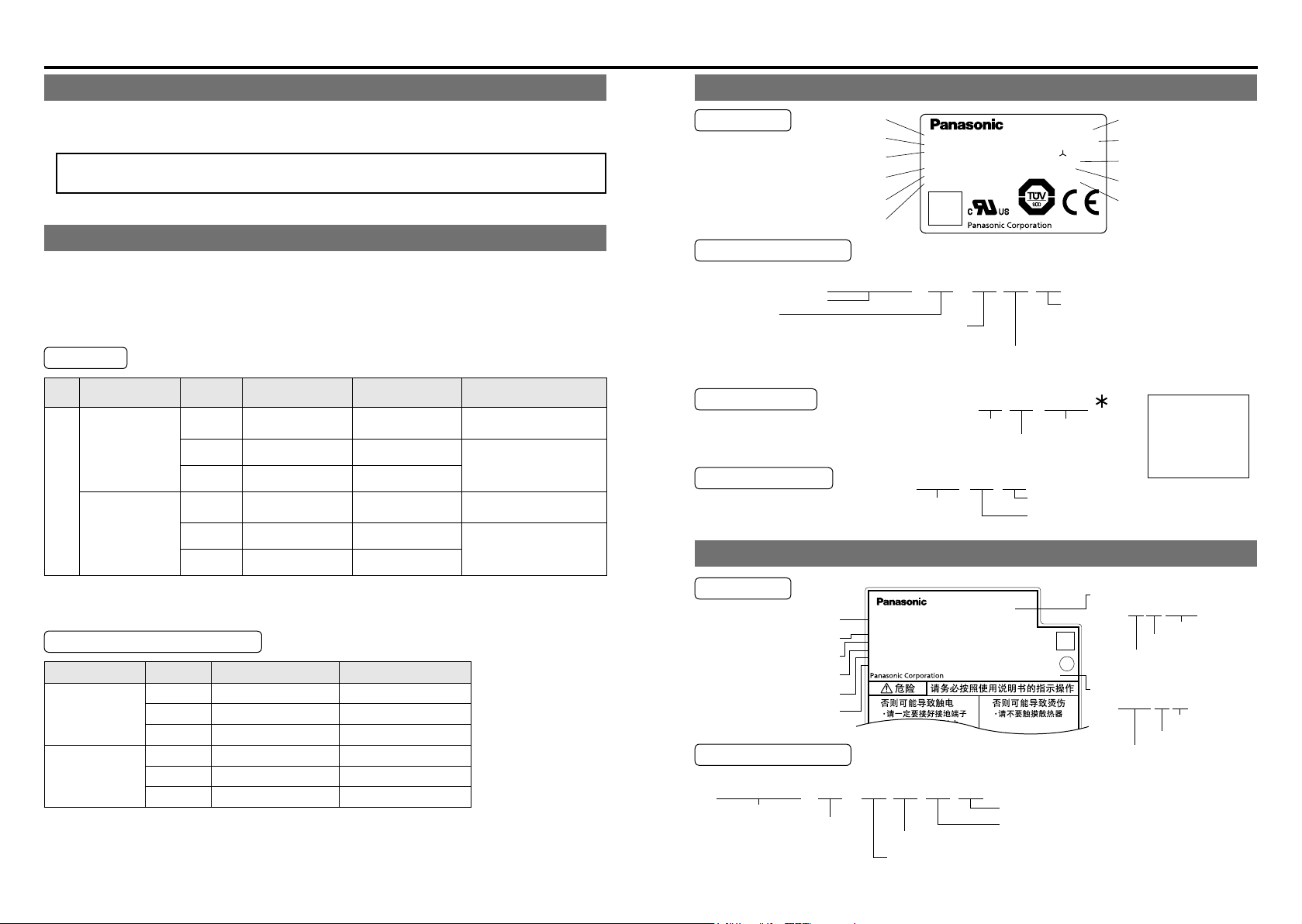
Checking the model of brushless motor
Nameplate
Model No.
Rated input voltage
Rated output
Rated frequency
Rated speed
BRUSHLESS MOTOR
MBMU5AZAX
Model No.
INPUT 3Φ AC
RATED OUTPUT
RATED FREQ.
RATED REV.
0– 240
3000
0.53
50
200
r/min
V
A
W
H z
Model designation
Output
5A: 50 W
9A: 90 W
1E: 130 W
Type
Input power supply
1: 100 V
2: 200 V
Z: 100/200 V
Function
A: Standard
Serial number
Year of production
Production date
(Lower 2 digits of AD year)
2012 12 01Example)
Month of production
Year of production
(AD year)
Checking the model of brushless amplier
Nameplate
Model No.
Input/output voltage
Input/output phase
Rated input/output current
Input/output frequency
Rated output
Model designation
Compact geared
motor drive
Output
5A: 50 W
9A: 90 W
1E: 130 W
Function 1 B: with circuit for regenerative resistor
Input power supply 1: Single phase AC100 to 120 V
5: Single phase/3-phase AC200 to 240 V
P: Position control
Function 2 C: RS485 communication
0.16
S1(CONT.)
105(A)–UL
130(B)–TUV
TE,40°C
12120001N
20121201
IP65
Made in China
N·m
CONT.TORQUE
RATING
THERMAL
CONNECTION
SER. No.
Shaft specification
B: For gear head MB8G/MB9G
Consecutive number
Day of production
Month of production
Serial number
Ex.:
Production date
Ex.:
Year of production (AD year)
Thermal class
Serial number
Production date
Protection structure
The motor
manufactured
in Dec. 2012 is
given the Serial
number 0001.
P12120001*
Consecutive number
Month of production
Year of production
(Lower 2 digits of AD year)
20121201
Day of production
Month of production
O-ring (not provided on a round shaft model)
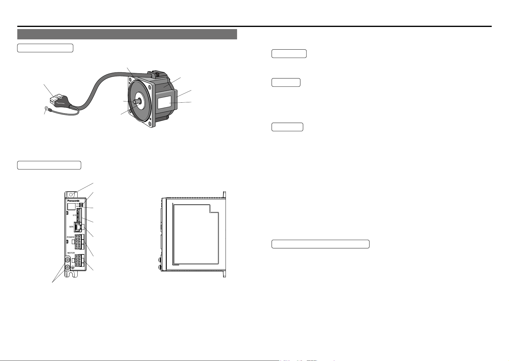
Name of part Installation
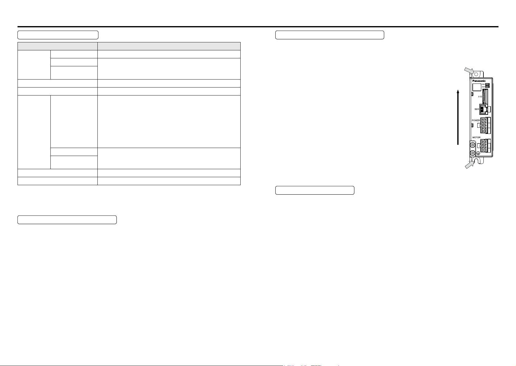
Name of part
Brushless motor
Connector for motor cable and
CS signal cable
Output shaft
Ground terminal
Oil seal
Brushless amplier
[Front view] [Side view]
Attachment hole
Power LED
(green: when power is ON)
Alarm LED
(red: when Trip is operation )
Connector for control signals
(I/O)
Connector for
communications
(SER)
Connector for power input
(POWER)
Connector for
motor connection
Grounding terminal screw
(MOTOR)
Safety precaution label
is affixed to the product.
Frame
Bracket B
Motor nameplate
Safety precaution label
is affixed to the product.
Install the brushless motor and brushless amplier properly for preventing failure
and accident.
Transport
• Use caution enough in transporting the unit to prevent injury by drop or fall, and avoid
damage to the equipment.
Storage
• Keep the unit indoors in a clean and dry place free from vibration with little change of
temperature.
• In keeping a gear head alone, direct the output shaft down.
(Otherwise, grease leaking is possible.)
Location
• Location gives great inuence upon the life of brushless motor and brushless amplier,
therefore choose a place in conformance with the conditions below:
(1) Indoors where the motor is not subjected to rain water and direct sun beam.
(2) Do not use the motor in corrosive atmosphere such as hydrogen sulde, sulfurous
acid, chlorine, ammonia, sulfur, gas chloride, gas sulde, acid, alkali, and salt, in the
atmosphere of combustible gas, or in the vicinity of ammables.
(3) Place not exposed to grinding liquid, oil mist, iron powder, and cutting particle.
(4) Well-ventilated place with little moisture, oil, or inundation, and place far from heat
source such as a furnace.
(5) Place easy to check and clean
(6) Place free from vibration
(7) Do not use the unit in an enclosed environment. Enclosing may raise the temperature
of motor (amplier), and shorten their life.
Caution in installing gear head
Install a device that will ensure safety operation of the system even if the following
failures should occur on the life end of gear head: idling by damaged teeth, locking
by bite, grease leakage, and the like.
As for application such as on a lifter or the like device, install a device for preventing drop
•
by damaged teeth.
As for application such as opening and closing of door, install a release device against
•
locking by gear biting.
As for food or textile equipment, install an oil pan for measures against grease leakage.
•
Do not install an encoder, sensor, contact, etc., in the proximity of gear head. Or
•
otherwise, protect such devices against grease leakage.
• In order to prevent unexpected accident, be sure to perform daily check.
-9--8-
Installation
Location of
Installation/ Caution
Environmental condition
Item Condition
Brushless motor –10 ℃ to 40 ℃ (free from freezing)
Ambient
temperature
Storage temperature At normal temperature and normal humidity
Protection
structure
Brushless amplifier
Digital key pad
(Option)
Ambient humidity 20% to 85% RH (free from condensation)
(Excluding shaft pass-through section and lead wire connector)
This motor meets test requirements specied in EN
•
Brushless motor
standards (EN60529 and EN60034-5). This motor
0 ℃ to 50 ℃ (free from freezing)
IP65
cannot be used for an application that requires long
term waterproof performance, such as the case where
the motor is always washed with water.
Brushless amplifier
Digital key pad
(Option)
Vibration Not greater than 4.9 m/s2 (10 to 60 Hz)
Altitude Not greater than 1000 m
Equivalent to IP20
*1 Ambient temperature is measured at a distance of 5 cm from the product.
*2 Temperature which is acceptable for a short time, such as during transportation,
is –20 ℃ to 60 ℃ (free from freezing).
Installation of brushless motor
• Oil and water protection
(1) Direct down the lead of cable as far as possible.
(2) Avoid use in such an environment where the motor is always exposed to oil and water.
(3) Avoid use with cable immersed in oil or water.
• Stress to cable
(1) Make sure that stress is not applied to the lead or connection of cable due to bending
or dead weight.
(2) In installation where the motor moves, x the cable of motor, and house the extension
cable connected to it in the cable bear to reduce stress by bending as small as
possible.
(3) Allow the bending radius of cable as large as possible.
Installation of brushless amplier
The amplier is a vertical placement type. Install it vertically and provide at least
*1
*1
*2
10 cm space around it for ventilation.
(1) When installing with screw
Determine the fastening torque of the fixing screw
based on the strength of the screw and material of
the mounting surface, to ensure secure and safe
fixing screw
installation.
Example) To install to steel plate with steel screw (M4):
1.35 to 1.65 N・m
(2) When installing to DIN rail
The DIN rail mounting unit is available as option.
For details, refer to P.106.
Vertical
Location of
fixing screw
Cautions for Proper Use
(1) Because the control circuit is sensitive to temperature and impact, read this instruction
manual carefully for proper installation.
(2) The brushless amplifier switches the power element at a high speed to control the
motor. When the motor runs, leaking current will increase, which may activate the
leakage breaker. If this is the case, use a leakage breaker provided with measure
against high frequency for inverter.
-11--10-
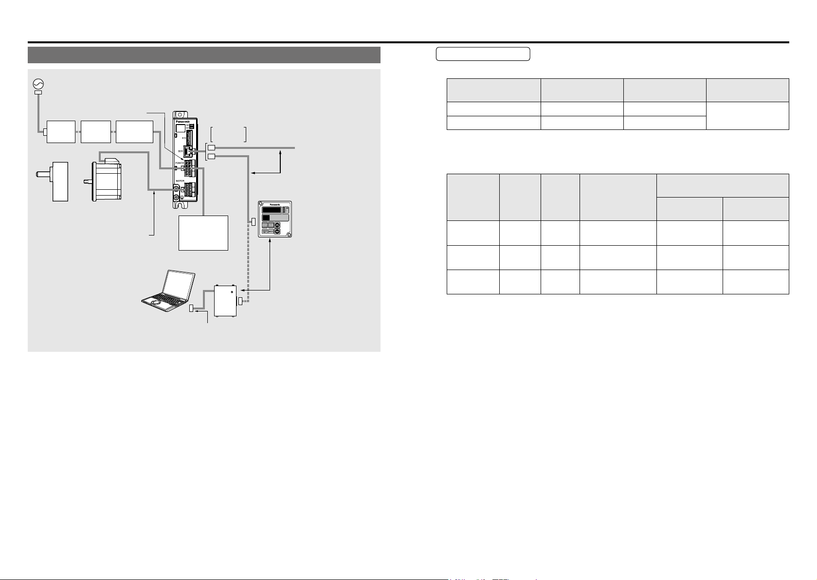
System conguration and wiring System conguration and wiring
System conguration/ general wiring diagram
AC power supply
Power supply connection
connector kit
MCCB
Gear head
(option)
Motor extension cable
Select if needed (to 10 m).
Communication software
PANATERM for BL
Please download from our web site
Change of parameter seting
monitor of a control state
Noise
filter
GP series
Brushless motor
(option)
Magnetic
contactor
(option)
Personal computer
(Customer preparation)
• Wiring work shall be performed by qualied electric engineering technician.
• Do not turn on power before nishing wiring, to avoid risk of electric shock.
• For details of options (sold separately), see P.102.
GP series
Brushless amplifier
Connector
for SER.
External
regenerative
resistor
(Option)
If your PC does not have RS232 port,
use RS232-USB converter.
RS485
It cannot be used
simultaneously.
Digital key pad connecting cable
(option)
Digital key pad
(option)
Digital display console.
It enables change of
parameter.
(refer to P.18)
It cannot be used
POWER
simultaneously.
PC connecting cable (option)
Wiring equipment
• Recommended noise lter
Voltage
Single phase 100, 200 V DV0P4170 SUP-EK5-ER-6
3-phase DV0PM20042 3SUP-HU10-ER-6
Optional part
number (option)
• Selection of Molded Case Circuit Breaker (MCCB), magnetic contactor, and electric wire
(wiring within equipment) (refer to P.91 “Conformance to EC directive and UL standard”
for compatibility with overseas standard.)
Magnetic
contactor rated
)
current
(contact structure)
Voltage
Single phase
100V
Single phase
200V
3-phase
200V
Capacity
(W)
50 to 130 5 A 20 A (3P+1a) 0.5 (AWG20) 0.13 (AWG26)
50 to 130 5 A 20 A (3P+1a) 0.5 (AWG20) 0.13 (AWG26)
50 to 130 5 A 20 A (3P+1a) 0.5 (AWG20) 0.13 (AWG26)
MCCB
rated
(
current
■ Be sure to ground the grounding terminal.
In wiring to power supply (outside of equipment) from MCCB, use an electric wire of 1.6
mm
diameter (2.0 mm2) or more both for main circuit and grounding. Apply grounding
class D (100 Ω or below) for grounding. Do not tighten the ground wires together, please
tighten them individually.
Selection of relay
•
As for use for control circuit such as control input terminal, use a relay for small signal
(minimum guarantee current 1 mA or less) for preventing poor contact.
<Reference example>
Panasonic: DS type, NK type, HC type, OMRON: G2A type
Control Circuit Switch
•
When using a switch instead of relay, use one for minute current in order to prevent poor
contact.
<Example>
Nihon Kaiheiki Ind.Co.,Ltd: M-2012J-G
Manufacturer's
part No.
Electric wire (mm
(Wiring within equipment)
Main circuit/
Grounding wire
Manufacturer
OKAYA ELECTRIC
IND. CO., LTD.
2
)
Control circuit
-13--12-
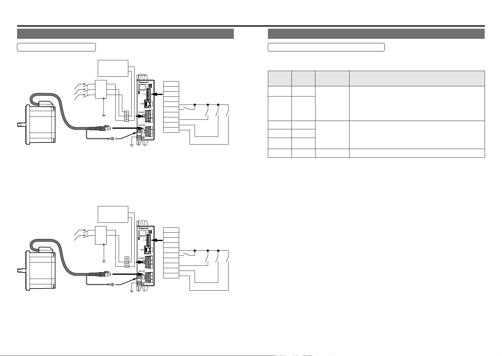
Wiring
• In case of 3-Phase 200 V
Run start
Run start
Wiring
Standard wiring diagram
Power
supply
input
In wiring to power supply (outside of equipment) from MCCB, use an electric wire of
1.6 mm diameter (2.0 mm
Apply grounding class D (100 Ω or below) for grounding.
Do not tighten the ground wires together, but connect them individually.
Fastening torque of earth screws to be 0.49 to 0.98 N·m.
• In case of single phase 100, 200 V
Power
supply
input
MCCB
Molded Case
(
Circuit Breaker
Grounding
2
) or more both for main circuit and grounding.
MCCB
Molded Case
(
Circuit Breaker
Grounding
External
regenerative
resistor
Noise
L1
filter
L2
L3
)
Be sure to ground the grounding terminal.
External
regenerative
resistor
Noise
L1
filter
L2
)
Brushless
amplifier
156
10
Brushless
amplifier
156
10
Connector
for control
signals (I/O)
+5V
(NC)
GND
(NC)
Connector
for control
signals (I/O)
+5V
(NC)
GND
(NC)
02
01
I4
I3
I2
I1
02
01
I4
I3
I2
I1
10
Forced trip
1
10
Forced trip
1
Point designation
Home sensor
Point designation
Home sensor
Function of terminal
Connector for power supply (POWER)
Connector on amplier side: Part No. 5569-10A1-210 (Molex Inc.) or equivalent.
(mating connector: Housing 5557-10R-210, Terminal 5556PBTL)
Terminal
number
1,2,4,7,9 NC
Terminal
symbol
3 B
5 P
6 L3
8 L2
10 L1
Terminal
name
Terminal for
external
regenerative
resistor
Terminal for
power supply
input
-
Terminal explanation
Please connect external regenerative resistor of an option
if needed.
External regenerative resistor name:
100 V type DV0P2890 (50 Ω)
200 V type DV0PM20068 (200 Ω)
Connect the terminal to commercial power supply
conforming to voltage specication. When you use single
phase, connect the main power between L1 and L2
terminals.
Do not connect anything.
Be sure to ground the grounding terminal.
In wiring to power supply (outside of equipment) from MCCB, use an electric wire of
1.6 mm diameter (2.0 mm
2
) or more both for main circuit and grounding.
Apply grounding class D (100 Ω or below) for grounding.
Do not tighten the ground wires together, but connect them individually.
Fastening torque of earth screws to be 0.49 to 0.98 N·m.
-15--14-
Wiring
Input circuit
Connector for control signals (I/O)
Connector on amplier side: Parts No. S10B-PASK-2 (J.S.TMfg.,Co.,Ltd.) or equivalent.
mating connector: Representative Housing PAP-10V-S,
(
Terminal SPHD-001T-P0.5 or SPHD-002T-P0.5
Terminal
*1 Function of input/output can be changed by the Digital key pad or PANATERM for BL.
*2 Maximum rated voltage: –0.5 to 5.5V.
Terminal
number
1
2
3
4 (NC)
5
6 GND
7 (NC)
8 +5V
9 01
10 02
Connector for control signals pin number is 1, 2, ... 10 in the order from grounding terminal side.
•
•
Permissible length for control signal cable is 5m or less.
symbol
*1
I
1
*1
I
2
*1
I
3
*1
I
4
※1
※1
Terminal
name
Signal
input 1
Signal
input 2
Signal
input 3
— —
Signal
input 4
Control
ground
— —
Power
supply
Signal
output 1
Signal
output 2
Default Terminal explanation
Run start
Point
designation
Home
sensor
Forced trip
—
—
Trip output
In-motion
signal
In turning on signal, short between
“I1” and “GND”.
In turning on signal, short between
“I2” and “GND”.
In turning on signal, short between
“I3” and “GND”.
Do not connect anything.
In turning on signal, short between
“I4” and “GND”.
Common ground terminal for control
signal.
Do not connect anything.
Set 50 mA or below
Open collector output.
Open collector Vce max: DC30 V,
Ic max: 50 mA
Open collector output.
Open collector Vce max; DC 30 V,
Ic max; 50 mA
)
*2
*2
*2
*2
function
selection
Pr50 Pr54
Pr51 Pr55
Pr52 Pr56
Pr53 Pr57
Pr5C Pr5E
Pr5d Pr5F
logic
selection
— —
— —
— —
— —
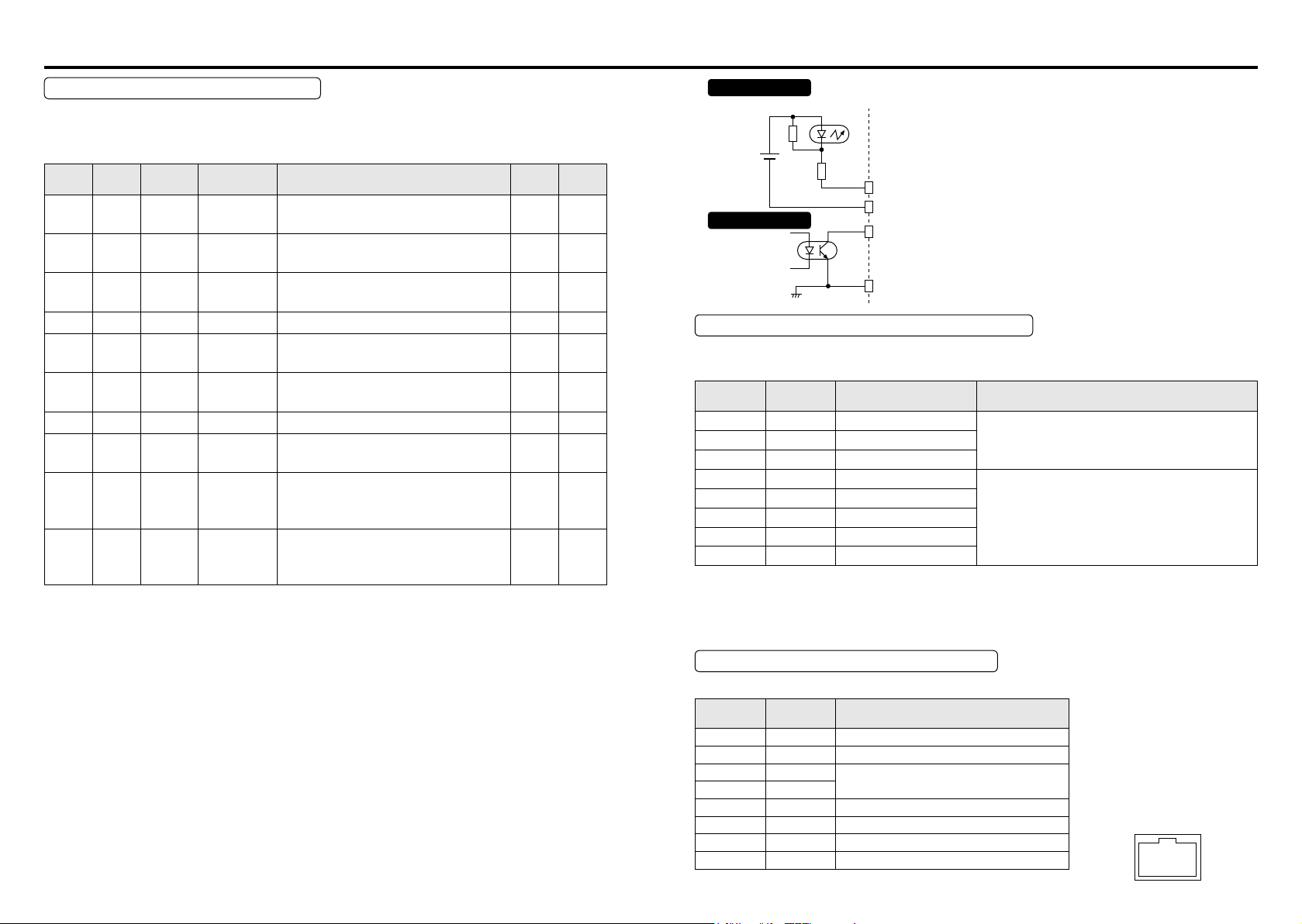
Photo-coupler
Internal
power
supply
(+5 V)
Output circuit
1 kΩ
I1, I2, I3, I4
GND
01, 02
Vce max DC30 V
Ic max 50 mA
GND
Connector for motor connection (MOTOR)
Connector on amplier side: Parts No. 5569-08A1-210 (Molex Inc.) or equivalent.
(mating connector: Housing 5557-08R-210, Terminal 5556PBTL)
Terminal
number
1 U Motor U phase
3 W Motor W phase
4 5VS High voltage 5 V
5 CS1 CS signal 1
6 CS2 CS signal 2
7 CS3 CS signal 3
8 GNDS High voltage GND
•
High voltage is applied to motor wire and CS signal line; Use caution for avoiding electric shock.
Terminal
symbol
Terminal name Terminal explanation
Connect motor wire U, V and W.2 V Motor V phase
Not isolated from commercial power source.
Use care to avoid electric shock and
grounding fault.
• Use a motor extension cable (option) for extending motor wire.
• No.4 to 8 terminals of option cable are shielded, But the shield material is not grounded.
please do not ground the shield material in order to avoid malfunctions or damages.
Connector for communications (SER)
Modular jack: 85503-0001 (Molex Inc.) or equivalent (RJ45
Terminal
number
1 — Do not connect anything.
2 +5V
3 SOT
4 SIN
5 RS485+ For connect RS485+
6 RS485− For connest RS485–
7 GND
8 SCK Interface for Digital key pad
Terminal
symbol
Terminal explanation
DC5 V power supply for Digital key pad
Interface for Digital key pad or
PANATERM for BL
Power supply GNG for Digital key pad
-17--16-
)
• Connection of Digital key
pad of an option is possible.
Digital key pad connecting
cable of an option
(DV0P383**) is required.
• The terminal number of a
modular jack is the below
gure
8 1
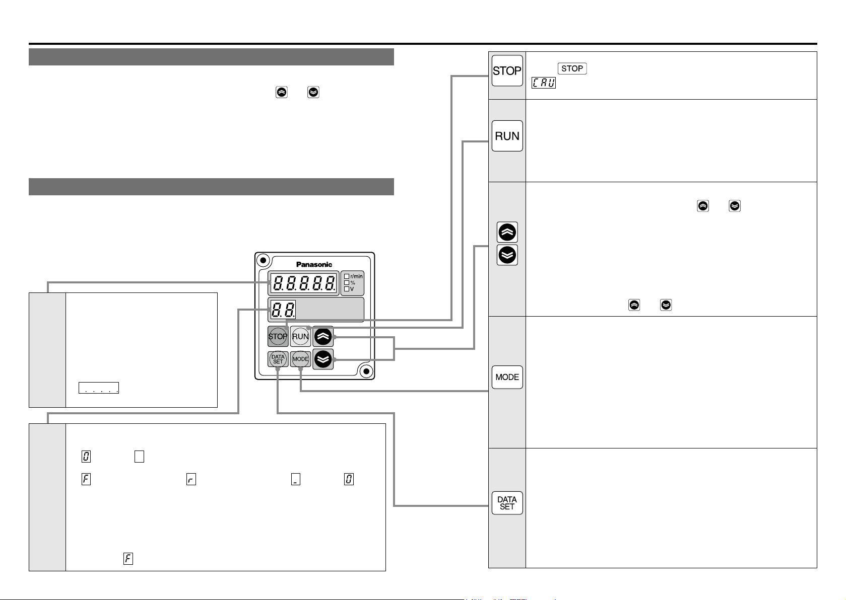
How to use Digital key pad (option)
Function of Digital key pad
• Monitoring of rotation speed (actual speed) and load factor, etc.
• Display detail of trip, and trip history. Trip reset by pressing
• Parameter setting, initialization, and copying function.
• Teaching function (Target point (positioning point) can be set by actually starting the
motor.)
■ When using Digital key pad, the Digital key pad connection cable (DV0P383**/
option) is required.
Using the Digital key pad
• When power is turned on, rotation speed (actual speed) r/min is displayed in monitor
mode (changeable by Pr7A).
• Displayed value is an index. Do not use the Digital key pad for a measuring instrument.
■
In monitor mode
Displays rotation speed (actual
speed), commanded speed, present
position, trip history, and the like.
■
5-digit
LED
2-digit
LED
In parameter editing
Displays a parameter setting value.
■
In teaching
Displays present position of motor.
•
a negative value.
■
In monitor mode
The left value (position of 10) indicates an operation command signal status.
(
The right value (position of 1) indicates a rotation direction and operation status.
( : Operating in direction +*, : Operating in direction –*, : Stand still, : Motor
is free)
■
In parameter editing
Displays the number of parameter.
■
In teaching
Displays the point number of parameter.
• Rotation direction is changed by Pr23.
Direction + (
is displayed for indicating
: Stand still, : Commanding)
): CCW rotation when viewed from motor output shaft (default).
and .
Switch
Switch
Switch
Switch
Switch
When
switch is pressed, the setting change warning
(CAU) is displayed, and the motor is stopped and tripped.
■
In monitor mode
When this switch is pressed for about 4 seconds, system shifts to
teaching mode.
■
In teaching
When homing is not completed, homing operation is executed by
pressing this switch for about 4 seconds in teaching mode.
■
In monitor mode
Trip reset can be executed by pressing
and at the same
time.
■
In parameter editing
This switch allows selection of parameter, and setting and changing
of details.
Parameter changes continuously while this switch is held down.
■
In teaching
When homing is completed, teaching operation (motor drive) is
enabled by the switch
■
In monitor mode
and .
Switch for changing monitor mode. Whenever this switch is pressed,
the mode changes in this sequence:
Rotation speed (actual speed) → Internal DC voltage (voltage of
smoothing capacitor in power supply) → Load factor → Torque →
Commanded speed → Present position (lower 5 digits)
→
Present position (shaft rotation number) → Rotation speed (actual
speed) → ....
■
In parameter editing, and in teaching
System shifts to monitor mode. (Setting is not saved in EEPROM.)
■
In monitor mode
System shifts to parameter number mode.
■
In parameter editing
This switch is for changing parameter number mode and parameter
setting mode, and for saving parameter setting in EEPROM.
■
In teaching
This switch is for changing point number mode and teaching mode,
and for saving setting in EEPROM (nonvolatile memory built in the
amplier).
-19--18-
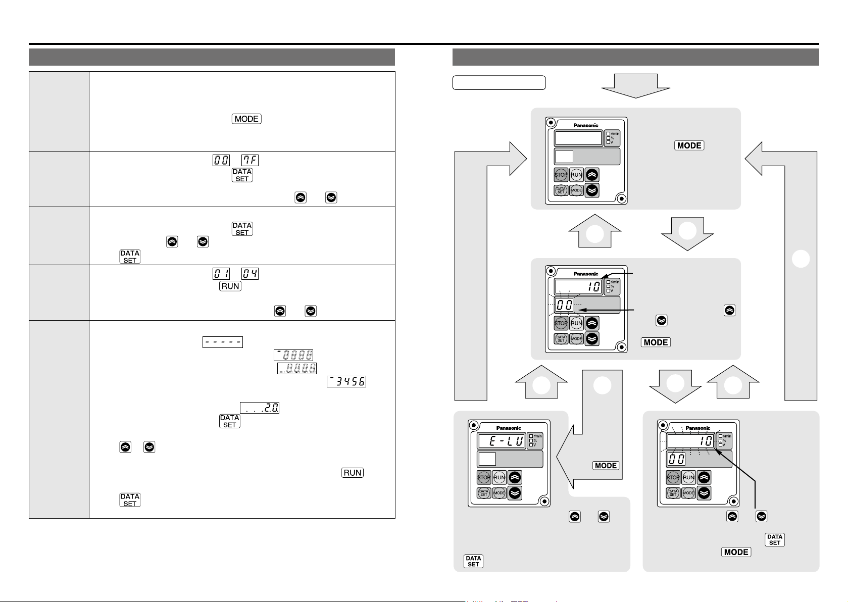
How to use Digital key pad (option)
Description of various modes
Displays rotation speed (actual speed), commanded speed, internal DC
voltage, load factor, torque, and present position on 5-digit LED. This mode is
Monitor mode
Parameter
number mode
Parameter
setting mode
Point number
mode
Teaching
mode
<Information>
Present position is the distance from the home, indicated in pulses (288 pulses/rotation).
set when power is turned on.
Control changes to this mode when
number mode, parameter setting mode, point number mode, and point setting
mode.
Displays a parameter number ( to ) in ashing.
Control changes to this mode when
number mode.
Parameter number can be changed and selected by
Displays the detail of parameter (setting) in ashing.
Control changes to this mode when
Change setting by
When
Displays a parameter number ( to ) in ashing.
Control shifts to this mode when
monitor mode.
Point number can be changed and selected by
Displays the present position of motor (distance from home)
(If homing is not completed,
• When present position is greater than 99999,
• When present position is smaller than -99999,
Ex. 1) When present position is 123456, only lower 4 digits
Ex. 2) When present position is -20,
Control shifts to this mode when
mode.
When
be operated.
If homing is not completed yet, homing operation is started when
is pressed for 4 seconds.
When
point setting, and saved in EEPROM
switch is pressed after change of setting, it is saved in EEPROM.
displayed.
or switch is pressed after completion of homing, the motor can
switch is pressed, the present position is set in parameter as a
and switch.
switch is pressed in parameter
switch is pressed in parameter
and switch.
switch is pressed in monitor mode.
switch is pressed for 4 seconds in
and switch.
in ashing
is displayed.
is displayed.
is displayed.
is displayed.
switch is pressed in point number
switch
.
are
Operation of the Digital key pad
Basic operations
Monitor mode
MODE
Trip
reset
Flashing
DATA
SET
Parameter number mode
MODE
Trip detail display mode
When trip
occurs, trip
display mode is
set by
switch.
• Trip can be reset by pressing and
switch at the same time.
Display shifts to monitor screen after resetting.
• Shifts to parameter number made when
switch is pressed.
Power-on
• Changes display on 5-digit
LED with switch.
Displays monitored details set by Pr7A
(see P.45).
DATA
SET
Displays the contents of
displayed parameter (setting).
Displays parameter number.
• Number is changed by
and switch.
• Exit this mode with
switch (returns to
monitor).
DATA
SET
Parameter setting mode
Flashing
• Value is changed by and switch.
(Such value is effective on the spot.)
• Value is written in EEPROM by switch.
• Exit this mode with switch without
writing in EEPROM.
MODE
DATA
SET
-21--20-
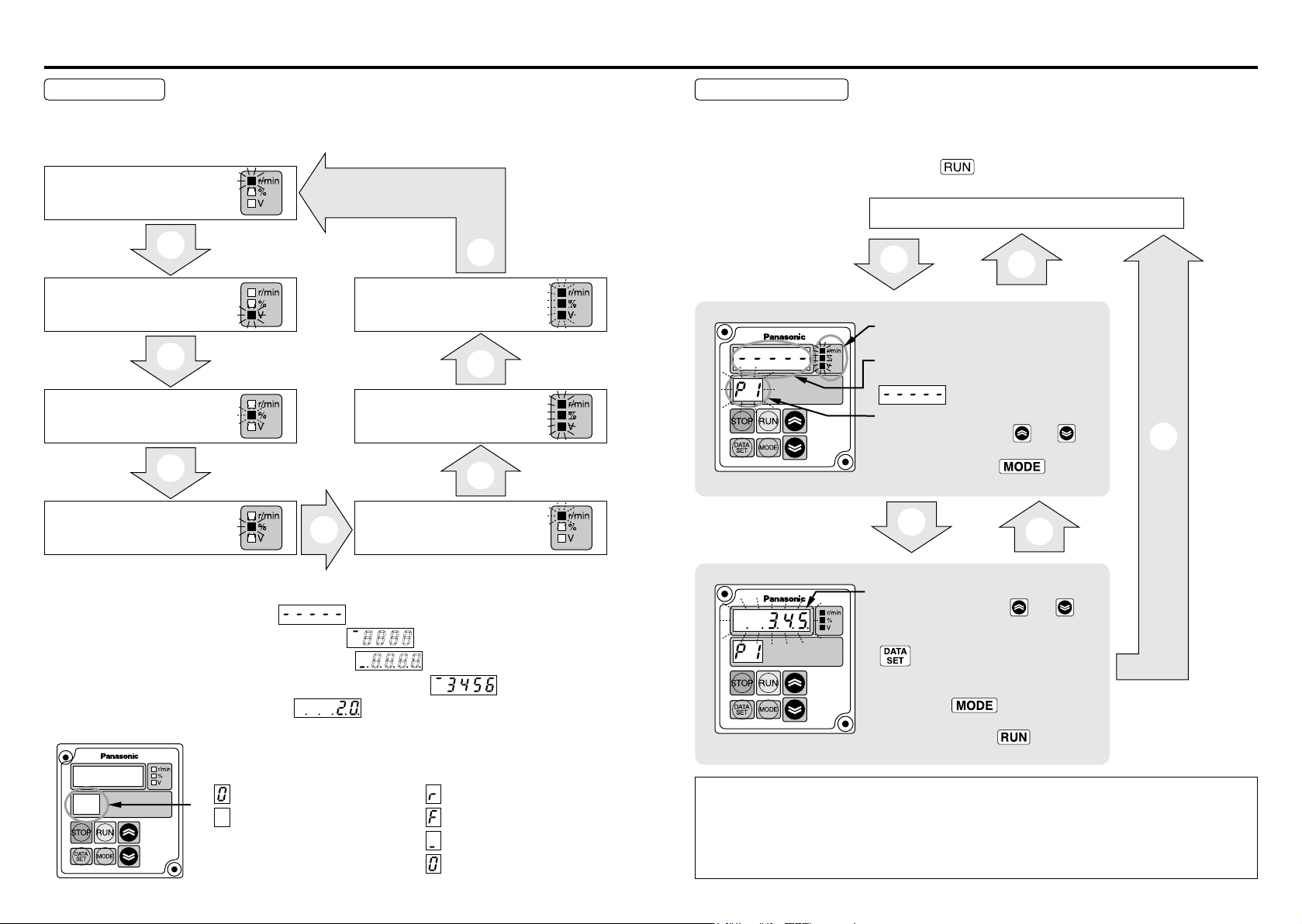
How to use Digital key pad (option)
Monitor mode
Monitor display item can be changed after power is turned on and when monitor mode
display is on. (See P.45 for setting of Pr7A.)
Rotation speed
(actual speed) display
MODE
Internal DC voltage display
(Voltage of smoothing
capacitor in power supply)
MODE
Load factor
(average torque)
display
MODE
Torque display
Display of present position
• When homing is not completed, is displayed.
• When present position is greater than 99999, is displayed.
When present position is smaller than –99999, is displayed.
Ex. 1) When present position is 123456, only lower 4 digits are displayed.
Ex. 2) When present position is –20, is displayed.
Lights
up.
Lights
up.
Flashing
Lights
up.
MODE
Left (position of 10)
... Displays command status.
: Stand still
: In Motion (BUSY)
MODE
Present position
(shaft rotation
number)
flashing
MODE
Present position
(Lower 5 digits)
All light
MODE
Flashing
Commanded speed display
Right (position of 1)
... Displays rotation direction.
: Running in − direction.
: Running in + direction.
: Stand still
: Motor is free.
All
up.
Teaching function
This motor allows two target position setting methods, one of which is setting by parameter value, and the other is setting target position by actually operating the motor by use of
teaching function.
In order to use teaching function, press
switch for 4 seconds or longer on the monitor
mode display screen, then control shifts to point number mode of teaching function.
Monitor mode
Hold down for 4 seconds.
RUN
MODE
Point number mode
All units light up.
Flashing Flashing
Displays present position (lower 5 digits).
When homing is not completed,
is displayed.
Point number (to be set)
• Number is changed by and
switch.
• Exits this mode with switch
(returns to monitor).
DATA
SET
DATA
SET
MODE
Teaching mode
• When homing is completed, execute
teaching operation with and
switch (motor operation).
• Set the present position on the point with
switch.
(Also writes in EEPROM.)
Display returns to monitor screen without
setting when switch is pressed.
• When homing is not completed, homing
operation is started if switch is held
down for about 4 seconds.
[Caution]
• In teaching mode, displayed present position is set as target position.
• Set the point coordinate setting to absolute travel. (Pr02, 0A, 12, and 1A).
When the point coordinate setting is set to relative travel, stop position is different between
teaching setting and actual operation.
• In point number mode and teaching mode, operation instruction by I/O or RS485 is not accepted.
-23--22-
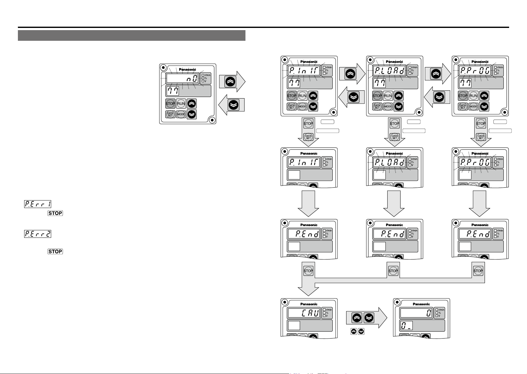
How to use Digital key pad (option)
Data initialization
Parameter reading
Parameter writing
Parameter copy function
Parameter copy function (Digital key pad ←→ Brushless amplier) can be used by Pr77.
• Initializing the data of the Digital key pad
EEPROM installed onboard the Digital
key pad is initialized (data cleared).
When reading is disabled, or when data
All flashing
on display
transfer fails during copying, execute
“Data initialization of the Digital key pad”.
Normally, it is not required.
• Reading parameters
Parameter of Brushless amplier is read and saved in EEPROM of the Digital key pad.
Read parameter is retained even when the Digital key pad is separated from the Brushless amplier.
• Writing parameters
Parameter information saved in the Digital key pad is written to the Brushless amplier.
(Saved in EEPROM of Brushless amplier)
<Information>
• Error in copying parameters
→ Press
: Data trouble was found during copying
switch for clearing, and then copy the parameter again. If data trouble is
still found, initialize the Digital key pad and try again.
of Digital key pad
+
All flashing
on display
Process
completed
STOP
+
DATASET
Hold down
(for about
1 second).
For about
30 seconds
(Amplifier → Digital key pad)
+
All flashing
on display
Process
completed
STOP
+
DATASET
Hold down
(for about
1 second).
For about
30 seconds
(Digital key pad → Amplifier)
+
All flashing
on display
Process
completed
STOP
+
DATASET
Hold down
(for about
1 second).
For about
10 seconds
: Copy error
→ This error occurs in the attempt to copy data between products with different function.
Press
switch to cancel the error.
Although parameters can be copied between the same models with different output,
parameters should be copied between the same outputs in principle.
<Note>
Do not turn off power or disconnect the connection cable of Digital key pad during operation such as “Initializing data of Digital key pad”, “Reading parameter into Digital key pad”,
“Writing parameter to brushless amplier”, etc.
Trip reset
Press both at
the same time.
Normal condition
-25--24-
<Information>
Parameters that are
effective after power
resetting become
effective when power
is cut off once and
turned on again.
Test run
Inspection before Test run
1) Make sure that all wiring is correct.
2) Make sure that input power supply conforms to rating.
Test run
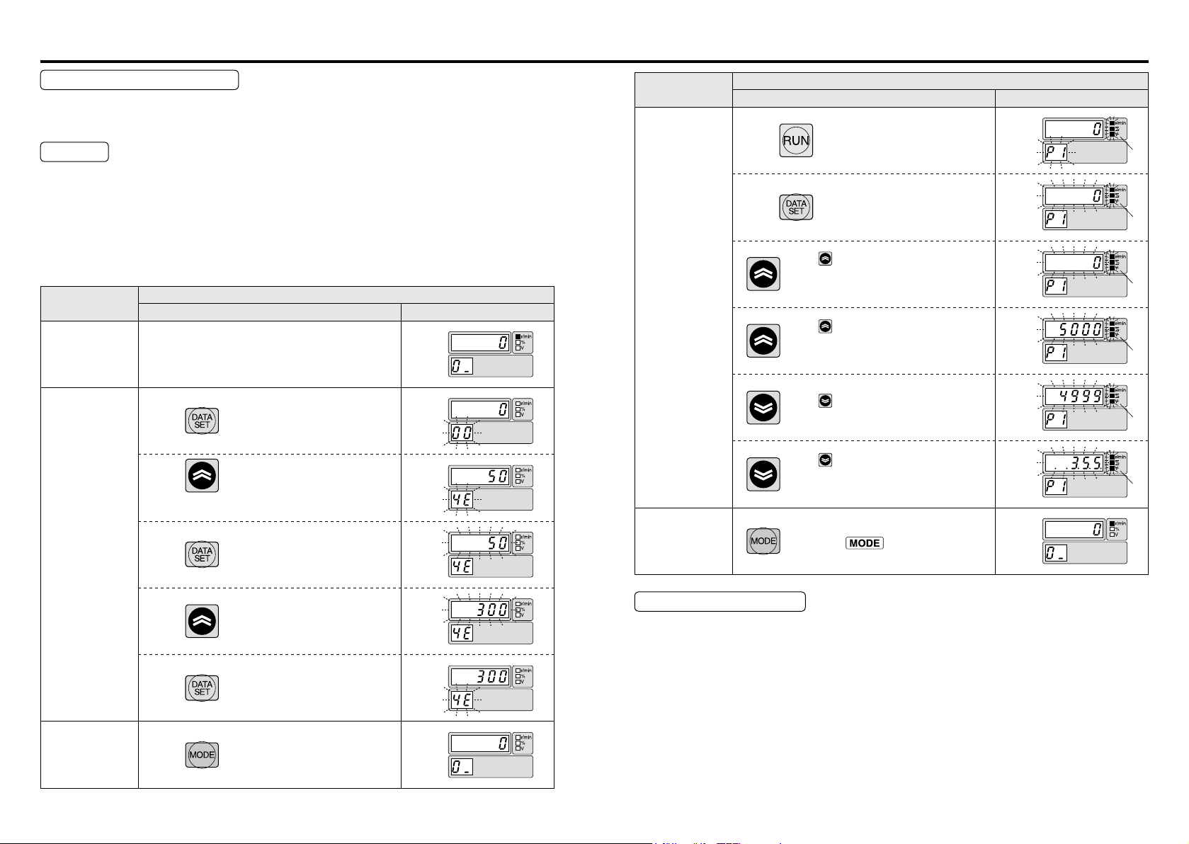
Procedure for test run using the Digital key pad is as follows:
Shown here is the case of running at 300r/min in direction CW or CCW by use of teaching
function.
First execute the following work for safe operation.
[1] Ensure that the motor alone can be operated.
[2] Turn on power and follow the steps below for test run.
Description of
operation
1.Turn on power
2.Set the action
Pr4E
Setting of
(
teaching speed
Switch LED display
Press
)
Press and choose parameter 4E
(teaching speed).
(Initial setting: 50)
Press
Operation panel
Flashing
Flashing
Flashing
Description of
operation
4.Teaching
operation
5.Exit
Operation panel
Switch LED display
Press for 4 seconds
Press
When is pressed in this condition, the
motor rotates in + direction* and 5-digit
LED indicates position coordinates.
When is released, the motor stops.
(LED display "5000" is an example, which
shows the present position of the motor.)
When is pressed after the motor has
stopped, the motor rotates in one direction.
When is released, the motor stops.
(LED display ". . 3.5.5." indicates that
the present position is –355.)
When exiting the mode without setting
data, press switch to return to
monitor mode.
All light up. All light up. All light up. All light up. All light up. All light up.
Flashing
Flashing
Flashing
Flashing
Flashing
Flashing
3.Return to
monitor mode.
Press and change the teaching speed to 300.
Press
Press
Flashing
Flashing
Checkpoint in Test run
[1] Check whether the motor rotates smoothly. Check for abnormal noise and vibration.
[2] Check whether the motor is accelerated and decelerated smoothly.
[3] Make sure that the direction of motor rotation is correct.
* Rotation direction + represents CCW on the motor shaft in default setting. (Can be
changed by Pr23 coordinate system setting.)
Rotation direction of gear head output shaft may sometimes be reversed due to re-
duction gear ratio when gear head is installed.
(See the table of permissible shaft torque on P.29. Rotation direction is described.)
-27--26-
Checking load and use condition
Standard life
Overhung load (W)
Check the use condition for extended use of the product. Particular use conditions may
lead to heating or damage to the shaft. Fully check use conditions, and use the motor in a
permissible range.
Standard life
Standard life is 10,000 hours for the motor equipped with gear head (MB8G and MB9G).
(Standard life of sealing performance of oil seal is 5,000 hours.)
Standard life refers to design life for operation 8 hours per day (service factor: Sf = 1.0) at
a normal temperature and humidity, under uniform load (permissible shaft torque of gear
head and rated torque of motor).
* Standard life in the case of 3000 to 4000 r/min rotation speed of the motor, please
calculated by the following formula.
Standard life (hours) = 10000 (h) × 3000 (r/min) / rotation speed (r/min)
<Information>
Repeated forward/reverse operation with motor shaft rotation angle below 45 degrees
causes fretting of bearing (partial wear due to bearing out of grease), and is not advisable.
It does not apply if operation is available to rotate the motor shaft above 45 degrees at an
appropriate interval more than once a day.)
Oscillation due to inappropriate setting of gain, also causes fretting.
Note that gear head shaft is also subject to this restriction.
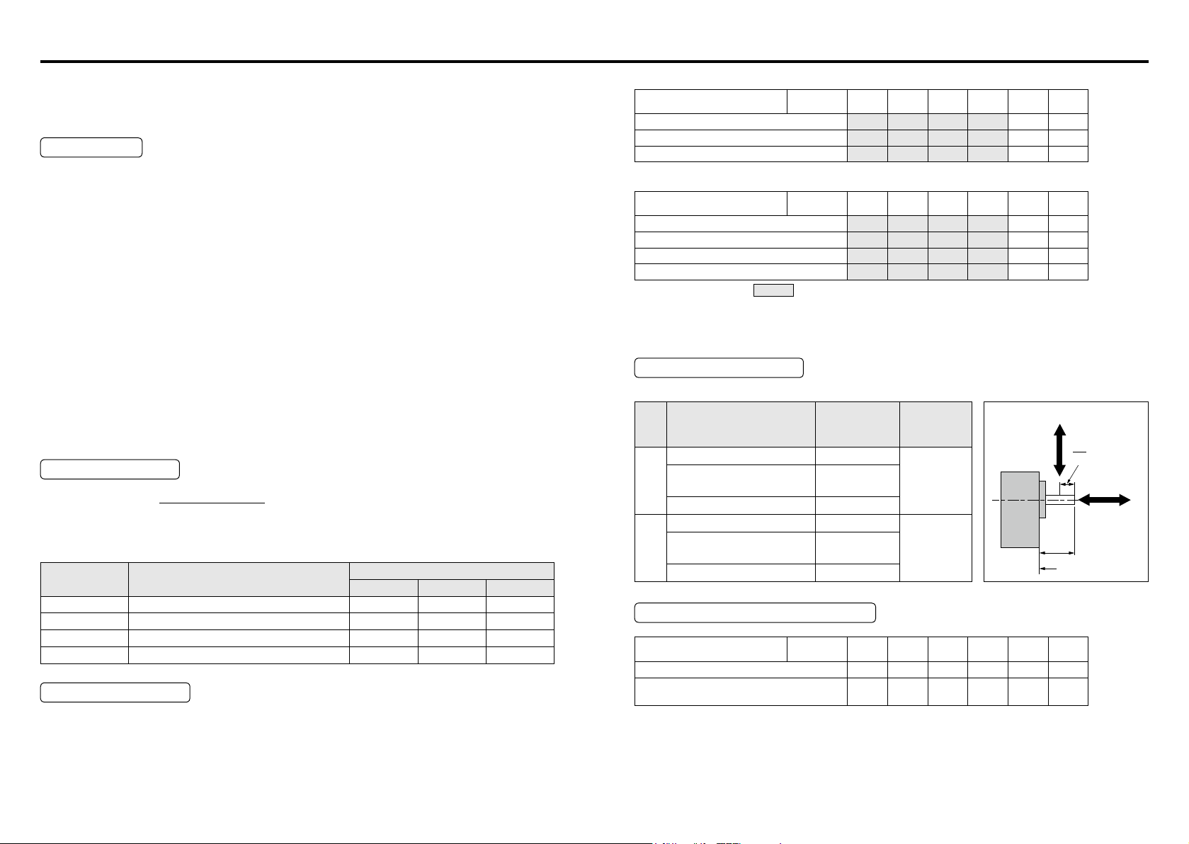
Service factor (Sf)
Life expectancy =
Service factor (Sf) varies with impact of load and operation time. The table below shows
how the service factor value depends on load condition.
Type of load Typical load
Constant Belt conveyor, One-directional rotation 1.0 1.0 1.5
Light-impact Start/Stop, Cam-drive 1.2 1.5 2.0
Medium-impact Instant FWD/REV, Instant stop 1.5 2.0 2.5
Heavy-impact Frequent medium-impact 2.5 3.0 3.5
Service factor (Sf)
Service factor
5 hours/day 8hours/day 24hours/day
Permissible torque
The required gear head allowable shaft torque TA can be determined based on the service
factor and actual load torque T
A
T
= T1 × Sf
Select a gear head/motor so that the required torque (continuous value) is equal to or lower
than the allowable shaft torque shown in the table below.
1
.
• Motor rotation speed: 3000 r/min or less.
Model name
MBMU5AZAB/MB8G□BV
MBMU9A○AB/MB9G□BV
MBMU1E○AB/MB9G□BV
Reduction
ratio
5 10 15 20 30 50
0.71 1.4 2.2 2.8 4.0 6.8
1.2 2.5 3.6 4.9 7.0 11.6
1.9 3.7 5.6 7.4 10.7 17.7
• Motor rotation speed: 3000 to 4000 r/min or less.
Model name
MBMU5AZAB/MB8G□BV
MBMU9A○AB/MB9G□BV
MBMU1E1AB(100 V)/MB9G□BV
MBMU1E2AB(200 V)/MB9G□BV
Reduction
ratio
5 10 15 20 30 50
0.53 1.1 1.7 2.1 3.0 5.1
0.90 1.9 2.7 3.7 5.3 8.7
1.1 2.1 3.3 4.3 6.2 10.3
1.4 2.8 4.2 5.6 8.0 13.3
Unit: N・m
Unit: N・m
* Direction of rotation: represents that the direction is same as that of motor;
otherwise opposite to that of motor
• ○ in the part name of motor represents either 1 or 2 which indicates supply voltage.
• □ in the part name of gear head represents a gure which indicates reduction ratio.
Shaft permissible load
The load should not cause the limits shown in the table below to be exceeded.
Gear
head
size
Model name
MB8G5BV
80
□
MB8G10BV, MB8G15BV
mm
MB8G20BV
MB8G30BV, MB8G50BV
MB9G5BV
90
□
MB9G10BV, MB9G15BV
mm
MB9G20BV
MB9G30BV, MB9G50BV
Permissible load inertia moment
Unit:×10−4kg・m
Model name
MBMU5AZAB/MB8G□BV
MBMU9A○AB/MB9G□BV
MBMU1E○AB/MB9G□BV
<Information>
• ○ in the part name of motor represents either 1 or 2 which indicates supply voltage.
• □ in the part name of gear head represents a gure which indicates reduction ratio.
Permissible
overhung load
Reduction
ratio
Permissible
thrust load
(W)
245 N
343 N
539 N
294 N
490 N
637 N
5 10 15 20 30 50
3.42 13.8 30.6 55.8 127 342
16.4 67.6 142 257 589 1684
-29--28-
(F)
Gear head
98 N
147 N
L
2
Thrust load
(F)
L
Attachment side
2
Assembling of gear head
Output shaft
Maintenance/ Inspections
Assembling of gear head
• Preparation for assembling
[1]
Gear head applicable to the motor described in this instruction manual is MB8G□BV
(for 50W) and MB9G□BV (for 90 W and 130 W). Never use a combination of gear
heads other than applicable ones. Failure to observe this instruction will result in
malfunction.
[2] Make sure that O-ring is attached to the bottom of spigot joint.
When the gear head is assembled with O-ring oating, it may result in grease leakage.
[3] When grease adheres to the end surface of gear head, wipe off clean.
If the gear head is assembled with grease adhered, it may cause grease to exude.
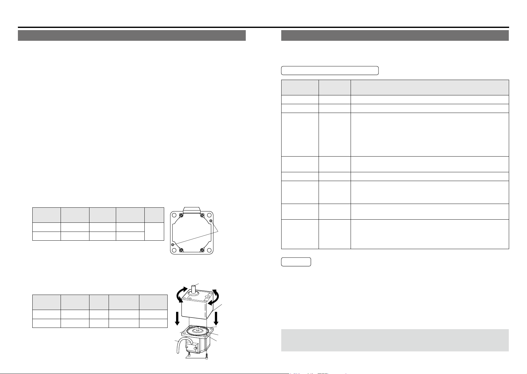
• Assembling
[1] Direct the motor pinion upward, and make sure that the relation between direction of
motor lead wire and output shaft matches with the equipment.
[2] Turn the motor pinion nely clockwise and counterclockwise for assembling, ensuring
that the tip of motor pinion does not hit the tooth of gear head.
<Information>
MB type gear head is provided with temporary assembling screw (two hexagon sock-
et head bolt). Before installing the equipment, assemble the motor and gear head
temporarily, which will ensure stable installation of the equipment. In installing to the
equipment, be sure to use four “mounting screws” attached to the gear head for se-
cure installation.
[Recommended tightening torque for temporary assembling]
Size
80 mm sq.
90 mm sq.
Gear head
type
MB8G M2.6 0.5 N・m
MB9G M3 0.8 N・m
Screw
size
Tightening
torque
Screw
length
12 mm
Temporary
assembling
screw
Maintenance/ Inspections
Routine maintenance and inspection are essential for proper and satisfactory operation of
the motor.
Maintenance/ Inspection item
Maintenance/
Check item
Input voltage Voltmeter Must be within ±10% of rating.
Input current Ammeter Must be within rated input current described on nameplate.
Insulation
resistance
Noise Hearing
Vibration By hand Free from abnormal vibration.
Grease
leakage
Installation
bolt
Use
environment
Inspection
procedure
Insulation
resistance
tester
Visual check
Torque
wrench
By sight
Condition
The resistance of motor should be 1 MΩ or higher when tested
with a 500 V megger.
Measuring position:
Between power input line (L1, L2,L3) and grounding wire
Brushless motor:
Across phase (U, V, W) and ground terminals
Noise level must not be different from the usual level. In addition,
abnormal noise such as rumbling noise must not be heard.
Check that circumference of the motor and gear head are free
from oil and grease.
If grease leakage will cause problem, use grease sealing cover.
Check for loosening of bolt, and tighten additionally as
necessary.
Check the ambient temperature and humidity, and make sure
that dirt, dust, or foreign substance is not found.
Check the waste thread etc don’t attached to the windhole of
brushless amplier.
[3] When installing the motor and gear head to the mating equipment, use “mounting
screws” attached to the gear head, tighten them sufciently to eliminate clearance
between the motor ange surface and gear head spigot joint while paying attention to
bite of O-ring.
Recommended tightening torque is shown below:
Size
80 mm sq.
90 mm sq.
• Assemble with motor pinion faced up.
• Outward direction of motor leadwire can be
aligned with any one of 4 sides of gear head
with an output shaft at a different position.
Gear head
type
MB8G M6 2.9 N・m
MB9G M8 7.8 N・m
Screw
size
Tightening
torque
Attachment
pitch
94 mm
104 mm
O-ring
Leadwires
Temporary
assembling screw
Faucet
portion
end face
Motor pinion
Faucet face
Flange face
Caution
• Power-on/off operations should be done by the operators themselves for ensuring safety
in checking.
• Do not touch the motor while it is running or immediately after it stops because it gets hot
and stays hot for a while after power has been turned off.
• When testing the insulation resistance of the brushless amplier with the megger, disconnect the amplier from all associated devices. Performing megger testing without rst
disconnecting these devices will cause failure.
When disassembly, troubleshooting, etc., is needed,
be sure to contact our service department or the sales agent of purchase.
-31--30-
Protective function
What is protective function?
Brushless motors, brushless amplifier MINAS-BL GP series have various protective
•
functions. When they are activated, the motor stops under a tripping state, which turns
off (opens) trip output. (Factory default)
Trip detail is displayed only when the Digital key pad (option) is connected.
•
State of trip and corrective actions
•
In tripped state, display of trip details appears on the 7-segment LED of the Digital key
pad and the motor does not work.
Check the detail of trip, remove the cause, and clear the trip.
How to clear trip
When the motor is tripped, remove the cause, and clear by any of the setting procedures
below:
[1] Turn off power, and turn on power after 10 seconds. (Power resetting)
[2] Press both
mode.
[3] Input the trip reset signal about 100ms or longer (when 10: Trip reset is set in Pr50 to
53).
[4] When Pr58 is “1”, input the operation start signal (run start signal, sequential run start
signal, jog signal, and homing start signal) about 1 second or longer.
[5] Operation of communication software “PANATERM for BL” (download from our web
site) also enables clearing of trip.
<Information>
• When protective functions marked with “ * ” operate in the list of protective functions
described on the next page and after, trip reset by the procedure [1] shown above. (Trip
cannot be cleared by the procedure‚ [2], [3], [4], and [5].)
• Setting change warning
(E_Cn) are not saved in trip history.
• Undervoltage error
normally. It is saved only in instantaneous stop. (It is saved in trip history only when
undervoltage state is established once and then voltage is recovered to normal state.)
and switch of Digital key pad simultaneously in trip detail display
(CAU) and Digital key pad communication error
(E-LV) is not saved in trip history when power is turned off
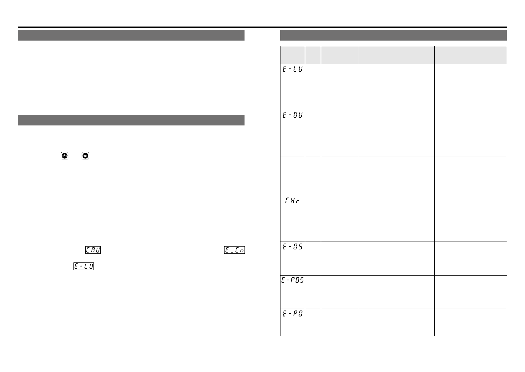
List of protective functions
Display on
the Digital
key pad
LED
ashes
When any of protective functions marked with “ * ” operates, trip reset by the procedure of [1] on P.32.
Trip
number
(RS485)
Protective
function
2 Undervoltage
error
(E-LV)
3 Overvoltage
error
(E-OV)
— Overload
warning
(Electronic
thermal)
4 Overload error
(Electronic
thermal relay)
(THr)
5 Overspeed
error
(E-OS)
6 Position error
(E-POS)
7 * Position
error counter
overow
(E-PO)
Causes Countermeasure
The motor trips when internal
DC voltage (voltage of
smoothing capacitor of power
supply) is below specied
value.
Product of 100 V: Approx DC100 V
Product of 200 V: Approx DC200 V
The motor trips when internal
DC voltage (voltage of
smoothing function of power
supply) rises and
exceeds specied value.
Product of 100 V: Approx DC200 V
Product of 200 V: Approx DC400 V
When load factor exceeds
specied value, the electronic
thermal relay operates and
monitor display ashes. It is an
alarm fo
50 to 130 W: 100
The motor trips when motor
torque is output continuously
above specied value.
50 to 130 W: 115
The motor trips when rotation
speed (actual speed) exceeds
specied value.
Approx 6000 r/min
The motor trips when position error (difference between
command position and actual
position) is greater than Pr39 ×
8 [pulses].
The motor trips when the position error exceeds 8388607
[pulse].
%
%
Investigate the condition of
wiring and power supply.
It is possible that deceleration
time is too short. Set longer
deceleration time.
Not compatible with continuous lowering operation.
Reduce the load.
Check the load factor in monitor mode.
Investigate the cause of overload, and reduce the load,
change the operating pattern
by making acceleration and
deceleration time longer, or
apply design to increase the
capacity of motor.
Ensure that the actual speed
does not exceed rated rotation
speed, such as overshooting
by unmatching between load
and gain.
Check the parameter again
and adjust gain.
Check the parameter again
and adjust gain.
-33--32-
 Loading...