

Panasonic MINAS A5, MINAS A5E, MINAS A6SG, MINAS A6SF Quick Start Manual
Servo Drives
Quick Start Guide
Position control by pulse
and direction signals
(MINAS A5/A5E/A6SG/A6SF)
QS2000_V1.1_EN
2019.07
www.panasonic-electric-works.com

Liability and copyright
Liability and copyright
This manual and everything described in it are copyrighted. You may not copy this manual, in
whole or part, without written consent of Panasonic Electric Works Europe AG (PEWEU).
PEWEU pursues a policy of continuous improvement of the design and performance of its
products. Therefore we reserve the right to change the manual/product without notice. In no
event will PEWEU be liable for direct, special, incidental, or consequential damage resulting
from any defect in the product or its documentation, even if advised of the possibility of such
damages.
Please direct support matters and technical questions to your local Panasonic
representative.
2 QS2000_V1.1_EN

Table of contents
Table of contents
1 Introduction................................................................................................................................. 4
1.1 Before you start................................................................................................................................ 4
1.2 About this document......................................................................................................................... 4
1.3 Related documents...........................................................................................................................4
1.4 Available software.............................................................................................................................5
2 Functional overview................................................................................................................... 6
3 Wiring...........................................................................................................................................7
3.1 Recommendations for wiring............................................................................................................ 7
3.2 Connectors of the servo driver.........................................................................................................7
3.3 Signal inputs and outputs of the X4 connector................................................................................ 9
3.4 PNP wiring of the X4 connector.....................................................................................................10
3.5 NPN wiring of the X4 connector.....................................................................................................11
4 Make parameter settings in PANATERM................................................................................12
4.1 Basic parameters overview.............................................................................................................12
4.2 Pr0.00 (Motor rotation direction).....................................................................................................13
4.3 Pr0.01 (Control mode).................................................................................................................... 13
4.4 Pr0.06 (Counting direction of the command pulses)...................................................................... 13
4.5 Pr0.07 (Input mode of the command pulses).................................................................................14
4.6 Pr0.08 (Number of pulse signals per motor revolution)................................................................. 15
4.7 Pr0.09 (Gear ratio numerator) and Pr0.10 (Gear ratio denominator).............................................15
4.8 Pr5.32 (Maximum pulse input frequency).......................................................................................15
5 Make pin assignments in PANATERM....................................................................................16
6 Help us improve....................................................................................................................... 17
7 Record of changes...................................................................................................................18
QS2000_V1.1_EN 3

1 Introduction
1 Introduction
1.1 Before you start
Before operating this product, read the safety instructions in the related Operating
Instructions.
This product is for industrial use only.
Electrical connections must be made by qualified electrical personnel.
1.2 About this document
This Quick Start Guide is intended to help you set up a MINAS servo drive system. It is
based on information from the MINAS series manuals and the practical experience of our
engineers.
Step-by-step instructions will guide you through connecting a PLC to a MINAS servo driver
and setting the most important parameters in the PC configuration software PANATERM.
1.3 Related documents
Please refer to the original servo drive manuals for detailed information. Click on the
following links to download the documents from our Panasonic Download Center.
• Information on wiring, position control, and parameters:
Operating Instructions (Overall) AC Servo Motors & Driver MINAS A5 series
Operating Instructions (Overall) AC Servo Motors & Driver MINAS A6 series
• Information on using the PANATERM configuration software:
Operation Manual: Set up support software PANATERM Ver. 6.0
• Information on how to reduce electromagnetic interference (EMI):
Recommendations for EMC-compliant wiring of servo drivers and motors
• Other Quick Start Guides:
QS2001, Position control by block operation using input signals (MINAS A6SG/A6SF)
QS2002, Position control by block operation using Modbus commands (MINAS A6)
QS2003, Position control in EtherCAT networks MINAS A5B/A6B
QS2004, Position control using RTEX (MINAS A5N/A6N)
QS3000, Velocity control (MINAS A5/A6F)
QS4000, Torque control (MINAS A5/A6)
4 QS2000_V1.1_EN

QS5000, PANATERM - Trial run
QS5001, PANATERM - Auto-tuning
QS5002, PANATERM - Fit gain tuning
1.4 Available software
The following software is available free of charge in our Panasonic Download Center. Click
on the link to start the download.
• PC configuration software PANATERM
• PC programming software Control FPWIN Pro 7
1.4 Available software
QS2000_V1.1_EN 5
2 Functional overview
2 Functional overview
Position control is a control mode in which the motor moves the load to a specified target
position.
The servo driver can be controlled by a pulse train in the frequency range between 1Hz and
8MHz from a host controller such as a PLC or a CNC controller or by block operation. This
Quick Start Guide explains how to wire and configure the servo driver to receive pulses from
a PLC.
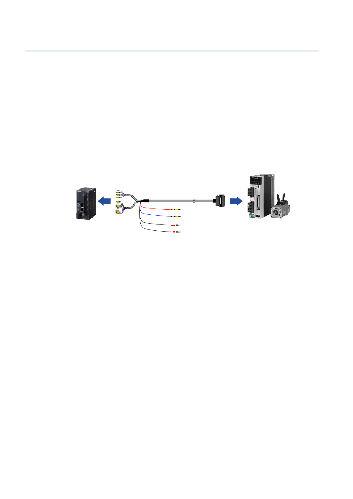
Example
An FP0H PLC and a MINAS A6SF servo driver are connected to control the driver by I/O
signals. If needed, additional signals, such as servo-ready, alarm, or positioning complete,
can also be transmitted.
Servo Axis
+
-
+24V DC
0V DC
CWL
CCWL
(1)
Connect to external power supply.
(2)
Connect to limit switches.
(1)
(2)
Data transmission between PLC and servo driver via connection cable
6 QS2000_V1.1_EN
 Loading...