

Page 1
[Connections and Settings
in Torque Control Mode]
page
Torque control block diagram..............................132
CN X5 Connector...................................................133
CN X5 Connector ...................................................................... 133
Interface Circuit ......................................................................... 134
Input signal (common) assignment to CN X5 connector pins... 136
Input signal assignment to CN X5 connector pins - designation(logic)
Output signal assignment to CN X5 connector pins - designation(logic)
Trial run at Torque Control Mode.........................140
Operation with CN X5 Connected ............................................. 140
Real time auto gain tuning ...................................142
Outline ....................................................................................... 142
Application range....................................................................... 142
How to use ................................................................................ 142
Parameters, which are set up automatically ............................. 143
Caution ...................................................................................... 143
Parameter Setting .................................................144
Parameters for Function Selection............................................ 144
Parameters for Time Constants of Gains and Filters: Related to Real Time Auto Tuning .....
Parameters for real time auto gain tuning................................. 148
Parameters for Switching to 2nd Gains..................................... 150
Parameters for Position Control ................................................ 150
Parameters for Speed Control .................................................. 151
Parameters for Torque Control.................................................. 152
Parameters for various sequences ........................................... 152
.......... 138
....... 138
147
Page 2
Pr 11
Pr 1
2
Pr 1
3
Pr 14
Pr 1
9
Pr 1
A
Pr 1
B
Pr 1
C
Pr 1
D
Pr 1
E
Pr 2
0
Pr 2
8
Pr 2
9
Pr 2
A
Pr 5
C
Pr 5
D
Pr 5
2
Pr 4
4
Pr 4
5
Inverse
Offset
Gain
Inverse
Gain
1st ratio
1st
differential
2nd
differential
2nd ratio
Inertia
ratio
1st
frequency
1st width
2nd
frequency
2nd
width
2nd
depth
1st time
constant
2nd time
constant
2nd
1st
Inverse
Division
Limit
Pr 5
E
Pr 2
7
Pr 5
6
16bitA/
D
Pr 5
C
Pr 5
D
10bitA/
D
Sign( )
Analog torque
command
Analog torque
command
SPR /
TRQR
When pr 02 = 2 or 4
Input setting
Input setting
When pr 02 = 5
Absolute
(magnitude)
Command speed
monitor
Multiplication
Internal speed limit
4th
speed
Speed control
Notch filter Torque f ilter
Torque
limit
Disturbance
observer
Filter
Actual speed
monitor
Speed
detection filter
Speed detection
Encored
receive
processing
PS / PS signal
Division
Feedback pulse
OA / OB / OZ
Torque command
monitor
Encoder
Motor
CCWTL /
TRQR
+
–
+
–
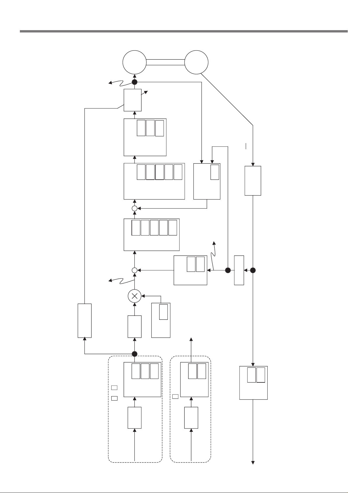
±
Torque contr ol block diagram
132
Page 3
Connections and Settings in
Torque Control Mode
Battery for absolute encoder
7
4.7k
Ω
COM+
PULS2
SIGN1
SIGN2
GND
OA+
OA
OB+
OB
OZ+
OZ
GND
CZ
SPR/TRQR
GND
CCWTL/TRQR
GND
CWTL
SP
IM
1
2
3
4
5
6
13
21
22
48
24
46
47
25
19
20
14
15
16
17
43
18
42
49
23
10k
Ω
10k
Ω
20k
Ω
220
Ω
220
Ω
10k
Ω
10k
Ω
1k
Ω
1k
Ω
PULS1
INH
CL
SRV-ON
GAIN
DIV
ZEROSPD
C-MODE
A-CLR
CCWL
CWL
S-RDY+
S-RDY
-
ALM+
COIN+
BRKOFF
+
BRKOFF
TLC
V
DC
12
-
24V
ZSP
COM
BATT+
to CN X4 (5th pin)
to CN X4 (6th pin)
BATT
-
CN X5
FG
COIN
-
ALM
-
33
30
29
27
28
26
32
31
9
8
35
34
37
36
39
38
11
10
40
12
41
44
45
50
Servo-ON
P-operation/2nd gain
switching
Control mode switching
Scaler
Alarm clear
CCW overtravel inhibit
A-phase
output
B-phase
output
Z
Z-phase
output
Speed monitor
Torque monitor
Z-phase output (Open collector)
CW overtravel inhibit
Servo ready
Servo alarm
At-speed
Mechanical brake release
· In case the battery for absolute encoder
is installed at the controller side
Torque limited
(Pr09)
Zero speed detected
(Pr0A)
<Note> Specify the speed limit value using
4th speed set-up (Pr56) parameter.
SPR/TRQR
GND
CCWTL/TRQR
GND
14
15
16
17
330
Ω
330
Ω
330
Ω
Zero speed clamp (Pr06)
Torque command
(0 to ±10V)
Wiring when Pr02
(Control Mode) = 5
Speed
command
(0 to ±10V)
Torque
command
(0 to ±10V)
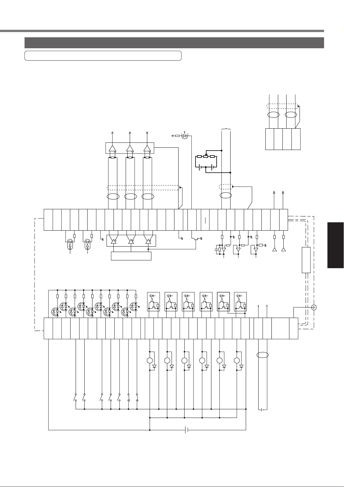
CN X5 Connector
[Connections and Settings in Torque Control Mode]
CN X5 Connector
Circuits Available for Torque control mode
133
Page 4
+
CN X5 Connector
1
1
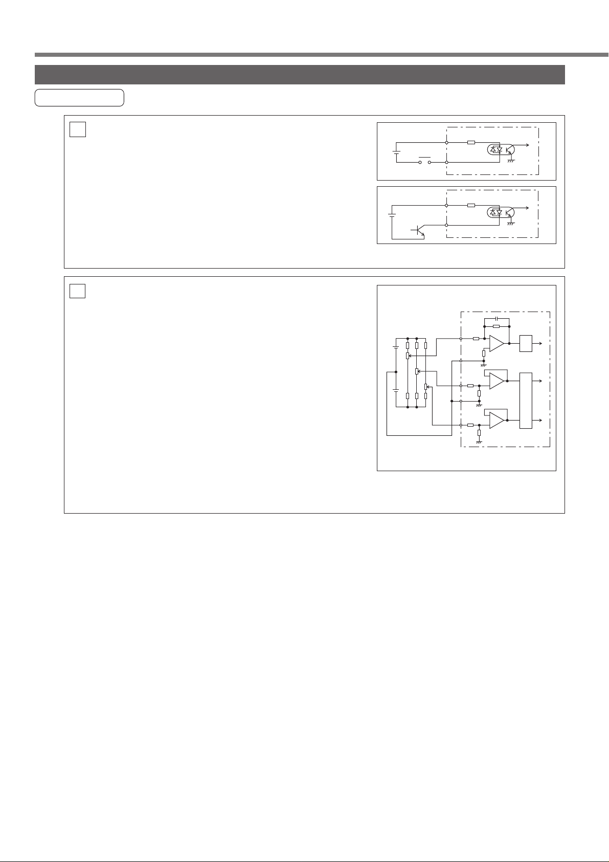
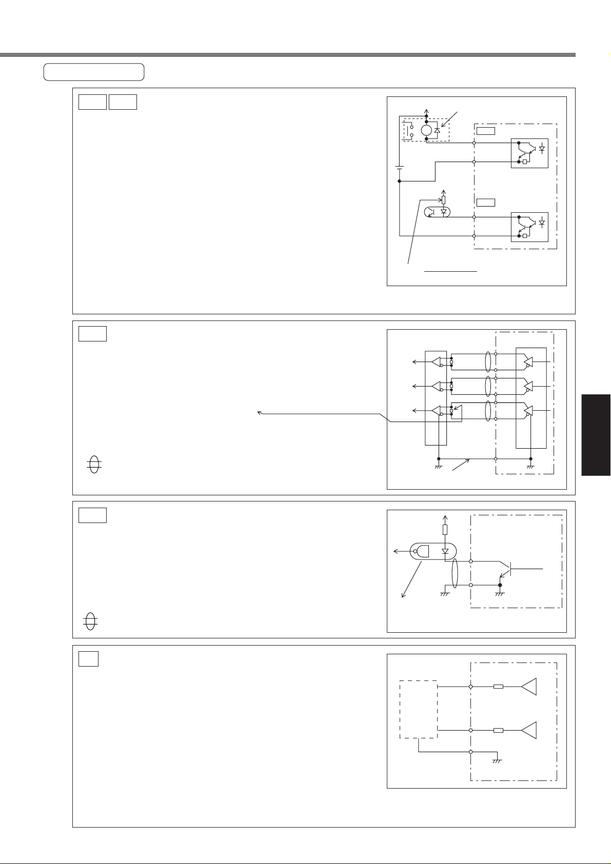
Interface Circuit
Input Circuit
SI Connecting to
SI
sequence input signals
• Connect to a contact of switch and relay, or a transistor
of an open collector output.
• Use a s witch or relay for micro current so that insufficient
contact can be avoided.
• Lower limit of the power supply (12 to 24V) should not be
less than 11.4V in order to secure the appropriate level
of primary current of the photo coupler.
AI
AI Analogue Command Input
• There are three analogue command inputs of SPR/RTQR
(14 pins), CCWTL (16 pins) and CWTL (18 pins).
• The maximum permissible input voltage is ±10V. F or the
input impedance of these inputs, see the right figure.
• If you make a simplified circuit comprising a variable resistor (VR) and resistor (R), refer to the right figure.
When the variable range of each input is -10V to +10V,
the VR should be a B type resistor of 2kΩ (min.1/2W).
The R should be 200Ω (min.1/2W).
• The A/D converters for these inputs should have the following resolution.
12V
2–24V
2–24V
R
VR
-12V
R
Relay
SPR/TRQR
CWTL
7
COM+4.7kΩ
Servo-ON or
other input
7 COM+4.7kΩ
Servo-ON or
other input
20kΩ
14
GND
15
10kΩ
16
CCWTL
GND
17
10kΩ
18
10kΩ
10kΩ
-
ADC
ADC
1
2
+
+
+
1) ADC1 (SPR and TRQR) : 16 bits (including one bit for sign)
2) ADC2 (CCWTL and CWTL) : 10 bits (including one bit for sign)
134
Page 5
[Connections and Settings in Torque Control Mode]
Connections and Settings in
Torque Control Mode
A
R
H
p
(
Output Circuit
Sequence output circuit
SO1 SO2
• This comprises a Darlington driver with an open collector.
This is connected to a relay or photo coupler.
• There exists a collector-to-emitter voltage V
approx. 1V at transistor ON, because of Darlington con-
CE(SAT) of
12–24V
nection of the out put transistor. Note that normal TTLIC
can't be directly connected since this does not meet VIL
requirement.
• This circuit has an independent emitter connection, or an
emitter connection that is commonly used as the minus
(–) terminal (COM–) of the control power.
• Calculate the value of R using the formula below so as the
primary current of the photo coupler become approx. 10mA.
[kΩ] =
VDC[V] — 2.5[V]
For the recommended primary current value, check the data sheet on the equipment and photocoupler used.
Install as per the fig. Shows
without fail
SO1
ALM+
or other signal
ALM–
or other signal
V
DC
SO2
ZSP, TLC
COM–41
Maximum rating: 30V, 50m
10
PO1
Line Driver (Differential Output) Output
• Provides differential outputs of encoder signals (A, B and
Z phases) that come from the scalar.
• Receive these signals with a line receivers. In this case,
install a resistor of approx. 330Ω between the inputs.
• These outputs are non-insulated signals.
shows a pair of twisted wires.
Open Collector Output
PO2
• Outputs Z-phase signals among those from the encoder.
The outputs are non-insulated.
• Receive these signal with high-speed photo coupler at
controller side, since these Z-phase signal width is normally narrow.
shows a pair of twisted wires.
AM26LS32
or equivalent
OA+
OA-
OB+
OB-
OZ+
OZ-
Connect the signal
grounds between the controller and driver.
1925CZ
igh-speed
hoto coupler
Equivalent to T oshiba TLP554)
AM26LS31
or equivalent
21
22
48
49
23
24
25GND
Maximum rating:
30V, 50mA
GND
A
B
Z
Analogue Monitor Output
AO
• This output is the speed monitor signal (SP) or torque moni-
• The signal range is approx. 0 to ± 9V.
• The output impedance is 1kΩ. Pay attention to the input
<Resolution>
1) Speed monitor signal (SP): 8r/min./LSB calculated from
2) Torque monitor signal (IM): 0.4%/LSB calculated from 3V/rated value (100%)
tor signal (IM).
impedance of your measuring instruments and external
circuits connected.
6V/3000r/min (Pr07 = 3)
Measuring
instrument
or external
circuit
43
42
17
SP
IM
GND
1kΩ
1kΩ
135
Page 6
CN X5 Connector
it
4
4
4
4
4
Input signal (common) assignment to CN X5 connector pins
Input Signals (Common) and their Functions
Signal Pin No. Symbol Function I/F circu
Control signal
power (+)
Control signal
power (–)
Servo-ON
Control mode
switching
7
41
29
<Notes>
This signal becomes effective about two seconds after power on (see the Timing Chart).
1.
2. Don't use this Servo-ON or Servo-OFF signal to turn on or off the motor. See page
46 "Dynamic Brake" in Preparations.
• Allow at least 50ms delay after the driver is enabled before any command input is
entered.
• By opening the connection to COM– , the driver will be disabled(Servo-OFF) and
the current flow to the motor will be inhibited.
• Operation of the dynamic brake and clearing action of the position error counter can
be selected using Pr69 (Sequence under Servo-OFF).
32
Pr02 value
COM +
COM –
SRV-ON
C-MODE
3
4
5
• Connect to (+) of an external power supply (12VDC to
24VDC).
• Use source voltage of 12V±10% – 24V±10%.
• Connect to (–) of an external power supply (12VDC to
24VDC).
• The required capacity depends on the I/O circuit
configuration. 0.5A or larger is recommended.
• When this signal is connected to COM-, the dynamic brake
will be released and the driver is enabled. (Servo-ON).
• When Pr02 (Control Mode Selection) = 3, 4 or 5, the control
mode is selected per the table below.
Connection with COM–
open (1st)
Position control mode
Position control mode
Speed control mode
closed (2nd)
Speed control mode
Torque control mode
Torque control mode
–
SI
page 13
SI
page 13
CW overtravel
inhibit
CCW overtravel
inhibit
Counter clear
8
9
30
Position control
Speed control
Torque control
CWL
CCWL
CL
• If COM– is opened when the movable part of the machine
has moved to CW exceeding the limit, the motor does not
generate torque.
• If COM– is opened when the movable part of the machine
has moved CCW exceeding the limit, the motor does not
generate torque.
•
If you set 1 to Pr04 (Overtravel input inhibited invalid), CWL/CCWL
input will be disabled. A factory setting is Disable (1).
• With Pr66 (DB deactivate when driving is inhibited), you can
activate dynamic brake when CWL/CCWL input is enabled.
According to a factory setting, dynamic brake operates
(Pr66 is set to 0).
The function differs depending on the control mode.
• Clears the position error counter.
Connect to COM– to clear the counter.
• Use Pr4D to select the clear mode.
Pr4D value
0(Factory-setting)
1
• With speed setting of the 2nd selection input, you can set 4
speeds in combination with INH.
• For details, see Pr05 (Speed Set-Up Switching) description.
• Invalid
Meaning
LEVEL
EDGE
SI
page 13
SI
page 13
SI
page 13
136
Page 7
Connections and Settings in
Torque Control Mode
Signal Pin No. Symbol Function I/F circu
it
4
4
4
4
Command pulse
input inhibit
33
Position control
INH
[Connections and Settings in Torque Control Mode]
The function differs depending on the control mode.
• Enter command pulse input inhibit.
• You can disable this input with Pr43
(disable command pulse input inhibit).
Pr43 value
1(Factory-setting)
0
The INH signal (input) is disabled.
• With COM– closed, the pulse
command signal (PULSE SIGN) is
enabled.
• With COM– open, the pulse
command signal (PULSE SIGN) is
inhibited.
Meaning
SI
page 13
Speed zero clamp
Gain switching
Alarm clear
Speed control
Torque control
26
27
(Factory-setting)
31
ZEROSPD
GAIN
Pr30 value
0
1
A-CLR
• With speed setting of the 1st selection input, you can set 4
speeds in combination with CL input.
• For details, see Pr05 (Speed Set-Up Switching) description.
• Invalid
• With COM– open, the speed command is considered zero.
• This input can be made disabled using Pr06.
• With factory setting, disconnecting this pin from COM– sets
the speed to zero.
Pr06 value
0 (Factory-setting)
1
• This is setting of Pr30 (2nd gain setting) and has the
following 2 types of functions:
Connection
to COM-
Open
Close
Open
Close
To use the second gain, set Pr31 to “2”.
No.2 Gain change Funcutions, see page 202 "Adjustments ".
•
• If the COM- connection is kept closed for more than 120
ms, the alarm status will be cleared.
• For details about not cleared alarm, see page 216
"Protective Functions".
Speed loop: PI (Proportional / Integral) action
Speed loop: P (Proportional) action
• 1st gain selected (Pr10, 11, 12, 13 and 14)
• 2nd gain selected (Pr18, 19, 1A, 1B, 1C)
ZEROSPD is disabled.
ZEROSPD is enabled.
Meaning
Function
SI
page 13
SI
page 13
SI
page 13
137
Page 8

CN X5 Connector
it
4
4
it
5
5
5
Input signal assignment to CN X5 connector pins - designation(logic)
Input Signals (Speed Control) and their Functions
Signal Pin No. Symbol Function I/F circu
Speed (torque)
command
CCW torque limit
CW torque limit
Battery +
Battery -
14
(15)
16
(17)
18
(17)
44
45
SPR/TRQR
(GND)
CCWTL/
TRQR*
(GND)
CWTL
(GND)
BATT +
BATT -
* When the torque control mode is selected at the speed/torque switching mode (Pr02 = 5), the
No.16 pin (CCWTL/TRQR) becomes the torque command input (analogue). You can set-up the
relationship between the command voltage level and the motor torque with Pr5C (Torque Command Input Gain).
< At speed control >
• This becomes speed command input (analogue) 0–±10V
• You can set-up the relationship between the command
voltage level and the motor speed, with Pr50 (Speed
Command Input Gain) .
• Use Pr51 to inverse the polarity of the command input.
< At torque control >*
• This becomes torque command input (analogue) 0–±10V
• You can set-up the relationship between the command
voltage level and the motor torque, with Pr5C (Torque
Command Input Gain) .
• Use Pr5D to inverse the polarity of input signals.
• Use Pr56 (4th Speed Set-up) to adjust the speed limit in
torque control.
< Note >
SPR/TRQR are invalid in position control mode.
< At speed and position control >
• You can limit the motor torque in the CCW direction by
entering positive voltage (0 to +10V) to CCWTL.
• You can limit the motor torque in the CW direction by
entering negative voltage (-10 to 0V) to CWTL.
• The torque limit value is proportional to the voltage with a
factor of 100%/3V.
• CCWTL and CWTL are valid when Pr03 (Torque Limit Input
Inhibit) = 0. They are invalid when Pr03 = 1.
< At torque control >*
• Both of CCWTL and CWTL are invalid.
• Use the 4th speed set-up(Pr56) to limit the speed.
• Connect a backup battery for absolute encoder (polesensitive !).
• If the battery is connected directly to the driver, it is not
necessary to connect a battery to this terminal.
AI
page 13
AI
page 13
–
Output signal assignment to CN X5 connector pins - designation(logic)
Output Signals (Common) and their Functions
Signal Pin No. Symbol Function I/F circu
• This output(transistor) turns OFF, when the driver detects
and error(trip).
• This output(transistor) turns ON, when the main power is
on(for both the driver and the motor) and no alarm is active.
•
This is used to release the electromagnetic brake of the motor.
• Turn the output transistor ON when releasing brake.
• Refer to “Timing Chart” on page 40, on Preparations.
• This output(transistor) turns ON , when the brake is re-
leased.
• See page 40 "Timing Chart".
138
Servo alarm output
Servo-ready output
Mechanical brake
release output
37
36
35
34
11
10
ALM +
ALM –
S-RDY +
S-RDY BRK-OFF +
BRK-OFF –
SO1
page 13
SO1
page 13
SO1
page 13
Page 9

[Connections and Settings in Torque Control Mode]
Connections and Settings in
Torque Control Mode
it
5
5
5
5
5
5
5
it
Signal Pin No. Symbol Function I/F circu
Zero speed
detection
Torque in-limit
In-position/
At-speed
12
Pr0A value
(Factory-setting)
* When the setting is a value between 2 and 5, the output transistor will be turned on
for at least 1 second upon detecting an alarm condition.
40
39
38
Position
Speed and
torque
ZSP
0
1
2*
3*
4*
5*
TLC
COIN +
COIN –
• Signal which is selected at Pr0A (ZSP Output Selection) will
be turned on.
Function
Output(transistor) turns ON during the In-toque limiting.
Output(transistor) turns ON when the motor speed becomes
lower than that of the preset speed with Pr61(Zero speed).
Output(transistor) turns ON when either one of overregeneration, overload or battery warning is activated.
Output(transistor) turns ON when the over-regeneration (more
than 85% of permissible power of the internal regenerative
discharge resistor) warning is activated.
Output(transistor) turns ON when the overload (the effective torque is
more than 85% of the overload trip level) warning is activated.
Output(transistor) turns ON when the battery (the voltage of the
backup battery becomes lower than approx. 3.2V at the
encoder side) warning is activated.
• Signal which is selected by Pr09 (TLC Output Selection) will
be turned ON. Factory-setting: 0
See the above ZSP signal for the set-up of Pr09 and functions.
•
• Function changes at control mode.
• In-position output
• Output(transistor) turns ON when the position error is below
the preset value by Pr60 (In-Position Range).
• At-speed output
• Output(transistor) turns ON when the motor speed reaches
the preset value by Pr62 (At-Speed ).
SO2
page 13
SO2
page 13
SO1
page 13
A-phase output
B-phase output
Z-phase output
Z-phase output
Speed monitor
output
Torque monitor
output
21
22
48
49
23
24
19
43
(17)
42
(17)
OA +
OA –
OB +
OB –
OZ +
OZ –
CZ
SP
(GND)
IM
(GND)
• Provides differential outputs of the encoder signals (A, B
and Z phases) that come from the driver (equivalent to
RS422 signals).
• The logical relation between A and B phases can be
selected by Pr45 (Output Pulse Logic Inversion).
• Not insulated
• Z-phase signal output in an open collector (not insulated)
• Not insulated
• Outputs the motor speed, or voltage in proportion to the
commanded speed with polarity.
+ : CCW rotation
– : CW rotation
• Use Pr07 (Speed Monitor Selection) to switch between
actual and commanded speed, and to define the relation
between speed and output voltage.
• Outputs the output torque, or voltage in proportion to the
position error with polarity.
+ : Fgenerating CCW-torque
– : Fgenerating CW-torque
• Use Pr08 (Torque Monitor Selection) to switch between
torque and positional error, and to define the relation
between torque/positional error and output voltage.
Output Signals (Others) and their Functions
PO1
page 13
PO2
page 13
AO
page 13
AO
page 13
Signal ground
Frame ground
(Not in use)
Signal Pin No. Symbol Function I/F circu
13, 15
17, 25
50
1, 2, 20
46, 47
GND
FG
–
• Signal ground in the driver
• Internally isolated from the control power (COM -).
• Internally connected to the earth terminal.
• No connections should be made.
–
–
–
139
Page 10

Trial run at Torque Control Mode
D
1
h
n
d
•
Operation with CN X5 Connected
1) Connect CN X5.
2) Connect the control signal (COM+/COM–) to the power supply (12 to 24 VDC) .
3) Turn the main power (driver) ON.
4) Check the defaults of the parameters.
5) Connect between SR V-ON (CN X5 pin 29) and COM- (CN X5 pin 41) to make Servo-On active. The motor
will be kept excited.
6) Apply an appropriate DC voltage between Torque command input TRQR (CN X5 pin 14) and GND (CN X5
pin 15) and verify the motor rotating direction (CW/CCW) and then reverse the voltage polarity and then
verify reversed motor rotation. Also check the speed set by Pr56.
7) To change torque Pr5C, direction Pr5D and speed limit Pr56 in response to the command voltage,
modify the following parameter.
Pr56: 4th speed
Pr5C: torque command input gain
Pr5D: torque command input inversion
See page 144 "Parameter setting" in Torgue control mode.
Wiring Diagram Parameters
7
COM+
29
C
2V–24V
DC
10V
SRV-ON
26
ZEROSPD
41
COM–
14
SPR/TRQR
15
GND
ZEROSPD switc
Close: Run
Open: Stop
One way
operation
For multi directio
(CW and CCW)
operation, use a
bipolar power
source.
PrNo.
Pr02
Control mode set-up
Pr04
Overtravel input inhibit
Pr06
ZEROSPD input selection
Pr56
4th internal speed
Pr5C
Torque command input gain
Pr5D
Torque command input inversion
Use the controller to send command pulses.
Input Signals Status
No. Input signal
Servo-ON
0
CW overtravel inhibit
2
CCW overtravel inhibit
3
Speed zero clamp
5
ValueParameter description
2
1
0
Set as
require
Monitor
display
+ A
–
–
–
140
Page 11

[Connections and Settings in Torque Control Mode]
Connections and Settings in
Torque Control Mode
MEMO
141
Page 12

Real time auto gain tuning
r
Outline
Load inertia of the machine is estimated
at real time, and the optimum gain is set
up automatically based on the estimated
result. A load, which has a resonance, also
can be handled owing to the adaptive filter.
Position/speed
command
Operation command under
actual operation conditions
Gain auto
setting
Position/speed
control
Filter auto
tuning
Applied
filter
Resonant frequency estimate
Load inertia estimate
Real time auto
gain tuning
Servo driver
Torque
command
Current
control
Motor
current
Motor
speed
Motor
Encoder
Application range
Under the following conditions, the real time auto gain tuning may not function properly.
In such case, use the normal mode auto gain tuning (see page 193 "Adjustments") or manual gain tuning
(see page 197 "Adjustments").
Conditions under which the real time auto gain tuning is prevented from functioning
• When the load inertia is smaller/larger than the rotor inertia
Load inertia
Load
Operation pattern
(3 times or less; or 20 times or more)
• When the load inertia fluctuates
• When the machine stiffness is extremely low
• When any unsecured part resides in such as backlash, etc.
• In case of a continuous low speed operation under 100 [r/min].
• In case of soft acceleration/deceleration under 2000 [r/min] per 1 [s].
•
When acceleration/deceleration torque is smaller than unbalanced load/viscous friction torque.
How to use
[1] Stop the motor (Servo-OFF).
[2] Set up Pr21 (Real-time auto tuning set-up) to 1 – 6.
Set up value before shipment is1.
Setting value
0
Real-time auto tuning
Not used
[1]
2
3
Used
4
5
6
7
Not used
When the changing degree of the load inertia is too large, set Pr21 to 3 or 6.
When the influence of resonance is conceivable, select “adaptive filter YES”.
[3] Set 0 – 2 to Pr22 (real-time auto tuning machine stiffness).
[4] Tur n the servo ON to operate the machine ordinarily.
[5] To increase the response performance, gradually increase Pr22 (Machine stiffness at real-time
auto tuning). When any noise or vibration is found, decrease the Pr22 to a lower value soon.
Changing degree of load inertia during operation
–
Adaptive filte
No
Little change
Change slowly
Yes
Change s haply
Little change
Change slowly
No
Change s haply
–
Yes
[6] To store the result, wr ite the data into the EEPROM.
142
Page 13

[Connections and Settings in Torque Control Mode]
Connections and Settings in
Torque Control Mode
e
Parameters, which are set up automatically
The following parameters
are tuned automatically.
Parameter No.
11
12
13
14
19
1A
1B
1C
20
Name
1st speed loop gain
1st
speed loop integration time constant
1st speed detection filter
1st torque filter time constant
2nd speed loop gain
2nd
speed loop integration time constant
2nd speed detection filter
2nd torque filter time constant
Inertia ratio
Parameter No.
The following parameters are also set up
to the following fixed values automatically.
Name Set valu
27
30
3A
Disturbance torque observer filter selection
2nd gain action set-up
Torque control switching mode
0
1
0
Caution
[1] Immediately after the first servo ON at startup or when Pr22 (machine stiffness at real-time auto tuning)
is increased, abnormal noise or oscillation may be generated before load inertia is determined. This is
not anomaly if it is stabilized shortly. However when such problems as oscillation or noise that continues
for 3 reciprocal operations or longer is encountered frequently, take the following measures:
1) Write the parameter of normal operation into the EEPROM.
2) Decrease the Pr22 (Machine stiffness at real-time auto tuning).
3) Once set up Pr21 (Real-time auto tuning set-up) to 0 to disable the adaptive filter. Then, enable the
real time auto tuning again. (resetting of inertia estimate adaptive operation)
[2] After abnormal noise or oscillation, Pr20 (inertial ratio) may be changed to an extreme value. In such a
case, also take the above measures.
[3] Among results of real-time auto gain tuning, Pr20 (inertia ratio) is programmed into EEPROM every 30 min-
utes. When you turn on the power again, auto tuning will be executed using the data as initial value.
143
Page 14

Parameter Setting
]
Parameters for Function Selection
Parameter
No.
00 0 – 15
Parameter Name Function/Description
Axis address In communications with a host device such as a personal computer that uses
• At power on, settings of the rotary switch ID on the front panel (0 – F) will be
programmed into parameters of the driver.
• Settings of Pr00 can be changed only by means of the rotary switch ID.
Setting
range
[1]
RS232C/485 with multiple axes, you should identify to which axis the host accesses
and use this parameter to confirm axis address in terms of numerals.
Default setting is shown by [
01 0 – 15LED display at
power up
Power ON
Setting of Pr01
See page 56 "Front Panel Key Operations and Display".
02 0 – 14Control mode Select the control mode of the servo driver.
In the initial condition after turning ON the control power, the following data displayed
on the 7-segment LED can be selected.
Setting
value
0
Positional deviation
[1]
Flashing during initialization
(about 2 seconds)
10
11
12
13
14
15
Motor revolving speed
2
Torque output
3
Control mode
4
I/O signal status
5
Error cause/record
6
Software version
7
Alarm
8
Regenerative load ratio
9
Overload load ratio
Inertia ratio
Feedback pulse sum
Command pulse sum
External scale deviation
External scale feedback pulse sum
Motor auto recognition
Description
144
Setting
value
0
[1]
2
3
4
5
6
7
8
9
10
11
12
13
14
Control mode
The 1st Mode The 2nd Mode*1
Position control
Speed control
Torque control
Position
Position
Speed
Semi-closed control
Full-closed control
Hybrid control
Speed
Speed
High-stiff equipment
position control
Low-stiff equipment
position control
Low-stiff equipment
speed control
Second full-closed control
–
–
–
Speed control
Torque control
Torque control
–
–
–
External encoder control
Semi-closed control
–
–
–
–
*1 A special control mode focused on the full-closed
specification. For details, refer to “Full-Closed
Control” volume on Page 000.
*2 When composite mode (Pr02 = 3,4,5,9,10) is set,
you can switch the 1st and 2nd modes with the
control mode switch input (C-MODE).
C-MODE
<Caution>
Enter a command after 10ms or longer have passed
since C-MODE was entered.
Do not enter any command on position, speed or
torque.
Open
The 1st The 2nd
10 ms or longer 10 ms or longer
Closed
Open
The 1st
Page 15

Connections and Settings in
Torque Control Mode
-
l
r
Parameter
]
,
No.
Parameter Name Function/Description
04 0 – 1Overtravel input
inhibit
Setting
range
[Connections and Settings in Torque Control Mode]
Default setting is shown by [
In the case of linear driving, in particular, to prevent mechanical damage due to
overtraveling of work, you should provide limit switches on both ends of the axis, as
shown below, whereby driving in a direction of switch action is required to be
inhibited.
CW direction CCW direction
Work
Setting
value
0
[1]
06 0 – 1ZEROSPD input
selection
CCWL/CWL
Input
Enable
Disable
Servo Motor
Limit
Switch
Limit
Switch
Driver
CCWL
CWL
Input
CCWL
(CN X5-9 pin)
CWL
(CN X5-8 pin)
Connection with COM-
Connected
Open
Connected
Open
Normal condition in which the limit switch on
CCW side is not operating.
CCW direction inhibited, CW direction allowed
Normal condition in which the limit switch on
CW side is not operating.
CW direction inhibited, CCW direction allowed
Action
Both CCWL and CWL inputs are ignored and they normally operate as no
overtravel inhibit being set.
<Cautions>
1. When you set 0 to Pr04 and do not connect both CCWL and CWL inputs to COM
(off), abnormal condition in which limits are exceeded in both CCW and CW
directions is detected, and the driver will then trip due to “abnormal overtrave
input inhibit“.
2. You can set whether or not to activate the dynamic brake when slowdown occurs
because CCW or CW overtravel input inhibit has been enabled. For details, refe
to descriptions on Pr66 (DB deactivation at overtravel input inhibit).
This sets switching of enable and disable of speed zero clamp input (ZEROSPD
CNX5 26-pin).
Setting value
[0]
1
Function of ZEROSPD Input (26-pin)
ZEROSPD input being ignored, it is determined that it is not speed
zero clamp state at all times.
ZEROSPD input has been enabled. If connection with COM- is
opened, speed command will be regarded as zero.
07 0 – 9Speed monitor
(SP) selection
The parameter selects/sets a relationship between voltage output to the speed
monitor signal output (SP: CN X5 43-pin) and the actual motor speed or command
speed.
Setting value
0
1
2
[3]
4
5
6
7
8
9
SP Signals
Motor Actual
Speed
Command
Speed
Relationship between Output Voltage Level and Speed
6V / 47 r/min
6V / 187 r/min
6V / 750 r/min
6V / 3000 r/min
1.5V / 3000 r/min
6V / 47 r/min
6V / 187 r/min
6V / 750 r/min
6V / 3000 r/min
1.5V / 3000 r/min
145
Page 16

Parameter Setting
r
]
Parameter
No.
08 0 – 12Torque monitor
Parameter Name Function/Description
(IM) selection
Setting
range
The parameter selects/sets a relationship between voltage output to the torque
monitor signal output (IM: CN X5 42-pin) and generated torque of the motor o
number of deviation pulses.
Default setting is shown by [
09 0 – 5TLC output
selection
0A 0 – 5ZSP output
selection
1
2
3
4
5
1
2
3
4
5
0
2
3
4
5
IM Signals
Torque
No. of
Deviation
Pulses
Torque
Output in torque limit
Output of zero-speed detection
Output of an alarm due to either of overregeneration/overload/absolute battery
Output of over-regeneration alarm
Output of overload alarm
Output of absolute battery alarm
Output in torque limit
Output of zero-speed detection
Output of an alarm due to either of overregeneration/overload/absolute battery
Output of over-regeneration alarm
Output of overload alarm
Output of absolute battery alarm
Relationship between output level and torque or number of deviation pulses
3V / rated (100%) torque
3V / 31Pulse
3V / 125Pulse
3V / 500Pulse
3V / 2000Pulse
3V / 8000Pulse
Enabled under full-closed control (See P156 –.)
3V / 200% torque
3V / 400% torque
Functions
Functions
Remarks
For functional details of respective
outputs listed left,
refer to "Wiring to
Connector CN X5"
on page 78.
Remarks
For functional details of respective
outputs listed left,
refer to "Wiring to
Connector CN X5"
on page 78.
Setting value
[0]
6 – 10
11
12
The parameter allocates functions of output in torque limits (TLC: CN X5 40-pin).
Setting value
[0]
The parameter allocates functions of zero speed detection output (ZSP: CN X5 12-pin).
Setting value
[1]
0B 0 – 2Absolute encoder
set up
0C 0 – 2Baud rate of
RS232C
0D 0 – 2Baud rate of
RS485
Listed below are settings when you use the absolute encoder:
Setting value
0
[1]
2
Setting value
0
1
[2]
Setting value
0
1
[2]
To use the absolute encoder as absolute.
To use the absolute encoder as incremental.
To use the absolute encode as absolute. In this case, multi-rotation
excess counter is ignored.
Description
Baud Rate
2400bps
4800bps
9600bps
Baud Rate
2400bps
4800bps
9600bps
146
Page 17

[Connections and Settings in Torque Control Mode]
Connections and Settings in
Torque Control Mode
r
]
Parameters for Time Constants of Gains and Filters: Related to Real Time Auto Tuning
Default setting is shown by [
Parameter
No.
11 1 – 3500
12 1 – 1000
13 0 – 6
14 0 – 2500
19
1A
1B
1C
1D
1E 0 – 4
Parameter Name Unit Function/Description
gain
integration time
constant
detection
filter
time constant
2nd Velocity loop
gain
2nd Velocity loop integration time constant
2nd speed
detection filter
2nd torque filter
time constant
frequency
selection
Setting
range
[35]*
[16]*
[0]*
[65]*
1 – 3500
[35]*
1 – 1000
[1000]*
0 – 6
[0]*
0 – 2500
[65]*
100 – 1500
[1500]
[2]
Hz1st Velocity loop
ms1st Velocity loop
–1st speed
0.01ms1st torque filter
Hz
ms
–
0.01ms
Hz1st notch
–1st notch width
• The parameter defines responsiveness of the speed loop. You need to
set this speed loop gain high so as to improve responsiveness of the
entire servo system by increasing position loop gain.
• This parameter is an integration element of a speed loop and acts to
drive quickly the subtle speed deviation into zero. The smaller the
setting is, the faster deviation will be zeroed.
• Setting of “1000” will remove effects of integration.
• The parameter sets in 6 phases (0 to 5) a time constant of the low-pass
filter inserted after the block of converting an encoder signal into a
speed signal.
•
Setting this parameter high would increase a time constant, thereby
reducing noise of the motor. However, usually use the factory setting (0).
• The parameter sets a time constant of the primary delay filter inserted
into the torque command unit.
• It effects the control of vibration because of the torsion resonance.
• A position loop, speed loop, speed detection filter, and torque command
filter, respectively, has 2 pairs of gains or time constants (the 1st and
2nd).
• Each function/content is similar to the 1st gain/time constraint, described
earlier.
• For details on switching of the 1st and 2nd gains or time constants, refe
to Adjustment volume on page 186.
* Pr11 and Pr19 will be set in terms of (Hz) when Pr20 inertia ratio has
been set correctly.
• The parameter sets frequency of the resonance suppression notch filter.
• You should set it about 10% lower than the resonance frequency of the
mechanical system that has been found by the frequency characteristics
analysis facility of the setup assisted software “PANATERMR®”.
• Setting this parameter ”1500” would disable the function of notch filter.
• The parameter sets width of the resonance suppression notch filter in 5
steps. The higher the setting is, the greater the width is.
• Normally, use a factory setting.
Note) Standard default setting in [ ] under "Setting range" and marked with * is automatically set during the
real time auto gain tuning. T o man ually change the value, first disable the auto gain tuning feature be
seeing page 196 "Disabling of auto tuning function" in Adjustments, and then enter the desired v alue .
147
Page 18

Parameter Setting
t
r
]
t
,
Parameters for real time auto gain tuning
Parameter
No.
20
21 0 – 7 –Real time auto
22 0 – 15
Parameter Name Unit Function/Description
Inertia ratio • Defines the ratio of load inertia to the motor's rotor inertia.
tuning set up
at auto tuning
Setting
range
0 – 10000
[100]*
Setting value
[4]
[1]
%
Pr20 = (rotor inertia / load inertia) x 100[%]
• When you execute auto gain tuning, load inertia will be estimated and
the result will be reflected in this parameter.
Pr11 and Pr19 will be set in terms of (Hz) when iner tia ratio has been se
correctly. When Pr20 inertia ratio is greater than the actual ratio, setting
of the speed loop gain will increase. When Pr20 inertia ratio is smalle
than the actual ratio, setting of speed loop gain will decrease.
• Defines the operation mode of real-time auto tuning. Increasing the se
value (3, 6,...) provides higher response to the inertia change during
operation. However, operation may become unstable depending on the
operation pattern. Normally, set this parameter to "1" or "4".
• If you set this parameter to any value other than 0, Pr27 disturbance
observer filter selection will be disabled (0). In addition, if you set the
adaptive filter to disabled, Pr2F adaptive filter frequency will be reset to 0.
• When Pr20 is "0", Pr2F (Adaptive notch frequency) is reset to "0".
In the torque control mode, the adaptive notch filter is always invalid.
Real-time Auto Gain
0
2
3
4
5
6
7
• Note that any change in this parameter will be enabled when Servo OFF
changes to Servo ON.
–Machine stiffness
• Defines the machine stiffness during execution of real-time auto tuning.
Tuning
Not used
Used
Not used
Default setting is shown by [
Degree of Changes
in Load Inertia
–
Hardly changes.
Changes moderately.
Changes sharply.
Hardly changes.
Changes moderately.
Changes sharply.
–
Low Machine stiffness High
Low Servo gain High
Pr22 0 , 1- - - - - - - - - - - - 14, 15
Low Responsiveness High
Adaptive Filter
Absent
Present
Absent
Present
25 0 – 7 –Normal auto
tuning motion
set up
148
• If the parameter value is rapidly changed, the gain significantly changes
applying a shock to the machine. Be sure to set a small value first, and
increase it gradually, while monitoring the operating condition.
• Defines the operation pattern of the normal mode auto tuning.
Set value
[0]
Example) Setting this parameter to "0" provides two CCW revolutions and
two CW revolutions.
Number of revolutions
1
2
3
4
5
6
7
2[revolution]
1[revolution]
Revolving direction
CCW –› CW
CW –› CCW
CCW –› CCW
CW –› CW
CCW –› CW
CW –› CCW
CCW –› CCW
CW –› CW
Page 19

Connections and Settings in
Torque Control Mode
-
Parameter
]
-
t
-
-
-
l
-
No.
27 0 –255 –Disturbance
Parameter Name Unit Function/Description
torque observer
filter selection
A larger value provides stronger disturbance suppression; but a larger operation noise is emitted. When using this
function, it is necessary to set Pr20 inertia ratio correctly. When Pr.21 real time auto tuning mode setting is altered,
Pr27 changes to 0(disabled). Also, while the real time auto tuning is enabled (Pr21 is not 0 or 7), Pr27 is fixed to 0
and the disturbance observer is disabled.
Setting
range
[Connections and Settings in Torque Control Mode]
Default setting is shown by [
• Cut-off frequency of the filter for disturbance torque observer is set.
Set value
[0]*
1 – 255
Enabled, filter cutoff frequency [Hz] = 3.7 x setting
Cutoff Frequency
Disturbance Observer Disabled
28
frequency
29 0 – 4
selection
2A 0 – 99
selection
2F
frequency
100 – 1500
[1500]
[2]
[0]
0 – 64
[0]*
Hz2nd notch
• Defines the notch frequency of the second resonance suppression notch
filter.
• The unit is [Hz]. Match the notch frequency with the machine's reso
nance frequency.
100 to 1499: Filter enabled 1500: Filter disabled
–2nd notch width
• Select the notch width of the second resonance suppression notch filter.
• Increasing the set value enlarges the notch width.
–2nd notch depth
• Select the notch depth of the second resonance suppression notch filter.
• Increasing the set value reduces the notch depth and the phase delay.
–Adaptive filter
• Table No. corresponding to the frequency of the applied filter is dis
played. (See page 196)
• When the applied filter is enabled (when Pr21 (real time auto tuning
mode setting) is 1-3,7), this parameter is set automatically and can no
be altered.
0: Filter disabled 1 - 64: Filter enabled
Before using this function, see page 196 “Disabling of auto tuning func
tion” in adjustments.
• When the applied filter is enabled, the parameter is stored in the EE
PROM every 30 minutes. And when the applied filter is enabled at turn
ing ON the power next time, the data stored in the EEPROM is used as
the initial value to adapt the operation.
• When clearing the parameter to reset the adapted operation due to un
satisfactory operation, once set the applied filter disabled (set Pr21 (rea
time auto tuning mode setting) to other than 1 - 3, 7), and make it en
abled again.
•
Refer to “Control of Vibration Damping” of Adjustment volume on page 211.
Note) Standard default setting in [ ] under "Setting range" and marked with * is automatically set during the
real time auto gain tuning. T o man ually change the value, first disable the auto gain tuning feature be
seeing page 196 "Disabling of auto tuning function" in Adjustments, and then enter the desired v alue .
149
Page 20

Parameter Setting
t
]
-
]
Parameters for Switching to 2nd Gains
Parameter
No.
30 0 – 1 –2nd gain action
3A 0 – 3 –Torque control
3B
3C
3D
Parameter Name Unit Function/Description
set up
switching mode
Torque control
switching delay time
Torque control
switching level
Torque control
switching hysteresis
Setting
range
0 – 10000
[0]
0 – 20000
[0]
0 – 20000
[0]
x 166µs
–
–
• The parameter selects switching of PI/P operation and the 1st/2nd gain
Setting value
*1 Switching of 1 PI/P operation is done through gain switching inpu
*2 For conditions of switching between the 1st and 2nd gains, refer to
• The parameter selects conditions for switching between the 1st and 2nd
• This is same as Pr31 except parts related to position and speed control.
Setting value
*1 For details on levels to be switched, refer to “Adjustment upon switching
• This is same as content of:
Pr32: Switching delay time
Pr33: Switching level
Pr34: Hysteresis at switching”
in position control mode.
Default setting is shown by [
switching.
Gain Selection/Switching
0
[1]*
(GAIN CN X5 27-pin).
Connect to COM–.
“Adjustment upon switching gain” of Adjustment volume on page 202.
gains in torque control mode.
[0]*
1
2
*1
3
gain” of Adjustment volume on page 202.
The 1st Gain (Possible to switch PI/P) *1
Possible to switch the 1st/2nd gain *2
GAIN input
Open with COM–
Conditions for Switching Gains
Fixed to the 1st gain.
Fixed to the 2nd gain.
With the gain switching input (GAIN) turned ON, 2nd gain is
selected. (Pr30 should be set to 1.)
With much variation of torque command, the 2nd gain is
selected.
Operation of speed loop
PI operation
P operation
Parameters for Position Control
Parameter
No.
44
45 0 – 1Pulse output
150
Parameter Name Function/Description
Output pulses per
single turn
logic inversion
Setting
range
1 – 16384
[2500]
The parameter sets number of pulses per one revolution of encoder pulse to be out
put to the host device. The pulse will be set in dividing.
You should directly set in this parameter the number of pulses per revolution needed
for your device/system in terms of [Pulse/rev].
In a relationship of phases of output pulse from the rotary encoder, Phase B pulse is
behind pulse A when the motor rotates in CW direction. (Phase B pulse advances
ahead of phase A pulse, when the motor rotates in CCW direction.)
Inversion of logic of phase B pulse with this parameter could invert a phase
relation of phase B pulse to phase A pulse.
Setting value
[0]
1
A pulse(OA)
B pulse(OB)
Non-inverting
B pulse(OB)
Inverting
IWhen Motor is Rotating
in CCW direction
Default setting is shown by [
IWhen Motor is Rotating
in CW direction
Page 21

Connections and Settings in
Torque Control Mode
Parameters for Speed Control
-
]
,
-
l
t
-
Parameter
No.
Parameter Name Unit Function/Description
52 –2047
command
offset
Setting
range
– 2047
[0]
[Connections and Settings in Torque Control Mode]
Default setting is shown by [
0.3mVVelocity
• This parameter adjusts offset of external analog speed command system
including the host device.
• Offset volume will be approximately 0.3mV per a set value “1”.
• To adjust offset, there are 2 ways of (1) manual adjustment and (2) auto
matic adjustment.
1) Manual adjustment
• When you make offset adjustment with the driver only:
Using this parameter, set a value that prevents the motor from rotat-
ing, after you have correctly input 0V in torque command input
(SPR/TRQR) (or connected to signal ground).
• When the host device establishes a position loop:
With servo locked, using this parameter, set a value so that deviation
pulse will be zero.
2) Automatic Adjustment
• For details on operating instructions in automatic offset adjustment
mode, refer to “Details of Execution Display of Auxiliary Function
Mode” of Preparations volume on page 66.
• When you execute automatic offset adjustment, result will be reflected in this parameter Pr52.
56
speed
–20000
– 20000
[0]
57 JOG speed set up
0 – 500
[300]
5C 10 – 100
Torque command
input gain
[30]
r/min4th internal
r/min
0.1V/
100%
The parameter directly sets the 1st to 4th speed of internal command
speed of when setting of internal speed has been enabled with the para
meter “speed setting internal/external switching” (Pr05), to Pr53 to Pr56
respectively, in the unit of [r/min].
<Caution>
Polarity of settings shows that of internal command speed.
CCW direction viewed from the edge of axis for (+) command
+
CW direction viewed from the edge of axis for (-) command
–
Pr56 is a value of speed limits in torque control mode.
You should set this parameter in a range of rotational speeds of the
motor to be used.
The parameter directly sets JOG speed in JOG run in “motor trial run
mode” in terms of [r/min].
For details on JOG function, refer to “Trial Run (JOG)” of Preparations vol
ume on page 68.
The parameter sets a relationship between voltage applied to the torque
command input (TRQR: CN X5 14-pin) in torque control mode and gener
ated torque of the motor.
• Setting is in the unit of [0.1V/100%]
and used to set a value of input voltage necessary for calculating rated
torque.
• At a factory setting of 30, the relationship will be 3V/100%.
Setting of
Shipment
Time
Torque
Rated
Torque
300[%]
CW
200
100
CCW
-2-4-6-8-10V
2
46810V
Command
100
Input Voltage
200
300[%]
5D 0 – 1 –Torque command
input inversion
The parameter inverts polarity of the torque command input signa
(TRQR: CN X5 14-pin).
In speed/torque switching mode (when Pr02 is 5), torque command inpu
under torque control will be 16-pin of the connector CN X5.
Setting value
[0]
1
CCW direction viewed from the edge of axis for (+) command
CW direction viewed from the edge of axis for (+) command
Direction of Generation of Motor Torque
151
Page 22

Parameter Setting
f
-
r
t
f
]
-
l
]
Parameters for Torque Control
Default setting is shown by [
Parameter
No.
Parameter Name Unit Function/Description
5E 0 – 500 %Torque limit • This function limits maximum torque of the motor through setting o
Setting
range
parameters within the driver.
• In normal specifications, torque about 3 times higher than the rated is al
lowed for an instant. This parameter limits the maximum torque, how
ever, if the triple torque may cause a trouble in the strength of moto
load (machine).
• Setting should be given as a %
value to rated torque.
• The right figure shows a case
in which the maximum torque
is limited to 150%.
• Pr5E limits maximum torque in
both CW and CCW directions
simultaneously.
Torque [%]
300 (Max.)
When Pr5E=150
(Rated)
CW
200
100
100
200
300
CCW
(Rated)
<Caution>
You cannot set this parameter to a value above a factory setting of the
system parameter (i.e., a factory set parameter that cannot be changed
through of PANATERM® and panel manipulation) “Maximum Outpu
Torque Setting”. A factory setting may vary depending on a combination
of an driver and motor. For further information, refer to “Pr5E Setting o
Torque Limit” of Preparations volume on page 55.
Speed
(Max.)
Parameters for various sequences
Parameter
No.
61
62
Parameter Name Unit Function/Description
Zero speed • The parameter directly sets timing to an output zero speed detection out
At-speed • The parameter sets timing to output a at-speed signal (COIN;CN X5 39
Setting
range
0 – 20000
[50]
0 – 20000
[1000]
r/min
r/min
Default setting is shown by [
put signal (ZSP: CN X5 12-pin) in terms of [r/min].
• A zero speed detection signal (ZSP) is output when motor speed falls
below the speed set with this parameter Pr61.
• Setting of Pr61 acts on both
CW and CCW directions, ir-
Speed
Pr61
CCW
respective of the rotating direction of the motor.
ZSP
CW
ON
Pr61
pin) in speed control and torque control modes in terms of rotationa
speed [r/min].
• When the motor speed exceeds setting of this parameter Pr62, at-speed
signal (COIN) will be output.
• Setting of Pr61 acts on both
CW and CCW directions, ir-
Speed
Pr62
CCW
respective of the rotating direction of the motor.
152
COIN
CW
Pr62
OFF ON
Page 23

Connections and Settings in
Torque Control Mode
r
f
-
Parameter
]
”
t
No.
65 0 – 1 –Undervoltage
66 0 – 1 –Dynamic breke
Parameter Name Unit Function/Description
error response
at main power-off
inhibition at
overtravel limit
Setting
range
[Connections and Settings in Torque Control Mode]
Default setting is shown by [
The parameter sets whether to enable the “protection against main powe
source under-voltage” function when you shut down the main power o
main and control power supplies.
Setting value
0
[1]
Refer to the timing chart “At Power ON” of Preparations volume on page 40.
The parameter sets driving conditions at decelerated operation after over
travel input inhibit (CCWL: connector CN X5 9-pin or CWL: connector CN
X5 8-pin) has been activated and enabled.
Setting value
[0]
1
Main Power Source Under-voltage Protection Action
In this case, if you shut off the main power during Servo ON, it
will be SERVO-OFF without a trip. Then, when the main power supply turns ON again, it will be recovered to Servo ON.
Shutting off main power during Servo ON will activate abnormal main power supply under-voltage (alarm code
No.13) and cause a trip.
Driving Conditions from Deceleration to Stop
T
he motor decelerates and stops as the dynamic brake (DB) is
operated. The motor will be in free condition after it stops.
Free running, the motor decelerates and stops. The motor
will be in free condition after it stops.
67 0 – 7 –Error response
at main power-off
68 0 – 3 –Error response
action
69 0 – 7
Servo-OFF
[0]
The parameter sets:
(1) Driving conditions during deceleration and after stopping; and
(2) Processing to clear content of the deviation counter
after the main power source is shut off.
Setting
value
[0]
DB: Activation of dynamic brake
The parameter sets driving conditions during deceleration or following
stop, after any of protective functions of the driver has been activated and
alarm has been generated.
Setting
value
[0]
(DB: Activation of dynamic brake)
See also “When Abnormality (Alarm) Occurs (Serve ON Command State)
of the timing chart, Preparations volume on page 41.
• The parameter sets:
–Sequence at
1) Driving conditions during deceleration or after stop
2) Processing to clear the deviation counter
following Servo off (SRV-ON signal: CN X5 29-pin turns On ‡ Off).
• A relationship between setting of Pr69 and driving conditions/deviation
counter processing conditions is similar to that of Pr67 (Sequence a
Main Power Off).
• See also “Serve On/Off Operation When the Motor Stops” of the timing
chart of Preparations volume on page 42.
During Deceleration
1
2
3
4
5
6
7
During Deceleration
1
2
3
Driving Conditions
DB
Free Run
DB
Free Run
DB
Free Run
DB
Free Run
Driving Conditions
DB
Free Run
DB
Free Run
Content of Deviation
After Stopped
DB
DB
Free
Free
DB
DB
Free
Free
Content of Deviation
After Stopped
DB
DB
Free
Free
Counter
Clear
Clear
Clear
Clear
Retention
Retention
Retention
Retention
Counter
Clear
Clear
Clear
Clear
153
Page 24

Parameter Setting
]
r
)
-
r
-
-
-
Parameter
No.
Parameter Name Unit Function/Description
6A 0 – 100
delay at
motor standstill
6B 0 – 100
delay at
motor in motion
6C 0 – 3 –External
regenerative
resister set up
6D
detection time
Setting
range
[0]
[0]
0 – 32767
[35]
2msMechanical brake
2msMechanical brake
2msMain power-off
Default setting is shown by [
The parameter sets time till non-energization of motor (servo free) afte
the brake release signal (BRK-OFF) turns off (brake retained), at Serve
Off while the motor stops.
• In order to prevent minor
movement/drop of the motor
(work) due to operation delay time of the brake (tb):
Setting of Pr6A
>
tb.
=
• See “Serve On/Off Operation
When the Motor Stops” of
the timing chart on page 42.
SRV-ON
BRK-OFF
Actual Brake
Motor Energized
ON
Release
Release
Energization
tb
Pr6A
OFF
Retention
Retention
Non-
energization
See also “Serve On/Off Operation When the Motor Stops” of the timing
chart of Preparations volume on page 43.
Unlike Pr6A, the parameter sets time till brake release signal (BRK-OFF
turns off (brake retained) after motor non-energization (servo-free), at Ser
vo off while the motor is rotating.
• This should be set to prevent deterioration of the brake due to
revolutions of the motor.
• At Servo off while the motor is rotating, time tb in the right figure
will be either set time of Pr6B or
time till the motor rotational
speed falls below approximately
SRV-ON
BRK-OFF
Motor Energized
Energization
Motor Speed
ON
Release
tb
OFF
Retention
Non-
energization
30 r/min
30r/min, whichever is smaller.
• See “Serve On/Off Operation When the Motor is
Rotating” of the timing chart of on page 43.
See also “Serve On/Off Operation When the Motor Stops” of the timing
chart of Preparations volume on page 42.
This parameter is set depending on whether to use regeneration resis
tance built in the driver, or to provide a regeneration resistance in the ex
ternal (connect between RB1 and RB2 of connector CN X 2 in types A to
D, and between terminal blocks P and B2 in types E - G).
Setting
value
Regeneration
Resistance to Use
Protection against Regeneration
Resistance Overload
According to built-in resistance, (about
[0]
Built-in resistance
1% duty) protection against regeneration resistance overload works.
External resistance
1
2
Built-in resistance
This is activated with operating limits of
the external resistance at 10% duty.
This is activated with operating limits of
the external resistance at 100% duty.
Regeneration resistance does not
External resistance
3
work, and a built-in condenser accommodates all regenerated power.
<Request>
When you use an external regeneration, you must install external safe
guards such as a temperature fuse, etc.
Otherwise, as protection of regeneration resistance would be lost, causing
abnormal heat generation and burnout.
<Caution>
Be careful not to touch an external regeneration resistance.
While you are using an external resistance, it may become hot and scald
you. For type A, only external regeneration resistance is used.
The parameter sets time to detect shut-off when shut-off of main powe
supply continues.
154
 Loading...