

Panasonic MGSDB2, MGSDB1, MGSDA1, MGSD Instruction Manual
Instruction Manual
Speed Controller for Small Geared Motors
MGSD Series
• Thank you for purchasing the Panasonic speed controller
MGSD for small geared motor.
• Carefully read this manual thoroughly before installing and
operating the product.
Section "Safety Precautions" (pp. 3-9) contains very
important information concerning safety and reliable
operation.
Keep this manual in a safe location where it can be easily
accessed for reference.
The user and operator should always refer to this manual.
This product is for industrial equipment.Don't use this product
at general household.
Safety Precautions
Please observe safety precautions fully.
• Contents
page
Safety Precautions .......................................................... 3
1. Introduction ................................................................10
Unpacking .............................................................................. 10
General description of the speed controller ........................... 10
2. Names and functions ................................................ 14
3. Installation..................................................................15
4. Wiring diagram ..........................................................17
Considerations for wiring ....................................................... 17
Wiring diagram .......................................................................18
Standard electrical wiring diagram .........................................20
Speed change only ............................................................ 20
Unidirectional rotation and electric brake...........................22
Normal/reverse rotation and electric brake ........................ 24
Peripheral wiring .................................................................... 26
Motor wiring with cooling fan motor (F) or thermal protector (TP)
Wiring to electromagnetic brake ........................................ 27
5. Options ....................................................................... 28
6. References ................................................................. 32
7. Compatible with international standards ................ 38
8. Specication .............................................................. 42
9. Inspection and maintenance .................................... 44
Inspection ..............................................................................44
Troubleshooting .....................................................................45
10. After-Sale Service (Repair) .....................................46
....26
Please strictly observe safety precautions described below
to prevent personal injury and property damage.
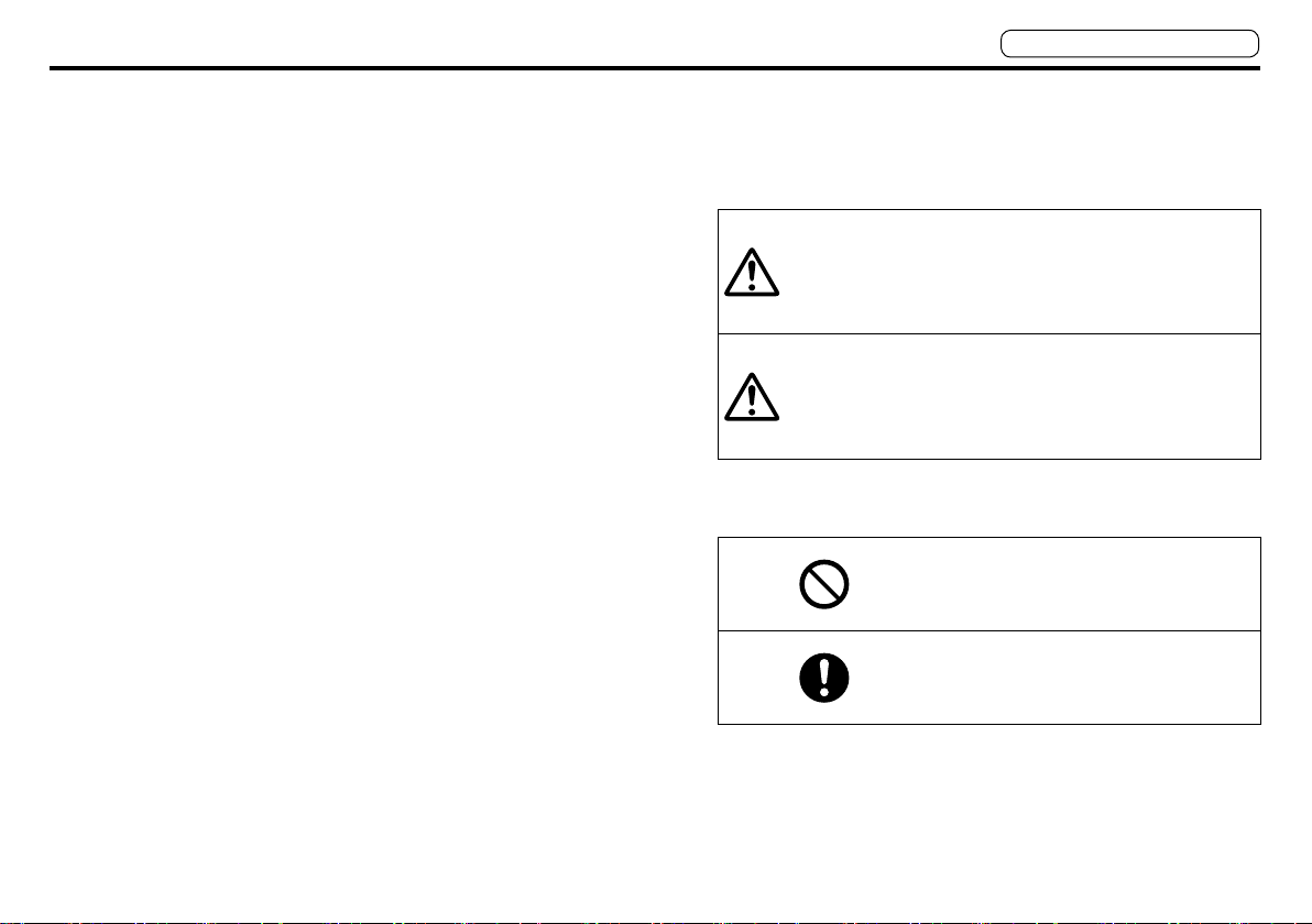
■ The below explains what will happen if someone fails to
heed a particular precaution statement.
Indicates hazards or unsafe
Danger
practices which could result in
severe personal injury or death.
Indicates hazards or unsafe
practices which could result in
Caution
minor personal injury or product
or property damage.
■ The following symbols are used to describe the type of
Do and Don't.
This symbol is used to indicate
a practice that shall not be
attempted.
This symbol is used to indicate
a practice that shall be done.
– 3 –– 2 –
Don't move the product by
holding leadwires or motor shaft.
Don't put the machine into
unstable operation.
Don't apply excessive shock to
the motor shaft.
Don't apply excessive shock to
the product.
Don't get on the product. Don't
place heavy object on the
product.
Once power failure occurs, don't
come close to the machine that
will unexpectedly start upon
recovery of the power.
Provide secure mechanism so
that the restarting of the machine
will not cause personal injury.
Failure to heed
these precautions
will cause bodily
injury.
Excessive shock will
cause failure.
Failure to heed this
instruction will result in
electric shock, personal
injury, fire, malfunction
or damage.
After correctly connecting
leadwires, insulate the live parts
with insulator.
Incorrect wiring will
result in short circuit,
electric shock, fire or
malfunction.
Install the equipment in the
control board and keep the
terminal block and protect it from
inadvertent contact.
Failure to heed this
precaution will result in
electric shock, personal
injury, fire, malfunction
or damage.
Ground the motor ground to the
earth.
Floating ground
circuit will cause
electric shock.
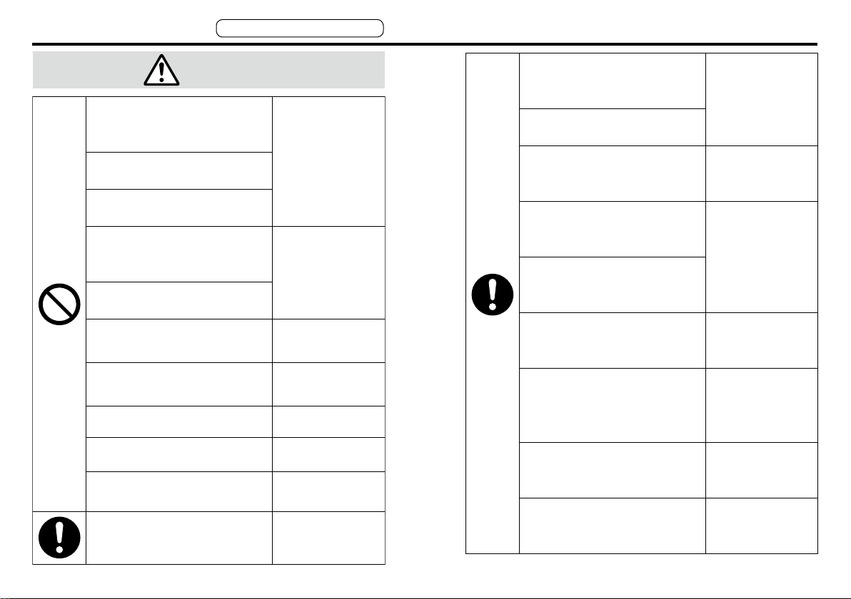
Caution
Danger
Safety Precautions
Don't use the speed controller in
or near environment containing
water, corrosive gas, flammable
gas or flammable material.
Don't place flammable materials
near the motor (including the
controller).
Don't make soldering joint on a
round pin of the speed controller.
Don't damage leadwires or
subject leadwires to excessive
stress such as strong pressure,
heavy object and clamping load.
Don't use leadwires soaked in
water or oil.
Don't use the controller in a place
subject to excessive vibration or
shock.
Don't remove the speed controller
setting knob.
Don't touch rotating member of
the motor.
Don't touch potentially hot motor
casing.
Don't attempt to carry out wiring or
manual operation with wet hand.
Wiring work should be done by a
qualified electrician.
Please observe safety precautions fully.
To prevent possibility
of fire.
Will cause electric
shock, malfunction
or damage.
Will cause electric
shock, personal
injury or fire.
Will cause burn
injury or electric
shock.
Will cause personal
injury.
Will cause burn
injury.
Will cause electric
shock, personal
injury or fire.
Wiring work done by
an inexperienced
person will cause
electric shock.
Use overcurrent protection device,
ground-fault circuit interrupter,
overtemperature protecting device,
and emergency stop device.
After an earthquake, first verify
safety.
Before transferring, wiring or
checking product, disconnect the
power source for safe isolation.
Securely install the equipment to
prevent bodily injury or fire in
case of earthquake.
Provide emergency stop circuit
externally for instantaneous
interruption of operation and
power supply.
Install the unit to a nonflammable
construction (e.g. metal).
Installation area should be free
from excessive dust, and from
splashing water and oil.
Correctly run wirings to the
tacho-generator.
Turn off power upon power
interruption or activation of
overtemperature protecting device.
– 5 –– 4 –
Failure to heed
these requirements
will result in electric
shock, personal
injury or fire.
Incomplete power
disconnection will
cause electric shock.
Failure to heed
these requirements
will result in electric
shock, personal
injury, fire,
malfunction or
damage.
Installation on a
flammable material
may cause fire.
Failure to heed this
precaution will result
in electric shock,
personal injury, fire,
malfunction or
damage.
Incorrect wiring will
result in short circuit,
electric shock,
personal injury, etc.
Unpredictable
restarting will cause
personal injury.

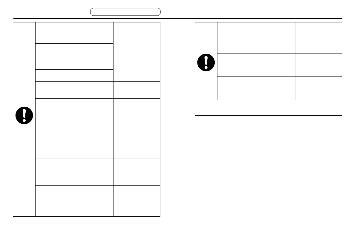
Perform installation by taking into
consideration the mass of the
body and rated output of the
product.
Exactly follow the installing
method and direction specified.
Adjust ambient environmental
condition of motor and speed
controller to match the motor
operating temperature and
humidity.
Connect the motor
electromagnetic brake control
relay in series with a ground-fault
interrupter, circuit breaker and
relay so that they turn off the
circuit upon emergency stop.
Test-run the securely fixed motor
without loading to verify normal
operation, and then connect it to
the mechanical system.
Level of input voltage to the
speed controller should
correspond to the motor rated
voltage.
Operation using a
wrong model or
wrong wiring
connection will result
in personal injury.
Use the speed controller in
combination with the specified
motor.
Failure to heed this
instruction
will result
in fire.
Failure to heed these
instructions will result
in personal injury or
malfunction.
Operation from a
voltage outside the
rated voltage will
cause electric shock,
personal injury or fire.
Provide protection device against
idling of electro-magnetic brake
or gear head, or grease leakage
from gear head.
Lack of protection
will cause personal
injury, damage,
pollution or fire.
Lack of connection
will cause
malfunction.
Locked motor will
Safety Precautions
Please observe safety precautions fully.
Install the equipment in the
control board and keep the
terminal block and protect it from
inadvertent contact.
After correctly connecting
leadwires, insulate the live parts
with insulator.
Ground the motor ground to the
earth.
Caution
Don't move the product by
holding leadwires or motor shaft.
Don't put the machine into
unstable operation.
Once power failure occurs, don't
come close to the machine that
will unexpectedly start upon
recovery of the power.
Provide secure mechanism so
that the restarting of the machine
will not cause personal injury.
Don't apply excessive shock to
the motor shaft.
Don't apply excessive shock to
the product.
Don't get on the product. Don't
place heavy object on the
product.
Failure to heed this
precaution will result in
electric shock, personal
injury, fire, malfunction
or damage.
Incorrect wiring will
result in short circuit,
electric shock, fire or
malfunction.
Floating ground
circuit will cause
electric shock.
Failure to heed
these precautions
will cause bodily
injury.
Excessive shock will
cause failure.
Failure to heed this
instruction will result in
electric shock, personal
injury, fire, malfunction
or damage.
Don't lock the motor shaft while
the motor is running.
Don't clog or put an object into
the radiating hole of the motor.
Don't turn off and on power so
frequently.
Don't pull leadwires with an
excessive force.
Don't use the equipment in highly
intensive electric field.
Don't use the equipment under
direct sunshine.
Don't use the equipment in an
environment where electrostatic
voltage potentials may be
produced.
Don't drop or cause topple over
of something during
transportation or installation.
Don't use a variable transformer
or transformer having capacity
insufficient to feed the load.
Don't use the equipment outside
the limits described on the
nameplate and user's manual.
Never attempt to perform
modification, dismantle or repair.
cause fire, electric
shock, or malfunction.
Failure to heed this
instruction will result
in fire.
Failure to heed this
instruction will result in
fire, personal injury,
malfunction or damage.
Failure to heed this
instruction will cause
fire, electric shock or
personal injury.
Failure to heed
these instructions
will cause personal
injury or fire.
Induced malfunction
will cause
malfunction or
personal injury.
Failure to heed this
instruction will result
in personal injury or
malfunction.
Failure to heed this
instruction will cause
fire, electric shock or
malfunction.
Failure to heed this
instruction will result in
electric shock, personal
injury, fire, malfunction
or damage.
Failure to heed this
instruction will cause
fire, electric shock or
personal injury.
– 7 –– 6 –
Safety Precautions
Perform installation by taking into
consideration the mass of the
body and rated output of the
product.
Adjust ambient environmental
condition of motor and speed
controller to match the motor
operating temperature and
humidity.
Exactly follow the installing
method and direction specified.
Use the speed controller in
combination with the specified
motor.
Connect the motor
electromagnetic brake control
relay in series with a ground-fault
interrupter, circuit breaker and
relay so that they turn off the
circuit upon emergency stop.
Test-run the securely fixed motor
without loading to verify normal
operation, and then connect it to
the mechanical system.
Level of input voltage to the
speed controller should
correspond to the motor rated
voltage.
Please observe safety precautions fully.
Failure to heed these
instructions will result
in personal injury or
malfunction.
Failure to heed this
instruction
in fire.
Lack of connection
will cause
malfunction.
Operation using a
wrong model or
wrong wiring
connection will result
in personal injury.
Operation from a
voltage outside the
rated voltage will
cause electric shock,
personal injury or fire.
will result
Don't place any obstacle object
around the motor and peripheral,
which blocks air passage.
Correctly run and arrange wiring.
Maintenance must be performed
by an experienced personnel.
Always keep power disconnected
when the power is not necessary
for a long time.
Scraps must be treated as
industrial waste.
Temperature rise will
cause burn injury or
fire.
Wrong wiring will
cause personal injury
or electric shock.
Improper operation
will cause personal
injury.
Provide protection device against
idling of electro-magnetic brake
or gear head, or grease leakage
from gear head.
Lack of protection
will cause personal
injury, damage,
pollution or fire.
– 9 –– 8 –
MGSDB2
120 VAC
240 VAC
Example
1. Introduction
Unpacking
· Verify that the model No. matches your order sheet.
· Damage in transit is not found.
Should you nd any discrepancy in the product,
consult your local dealer.
General description of the speed controller
The MGSD type speed controller is designed to operate with a small
geared motor to adjust and vary its speed. The speed is adjusted
from the speed setting knob. The input voltage can be single-phase
100-120 VAC, or single-phase 200 – 240 VAC. The speed controller
is compatible with EC directive and UL standard.
Compatible with DIN terminal block which is convenient to install on
the distribution board, and small timer common option available from
Panasonic Corporation (pp. 32 – 37).
Read this manual thoroughly so that you will become gradually acquainted with the excellent features of your speed controller for small
geared motor and understand how to fully utilize these functions. The
speed controller is designed to be integrated into a general control
board.
The product must be handled by experienced personnel familiar with
the product.
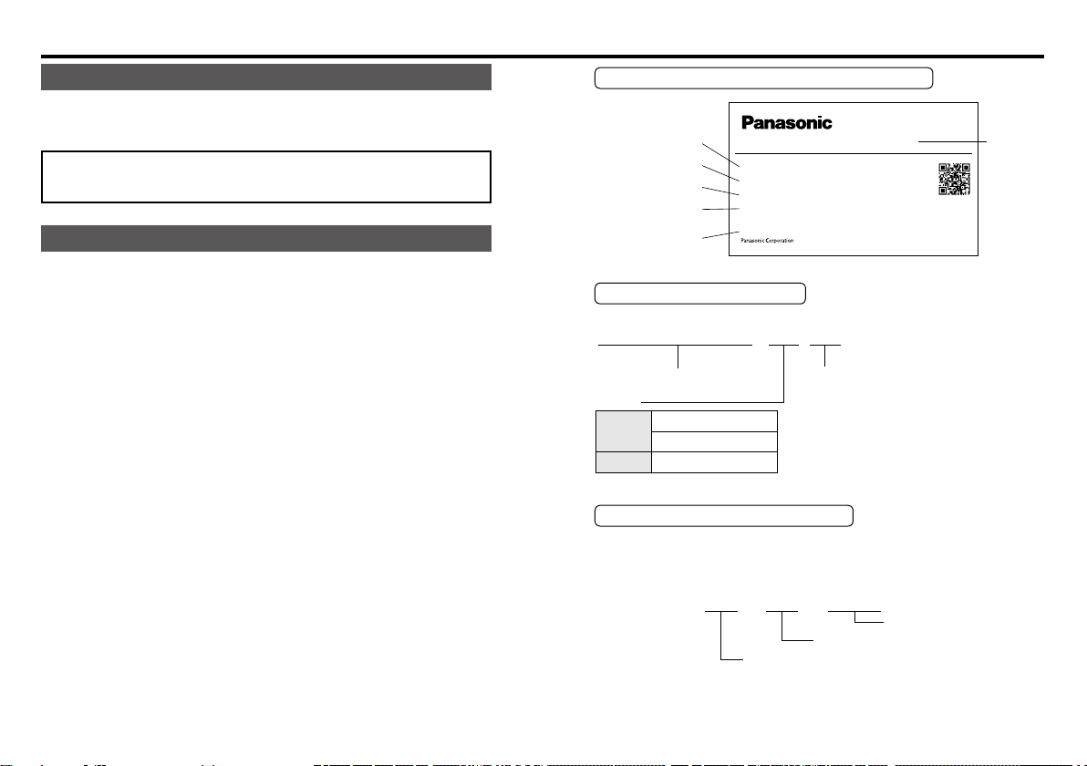
Designation and rating on the nameplate
Rated
input voltage
Input current
Rated speed
Rated output
Serial No.
(production No.)
Model No.
Input
Input Current
Rated Speed
Rated Output
Ser.No. 06110001G
Made in China
50/60Hz 1Ph 200–240V
1.0A
1400/1700min
6–90W
SPEED CONTROLLER
MGSDB2
–
1
C58401
Description of model No.
651 – 4
Input power supply
1. Single phase 100 –
2. Single phase 200 –
Output
100 V
200 V
Series
A : 3 – 40 W
B : 60 – 90 W
B : 6 – 90 W
Serial number (production No.)
The Ser. No. on the nameplate contains the following codes.
Ser.No. * 06 11 0001 *
Sequential number
Manufacturing month
Manufacturing year
This product was manufactured in November 2006
and assigned a sequential number 0001.
Model
name
– 11 –– 10 –
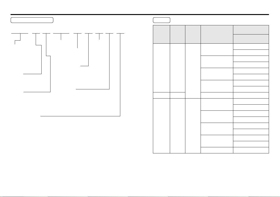
1. Introduction
M91Z90GV4LG
Motor Part Number
3
Size
M6: Sq.60 mm
M7: Sq.70 mm
80 mm
M8: Sq.
M9: Sq.
90 mm
Series
1 : Induction motor
R : Reversible motor
Series
X : 40 W or lower
Z : 60 W or higher
Version
Blank : Pinion shaft motor (Japanese standard)
S : Round shaft motor (Japanese standard)
G : International standard approved motor (CE, UL, CCC)
5,61,2
Output
7 8 9 10 114
No. of
poles
Shape of shaft
G : Pinion
S : Round
Variable speed
V : Variable (without brake)
Variable with electromagnetic
BV :
brake
Voltage
L : 100 V
D : 110 – 115 V
Y : 200 V
G : 220 – 230 V
Rating
Model No. Output
MGSDA1
MGSDB1
MGSDB2
3-40 W
60-90
6
-
90 W
W
Power
supply
AC100 V
to
AC120 V
AC200 V
to
AC240 V
Compatible
induction motor
M61X***V4**
M71X***V4**
M81X***V4**
M91X***V4**
M91Z***V4**
M61X***V4**
M71X***V4**
M81X***V4**
M91X***V4**
M91Z***V4**
Compatible
reversible motor
Compatible reversible motor
with electromagnetic brake
M6RX***V4**
M6RX**GBV4**
M7RX***V4**
M7RX**GBV4**
M8RX***V4**
M8RX**GBV4**
M9RX***V4**
M9RX**GBV4**
M9RZ***V4**
M6RX***V4**
M6RX**GBV4**
M7RX***V4**
M7RX**GBV4**
M8RX***V4**
M8RX**GBV4**
M9RX***V4**
M9RX**GBV4**
M9RZ***V4**
– 13 –– 12 –
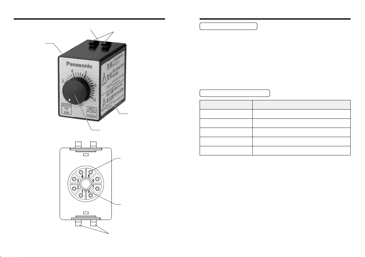
2. Names and functions
Terminal block
Terminal block locking
hook mounting hole
Nameplate
locking claw
3. Installation
Installation location
(1) Indoors free from rain and direct sunlight: the product is not of a
waterproof construction.
(2) Free from vibration 4.9 m/s2 or more; shock, dust, iron powder
or oil mist; splash of water, oil and grinding uid; and away from
ammable materials, corrosive gas (H2S, SO2, NO2, Cl2, etc.) or
ammable gas.
(3) Well ventilated dry and clean location containing negligible amount
of oil or dust.
Environmental condition
<Rear panel>
Caution plate
Speed control knob
Pin
Pin number
Terminal block
locking claw
Item
Operating temperature
Storage temperature
Operating humidity
Allowable vibration
Altitude
Condition
–10 °C – 50 °C
–20 ˚C – 60 ˚C
90 % RH or below (no dewing)
2
or below (10 Hz – 60 Hz)
4.9 m/s
1000 m max.
– 15 –– 14 –
 Loading...