

Panasonic MADDT1207, MBDDT2210, MDDDT5540, MBDDT2110, MADDT1107 Technical Reference
...
Technical referenc
e
AC Servo Motor & Drive
r
MINAS A4-series
If you are the first user of this product, please be sure to purchase and read
the optional Engineering Material (DV0P4210), or downloaded Instruction
Manual from our Web Site.
[Web address of Motor Company, Matsushita Electric Industrial Co., Ltd.]
http://industrial.panasonic.com/ww/i_e/25000/motor_fa_e/motor_fa_e.html
Thank you very much for your
purchase of Panasonic AC Servo
Motor & Driver, MINAS A4-series.
Before use, refer this technical
reference and safety instructions
to ensure proper use. Keep this
technical reference and read
when necessary.
Make sure to forward this technical
reference for safety to the final
user.
•
•
•
IMC54D
Z0404-6066
1. Introduction................................. B2
On Opening the Package ............................... B2
Check of the Driver Model .............................. B2
Check of the Motor Model .............................. B3
2. Installation .................................. B4
Driver .............................................................. B4
Motor .............................................................. B6
Console .......................................................... B8
3. System Configuration and
Wiring ........................................B10
Overall Wiring
(Connecting Example of C-frame, 3-
phase) ..............................................................
B10
Overall Wiring
(Connecting Example of E-frame) ....
B12
Driver and List of Applicable Peripheral
Equipments .................................................. B14
Wiring of the Main Circuit (A to D-frame) ..... B16
Wiring of the Main Circuit (E and F-frame) ... B17
Wiring method to connector (A to D-frame).. B18
Wiring to the Connector, CN X6
(Connection to Encoder) .............................. B22
Wiring for Typical Control Modes
to the Connector CN X5 ............................... B24
4. Parameter.................................. B27
Outline of Parameter .................................... B27
How to Set .................................................... B27
Setup with the Front Panel ........................... B27
Outline of PANATERM
®
.......................................................
B28
Setup with the Console ................................ B28
How to Connect ............................................ B29
Composition and List of Parameters ............ B30
5. Protective Functions................ B36
Protective Function (What Is Error Code ?) .....
B36
6. Maintenance and Inspections . B38
7. Conformity to EC Directives
and UL Standards ..................... B40
Composition of Peripheral Equipments ........ B41
Conformity to UL Standards ......................... B44
8. Built-in Holding Brake ............. B45
9. Dynamic Brake ......................... B47
10.
Check of the Combination of
the Driver and the Motor ............
B48
After-Sale Service (Repair) .......... B51
page page
<Contents>
R
ated input voltage/current
r)
Check of the Motor Model
Contents of Name Plate
Model Designation
s
s)
MAMA
MQMA
MSMD
MSMA
MDMA
MHMA
MFMA
MGMA
Symbol
Motor structure
MSMD, MQMA MAMA
*
1 The product with oil seal is a special order
product.
*
2 Key way with center tap
A
B
S
T
Symbol
Products are standard stock items or build to
order items. For details, inquire of the dealer.
1. Introduction
On Opening the Product Package
• Make sure that the model is what you have ordered.
• Check if the product is damaged or not during transportation.
• Check if the instruction manual is attached or not.
• Check if the power connector and motor connecters (CN X1 and CN X2 connectors)
are attached or not (A to D-frame).
Contact to a dealer if you find any failures.
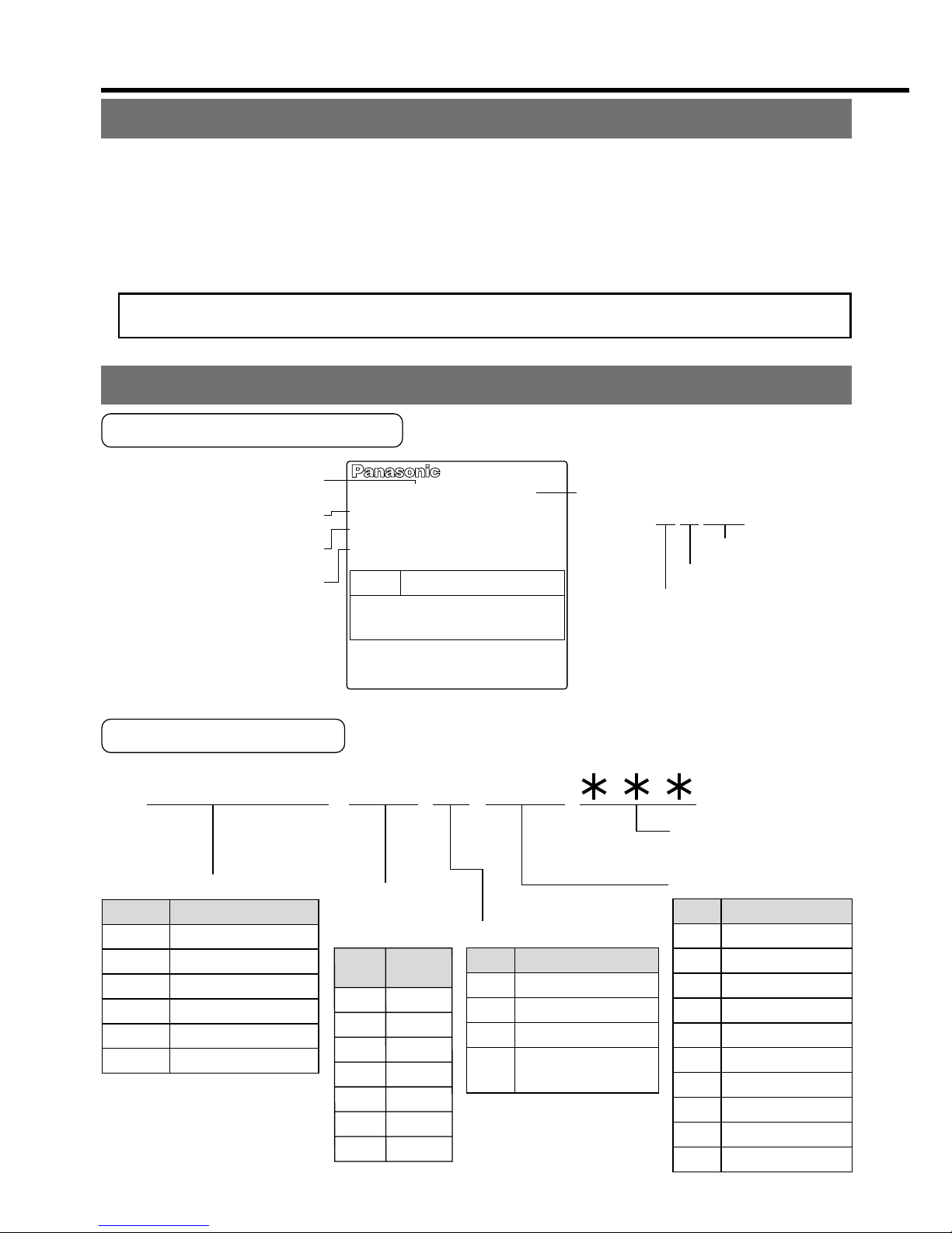
Check of the Driver Model
Contents of Name Plate
Model Designation
M A D D T 1 2 0 5
Special specification
s
(letters and numbers
)
Current detector ratin
g
Power supply
Max. current
rating of
power device
F
rame-size symbol
MADD
MBDD
MCDD
MDDD
MEDD
MFDD
Frame
Symbol
A4-series, A-frame
A4-series, B-frame
A4-series, C-frame
A4-series, D-frame
A4-series, E-frame
A4-series, F-frame
T1
T2
T3
T5
T7
TA
TB
Current
rating
Symbol
Specifications
10A
15A
30A
50A
70A
100A
150A
Symbol
1
2
3
5
Single phase, 100V
Single phase, 200V
3-phase, 200V
Single/3-phase,
200V
05
07
10
15
20
30
40
64
90
A2
Current rating
Symbol
5A
7.5A
10A
15A
20A
30A
40A
64A
90A
120A
1 to 4 75 to 6 10 to 128 to 9
Model number
R
ated input/output voltage
Rated output of
applicable motor
Rated input/output current
Serial Number
MADDT1205
e.g.) :
P04 11 0001Z
Lot number
Month of productio
n
Year of production
(Lower 2 digits of AD yea
r)
50/60Hz
100W
1.3A
1ø
200-240V
Freq.
Model No.
AC SERVO
Serial No.P04110001Z
INPUT
Voltage
Phase
F.L.C
Power
OUTPUT
69V
3ø
1.2A
0~333.3Hz
– B3 –– B2 –
AC SERVO MOTOR
RATING S1
MODEL No.
MSMD5AZS1S
INS. CLASS B (TÜV) A (UL)
CONT. TORQUE
0.64
Nm
A1.6
CONNECTION
RATED OUTPUT
RATED FREQ.
kW
0.2
SER No.
04110001
Hz
200
RATED REV.
r/min
3000
INPUT 3ØAC
92
IP65
V
Model
Rated output
R
ated input voltage/current
Rated rotational speed
Serial Number
e.g.) :
0411 0001
Lot number
Month of production
Year of production
(Lower 2 digits of AD yea
r)
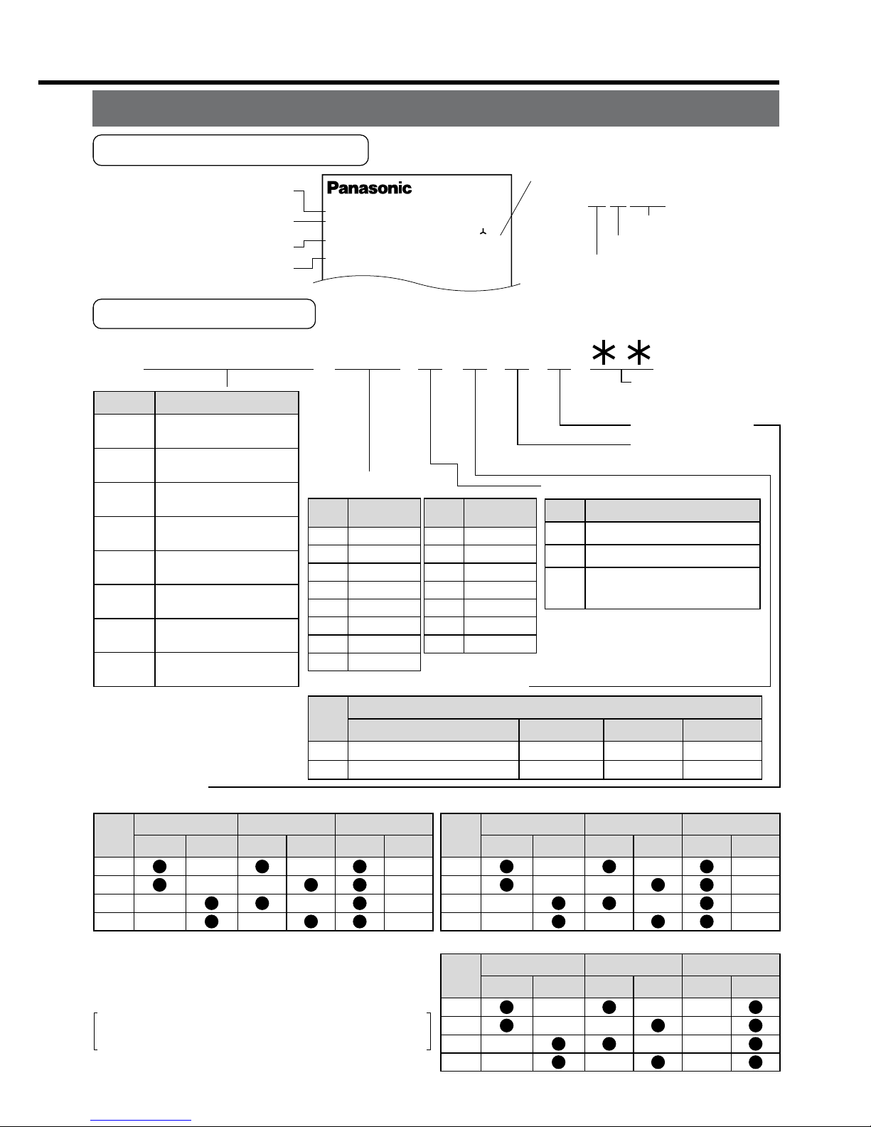
Check of the Motor Model
Contents of Name Plate
Model Designation
M S M D 5 A Z S 1 S
1 to 4
5 to 6
11 to 12
7
8 9 10
Special specification
s
(letters and number
s)
Motor structure
Design order
1: Standard
Rotary encoder specifications
Voltage specifications
MAMA
MQMA
MSMD
MSMA
MDMA
MHMA
MFMA
MGMA
Type
Symbol
Ultra low inertia
(100W to 750W)
Low inertia
(100W to 400W)
Low inertia
(50W to 750W)
Low inertia
(1.0kW to 5.0kW)
Middle inertia
(1.0kW to 5.0kW)
High inertia
(500W to 5.0kW)
Middle inertia
(400W to 4.5kW)
Middle inertia
(900W to 4.5kW)
P
S
Incremental
Absolute/Incremental common
Specifications
Symbol
Format
2500P/r
17bit
Pulse count
5A
01
02
04
05
08
09
10
Output
Motor rated output
Symbol
50W
100W
200W
400W
500W
750W
900W
1.0kW
15
20
25
30
40
45
50
Output
Symbol
1.5kW
2.0kW
2.5kW
3.0kW
4.0kW
4.5kW
5.0kW
1
2
Z
Specifications
Symbol
100 V
200 V
100/200 common
(50W only)
10,000
131,072
Resolution
5-wire
7-wire
Wire count
Motor structure
MSMD, MQMA MAMA
*
1 The product with oil seal is a special order
product.
*
2 Key way with center tap
A
B
E
F
Shaft
Holding brake
Oil seal
Without
With
Round
Key way
Without
With
Symbol
A
B
S
T
Shaft
Holding brake
Oil seal
Without
With
Round
Key way
Without
With
Symbol
MSMA, MDMA, MFMA, MGMA, MHMA
C
D
G
H
Shaft
Holding brake
Oil seal
Without
With
Round
Key way
Without
With
Symbol
*
1
*
2
*
2
Products are standard stock items or build to
order items. For details, inquire of the dealer.
Install the driver and the motor properly to avoid a breakdown or an accident.
Driver
Installation Place
1) Indoors, where the products are not subjected to rain or direct sun beams. The products are not waterproof.
2) Where the products are not subjected to corrosive atmospheres such as hydrogen
sulfide, sulfurous acid, chlorine, ammonia, chloric gas, sulfuric gas, acid, alkaline and
salt and so on, and are free from splash of inflammable gas, grinding oil, oil mist, iron
powder or chips and etc.
3) Well-ventilated and low humidity and dust-free place.
4) Vibration-free place.
Environmental Conditions
Ambient temperature
Ambient humidity
Storage temperature
Storage humidity
Vibration
Altitude
ConditionsItem
0˚C to 55˚C (free from freezing)
Less than 90% RH (free from condensation)
–20˚C to 80˚C (free from freezing)
Less than 90% RH (free from condensation)
Lower than 5.9m/s
2
(0.6G), 10 to 60Hz
Lower than 1000m
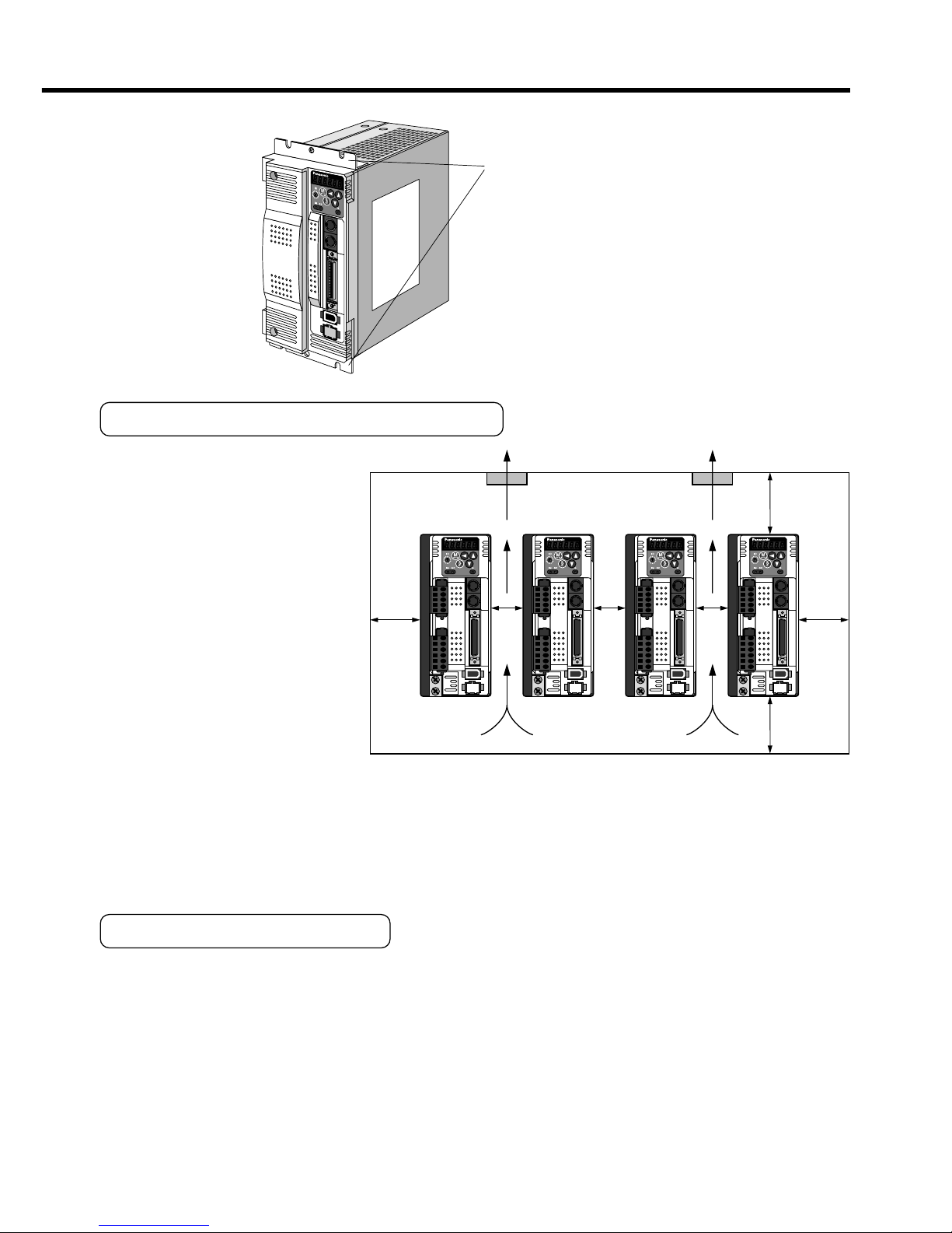
Fan Fan
100mm
or more
100mm
or more
40mm
or
more
40mm
or
more
10mm
or
more
10mm
or
more
10mm
or
more
A
to D-frame e.g.) In case of C-frame
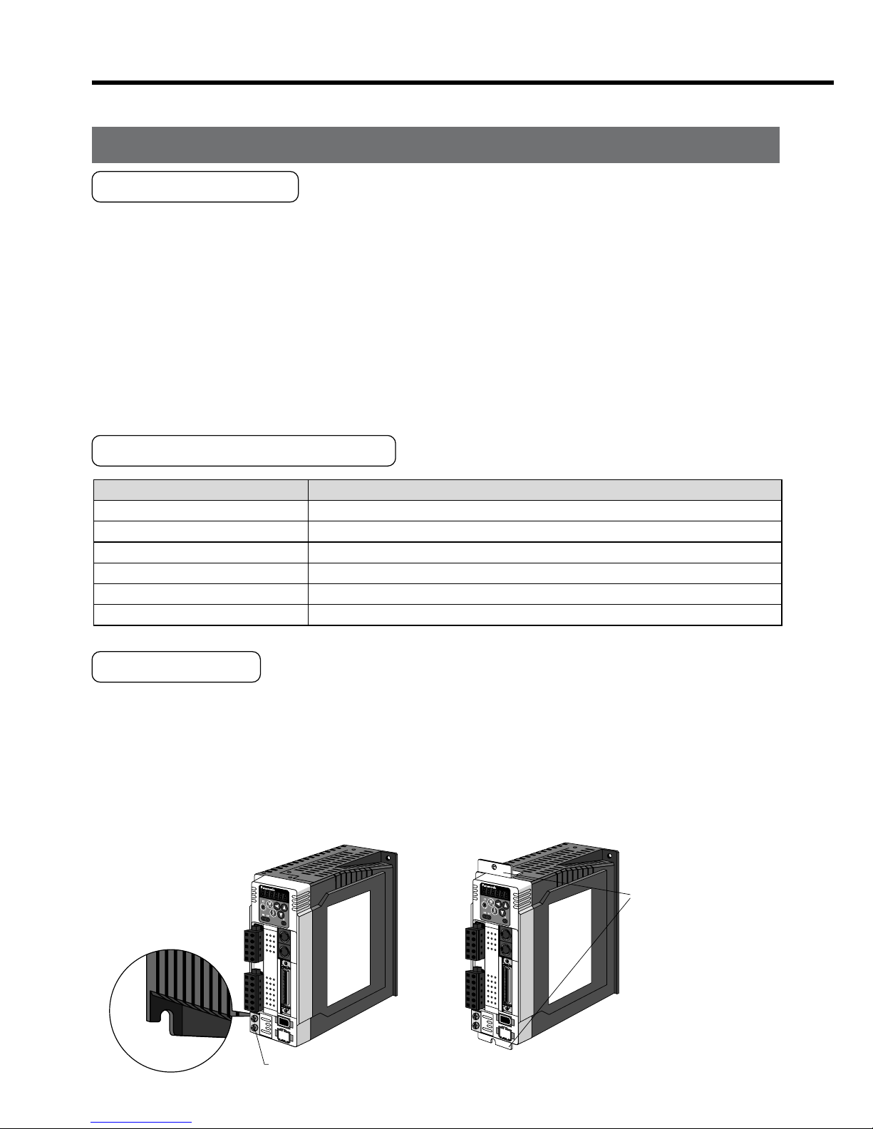
Fastening torque of earth screws (M4) to be 0.39 to 0.59N
•
m.
Mounting brack
et
(optional parts)
MADD
MBDD
MCDD
MDDD
E
et
2. Installation
How to Install
1) Rack-mount type. Install in vertical position, and reserve enough space around the
servo driver for ventilation.
Base mount type (rear mount) is standard (A to D-frame)
2) Use the optional mounting bracket when you want to change the mounting face.
Mounting Direction and Spacing
• Reserve enough surround-
ing space for effective cool-
ing.
• Install fans to provide uni-
form distribution of tem-
perature in the control
panel.
• Observe the environmental
conditions of the control
panel described in the next
page.
<Note>
It is recommended to use the conductive paint when you make your own mounting
bracket, or repaint after peeling off the paint on the machine for installing the products, in
order to make noise countermeasure.
Caution on Installation
We have been making the best effort to ensure the highest quality, however, application
of exceptionally large external noise disturbance and static electricity, or failure in input
power, wiring and components may result in unexpected action. It is highly recommended
that you make a fail-safe design and secure the safety in the operative range.
There might be a chance of smoke generation due to the failure of these products. Pay
an extra attention when you apply these products in a clean room environment.
– B5 –– B4 –
Fan Fan
100mm
or more
100mm
or more
40mm
or
more
40mm
or
more
10mm
or
more
10mm
or
more
10mm
or
more
E
and F-frame
Mounting brack
et
Mounting Direction and Spacing
• Reserve enough surrounding space for effective cooling.
• Install fans to provide uniform distribution of temperature in the control
panel.
• Observe the environmental
conditions of the control
panel described in the next
page.
<Note>
It is recommended to use the conductive paint when you make your own mounting
bracket, or repaint after peeling off the paint on the machine for installing the products, in
order to make noise countermeasure.
Caution on Installation
We have been making the best effort to ensure the highest quality, however, application
of exceptionally large external noise disturbance and static electricity, or failure in input
power, wiring and components may result in unexpected action. It is highly recommended
that you make a fail-safe design and secure the safety in the operative range.
There might be a chance of smoke generation due to the failure of these products. Pay
an extra attention when you apply these products in a clean room environment.
Ambient temperature
Ambient humidity
Storage temperature
Storage humidity
Vibration
Impact
Enclosure
rating
ConditionItem
0˚C to 40˚C (free from freezing)
*1
Less than 85% RH (free from condensation)
–20˚C to 80˚C (free from freezing)
*2
Less than 85% RH (free from condensation)
Lower than 49m/s
2
(5G) at running, 24.5m/s2 (2.5G) at stall
Lower than 98m/s
2
(10G)
IP65 (except rotating portion of output shaft and lead wire end)
These motors conform to the test conditions specified in EN standard
s
(EN60529, EN60034-5). Do not use these motors in application wher
e
water proof performance is required such as continuous wash-dow
n
operation.
Motor only
Motor only
Motor only
•
2. Installation
Motor
Installation Place
Since the conditions of location affect a lot to the motor life, select a place which meets
the conditions below.
1) Indoors, where the products are not subjected to rain or direct sun beam. The products are not waterproof.
2) Where the products are not subjected to corrosive atmospheres such as hydrogen
sulfide, sulfurous acid, chlorine, ammonia, chloric gas, sulfuric gas, acid, alkaline and
salt and so on, and are free from splash of inflammable gas, grinding oil, oil mist, iron
powder or chips and etc.
3) Where the motor is free from grinding oil, oil mist, iron powder or chips.
4) Well-ventilated and humid and dust-free place, far apart from the heat source such as
a furnace.
5) Easy-to-access place for inspection and cleaning
6) Vibration-free place.
7) Avoid enclosed place. Motor may gets hot in those enclosure and shorten the motor life.
Environmental Conditions
*1 Ambient temperature to be measured at 5cm away from the motor.
*2 Permissible temperature for short duration such as transportation.
How to Install
You can mount the motor either horizontally or vertically as long as you observe the followings.
1) Horizontal mounting
• Mount the motor with cable outlet facing downward for water/oil countermeasure.
2) Vertical mounting
• Use the motor with oil seal (non-standard) when mounting the motor with gear
reducer to prevent the reducer oil/grease from entering to the motor.
3) For mounting dimensions, refer to the technical reference. (DV0P4210)
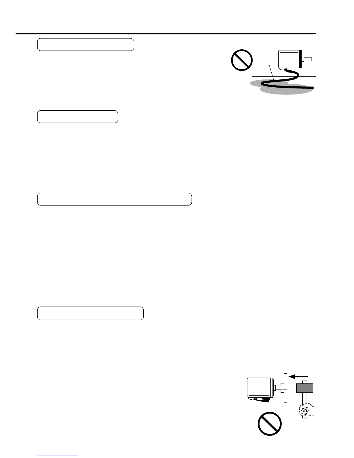
Oil/Water Protection
1) Don't submerge the motor cable to water or oil.
2) Install the motor with the cable outlet facing downward.
3) Avoid a place where the motor is subjected to oil or water.
4) Use the motor with an oil seal when used with the gear re-
ducer, so that the oil may not enter to the motor through shaft.
Stress to Cables
1) Avoid a stress application to the cable outlet and connecting portion by bending or
self-weight.
2) Especially in an application where the motor itself travels, fix the attached cable and
contain the extension junction cable into the bearer so that the stress by bending can
be minimized.
3) Take the cable bending radius as large as possible. (Minimum R20mm)
Permissible Load to Output Shaft
1) Design the mechanical system so that the applied radial load and/or thrust load to the
motor shaft at installation and at normal operation can meet the permissible value
specified to each model.
2) Pay an extra attention when you use a rigid coupling. (Excess bending load may
damage the shaft or deteriorate the bearing life.
3) Use a flexible coupling with high stiffness designed exclusively for servo application in
order to make a radial thrust caused by micro misalignment smaller than the permis-
sible value.
4) For permissible load of each model, refer to the technical reference. (DV0P4210)
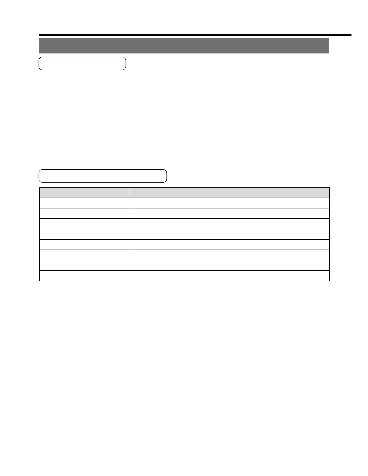
Notes on Installation
1) Do not apply direct impact to the shaft by hammer while attaching/detaching a cou-
pling to and from the motor shaft.
(Or it may damage the encoder mounted on the other side of the shaft.)
2) Make a full alignment. (incomplete alignment may cause vibration and damage the
bearing.)
3) If the motor shaft is not electrically grounded, it may cause
electrolytic corrosion to the bearing depending on the condi-
tion of the machine and its mounting environment, and may
result in the bearing noise. Check and verification by customer
is required.
– B7 –– B6 –
Motor
Oil / Water
Cable
Motor
Oil/Water Protection
1) Don't submerge the motor cable to water or oil.
2) Install the motor with the cable outlet facing downward.
3) Avoid a place where the motor is subjected to oil or water.
4) Use the motor with an oil seal when used with the gear reducer, so that the oil may not enter to the motor through shaft.
Stress to Cables
1) Avoid a stress application to the cable outlet and connecting portion by bending or
self-weight.
2) Especially in an application where the motor itself travels, fix the attached cable and
contain the extension junction cable into the bearer so that the stress by bending can
be minimized.
3) Take the cable bending radius as large as possible. (Minimum R20mm)
Permissible Load to Output Shaft
1) Design the mechanical system so that the applied radial load and/or thrust load to the
motor shaft at installation and at normal operation can meet the permissible value
specified to each model.
2) Pay an extra attention when you use a rigid coupling. (Excess bending load may
damage the shaft or deteriorate the bearing life.
3) Use a flexible coupling with high stiffness designed exclusively for servo application in
order to make a radial thrust caused by micro misalignment smaller than the permissible value.
4) For permissible load of each model, refer to the technical reference. (DV0P4210)
Notes on Installation
1) Do not apply direct impact to the shaft by hammer while attaching/detaching a coupling to and from the motor shaft.
(Or it may damage the encoder mounted on the other side of the shaft.)
2) Make a full alignment. (incomplete alignment may cause vibration and damage the
bearing.)
3) If the motor shaft is not electrically grounded, it may cause
electrolytic corrosion to the bearing depending on the condition of the machine and its mounting environment, and may
result in the bearing noise. Check and verification by customer
is required.
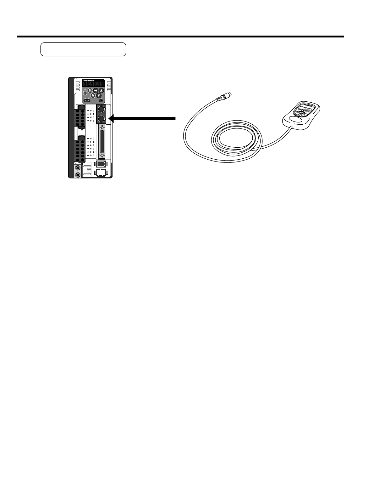
How to Connect
<Remarks>
• Connect the console connector securely to CN X4 connector of the driver.
• Never pull the cable to plug in or plug out.
Ambient temperature
Ambient humidity
Storage temperature
Storage humidity
Vibration
Impact
Altitude
ConditionItem
0˚C to 55˚C (free from freezing)
Less than 90% RH (free from condensation)
–20˚C to 80˚C (free from freezing)
Less than 90% RH (free from condensation)
Lower than 5.9m/s
2
(0.6G), 10 to 60Hz
Conform to JISC0044
(Free fall test, 1m for 2 directions, 2 cycles)
Lower than 1000m
2. Installation
Console
Installation Place
1) Indoors, where the products are not subjected to rain or direct sun beam. The products are not waterproof.
2) Where the products are not subjected to corrosive atmospheres such as hydrogen
sulfide, sulfurous acid, chlorine, ammonia, chloric gas, sulfuric gas, acid, alkaline and
salt and so on, and are free from splash of inflammable gas, grinding oil, oil mist, iron
powder or chips and etc.
3) Well-ventilated and low humidity and dust-free place.
4) Easy-to-access place for inspection and cleaning
Environmental Conditions
<Cautions>
• Do not give strong impact to the products.
• Do not drop the products.
• Do not pull the cables with excess force.
• Avoid the place near to the heat source such as a heater or a large winding resistor.
– B9 –– B8 –
How to Connect
<Remarks>
• Connect the console connector securely to CN X4 connector of the driver.
• Never pull the cable to plug in or plug out.
MODE
SHIFT
SET
S
M
Connect to CN X4.
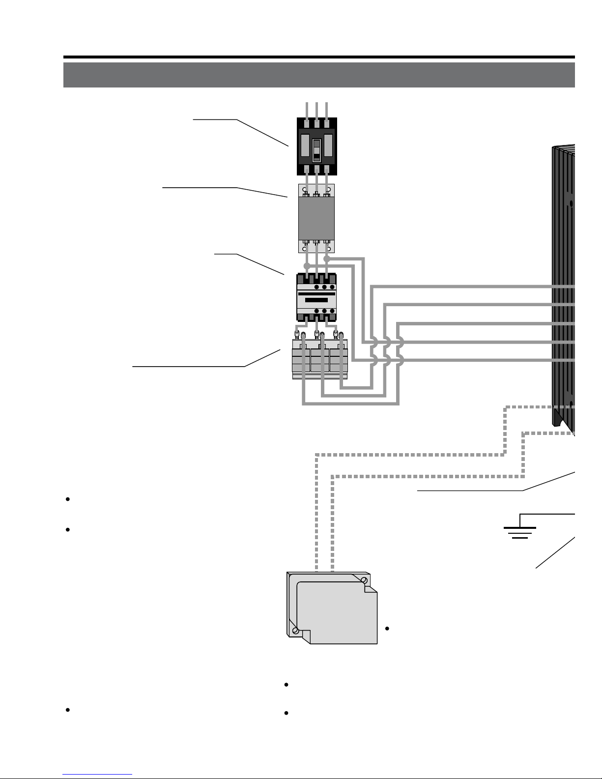
C
ircuit Breaker (NFB)
U
se the circuit breaker matching
c
apacity of the power source to
p
rotect the power lines.
N
oise Filter (NF)
P
revents external noise from the pow-
e
r lines. And reduces an effect of the
n
oise generated by the servo driver.
M
agnetic Contactor (MC)
T
urns on/off the main power of the
s
ervo driver.
U
se a surge absorber together
w
ith this.
•
Never start nor stop the servo mo-
tor with this Magnetic Contactor.
R
eactor (L)
R
educes harmonic current of the
m
ain power.
F
or specifications, refer to the
d
ownloaded Instruction Manual
f
rom our Web Site.
•
Wiring of the Main Circuit
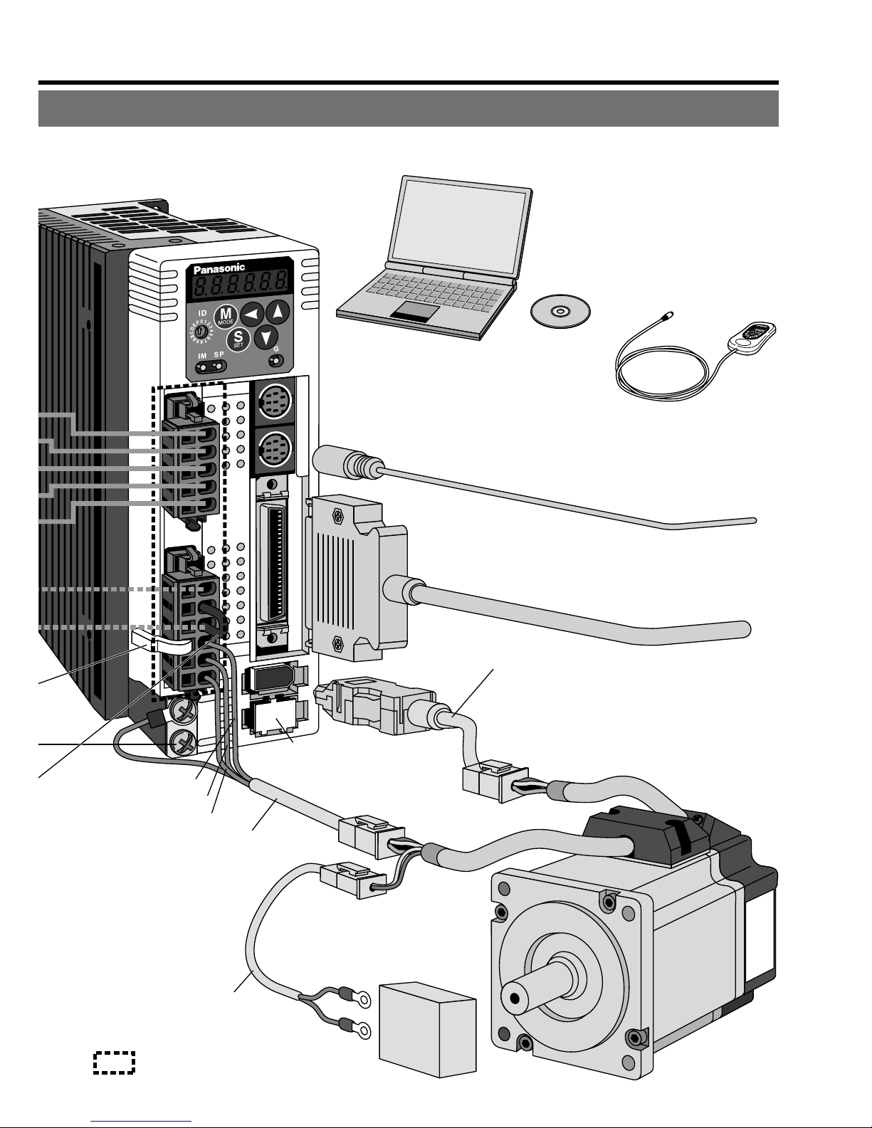
Ground
(earth)
• Connection to
the Connector, CN X1
(connection to input power)
• Connection to the Connector, CN X2
(connection to external components)
Short bar
Junction cable for motor
Junction cable
for brake
RB1 (Pin-6)
RB2 (Pin-4)
• Wiring to Connector,
CN X2
(Connection to
motor driving
phase and
ground)
L1 (Pin-5)
L2 (Pin-4)
L3 (Pin-3)
L1C (Pin-2)
L2C (Pin-1)
P
in RB1 (6-pin), RB2 (4-pin), and
R
B3 (5-pin)
RB2 and RB3 to be kept shorted for
normal operation.
When the capacity shortage of
the regenerative resister is found,
disconnect a shorting bar between RB2 and RB3, then connect
the external regenerative resister
between RB1 and RB2.
(Note that no regenerative resister
is equipped in Frame A and B type.
Install an external regenerative
resister on incombustible material, such as metal. Follow the same
wiring connection as the above.)
When you connect an external regenerative resister, set up Parameter No. 6C to 1 or 2.
Handle lever
Use this for connector
connection. Store this
after connection for other
occasions.
(see page for connection.)
Regenerative resistor
(optional)
<Remarks>
When you use an external
regenerative resister, install
an external protective apparatus, such as
thermal fuse without fail.
For resistor value and capacity, refer to the
downloaded Instruction Manual from our Web Site.
Thermal fuse and thermostat are built in to the
regenerative resistor (Option). If the thermal
fuse is activated, it will not resume.
U-phase (red)
V-phase (white)
W-phase (black)
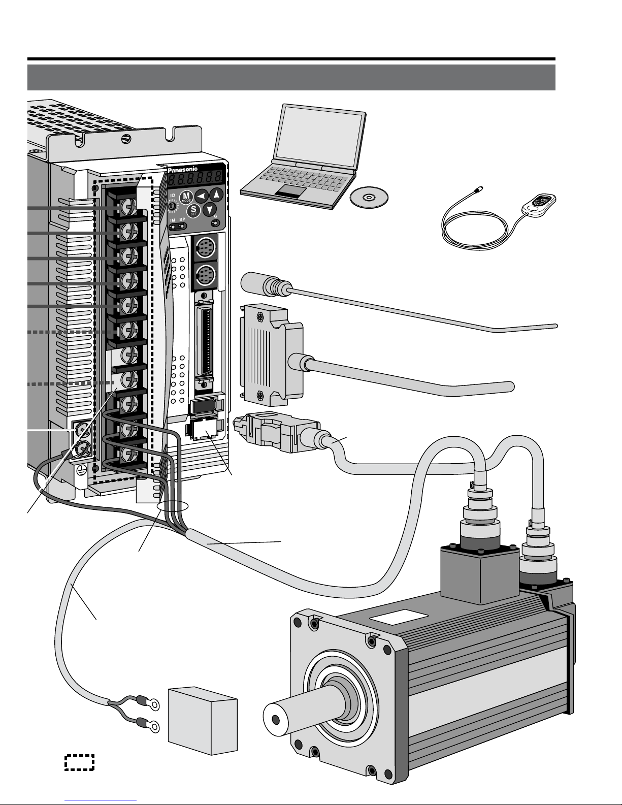
3. System Configuration and Wiring
Overall Wiring (Connecting Example of C-frame, 3-phase)
– B11 –– B10 –
X3
X4
X5
X6
X7
• Wiring to Connector, CN X3/X4 (option)
(Connection to PC or host controller)
• Wiring to Connector, CN X5
(Connection to host controller)
• Wiring to Connector, CN X6
(Connection to encoder)
• Wiring to
Connector, CN X7
(Connection to
external scale)
Junction cable for encoder
Junction cable for motor
Junction cable
for brake
DC Power supply for brake
DC24V
(to be supplied by customer)
• Wiring to Connector,
CN X2
(Connection to
motor driving
phase and
ground)
: High voltage
X1
X2
U-phase (red)
V-phase (white)
W-phase (black)
PC (to be supplied by customer)
Setup support software
"PANATERM
®
"
DV0P4460
Console (option)
DV0P4420
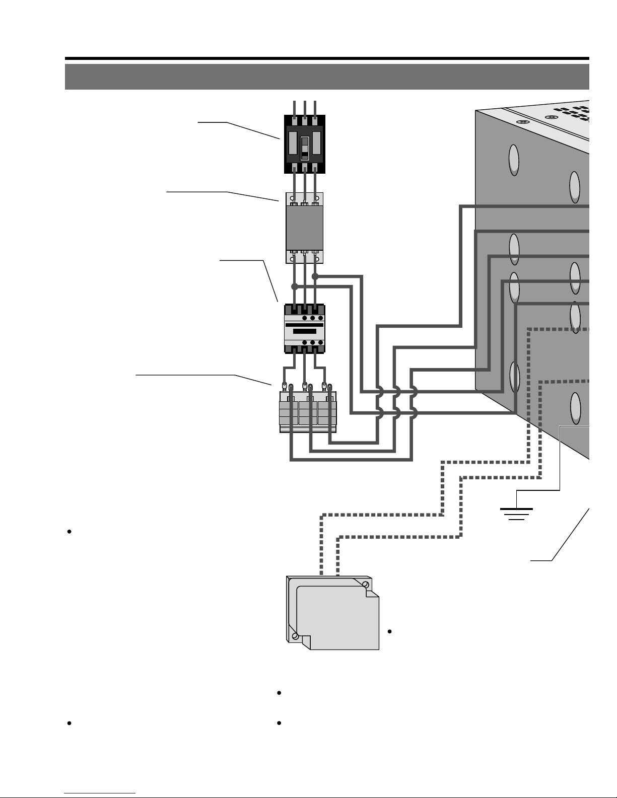
3. System Configuration and Wiring
Overall Wiring (Connecting Example of E-frame)
Ground
(earth)
• Connection
with input
power supply
• Connection to external
components
Short bar
P
B2
L1
L2
L3
r
t
P
in P, B1 and B2...
B1 and B2 to be kept shorted for
normal operation.
When the capacity shortage of
the regenerative resister is
found, disconnect a short bar
between B1 and B2, then con-
nect the external regenerative
resister between P and B2.
Install an external regenerative resister on incombustible
material, such as metal. Follow
the same wiring connection as
the above.
When you connect an external
regenerative resister, set up
Parameter No. 6C to 1 or 2.
Regenerative resistor
(optional)
<Remarks>
When you use an external
regenerative resister, install
an external protective apparatus, such as thermal
fuse without fail.
For resistor value and capacity, refer to the
downloaded Instruction Manual from our Web Site.
Thermal fuse and thermostat are built in to the
regenerative resistor (Option). If the thermal fuse
is activated, it will not resume.
C
ircuit Breaker (NFB)
U
se the circuit breaker matching
c
apacity of the power source to
p
rotect the power lines.
N
oise Filter (NF)
P
revents external noise from the pow-
e
r lines. And reduces an effect of the
n
oise generated by the servo driver.
M
agnetic Contactor (MC)
T
urns on/off the main power of the
s
ervo driver.
U
se a surge absorber together
w
ith this.
•
Never start nor stop the servo mo-
tor with this Magnetic Contactor.
R
eactor (L)
R
educes harmonic current of the
m
ain power.
F
or specifications, refer to the
d
ownloaded Instruction Manual
f
rom our Web Site.
•
Wiring of the Main Circuit
– B13 –– B12 –
: High voltage
X3
X4
X5
X7
X6
• Wiring to Connector, CN X3/X4 (option)
(Connection to PC or host controller)
• Wiring to Connector, CN X5
(Connection to host controller)
Junction cable
for motor
Junction cable for brake
DC Power supply for brake
DC24V
(to be supplied by customer)
U-phase
V-phase
W-phase
X1
• Wiring to Connector, CN X6
(Connection to encoder)
Junction cable
for encoder
From a top
• Wiring to Connector, CN X7
(Connection to external scale)
• Connection to motor driving
phase and ground
PC (to be supplied by customer)
Setup support software
"PANATERM
®
"
DV0P4460
Console (option)
DV0P4420
3. System Configuration and Wiring
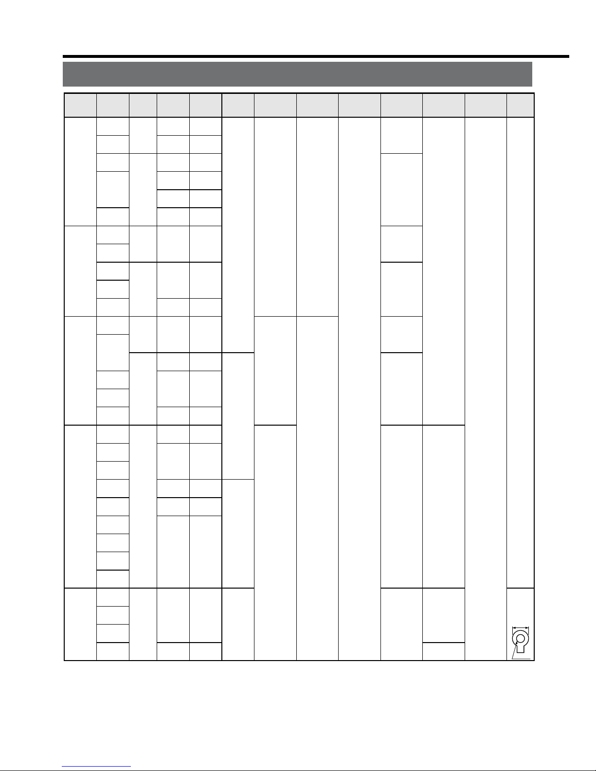
Connection
Driver
Applicable
motor
Voltage
Rated
output
Required
Power
(at the rated
load)
Noise
filter for
signal
Noise
filter
Surge
absorber
Magnetic
contactor
Cable
diameter
(main circuit)
Cable
diameter
(control circuit)
MADD
MBDD
MCDD
MDDD
MEDD
MSMD
MQMA
MSMD
MQMA
MAMA
MSMD
MQMA
MSMD
MQMA
MAMA
MQMA
MSMD
MAMA
MFMA
MHMA
MAMA
MDMA
MHMA
MGMA
MSMA
MHMA
MDMA
MSMA
MFMA
MDMA
MSMA
MHMA
MFMA
Single
phase,
100V
Single
phase,
200V
Single
phase,
100V
Single
phase,
200V
Single
phase,
100V
Single/
3- phase,
200V
Single/
3- phase,
200V
3- phase,
200V
50W
to 100W
100W
50W
to 200W
100W
200W
100W
200W
400W
200W
400W
750W
400W
500W
750W
1.0kW
900W
1.0kW
1.5kW
2.0kW
2.5kW
approx.
0.4kVA
approx.
0.4kVA
approx.
0.5kVA
approx.
0.3kVA
approx.
0.5kVA
approx.
0.3kVA
approx.
0.5kVA
approx.
0.9kVA
approx.
0.5kVA
approx.
0.9kVA
approx.
1.3kVA
approx.
0.9kVA
approx.
1.1kVA
approx.
1.6kVA
approx.
1.8kVA
approx.
1.8kVA
approx.
1.8kVA
approx.
2.3kVA
approx.
3.3kVA
approx.
3.8kVA
Circuit
breaker
(rated
current)
10A
15A
20A
30A
DV0P4170
DV0P4180
DV0P4220
Connection to exclusive connector
DV0P4190
DV0P1450
DV0P1460
BMFT61041N
(3P+1a)
BMFT61542N
(3P+1a)
BMFT61041N
(3P+1a)
BMFT61542N
(3P+1a)
BMFT61541N
(3P+1a)
BMFT61542N
(3P+1a)
BMFT61842N
(3P+1a)
BMF6352N
(3P+2 a 2b)
0.75 to
2.0mm
2
AWG
14 to 18
2.0mm
2
AWG14
2.0mm
2
AWG14
3.5mm
2
AWG12
0.75mm
2
AWG18
Termina
l
block
M5
11.0 or
smaller
ø5.3
Driver
MFDD
l
Driver and List of Applicable Peripheral Equipments
• Select a single and 3-phase common specifications according to the power source.
• Manufacturer of circuit breaker and magnetic contactor : Matsushita Electric Works.
To comply to EC Directives, install a circuit breaker between the power and the noise
filter without fail, and the circuit breaker should conform to IEC Standards and UL
recognized (Listed and marked).
5000Arms, 240V is the maximum capacity to be delivered to the circuit of 750W or
larger model when the maximum current value of the circuit breaker is limited to 20A.
• For details of noise filters, refer to P.B42, "Noise Filter".
<Remarks>
• Select and use the circuit breaker and noise filter with matching capacity to those of
the power source, considering the load conditions as well.
• Terminal block and protective earth terminal
Use a copper conductor cable with temperature rating of 60˚C or higher.
Protective earth terminal is M4 for A to D-frame, and M5 for E and F-frame.
Larger tightening torque of the screw than the max. value (M4 : 1.2 N
may damage the terminal block.
• Earth cable diameter should be 2.0mm
and 3.5mm
for 4.5kW to 5kW model.
• Use the attached exclusive connectors for A to D-frame, and maintain the peeled off
length of 8 to 9mm.
• Tightening torque of the screws for connector (CN X5) for the connection to the host
to be 0.3 to 0.35 N
at the driver side.
– B15 –– B14 –
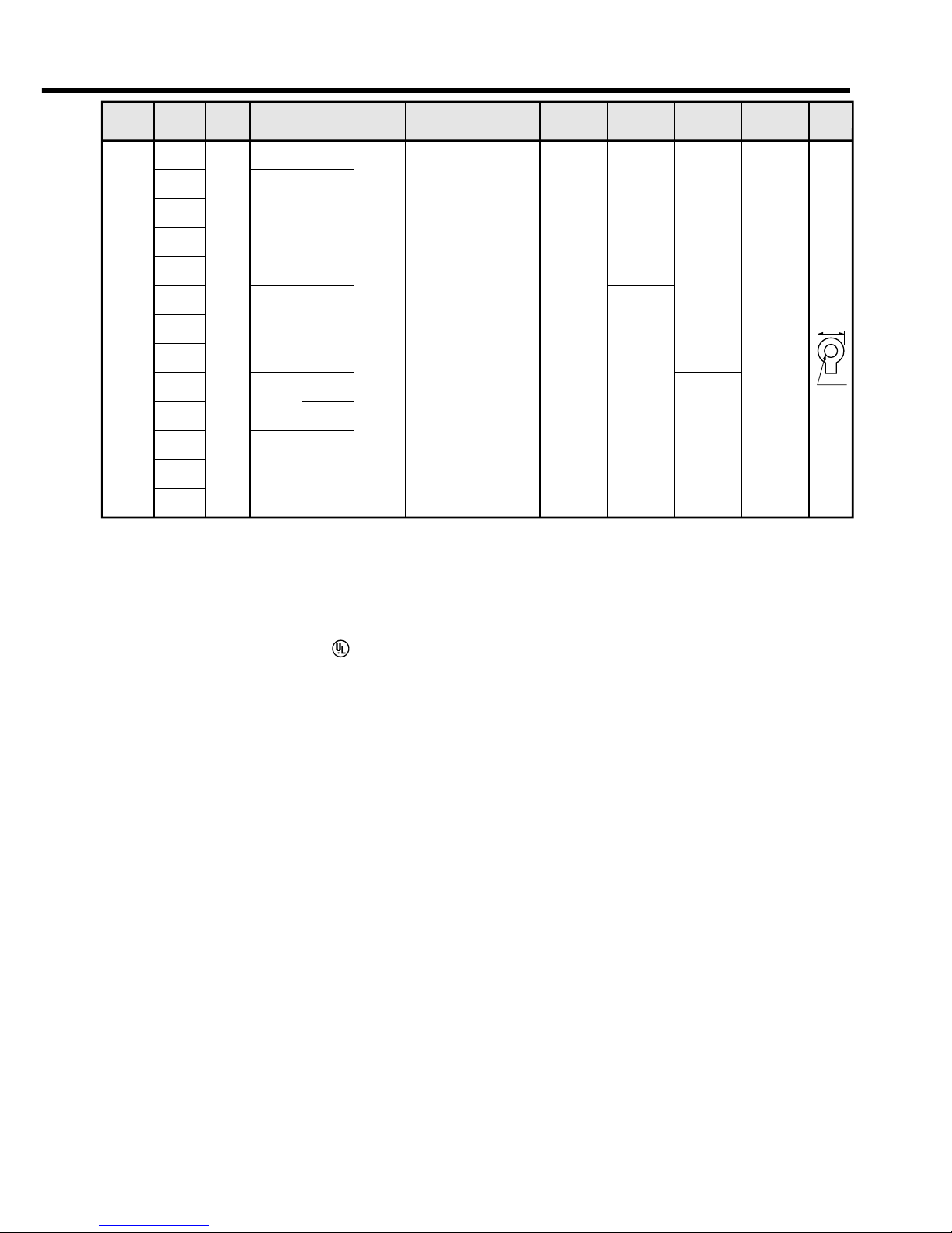
Connection
Driver
Applicable
motor
Voltage
Rated
output
Required
Power
(at the rated
load)
Noise
filter for
signal
Noise
filter
Surge
absorber
Magnetic
contactor
Cable
diameter
(main circuit)
Cable
diameter
(control circuit)
Circuit
breaker
(rated
current)
MFDD
MGMA
MDMA
MHMA
MSMA
MGMA
MDMA
MHMA
MSMA
MFMA
MGMA
MDMA
MHMA
MSMA
3- phase,
200V
2.0kW
3.0kW
4.0kW
4.5kW
5.0kW
approx.
3.8kVA
approx.
4.5kVA
approx.
6kVA
approx.
6.8kVA
approx.
7.5kVA
approx.
7.5kVA
50A
DV0P3410 DV0P1450 DV0P1460
BMF6352N
(3P+2a2b)
BMF6652N
(3P+2a2b)
3.5mm
2
AWG12
5.3mm
2
AWG10
0.75mm
2
AWG18
Termina
l
block
M5
11.0 or
smaller
ø5.3
• Select a single and 3-phase common specifications according to the power source.
• Manufacturer of circuit breaker and magnetic contactor : Matsushita Electric Works.
To comply to EC Directives, install a circuit breaker between the power and the noise
filter without fail, and the circuit breaker should conform to IEC Standards and UL
recognized (Listed and marked).
5000Arms, 240V is the maximum capacity to be delivered to the circuit of 750W or
larger model when the maximum current value of the circuit breaker is limited to 20A.
• For details of noise filters, refer to P.B42, "Noise Filter".
<Remarks>
• Select and use the circuit breaker and noise filter with matching capacity to those of
the power source, considering the load conditions as well.
• Terminal block and protective earth terminal
Use a copper conductor cable with temperature rating of 60˚C or higher.
Protective earth terminal is M4 for A to D-frame, and M5 for E and F-frame.
Larger tightening torque of the screw than the max. value (M4 : 1.2 N
•
m, M5 : 2.0 N•m)
may damage the terminal block.
• Earth cable diameter should be 2.0mm
2
(AWG14) or larger for 50W to 2.0kW model,
and 3.5mm
2
(AWG12) or larger for 2.5kW to 4.0kW, and 5.3mm2(AWG10) or larger
for 4.5kW to 5kW model.
• Use the attached exclusive connectors for A to D-frame, and maintain the peeled off
length of 8 to 9mm.
• Tightening torque of the screws for connector (CN X5) for the connection to the host
to be 0.3 to 0.35 N
•
m. Larger tightening torque than these may damage the connector
at the driver side.
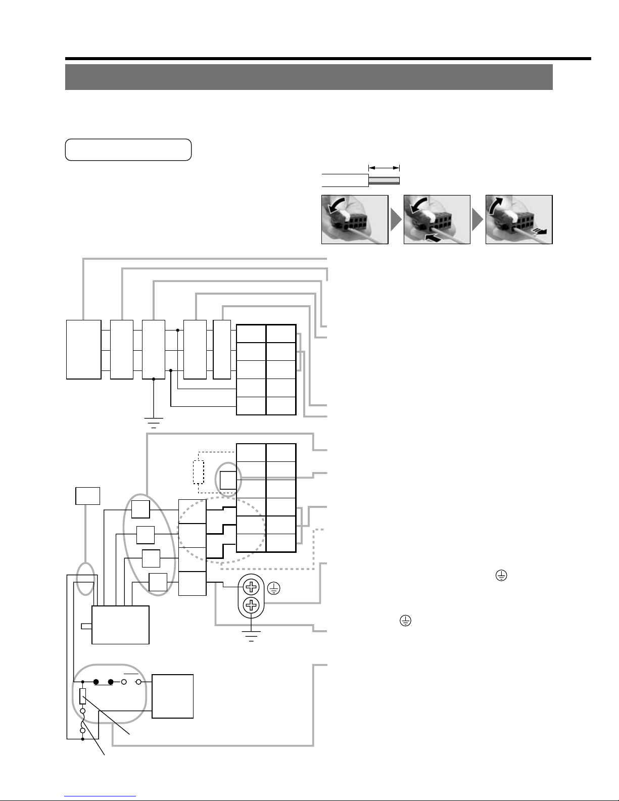
Red
Black
Green
yellow
Motor
Surge absorber
DC
24V
White
NFB
Power
supply
DC power supply
for brake
NF MC
1
2
3
4
U
V
W
E
L1C
L3
L2
L1
L2C
RB1
RB3
RB2
U
V
W
2
3
4
5
1
6
5
4
3
2
1
CN X1
CN X2
L
Yellow
(X2)
Fuse (5A)
Ground resistance : 100Ω max.
For applicable wire,
refer to P.B14 and B15.
• Check the name plate of the driver for power
specifications.
• Provide a circuit breaker, or a leakage breaker.
The leakage breaker to be the one designed for
"Inverter" and is equipped with countermeasures
for harmonics.
• Provide a noise filter without fail.
• Provide a surge absorber to a coil of the Magneti
c
Contactor. Never start/stop the motor with this
Magnetic Contactor.
Connect a fuse in series with the surge absorber
.
Ask the manufacturer of the Magnetic Contactor
for the fuse rating.
• Provide an AC Reactor.
• Connect L1 and L1C, and L3 and L2C at singl
e
phase use (100V and 200V), and don't use L2.
•
Match the colors of the motor lead wires to those of
the corresponding motor output terminals (U,V,W).
•
Don't disconnect the shorting cable between RB2
and RB3 (C and D frame type). Disconnect this only
when the external regenerative register is used.
• Avoid shorting and ground fault. Don't
connect the main power.
*
Connect pin 3 of the connector on the amplifier
side with pin 1 of the connector on the motor side.
• Earth-ground this.
•
Connect the protective earth terminal ( ) of the
driver and the protective earth (earth plate) of the
control panel without fail to prevent electrical shock.
• Don't co-clamp the earth wires to the protective
earth terminal ( ) . Two terminals are provided.
• Don't connect the earth cable to other
inserting slot, nor make them touch.
• Compose a duplex Brake Control Circuit so that
the brake can also be activated by an external
emergency stop signal.
• The Electromagnetic Brake has no polarity.
• For the capacity of the electromagnetic brake and
how to use it, refer to P.B45, "Specifications of
Built-in Holding Brake".
• Provide a surge absorber.
•
Connect a 5A fuse in series with the surge absorber
.
3. System Configuration and Wiring
Wiring of the Main Circuit (A to D-frame)
• Wiring should be performed by a specialist or an authorized personnel.
• Do not turn on the power until the wiring is completed.
Tips on Wiring
1) Peel off the insulation cover of the cable.
(Observe the dimension as the right fig. shows.)
2) Insert the cable to the connector detached
from the driver.(See P.B18 for details.)
3) Connect the wired connector to the driver.
8~9mm
Power
supply
r
.
.
d
.
Wiring of the Main Circuit (E and F-frame)
• Wiring should be performed by a specialist or an authorized personnel.
• Do not turn on the power until the wiring is completed.
Tips on Wiring
1) Take off the cover fixing screws, and detach the terminal cover.
2) Make wiring
Use clamp type terminals of round shape with insulation cover for wiring to the termi-
nal block. For cable diameter and size, rater to "Driver and List of Applicable Periph-
eral Equipments" (P.B14 and B15).
3) Attach the terminal cover, and fix with screws.
Fastening torque of cover fixed screw in less than 0.2 N
 Loading...