

Panasonic MEWNET-F Technical Manual

PROGRAMMABLE CONTROLLER
PROGRAMMABLE CONTROLLER
MEWNET-F(Remote I/O system)
TechnicalManual
http://www.mew.co.jp/ac/e/fasys/
MEWNET-F (Remote I/O system) Technical Manual
FAF-35E-1 08.03

Safety Precautions
Observe the following notices to ensure personal safety or to prevent accidents.
To ensure that you use this product correctly, read this User’s Manual thoroughly before use.
Make sure that you fully understand the product and information on safe.
This manual uses two safety flags to indicate different levels of danger.
WARNING
If critical situations that could lead to user’s death or serious injury is assumed by
mishandling of the product.
-Always take precautions to ensure the overall safety of your system, so that the whole system
remains safe in the event of failure of this product or other external factor.
-Do not use this product in areas with inflammable gas. It could lead to an explosion.
-Exposing this product to excessive heat or open flames could cause damage to the lithium battery
or other electronic parts.
CAUTION
If critical situations that could lead to user’s injury or only property damage is assumed
by mishandling of the product.
-To prevent excessive exothermic heat or smoke generation, use this product at the values less than
the maximum of the characteristics and performance that are assured in these specifications.
-Do not dismantle or remodel the product. It could cause excessive exothermic heat or smoke
generation.
-Do not touch the terminal while turning on electricity. It could lead to an electric shock.
-Use the external devices to function the emergency stop and interlock circuit.
-Connect the wires or connectors securely.
The loose connection could cause excessive exothermic heat or smoke generation.
-Do not allow foreign matters such as liquid, flammable materials, metals to go into the inside of the
product. It could cause excessive exothermic heat or smoke generation.
-Do not undertake construction (such as connection and disconnection) while the power supply is on.
It could lead to an electric shock.
Copyright / Trademarks
-This manual and its contents are copylighted.
-You may not copy this manual,in whole or part,without written consent of Matsushita Electric
Works,Ltd.
-Windows and Windows NT are registered trademarks of Microsoft Corporation in the
United States and/or other countries.
-All other company names and product names are trademarks or registered
trademarks of their respective owners.
-Matsushita Electric Works,Ltd. pursues a policy of continuous improvement of the
Design and performan e of its products, therefore,we reserve the right to change the manual/ c
product without notice.

Table of Contents
Before you start
1.Functions and Restrictions of the Unit............................1-1
1.1 Features and Functions............................................................................. 1-2
1.2 System Configuration ................................................................................1-3
1.2.1 Master Station (Master Unit) ......................................................................1-4
1.2.2 Slave Stations (Slave Unit, I/O Terminal, I/O Terminal Board, etc)...........1-5
1.2.3 Advanced Units Not to be Used for Slave Station System of “MEWNET-F”1-7
1.3 Unit Types.................................................................................................. 1-9
1.3.1 Remote I/O System "MEWNET-F" Components .......................................1-9
1.3.2 Transmission Cable .................................................................................1-10
1.3.3 I/O Cables and Power Supply Cable for I/O Terminal Board "For MIL
Connector Type" ...................................................................................
1.3.4 Expansion Cable for I/O Terminal Unit ....................................................1-10
2.Part Names and Functions ................................................2-1
2.1 FP2 Multi-wire Link Unit............................................................................. 2-2
2.2 Remote I/O master unit.............................................................................. 2-6
2.2.1 FP3 Remote I/O Master Unit (AFP3742) ...................................................2-6
2.3 Remote I/O Slave Unit ............................................................................... 2-8
2.3.1 FP2 Remote I/O Slave Unit (AFP2745) .....................................................2-8
2.3.2 FP3 Remote I/O Slave Unit (AFP3745) ...................................................2-10
2.4 I/O Terminal Board ..................................................................................2-12
2.4.1 I/O Terminal Board Terminals Specifications ..........................................2-14
1-10
2.5 I/O Terminal Unit...................................................................................... 2-18
2.5.1 I/O Terminal Unit Terminals Specifications..............................................2-20
3.Unit Specifications .............................................................3-1
3.1 General Specifications (Common to the System)...................................... 3-2
3.2 Performance Specifications (Common to the System) ..............................3-3
3.3 Rating and Specifications of Components................................................. 3-4
3.3.1 Master Unit.................................................................................................3-4
3.3.2 Slave Unit...................................................................................................3-4
3.3.3 I/O Terminal Board..................................................................................... 3-4
3.3.4 I/O Terminal Unit ........................................................................................3-6
3.4 Transmission Cable Specifications............................................................ 3-8
3.4.1 Recommended Cables...............................................................................3-8
3.4.2 Processing the End of Transmission Cables .............................................3-9
3.5 Communication Time............................................................................... 3-10
3.5.1 Remote I/O Scan Time [TR].....................................................................3-10

3.5.2 Remote I/O Memory Access Time [TRM] ..................................................3-10
3.5.3 Input/Output Response Time for Remote I/O System [TRES].................3-11
4.Installation and Wiring....................................................... 4-1
4.1 Preparation of MEWNET-F Components .................................................. 4-2
4.1.1 Master Station (Master Unit) ......................................................................4-2
4.1.2 Slave Station System (Slave Unit) .............................................................4-4
4.1.3 I/O Terminal Board (Slave Station) ............................................................4-6
4.1.4 I/O Terminal Unit (Slave Station) ...............................................................4-7
4.1.5 Reference (Check Flow Chart>..................................................................4-8
4.2 Power Up Sequence ................................................................................. 4-9
4.2.1 Remote I/O Mapping, Slave Station Connection Confirmation Mode........4-9
4.2.2 Remote I/O Mapping, Slave Station Connection Not Confirmed Mode.....4-9
4.2.3 Remote I/O Map Not Registered Mode......................................................4-9
5.Connection for the Remote I/O System............................ 5-1
5.1 Connection for the Remote I/O System..................................................... 5-2
5.1.1 Description of Connection and Setting Procedure .....................................5-2
5.2 Connection Pattern for MEWNET-F .......................................................... 5-3
5.2.1 Connection Pattern A .................................................................................5-3
5.2.2 Connection Pattern B .................................................................................5-3
5.2.3 Connection Pattern C.................................................................................5-3
5.2.4 Connection Pattern D.................................................................................5-4
5.2.5 Connection Pattern E .................................................................................5-4
5.2.6 Connection Pattern F .................................................................................5-4
5.3 Procedure for Connecting and Setting Up................................................. 5-5
5.3.1 Preparation.................................................................................................5-5
5.3.2 Precedure 1 Wiring of Transmission Cables............................................5-6
5.3.3 Procedure 2 Master Station (Master Unit) Setting ...................................5-7
5.3.4 Procedure 3 Slave Station Setting ...........................................................5-8
5.3.5 Procedure 4 Power Up Sequence..........................................................5-10
6.Remote I/O Map .................................................................. 6-1
6.1 Remote I/O Map ........................................................................................ 6-2
6.1.1 Configuration of Remote I/O Map ..............................................................6-2
6.1.2 Precautions When Allocating I/O Numbers for Slave Stations ..................6-3
6.2 Automatic I/O Number Allocation and Arbitrary I/O Number Allocation .... 6-5
6.2.1 Remote I/O Control According to Automatic Allocation .............................6-5
6.2.2 Remote I/O Control According to Arbitrary Allocation................................6-6
6.3 Arbitrary Allocation of Remote I/O Map..................................................... 6-8
6.3.1 Setting the Base Word Number .................................................................6-8
6.3.2 Setting the Number of Slots Used..............................................................6-9
6.3.3 Setting the I/O Type and Number of Points ...............................................6-9

7.Operation Modes for Controlling MEWNET-F ..................7-1
7.1 How to Change the Operation Mode (System Register Setting) ............... 7-2
7.1.1 Operation Mode Changeable.....................................................................7-2
7.1.2 How to Change the Remote I/O Operation Mode......................................7-2
7.1.3 System Registers for the Remote I/O Operating Mode .............................7-2
7.2 Remote I/O Control When an Error Occurs ...............................................7-3
7.2.1 Operation Status When a Communication Error Occurs ........................... 7-4
7.2.2 Operation When an Error Occurs in a Unit Connected to a Slave Station
System ....................................................................................................
7.3 Slave Station Connection Confirmation Mode ........................................... 7-9
7.3.1 Slave Station Connection Confirmation Mode ...........................................7-9
7.3.2 Slave Station Connection Not Confirmed Mode ......................................7-10
7.4 Remote I/O Update Timing Method .........................................................7-11
7.4.1 Scan Asynchronous Mode .......................................................................7-11
7.4.2 Scan Time Synchronous Mode................................................................7-12
8.Control by MEWNET-F .......................................................8-1
8.1 Functions of MEWNET-F........................................................................... 8-2
8.1.1 Remote I/O Control ....................................................................................8-2
8.1.2 Memory Access Function........................................................................... 8-3
9.Troubleshooting .................................................................9-1
7-7
9.1 Finding the Cause of an Error and Correcting the Error ............................ 9-2
9.1.1 Finding the Cause of an Error....................................................................9-2
9.2 Self-diagnostic Functions of MEWNET-F .................................................. 9-3
9.2.1 Self-diagnostic Error Table ........................................................................9-3
9.3 Remote I/O Error Codes (DT9136(DT90136) and DT9137(DT90137))..... 9-4
9.3.1 Contents of Special Data Registers DT9136 and DT9137 ........................9-4
9.4 Check a Slave Station Which Has Produced an Error (DT9131(DT90131) to
DT9135(DT90135))..........................................................................................
9-6
9.5 Troubleshooting......................................................................................... 9-9
9.5.1 Flowchart (Main Flowchart)........................................................................9-9
9.5.2 When the ALARM LED is ON ..................................................................9-11
9.5.3 When the Communication LED on the Master Unit does Not Flash Normally9-12
9.5.4 When the Communication LED on a Slave Station does Not Flash Normally9-15
9.5.5 When the CPU does Not Operate............................................................9-18
9.5.6 When the Input/Output Function of a Slave Station does Not Work........ 9-19
9.5.7 When the Memory Access Function for the Advanced Unit's Memory does
Not Work ...............................................................................................
9-20

9.6 LED Status .............................................................................................. 9-21
9.7 Precautions When Using Remote I/O System ........................................ 9-23
10.Dimensions ....................................................................... 10-1
10.1 FP2 Multi-wire Link Unit ........................................................................ 10-2
10.2 FP3 Remote I/O Master Unit ................................................................. 10-2
10.3 FP2 Remote I/OSlave Unit .................................................................... 10-3
10.4 FP3 Remote I/OSlave Unit .................................................................... 10-3
10.5 FP I/O Terminal Board .......................................................................... 10-4
10.5.1 MIL Connector Type...............................................................................10-4
10.5.2 Terminal Block Type ..............................................................................10-4
10.5.3 Mounting Hole Dimensions (In Common) ..............................................10-4
10.6 FP I/O Terminal Unit.............................................................................. 10-5
10.6.1 16-point Type .........................................................................................10-5
10.6.2 8-point Type ...........................................................................................10-5
10.6.3 Mounting Hole Dimensions ....................................................................10-5
10.7 FP1 I/O Link Unit ................................................................................... 10-6
10.7.1 DC Power Supply Type..........................................................................10-6
10.7.2 AC Power Supply Type ..........................................................................10-6
10.8 FP0 I/O Link Unit ................................................................................... 10-7
11.(Appendix 1) I/O Link With FP1 ....................................... 11-1
11.1 I/O Link With FP-M ................................................................................ 11-2
11.2 Overview of FP1 I/O Link Unit ............................................................... 11-3
11.2.1 Idea of I/O Link.......................................................................................11-3
11.2.2 Remote I/O and Expansion I/O ..............................................................11-4
11.3 Part Names and Functions.................................................................... 11-5
11.4 Specifications ........................................................................................ 11-7
11.4.1 General Specifications ...........................................................................11-7
11.4.2 Performance Specifications ...................................................................11-7
11.5 Connection, Setting and Installation...................................................... 11-8
11.5.1 Connecting to FP1 .................................................................................11-8
11.5.2 Wiring to FP2/FP2SH/FP3/FP10SH.......................................................11-9
11.5.3 Wiring of Power Supply..........................................................................11-9
11.5.4 Installing to I/O Link Unit ......................................................................11-10
11.5.5 Selecting Operation Mode....................................................................11-11
11.6 I/O Allocation ....................................................................................... 11-12
11.6.1 I/O Allocation for FP1 ...........................................................................11-12
11.6.2 I/O Allocation for FP2/FP2SH/FP3/FP10SH ........................................11-12
11.7 Usage Examples ................................................................................. 11-13
11.7.1 When "MEWNET-F" Communication Error Occurs with I/O Link Unit.11-15

11.8 Precautions When Using I/O Link Unit ................................................11-16
12.(Appendix 2) I/O Link With FP0 .......................................12-1
12.1 Part Names and Functions .................................................................... 12-2
12.2 Specifications......................................................................................... 12-3
12.2.1 General Specifications ...........................................................................12-3
12.3 I/O Allocation .........................................................................................12-4
12.3.1 I/O Numbers...........................................................................................12-4
12.4 System Configuration ............................................................................12-5
12.5 Connections........................................................................................... 12-5
12.6 Remote I/O System Communication Error Flag (FP0) [Input Highest-order
Bit, 32th Bit] ...................................................................................................
12-5
Record of Changes
Before You Start
CPU unit
MEWNET-F can be used by the combination of the CPU unit of FP3 and the following remote I/O master
unit.
As for FP3, use the CPU unit of Ver. 2.0 or later.
The remote I/O control is not available with the CPU unit of a version older than Ver. 2.0.
CPU unit Remote I/O master unit
FP2/FP2SH For FP2 (AFP2720)
FP3 Ver. 2.0 or later For FP3 (AFP3742)
FP10SH For FP3 (AFP3742)
Number of connected slave stations
- A maximum of 32 slave stations can be connected to one master unit. The total number of occupied I/O
points of slave stations should be up to the number of I/O points that each master unit can use.
- When using slave units, note that the number of units may be limited due to the restriction on number of
slots.
I/O to be used
- The I/O to be used for the slave stations of MEWNET-F is automatically allocated according to the
order in which master units are installed or slave station number.
- I/O numbers in the following ranges are allocated at the factory setting.
Master in network No. of points I/O No.
First master unit
Second master unit
Third master unit
Forth master unit
- More number of points can be used on MEWTNET-F by changing the factory setting. Tool software is
required to change the setting. For changing the setting, specify in the following ranges.
1. Up to 4096 points of I/O can be used for one master unit.
In case of the CPU unit of FP2/FP3, up to 2048 points can be used.
In case of FP3 master unit Ver. 1.4 or older, up to 1024 points can be used.
2. Numbers that excced the maximum number of controllable I/O points of CPU unit cannot be set.
- I/O can be allocated by changing the setting regardless of slave station numbers or order in which
units are installed. Tool software is required to change the setting.
Slave unit
- There are differences between FP2 slave I/O unit and FP3 slave I/O unit.
Especially, confirm thoroughly when replacing FP3/FP10SH system.
1. FP2 slave I/O unit should be installed in the installation position for a CPU unit on the
backplane as well as FP3 slave I/O unit.
If it is installed in the installation position for an I/O unit, it may be damaged due to electric stress.
Reference: <1.2 System Configuration>
2. There are advanced units which cannot be used for the slave station system.
Reference: <1.2.3 Advanced Units Not to be Used for Slave Station System of “MEWNET-F”>
512 points
256 points
128 points
128 points
640 to 95F
960 to 111F
1120 to 119F
1200 to 127F

Chapter 1
Functions and Restrictions of the
Unit

1.1 Features and Functions
FP-series remote I/O system "MEWNET-F" is an I/O control network that supports the following features.
I/O remote control with FP2/FP3
I/O information (On/Off information of contacts) can be exchanged between a CPU unit (master station)
and an I/O terminal (slave station) at a remote location. A 2-conductor communication cable is used for
the connection.
High-speed, long-distance communication of I/O information
The system can support for a total communication distance of up to 700 m (*) at a baud rate of 0.5 Mbps.
* This is the distance guaranteed when using a twisted pair cable.
I/O control capacity of up to 4096 points
The master unit can accommodate up to 32 slave stations, or 4096 I/O points. FP3 master unit has two
ports which can handle 4 communication paths, and FP2 multi-wire link unit has one port which can
handle 2 communication paths. I/O decentralized/centralized control system can be easily established.
Note: Maximum number of points varies according to the combination of CPU unit and
master unit.
Reference: For the information on the types and combinations of units,
<Chapter 3 Unit Specifications>
A wide variety of I/O units and boards can be used
On the slave station, you can install I/O units for the FP3 by using the slave stations. You can also used
FP I/O terminal boards and FP I/O terminal units to increase the number of I/O points as necessary for
each slave station. When you use an I/O link unit, you can exchange I/O information with an FP0, FP1 or
FP-M.
* When using manifold solenoid valves for MEWNET-F made by various manufacturers, the direct
control of valves is achievable.
Effectively deals with errors such as a disconnection of the communication cable
In "Slave station connection confirmation mode", it waits fro xecuting the I/O control until all the
registered slave stations are connected. This operation prevents malfunctions to be occurred by the
delay in turning on the power supply of slave stations or cable disconnection. It is also possible to select
"Output status maintain function" that is used to hold the output of slave stations even if the tranmission
cable was disconnected in operation.
1-2

1.2 System Configuration
The remote I/O system [MEWNET-F] is a network which can be configured with master stations (CPU
unit + master unit) and slave stations (slave unit + I/O unit or various remote I/O exclusive I/O terminal)
with transmission cables (two-wire cable). The CPU unit of master station controls the I/O (remote I/O)
slave stations via the master unit.
*You can connect various kinds of slave stations on a single communication path from a master unit.
For example, the FP2 master unit can be connected to an FP3 slave unit and I/O terminal unit.
Configuration requirements
No. of installed master units per CPU unit Max. 4 units
No. of slave stations per master unit Max. 32 stations
No. of controllable I/O points per master unit
No. of controllable slots per CPU unit Max. 128 slots
No. of controllable slots per master unit Max. 64 slots
Transmission cable (Two-wire cable) VCTF 0.75 mm2 x 2C (JIS) or equivalent
Total transmission distance per port
Note1) It vaires according to the number of maximum cotrollable I/O points of CPU unit.
Note2) The transmission distance varies according to the used cable and type of unit.
Note2)
Note1)
Max. 4096 points
Max. 700 m
Reference: For the information on the types and combinations of units,
<Chapter 3 Unit Specifications>
1-3

1.2.1 Master Station (Master Unit)
The master unit is a unit having a function to transmit the I/O information of the CPU unit to slave
stations. The master station of the remote I/O system [MEWNET-F] is configured wtih this master unit
and the CPU unit.
-Up to 4 nits can be installed to one CPU unit.
-The master unit is installed in the I/O slot of master backplane or expansion backplane.
-It occupies 16 points of I/O points. (Specify 16SE on the editing software FPWIN GR.)
* When using the editing software FPWIN GR, the number of occupied I/O points can be set to 0 (0SE).
1-4

1.2.2 Slave Stations (Slave Unit, I/O Terminal, I/O Terminal Board, etc)
The I/O that is controlled by the master station (CPU unit and master unit) on the remote I/O system
[MEWNET-F] is called slave stations. A maximum of 32 stations can be connected per master unit, and
up to 4096 points of I/O can be controlled.
- Slave stations can be mixed. The FP3 system or exlusive I/O terminals are also controlled as slave
stations. There is not restriction on the order of connection and the composition ratio.
- Staton numbers are set to each slave station. I/O numbers are allocated in the order of station
numbers. It is not neccesary to set station numbers according to the order from the unit closer to the
master unit. Also, it is no problem there are blanks.
Overview of slave stations
-FP2/FP3 system (Slave station system)
This is the system with a slave unit installed in the CPU slot of the master backplane instead of a CPU
unit as "Slave station control part" shown above. (Note1, Note3) An advanced unit (Note2) can be used
as "I/O part" as well as I/O unit.
"Shared memory access function" is also available.
Note1) I/O can be added by connecting expansion backplane as well as the standard system. Up to 3
backplanes including a master backplane can be added.
Each length of expansion cables should not be longer than 1.2 m each for FP3, and 2.6 m
totally for FP2.
Note2) There are some advanced units which cannot be used for the slave station system.
Reference: <1.2.3 Advanced Units Not to be Used for Slave Station System of “MEWNET-F”>
Note3) The system cannot be controlled only by the slave unit without a master station.
-FP I/O Terminal Unit
As the [MEWNET-F] FP terminals, there are an I/O terminal board that the input and output are
combined and an I/O terminal unit (Note) that the input and output are separate. The "Slave station
control part" and "I/O part" shown in the above figure is contained in a single unit.
Note) There are an input unit and output unit for the I/O terminal unit. Also, number of controllable points
can be incrased or the input and output can be combined by connecting expansion units.
-FP0/FP1/FP-M & I/O Link Unit
The connection to the [MEWNET-F] network can be established by connecting the I/O link unit to
FP0/FP1/FP-M The I/O of FP0/FP1/FP-M cannot be directly controlled by the master station, however,
the I/O link area input of FP0/FP1/FP-M can be controlled with FP3 programs, or the remote I/O area
input of FP3 can be controlled with FP0/FP1/FP-M programs.
Reference: <Chapter 11, Chpater 12 (Appendix) I/O Link>
1-5

-MEWNET-F-compatible devices
As the above "Slave station control part" and "I/O part" is contained in these devices, they can be
directly controlled by the master station.
Manifold solenoid valves made by various manufacturers are available. Refer to respective manuals of
each device.
Note) The manifold solenoid valves compatible with our MEWNET-F are marketed by SMC Corporation,
CKD Corporation and Koganei Corporation. For the detailed infromation, please contact each companies.
1-6

1.2.3 Advanced Units Not to be Used for Slave Station System of “MEWNET-F”
The following advnaced units cannot be used even if they are installed on the master backplane and the
expansion backplane where the salve unit has been installed.
If they are installed, an error that an illegal unit is installed on the slave station occurs, and the CPU unit
does not operate. The ALARM LEDs of the master unit and slave unit blink.
Note) No error occurs on FP2 A/D unit, D/A unit and RTD unit.
Unusable units
Master Unit
MEWNET-P/W/H Link Unit
ET-LAN Unit
FP3
FP2
Usable units when setting to the mode no intterupt occur
FP3 High-speed Counter Unit, Pulse Output Unit
FP2 High-speed Counter Unit, Pulse Output Unit
When using a positioning unit for FP2 slave station system
If the time taken from the start-up to the completion of positioning operation is shorter than the scan time,
flags such as the output end flag and pulse output flag may not be read and an error may occur.
The time from the start-up to the completion of positioning operation must be longer than the scan time.
Computer Communication Unit (CCU)
C-NET Link Unit
S-LINK Unit
Interrupt Unit
Multi-wire Link Unit
MEWNET-VE Link Unit
ET-LAN Unit
Computer Communication Unit (CCU)
Multi Communication Unit
A/D Unit (No error occurs)
D/A Unit (No error occurs)
RTD Unit (No error occurs)
1-7

The following systems cannot be configured.
A remote I/O system cannot be configured with a master unit installed in the I/O slot of the bakcplane
where a slave unit is installed.
A MEWNET network cannot be configured with a link unit installed in the I/O slot of the bakcplane where
a slave unit is installed.
The inttrupt program cannot be executed from the slave stations.
Communication with external devices cannot be achieved with a communication unit using MEWTOCOL
(communication protocol) installed in the I/O slot of the bakcplane where a slave unit is installed.
1-8

1.3 Unit Types
1.3.1 Remote I/O System "MEWNET-F" Components
Name Specifications
FP2 Multi-wire
Link Unit
FP3 Remote I/O
station
Master
Master Unit
FP2 Remote I/O
Slave Unit
FP3 Remote I/O
Slave Unit
FP I/O terminal
baord
[MIL connector
type]
FP I/O terminal
board [Terminal
block type]
FP I/O Terminal
Slave station
Unit
FP1 I/O Link Unit
FP0 I/O Link Unit
FP-M I/O link
board
Note1)
A master station is configured with the CPU unit of FP2,
FP2SH, and controlsslave stations.
A master station is configured with the CPU unit of FP3
FP10, and controlsslave stations.
This unit is used for decentralized allocation of I/O using
the FP2 system as a slave station. It is controlled by the
master unit.
This unit is used for decentralized allocation of I/O using
the FP3 system as a slave station. It is controlled by the
master unit.
12 V DC input/
0.2 A Tr output
24 V DC input/
0.2 A Tr output
24 V DC input/
0.2 A Tr output
24 V DC input/
2 A Ry. output
Controlled as
a slave
station. Up to
32 points can
be added.
(Operating
voltage: 24 V
DC)
Combined with FP1, and
exchanges contact
information with the master
station (FP2, FP2SH, FP3,
FP10SH).
Combined with FP0 and
exchanges contact
information with the master
station (FP2, FP2SH, FP3,
FP10SH).
Combined with FP-M, and
exchanges contact
information with the master
station (FP2, FP2SH, FP3,
FP10SH).
Note3)
FP I/O
Terminal
Unit
(Basic)
FP I/O
Terminal
Expansion
Note2)
Unit
16-point input, 16-point
output
16-point input, 16-point
output
16-point input, 16-point
output
16-point input, 8-point
output
Input unit
24 V DC input
Output unit
0.5 A Tr. output
Input unit
24 V DC input
Output unit
0.5 A Tr. output
Power supply voltage: 24 V
DC
Power supply voltage: 100 V
AC to 240 V AC
Power supply voltage: 24 V
DC
Power supply voltage: 12 V
DC
Power supply voltage: 24 V
DC
8-point
input
16-point
input
8-point
output
16-point
output
8-point
input
16-point
input
8-point
output
16-point
output
I/O
allocation
16SE
16SE
――― AFP2745
――― AFP3745
16X16Y AFP87445
16X16Y AFP87446
16X16Y AFP87444
16X16Y AFP87432
16X AFP87421
16X AFP87422
16Y AFP87423
16Y AFP87424
16X AFP87425
16X AFP87426
16Y AFP87427
16Y AFP87428
32X32Y AFP1732
32X32Y AFP1736
32X32Y AFP0732
32X32Y AFC1731
32X32Y AFC1732
Model
No.
Note4)
AFP2720
Note4)
AFP3742
Note1) Power supply cable (1 m in length) APL9511 x 1 pc is supplied.
Note2) PL Mark II expansion cable (8 cm in length) APL2510 x 1 pc is supplied.
Note3) FP1 expansion cable (7 cm in length) AFP1510 x 1 pc is supplied.
Note4) When using the editing software FPWIN GR, the number of occupied I/O points can be set to 0
(0SE).
1-9

1. CPU units that can use the MEWNET-F system are as follows.
- FP2, FP2SH, FP3 (Ver. 2.0 or later), FP10SH
2. The value of I/O map allocation is the number of occupied I/O points of each unit that is set when
allocating I/O numbers using the editing software. In case of the MEWNET-F system, it can be treated
as a remote I/O map separately from the normal I/O map. (Refer to "10. Remote I/O map".)
Reference: <Chapter 6 Remote I/O Map>
3. When the FP I/O terminal unit is installed, the allocated values of the I/O map vary according to the
combination of expansion units. Please note the followings; Input + Input: 32X, Output + Output: 32Y,
Input + Output or Output + Input: 16X16Y (Common to 8-point unit and 16-point unit)
1.3.2 Transmission Cable
A two-wire cable is used for the transmission cable.
Name Specifications
Two-wire cable VCTF 0.75 mm2 x 2C (JIS) or equivalent
Terminal Crimp terminals (Ring terminal, insulated ring terminal, fork terminal)
1.3.3 I/O Cables and Power Supply Cable for I/O Terminal Board "For MIL Connector Type"
The following I/O cables are applicable for the I/O terminal board {MIL connector type]. A power supply
cable is supplied with the I/O terminal baord [MIL connector type].
Name Cable length Specifications Model No.
1 m
I/O cable
(with one-sided
connector)
Power supply cable 1 m
2 m
3 m
4 m
30-pin For input terminal AFB8521
34-pin For output terminal AFB8531
30-pin For input terminal AFB8522
34-pin For output terminal AFB8532
30-pin For input terminal AFB8523
34-pin For output terminal AFB8533
30-pin For input terminal AFB8524
34-pin For output terminal AFB8534
Standard accessory for AFP287445 and
AFP87446
APL9511
1.3.4 Expansion Cable for I/O Terminal Unit
The following cables are used to connect an expansion unit to the standard I/O terminal unit. A 8 cm
long calbe is attached to an expansion unit as a standard accessory.
Name Cable length Product No. Remarks
Standard accessory for AFP87425 and
AFP87428
PL Mark II expansion
cable
1-10
8 cm APL2510
28 cm APL2511
48 cm APL2515

Chapter 2
Part Names and Functions

2.1 FP2 Multi-wire Link Unit
FP2 Multi-wire Link Unit (AFP2720)
Part Names and Functions
(1)Operation monitor LEDs
Indicates communication status and operation mode, such as run/stop, error/alarm..
(2)Station number selector
Sets the unit No. of the master unit in the network. (It is used in the W/W2 mode only.)
In the W mode, the setting will be effective as soon as a unit number is changed.In the W2 mode, unit
numbers should be changed when the power supply is off.The setting will be effective next time the
power turns on.
(3)Station number selector
Switches the display range of the station number LEDs. (It is used in the F mode only.)
(4)Mode selector switches (1)
Sets the operation mode (PC link mode, non-PC link mode, terminal station).
The setting of the mode selector switches should be changed when the power supply is off.The setting
will be effective next time the power turns on. (The setting for the terminal station will be effective as
soon as a unit number is changed.)
2-2

(5)RS485 interface
For connecting the communication cables.
(6)Fixing hooks
For installing the unit on the backplane for FP2.
(7)Mode selector switches (2)
Sets the operation mode (W/W2/F mode, baud rate).
The setting of the mode selector switches should be changed when the power supply is off.The setting
will be effective next time the power turns on.
(8)Connector for connecting to a backplane
Connects the unit to a slot on the backplane for FP2.
(9)Mounting screw
For attaching the unit to the backplane.
(10)Temporary joint hook
For attaching the unit to the backplane temporarily.
2-3
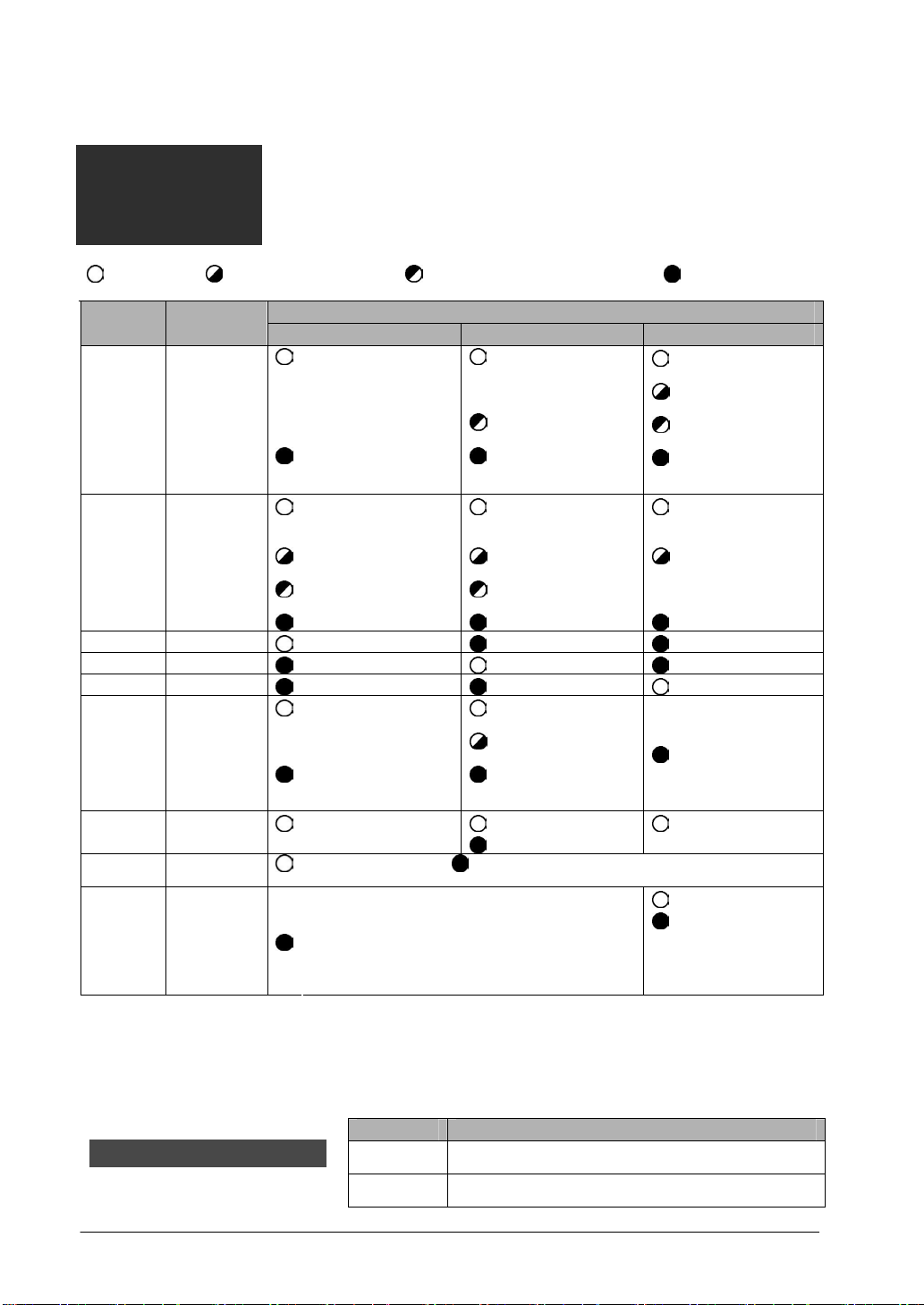
Operation monitor LEDs
:Lights:
:Flashing
:Flashing slowly (T = 1.0 s),
:Goes out:
(T = 0.2 s),
LED
COM.
ERR.
W
W2
F
PC-L
HI
TERM.
1/17~
8/24
9/25~16/
32
Descrip
tion
Communicati
on status
Hardware/
Software
error
W mode
W2 mode
F mode
PC link flag
(Available in
W/W2 mode
only)
Baud rate
Terminal
station
Slave station
display
(Availalbe in
F mode only)
Operation
W mode W2 mode F mode
:Communicating
(Normal)
:Communication error
(Transmission is not
available)
:Out of control/Selfdiagnostic
Error
:Wait for starting error
(Note1)
:Various errors
(Note2)
:Normal operation :Normal operation :Normal operation
:In W mode :Not in W mode :Not in W mode
:Not in W2 mode :In W2 mode :Not in W2 mode
:No in F mode :No in F mode :In F mode
:PC link operation
State
:PC link Operation
:PC link stop/
Non-PC link
operation State
:500 kbps fixed
:Communicating
(Normal)
:Communicating
:Communication
buffer Overload
:Communication
error (Transmission
is not available)
:Out of control/
Self-diagnostic
Error
:Wait for starting
error (Note1)
:Various errors
(Note2)
:PC link operation
state
impossible
:Non-PC link
operation State
:500 kbps
:250 kbps
:Waiting for
communication
(Normal)
:Stop mode
Transmitting
:Communication
error
:Out of control/
Self-diagnostic
Error
Setup error
:Not used
:500 kbps fixed
:Terminal station :Not terminal station
:Connected
:Not connected
:Not used
* Slave station numbers
are switched by the
slave station number
selector.
Note1) It occurs when the version of CPU unit is Ver. 1.05 or older.
Note2) It occurs in case of transmission errors, when a station number is out of range, station numbers
are duplicated, or allocated link areas are duplicated.
Station number selector
Swithces the display range of the station number display.It is used in the F mode only.
Item Setting
1-16 Indicates the monitor LEDs between the slave station
17-32 Indicates the monitor LEDs between the slave station
number 1 to 16.
number 17 to 32.
2-4

Station number selector
Sets the station number of the master unit in the W/W2 mode.It is not used in the F mode.
Operation Setting
01 to 32: Available
W mode
W2 mode
Point the arrow to the number to be used.
Mode selector switches
Operation
Setting SW
Operation
mode
Not used
station
setting
OFF PC link mode
1
ON Non-PC link mode
2 ― ―
3 ― ―
4 ― ―
5 ― ―
6 ― ―
7 7: ON, 8: ON Terminal station Terminal
8 7: OFF, 8: OFF Not terminal station
Other numbers: The station number setting error occurs.
(Changing station numbers in operation is possible.)
01 to 64: Available
Other numbers: The station number setting error occurs.
(Changing station numbers in operation is possible.)
W mode W2 mode F mode
The operation of the
master unit stops when
communication error
occurs.
The operation of the
master unit continues
when communication
error occurs.
W mode W2 mode F mode
1 OFF ON ON Operatio
The swithces are all
set to the OFF
position at the
factory.
n mode
rate
Note2)
― 4 Always set the switches to the OFF position.
Note1) The setting of the mode selector switches is reflected in the operation
monitor LEDs.
Note2) In the W2 mode, a unit at 500 kbps and a unit at 250 kbps cannot be
mixed in the same network.
Note3) Be sure the power is off when changing the selector position (except the
terminal station setting).
2 OFF OFF ON
OFF 500 kbps Baud
3
ON
500 kbps
fixed
250 kbps
500 kbps fixed
2-5

2.2 Remote I/O master unit
2.2.1 FP3 Remote I/O Master Unit (AFP3742)
Functions of each part
(1)Station number LEDs ………... The LEDs indicating the slave station numbers (No. 1 to
No. 32) which are connected to the network light up.
Check the lighting-up by swiching the display range of the
station number LEDs between number 1 to 16 and number
17 to 32 with "Station number selector".
(2)Operation monitor LEDs …... Indicates communication status and operation mode.
(3)Station number selector …...
Switches the display range of teh station number LEDs.
Refer to the description of "Station numbers LEDs" above.
2-6

(4)Mode selector switches
……
For selecting the transmission line, setting the terminal station and
selecting the mode when a tranmission error occurs.
SW Setting OFF ON
1、2 Port selection Port I Port I and Port II
Terminal station
3、4
5、6
7
setting
(Port I)
Terminal station
setting
(Port I)
Condition during a
communication error
* The settings of SW1 and SW2, SW3 and SW4, and SW5 and SW6
should be same.
* The swithces are all set to the OFF position at the factory.SW8 is
not used.
* The settings will be accepted when the power turns on.
Not terminal
station
Not terminal
station
Master Unit
Stop the operation
Terminal station
Terminal station
Master Unit
Continue the
operation
⑤RS485 interface …... For connecting the communication cables.Two poarts are available.
⑥Mounting screw ……
Connector
Connects the master unit to a slot on the backplane.
2-7
2.3 Remote I/O Slave Unit
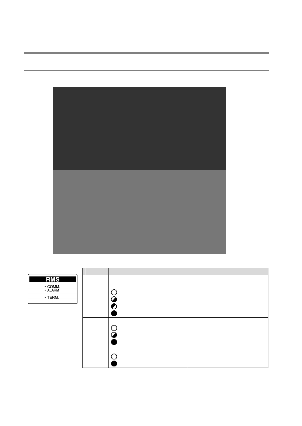
2.3.1 FP2 Remote I/O Slave Unit (AFP2745)
(1)Operation monitor LEDs
Name Display
COMM. Displays communication
TERM.
2-8
status.
: Lights
: Flashing (T = 0.2 s),
: Flashing slowly (T = 1.0 s),
: Goes out
Indicates an error on the unit. ALARM
: Lights
: Flashing quickly (T = 0.2 s),
: Goes out
Indicates the setting of termination resistance.
: Lights
: Goes out
: Waiting
: Communicating (Normal)
: Communicating (Stop mode)
: Communication error
: Unit error
: Setting error
: Normal operation
: Termination resistance is on.
: Termination resistance is off.
Switches
Note) Be sure the power is off when changing the switches.
(2)Station number selector
Sets the station number of teh remote I/O slave unit.
Setting
01 to 32: Available
Other numbers: The station number setting error occurs.
Note) Setting error: The ALARM LED blinks.
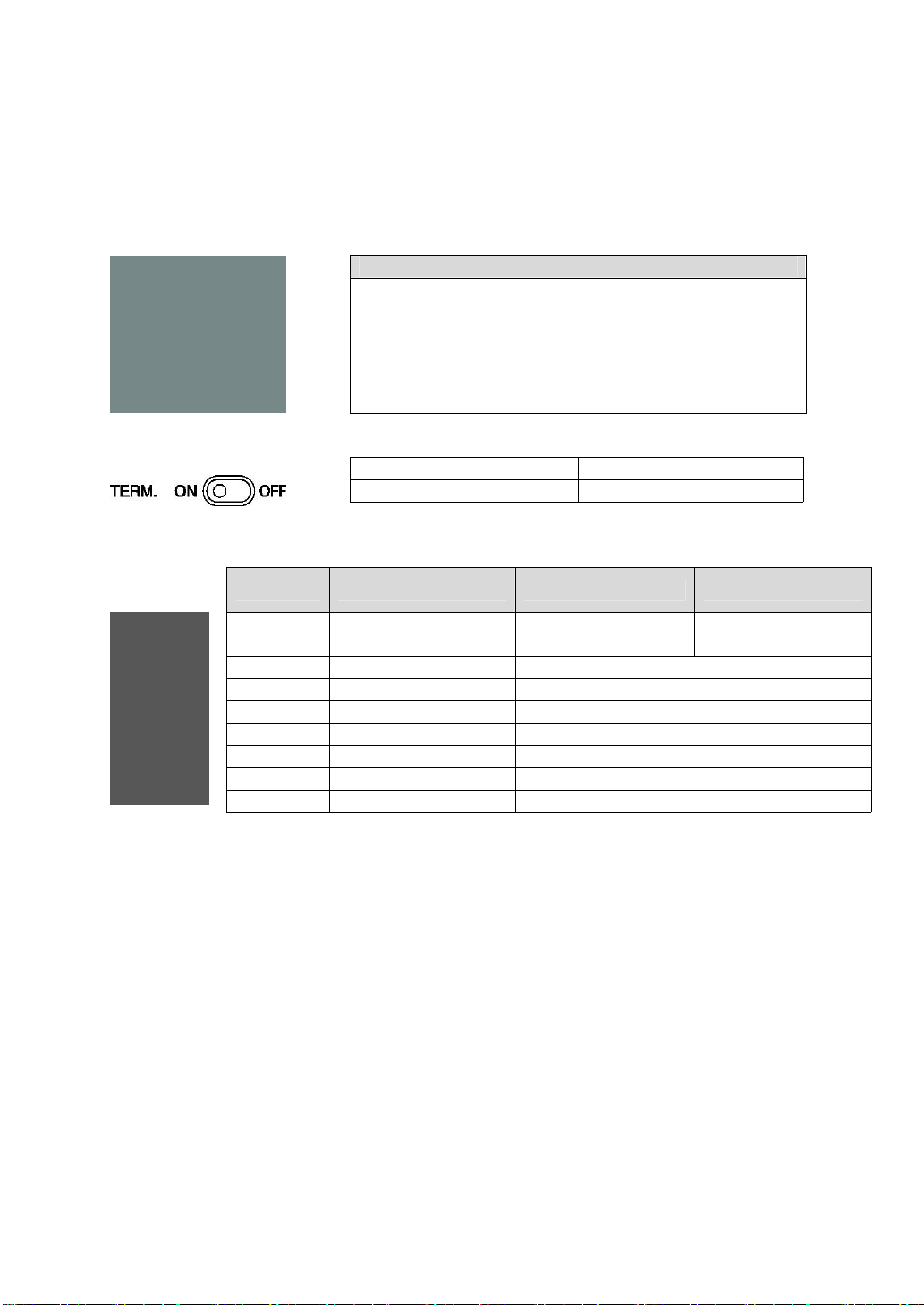
(3)Termination resistance selector switch
ON OFF
(4)Mode selector switches
SW No. Function ON OFF
Termination resistance: ON Termination resistance: OFF
1
2 Not used 3 Not used 4 Not used 5 Not used 6 Not used 7 Not used 8 Not used Note) Set the unused swithces to the off position.
(5)RS485 interface
(6)Fixing hooks
(7)Connector for connecting to a backplane
(8)Mounting screw
(9)Temporary joint hook
Output condition during
a communication error
Maintains its output
condition
Output off
2-9

2.3.2 FP3 Remote I/O Slave Unit (AFP3745)
Functions of each part
(1)Operation monitor LEDs …… Indicates communication status and operation mode.
(2)Station number selector switches.. Set the station number of the MEWNET-F.Point the arrow
to the number to be used. (Set tens place and ones place
separately.)
Setting range: 01 to 32
* When setting numbers exceeding the range, the setup
error occurs (ALARM LED flashes), and communication
becomes impossible.
* The settings will be accepted when the power turns on.
2-10

(3)Mode selector switches…. Sets the terminal station and the output mode a communication
error occurs.
SW Setting OFF ON
1、2 Terminal station setting
3
* The settings of SW1 and SW2 should be the same.
* The swithces are all set to the OFF position at the factory.SW4 is not
* The settings will be accepted when the power turns on.
Output condition during
a communication error
used.
Not terminal
station
Output off
Terminal station
Maintains its output
condition
(4)RS485 interface …... For connecting the communication cables.
(5)Mounting screw ……….
Connector
Connects the slave unit to a CPU slot on the backplane.
2-11

2.4 I/O Terminal Board
FP I/O terminal baord [MIL connector type]
(AFP87445, AFP87446)
FP I/O terminal baord [Terminal block type] (AFP87444, AFP87432)
2-12
 Loading...