

Panasonic MEW01 351, EBL512 G3 Planning Manual

Planning Instructions
MEW01351
Revision -
Fire Alarm System EBL512 G3
V1.1.x
Author: Jan Pettersson
Date of issue: 2011-02-11
Date of rev:

This page has deliberately been left blank.

Panasonic Electric Works Nordic AB
MEW01351 Rev: - Planning Instructions Fire alarm system EBL512 G3, V1.1.x
1
Table of contents
1 Introduction________________________________ 8
2 Definitions / Explanations ___________________ 10
2.1 PEWN AB _______________________________________ 10
2.2 Alarm points _____________________________________ 10
2.2.1 Smoke detector _______________________________ 10
2.2.2 Sensor ______________________________________ 10
2.2.3 Analog detector _______________________________ 10
2.2.4 Analog (Sensor) Base (ASB) ____________________ 10
2.2.5 Conventional detector __________________________ 10
2.2.6 (Conventional Detector) Base (CDB) ______________ 10
2.2.7 Addressable __________________________________ 10
2.2.8 Conventional zone line input / External line _________ 11
2.3 Output unit ______________________________________ 11
2.4 Output / Control output _____________________________ 11
2.5 Short circuit isolator (ISO) __________________________ 11
2.6 Display unit (D.U.) ________________________________ 11
2.7 COM loop _______________________________________ 11
2.8 Control Unit / C.U. / C.I.E. __________________________ 11
2.9 Fire Brigade Panel (FBP) ___________________________ 11
2.10 Control panel (CP) ________________________________ 11
2.11 System __________________________________________ 11
2.12 Network / TLON® / LonWorks® / Echelon / Node / TLON
Conn. board / Channel / Backbone net / Router / Repeater _______ 12
2.13 LED ____________________________________________ 12
2.14 External Indicator (Ext. LED) ________________________ 12
2.15 Display / LCD ____________________________________ 12
2.16 Door open (Door / Key switch) _______________________ 12
2.17 Site Specific Data (SSD) ____________________________ 13
2.18 Software (S/W) / System program ____________________ 13
3 Overview _________________________________ 14
3.1 The EBL512 G3 system ____________________________ 14
3.1.1 Printer ______________________________________ 14
3.1.2 Expansion boards _____________________________ 14
3.1.3 Power supply _________________________________ 14
3.2 S/W versions _____________________________________ 15
3.3 Documents ______________________________________ 15
3.4 Applications _____________________________________ 15
3.5 PC software (S/W) ________________________________ 15
3.5.1 WinG3 ______________________________________ 15
3.5.2 TLON Manager _______________________________ 16
3.5.3 WebG3 IConfig tool ___________________________ 16
4 Control Unit / TLON Network _______________ 17

Panasonic Electric Works Nordic AB
MEW01351 Rev: - Planning Instructions Fire alarm system EBL512 G3, V1.1.x
2
4.1 The TLON network ________________________________ 17
4.2 Single TLON Network / redundant TLON Network ______ 17
5 Control Units 5000 and 5001 _________________ 19
5.1 Mounting plates ___________________________________ 21
5.1.1 Mounting plate for 19" mounting rack, 5020 ________ 21
5.1.2 Mounting plate for inflammable wall, 5021 _________ 21
5.2 COM loops ______________________________________ 22
5.3 Programmable voltage outputs (S0-S3) ________________ 24
5.4 Programmable relay outputs (R0-R1) __________________ 24
5.5 Programmable inputs (I0-I3) _________________________ 24
5.6 Relay outputs for routing equipment (tx) _______________ 25
5.6.1 Fire alarm output ______________________________ 25
5.6.2 Fault condition output __________________________ 25
6 Expansion boards 458x _____________________ 26
6.1 Expansion board no. (address) setting __________________ 27
6.2 8 zones expansion board 4580 _______________________ 27
6.2.1 Type of zone line input _________________________ 28
6.2.2 Input states __________________________________ 28
6.3 8 relays expansion board 4581 _______________________ 29
6.4 Inputs and outputs expansion board 4583 _______________ 30
6.5 I/O Matrix board 4582 _____________________________ 31
6.5.1 Generic _____________________________________ 33
6.5.2 Fan control __________________________________ 33
6.5.3 Zone control _________________________________ 34
7 Printer ___________________________________ 35
8 TLON connection board 1590 ________________ 36
8.1 Single TLON Network _____________________________ 36
8.2 Redundant TLON network __________________________ 36
8.3 Network programming _____________________________ 36
9 Peripheral devices __________________________ 37
9.1 COM loop units ___________________________________ 37
9.1.1 Input units ___________________________________ 39
9.1.2 Addressable I/O units __________________________ 46
9.1.3 Alarm devices (addressable sounders) _____________ 48
9.1.4 Short circuit isolators (addressable) _______________ 49
9.1.5 Units for Hazardous (Ex) areas ___________________ 50
9.1.6 Other COM loop units __________________________ 51
9.1.7 COM loop addresses for Base station and Wireless
detectors 54
9.2 Units connected to the RS485 interface ________________ 54
9.2.1 External Fire Brigade Panels _____________________ 55
9.2.2 Alert Annunciation Units _______________________ 56
9.2.3 External Presentation Units ______________________ 57
9.2.4 German Fire Brigade Panels _____________________ 58
9.3 Units connected to the RS232 interface J7 ______________ 59

Panasonic Electric Works Nordic AB
MEW01351 Rev: - Planning Instructions Fire alarm system EBL512 G3, V1.1.x
3
9.3.1 Web-servers __________________________________ 59
9.4 Other units _______________________________________ 59
9.4.1 Alert Annunciation Controllers ___________________ 59
9.4.2 External LED ________________________________ 60
9.4.3 Alarm devices (sounders, etc.) ___________________ 60
9.4.4 Door release magnets __________________________ 60
9.4.5 Boxes _______________________________________ 61
9.4.6 Duct detector chambers _________________________ 61
10 Programmable inputs _______________________ 62
10.1 Control unit Inputs I0 - I3 & Inputs 0 -4 on exp. board 4583 63
10.1.1 Not supervised ________________________________ 63
10.1.2 Supervised ___________________________________ 63
10.2 The 3361 unit's Inputs In0 / Z & In1 ___________________ 63
11 Input programming ________________________ 64
11.1 Trigger conditions _________________________________ 64
11.2 Logic ___________________________________________ 67
11.2.1 Supervised ___________________________________ 67
12 Programmable outputs ______________________ 68
12.1 Control unit outputs S0 – S3 _________________________ 69
12.2 Control unit outputs R0 & R1 ________________________ 70
12.3 8 relays expansion board 4581 Output 0 – Output 7 _______ 70
12.4 Inputs and Outputs expansion board 4583 Output 0 & Output 170
12.5 The 3361 unit's Outputs Re0 & Re1 ___________________ 70
12.6 The 3364 unit's VO0 – VO2 _________________________ 71
12.7 The 3377 unit's Output (siren) ________________________ 71
12.8 The 3379 unit's Output (sounder) _____________________ 71
12.9 The 4380 unit's Output (beacon) ______________________ 71
13 Output programming _______________________ 72
13.1 Type of output ____________________________________ 72
13.2 Logic ___________________________________________ 73
13.3 Supervised / Not supervised _________________________ 73
13.4 Output signal period _______________________________ 73
13.5 Control expression ________________________________ 76
13.5.1 Trigger conditions _____________________________ 76
13.5.2 Logical operators ______________________________ 80
13.5.3 Control expression examples ____________________ 80
14 Interlocking function _______________________ 84
14.1 Programming of interlocking function _________________ 84
14.1.1 Interlocking output ____________________________ 84
14.1.2 Interlocking input _____________________________ 84
14.1.3 Interlocking combination _______________________ 84
14.2 Interlocking indications _____________________________ 86
14.3 Information of interlocking combinations (H9) __________ 86
14.3.1 Display interlocking information (H9/C1) __________ 86
14.3.2 Activate interlocking output (H9/C2) ______________ 87

Panasonic Electric Works Nordic AB
MEW01351 Rev: - Planning Instructions Fire alarm system EBL512 G3, V1.1.x
4
14.3.3 Reset interlocking output (H9/C3) ________________ 87
14.3.4 Disable interlocking output (H9/C4) _______________ 87
14.3.5 Re-enable interlocking output (H9/C5) _____________ 87
14.4 Interlocking control expressions ______________________ 87
15 Fire Door Closing __________________________ 88
16 Functions / Services / Features _______________ 89
16.1 Sensor value _____________________________________ 89
16.2 Week average sensor value __________________________ 89
16.3 Decision value ____________________________________ 90
16.4 Alarm algorithms for smoke detectors / Detection levels /
Offsets 90
16.4.1 Alarm algorithm / Alternative alarm algorithm ______ 91
16.4.2 Filtering algorithm ____________________________ 92
16.4.3 Smouldering smoke algorithm ___________________ 94
16.5 Performance factor ________________________________ 95
16.6 Algorithms for analog heat detectors __________________ 96
16.6.1 Class A1 algorithm ____________________________ 97
16.6.2 Class A2 S algorithm __________________________ 97
16.6.3 Class B S algorithm ____________________________ 97
16.7 Self verification ___________________________________ 98
16.8 Minimum / Maximum sensor values ___________________ 98
16.9 2-zone / 2-address dependence (Co-incidence alarm) ______ 99
16.9.1 2-zone dependence ____________________________ 99
16.9.2 2-address (-unit) dependence ___________________ 100
16.9.3 Reset of 2-zone / 2-address dependence (co-incidence
alarm 100
16.10 Delayed alarm _________________________________ 101
16.11 Alert Annunciation _____________________________ 102
16.12 Alarm Acknowledgement Facility (AAF) ____________ 104
16.13 Quiet alarm ___________________________________ 106
16.14 Fire alarm type A and Fire alarm type B _____________ 106
16.14.1 Fire alarm type B ___________________________ 107
16.14.2 Fire alarm type A __________________________ 107
16.15 Disable alarm points and outputs __________________ 107
16.15.1 Disable zone ______________________________ 108
16.15.2 Disable zone / address _______________________ 108
16.15.3 Disable control output _______________________ 108
16.15.4 Disable / Re-enable output type _______________ 108
16.15.5 Disable / Re-enable alarm devices _____________ 108
16.16 Disable interlocking output _______________________ 108
16.17 Disable outputs for routing equipment ______________ 108
16.18 Disconnect & Re-connect loop / zone line input _______ 109
16.19 External time channels 15-63 _____________________ 109
16.20 Test mode ____________________________________ 109
16.21 Test alarm devices ______________________________ 109

Panasonic Electric Works Nordic AB
MEW01351 Rev: - Planning Instructions Fire alarm system EBL512 G3, V1.1.x
5
16.22 Test of routing equipment ________________________ 110
16.23 Calibration of supervised outputs __________________ 110
16.24 Service signal _________________________________ 110
16.25 Fault signal (fault condition) ______________________ 111
16.26 Alarm texts ___________________________________ 111
16.26.1 Creating the alarm texts via WinG3 ____________ 111
16.26.2 Downloading alarm texts to the DU:s 1728 / 1735 /
1736 and ext. FBP:s 1826 / 1828 ________________________ 113
16.27 Real time clock (RTC) __________________________ 113
16.27.1 Daylight saving time ________________________ 114
16.28 Loss of main power source _______________________ 114
16.29 Evacuate _____________________________________ 114
16.30 WinG3 menu Tools _____________________________ 115
17 Special New Zealand functions ______________ 117
17.1 Alarm devices ___________________________________ 117
17.1.1 Silence alarm devices (inside switch) _____________ 117
17.1.2 New Zealand FB Silence switch (outside switch) ____ 117
17.2 Battery faults ____________________________________ 119
17.2.1 FAULT: Battery _____________________________ 119
17.2.2 FAULT: Low battery capacity __________________ 119
17.3 Watchdog reset __________________________________ 119
17.4 Routing equipment isolate (disable) __________________ 119
17.5 Acknowledged alarm _____________________________ 119
18 Cyber sensor functions _____________________ 121
18.1 Pulse up – down counter ___________________________ 122
18.1.1 Pulse up – down counter for smoke ______________ 122
18.1.2 Pulse up – down counter for temperature __________ 122
18.1.3 Pulse up – down counter for smoke & temperature __ 122
18.2 Fire judgement __________________________________ 122
18.3 Alarm threshold levels ____________________________ 123
18.4 Learning function / Learning conditions _______________ 123
18.4.1 Learning conditions ___________________________ 123
18.5 Alarm delay time _________________________________ 125
18.6 Analog data output _______________________________ 126
18.7 Sensitivity compensation __________________________ 126
18.8 Self diagnosis of internal devices ____________________ 127
18.9 Address setting check _____________________________ 127
19 Control unit properties ____________________ 128
19.1 Control unit properties dialog box ___________________ 128
19.1.1 General Information __________________________ 128
19.1.2 Peripherals __________________________________ 128
19.1.3 Misc. ______________________________________ 128
19.2 WinG3 Control unit pop-up menu ___________________ 129
19.2.1 Reset alarm counter ___________________________ 129
19.2.2 Software version _____________________________ 129

Panasonic Electric Works Nordic AB
MEW01351 Rev: - Planning Instructions Fire alarm system EBL512 G3, V1.1.x
6
19.2.3 Upgrade number of alarm points _________________ 129
19.2.4 Restart _____________________________________ 130
19.2.5 Delete _____________________________________ 130
19.2.6 Properties___________________________________ 130
20 System properties (settings) _________________ 131
20.1 System properties dialog box _______________________ 131
20.1.1 Name ______________________________________ 131
20.1.2 User definable text ___________________________ 131
20.1.3 System properties, Page 1 ______________________ 131
20.1.4 System properties, Page 2 ______________________ 133
20.2 Menu System ____________________________________ 134
20.2.1 Properties___________________________________ 134
20.2.2 Time channels _______________________________ 134
20.2.3 Alarm algorithms ____________________________ 136
20.2.4 Output Signal Periods _________________________ 138
20.2.5 National holidays ____________________________ 139
20.2.6 Two zone dependence _________________________ 140
20.2.7 Statistics (System information) __________________ 141
20.2.8 Edit Alarm texts _____________________________ 141
21 Compatibility_____________________________ 142
22 Cable types ______________________________ 143
22.1 TLON Network cables ____________________________ 143
22.2 COM loop cables_________________________________ 143
22.3 Ext. FBP / Display Units cables _____________________ 143
22.4 Conventional zone line cables _______________________ 143
22.5 Alarm device cables ______________________________ 144
22.6 Other cables _____________________________________ 144
23 COM loop cable length _____________________ 145
24 Current consumption ______________________ 148
25 Power supply _____________________________ 152
25.1 Charger functions ________________________________ 153
25.1.1 Charging ___________________________________ 153
25.1.2 Battery charging functions: _____________________ 153
25.1.3 Security functions ____________________________ 153
25.2 Current consumption calculations ____________________ 154
25.3 Rectifier (main power source) _______________________ 155
25.4 Battery (second power source) ______________________ 155
25.5 Fuses __________________________________________ 156
25.6 Form / Table of current consumption _________________ 156
26 S/W versions _____________________________ 158
27 Technical data ____________________________ 159
28 Limitations_______________________________ 160
28.1 User definable texts _______________________________ 160

Panasonic Electric Works Nordic AB
MEW01351 Rev: - Planning Instructions Fire alarm system EBL512 G3, V1.1.x
7
28.2 C.i.e. / System ___________________________________ 160
29 National regulations _______________________ 162
30 Drawings / connection diagrams _____________ 163
31 Revision history ___________________________ 164
Drawings according to the valid table of drawings.

Panasonic Electric Works Nordic AB
MEW01351 Rev: - Planning Instructions Fire alarm system EBL512 G3, V1.1.x
8
1 Introduction
EBL512 G3 Planning Instructions is a document1 intended to be used
by planning engineers as well as service / commissioning engineers.
This document should be read in conjunction with the drawings
according to the valid Table of drawings and the EBL512 G3
Operating Instructions MEW01163.
When planning a fire alarm installation the national regulations have
to be obeyed. A lot of detector types can be used. Detector coverage
area and detector placing in the room / building, etc. are matters for
the planning engineers and are not described in this document.
Due to continual development and improvement, different S/W
versions might be found. This document is valid for S/W version
1.1.x. On the date / revision date of the document x = 0.
Since the EBL512 G3 control unit (c.i.e.) is produced for many
countries the look, the texts, the functions, etc. might vary.
Products
Consists of one or more parts (HW) according to a Product Parts
List. A product has:
a type number
5000 EBL512 G3 c.i.e. Configured for 128, 256 or 512 alarm
points and with or without printer depending on article number.
5001 EBL512 G3 c.i.e. No front panel and no Plexiglas in the
door. Configured for 128, 256 or 512 alarm points depending
on the article number.
an article number is often the same as the type no. but a country
code can be added (e.g. SE for Sweden). If the letters PRT also
are added in the article number the product comes with a printer.
If digits are added to the article number they are showing the
number of alarm points configured (e.g. 5000PRTSE-128).
a product name (e.g. EBL512 G3 CU, 128 alarm points, with
printer)
HW
A HW (e.g. a printed circuit board) has:
a type number (e.g. 5010)
an article number, often the same as the type no. but sometimes a
country code is added (e.g. 5010SE)
1
File name: L:\Retailers\Panasonic Russia\Training 110223_25\EBL512
G3\Documents\MEW01351(Rev -).doc

Panasonic Electric Works Nordic AB
MEW01351 Rev: - Planning Instructions Fire alarm system EBL512 G3, V1.1.x
9
a product name (e.g. Main Board 128 alarm points)
a p.c.b. number (e.g. 9290-2B) and can also have a configuration
(e.g. CFG: 2) and a revision (e.g. REV: 1)
sometimes a S/W
S/W
A S/W has:
a version number (e.g. V1.1.x)
sometimes additional information, such as Convention (different
functions / facilities), Language, Number of addresses, etc.
PC S/W
A PC S/W is a program used for programming, commissioning, etc.
(e.g. WinG3). It has a version number (e.g. V1.1.x).

Panasonic Electric Works Nordic AB
MEW01351 Rev: - Planning Instructions Fire alarm system EBL512 G3, V1.1.x
10
2 Definitions / Explanations
Definitions / explanations / abbreviations / etc. frequently used or not
explained elsewhere in the document.
2.1 PEWN AB
Panasonic Electric Works Nordic AB
2.2 Alarm points
Units, which can generate a fire alarm (in the control unit), i.e. analog
detectors (sensors), conventional detectors, manual call points, etc.
2.2.1 Smoke detector
Analog and conventional photoelectric (optical) smoke detectors are
available.
2.2.2 Sensor
Sensor = Analog detector
2.2.3 Analog detector
Contains an A/D-converter. The Control Unit pick up the digital
values ("sensor values") for each detector individually. All
evaluations and "decisions" are then made in the c.i.e. Analog
detectors are addressable – an address setting tool is used for detector
types 430x.
An analog detector has to be plugged in an analog sensor base (ASB).
2.2.4 Analog (Sensor) Base (ASB)
An analog detector is plugged in an ASB, which is connected to a
COM loop (see below).
2.2.5 Conventional detector
Detector with only two statuses, i.e. normal and fire alarm. The
detector has a closing contact and a series alarm resistor. Normally
plugged in a conventional detector base CDB (see below) connected
to a conventional zone line input, with an end-of-line device. Some
types (e.g. water proof types) are connected directly on zone line.
2.2.6 (Conventional Detector) Base (CDB)
A conventional detector is plugged in a CDB, connected to a
conventional zone line input.
2.2.7 Addressable
A unit with a built-in address device, i.e. each unit is individually
identified, handled and indicated in the c.i.e.
(The unit can be an I/O unit with a zone line input, to which one or
more conventional "alarm points" can be connected.)

Panasonic Electric Works Nordic AB
MEW01351 Rev: - Planning Instructions Fire alarm system EBL512 G3, V1.1.x
11
2.2.8 Conventional zone line input / External line
Input intended for one or more conventional alarm points. End-of-line
device in the last alarm point on the line.
2.3 Output unit
Addressable unit with programmable control outputs. Connected to a
COM loop (see below).
2.4 Output / Control output
Defined or programmable function. Relay output or voltage output
(supervised / monitored or not), in the c.i.e. or an output unit
connected on a COM loop.
2.5 Short circuit isolator (ISO)
Addressable unit for automatic disconnection of a part (segment) of a
COM loop (see below) in case of short circuit on the loop.
(According to EN54-2, one ISO is required per 32 alarm points.)
2.6 Display unit (D.U.)
Addressable unit for fire alarm presentation (incl. user definable alarm
text messages, if programmed).
2.7 COM loop
Loop = a cable, with two wires, to which all the addressable units can
be connected. Starts in the c.i.e. and it returns back to the c.i.e.
2.8 Control Unit / C.U. / C.I.E.
Control Unit = Control and Indicating Equipment = Unit to which the
alarm points are connected (via e.g. a COM loop). Indicates fire
alarm, fault condition, etc. Fire Brigade Panel & Control Panel, i.e.
the front, included or not included. Printer included or not included.
2.9 Fire Brigade Panel (FBP)
Unit intended for fire alarm presentation, etc. for the fire brigade
personnel. Can be a part of the control unit (a part of the front) or a
separate unit (external FBP).
In the ext. FBP, a printer can be included or not included.
2.10 Control panel (CP)
A part of the control unit (a part of the front), intended for the building
occupier, service personnel, etc., to "communicate" with the control
unit / system.
2.11 System
One control unit or several control units connected via a TLON
network (co-operating control units).

Panasonic Electric Works Nordic AB
MEW01351 Rev: - Planning Instructions Fire alarm system EBL512 G3, V1.1.x
12
2.12 Network / TLON® / LonWorks® / Echelon /
Node / TLON Conn. board / Channel /
Backbone net / Router / Repeater
Brief explanations to the words/expressions to be found in connection
with a "network". See also separate TLON Technical description.
TLON® = TeleLarm Local Operating Network = a LonWorks®- based
network2 for communication between several units/nodes. The
protocol is called LonTalk and the transmission works with doublyterminated bus topology (Echelon FTT-10). To connect a control unit
to the network, a TLON connection board has to be plugged in the
control unit. EBL512 G3 also supports redundant TLON system
communication. In this case two TLON connection boards have to be
plugged in each control unit.
A network can be one channel (FTT-10) or several channels,
connected via routers. (In the TLON Network a sub net = a channel.)
Routers are also used to increase the maximum cable length, node to
node, in a network.
Router or Repeater is the same type of unit (different configuration).
All network programming (configuration) are made with the PC
program "TLON Manager".
2.13 LED
LED (Light Emitting Diode) = Yellow, green or red optical indicator
("lamp").
2.14 External Indicator (Ext. LED)
A unit with an LED. Connected to an ASB, CDB or any detector with
an output for an ext. LED. (In old installations also an ADB.)
Lit when the built-in LED in the detector / base is lit.
2.15 Display / LCD
LCD (Liquid Crystal Display) = Display (in the c.i.e. or Display unit)
for presentation of fire alarms, fault messages, etc. In EBL512 G3 it
is a graphical monochrome LCD (320 x 240 dots) with backlight.
2.16 Door open (Door / Key switch)
In EBL512 G3 there is a door switch, which is activated when the
control unit's door is open. In the ext. FBP 1828 this door switch is
replaced with a key switch.
An open door is indicated in the LCD (i.e. an "open door" icon).
2
LonWorks® = A "summing-up-name" for the market of Echelon
Corporation Inc. technology.

Panasonic Electric Works Nordic AB
MEW01351 Rev: - Planning Instructions Fire alarm system EBL512 G3, V1.1.x
13
2.17 Site Specific Data (SSD)
The SSD is unique for each installation. All alarm points,
presentation numbers, user definable alarm text messages,
programmable outputs, etc. are created in the PC program WinG3 and
also downloaded in EBL512 G3 with WinG3.
2.18 Software (S/W) / System program
The S/W (firmware) makes the control unit (the microprocessor)
work. It is factory downloaded but a new version can, via the PC
program WinG3, be downloaded in EBL512 G3 on site.

Panasonic Electric Works Nordic AB
MEW01351 Rev: - Planning Instructions Fire alarm system EBL512 G3, V1.1.x
14
3 Overview
3.1 The EBL512 G3 system
EBL512 G3 is a microprocessor controlled intelligent fire alarm
system, intended for analog addressable smoke detectors, as well as
conventional detectors and manual call points. Programmable control
outputs and output units are available. Up to 1020 addresses (of
which up to 512 can be alarm points) can be connected to each control
unit (c.i.e.) - according to EN54-2.
EBL512 G3 is available in several types, versions and configurations.
It can be connected to a TLON network, i.e. in a "system" with up to
30 control units. Each control unit has access to all information.
Product type no.
Product name
5000
EBL512 G3 c.i.e. With or without a printer.
With front and display.
5001
EBL512 G3 c.i.e.
Without front, display and printer. No door.
EBL512 G3 is designed according to the European standard EN54,
part 2 and 4. The Swedish front conforms to SS3654.
3.1.1 Printer
The control unit EBL512 G3 type 5000 can be delivered with a printer
("PRN" included in the article number) or without a printer.3
In Ext. Fire Brigade Panel 1826 it is possible to mount an optional
Printer 1535.
3.1.2 Expansion boards
In the control unit (c.i.e.) it is possible to mount up to six expansion
boards. The following types are available:
Product type no.
Product name
Note
4580
8 zones expansion board
4581
8 relay outputs expansion board
4583
In- and outputs expansion board
Regarding the expansion boards, see also chapter "Expansion boards
458x, page 26 and EBL512 G3 drawings.
3.1.3 Power supply
The main power source is a built-in switched power supply (rectifier)
5037. 230 V AC, 1.6 A / 24 V DC, 6.5 A.
The second power source is a backup battery (2 x 12 V). In the c.i.e.
3
Printer 5058 is a spare part for the c.i.e. type 5000 with a printer, i.e. it
comes without a mounting frame etc.

Panasonic Electric Works Nordic AB
MEW01351 Rev: - Planning Instructions Fire alarm system EBL512 G3, V1.1.x
15
is space for two 28 Ah batteries. Larger batteries (up to 65 Ah) have
to be placed outside the c.i.e.
The batteries and the power supply are connected to the Main board
(5010), which handles the charging of the batteries, etc. See chapter
"Power supply", page 152 for more information.
3.2 S/W versions
Due to continual development and improvement, different S/W
versions can be found. When installing a new control unit in a system
with "older" control units, you might have to update the S/W in the
old control units (or download an older version in the new control
unit). The same S/W version is required in all control units in a
TLON network.
3.3 Documents
The following documents are available:
Planning Instructions
Operating Instructions MEW01163
Drawings
Normally, information found in one of the documents is not found in
another document, i.e. the documents complement each other.
3.4 Applications
The EBL512 G3 system is intended for small, medium and large
installations. The intelligent control units offer the system designer
and end user a technically sophisticated range of facilities and
functions. Programming (PC software WinG3 and TLON Manager)
and commissioning of the control units / system is very easy.
Start with one control unit and then later when it is required, add more
units. The TLON network makes it possible to install the control units
in one building or in many buildings.
3.5 PC software (S/W)
The following PC software is used together with the EBL512 G3
system.
3.5.1 WinG3
WinG3 is used for programming and commissioning of one or more
control units, i.e. to:
create and download / make a backup of site specific data (SSD)
download new software / settings / conventions / configurations /
control unit & system properties / etc.
create and download the user definable alarm text messages
shown in the display in the control units / ext. FBPs and other
Display Units.

Panasonic Electric Works Nordic AB
MEW01351 Rev: - Planning Instructions Fire alarm system EBL512 G3, V1.1.x
16
WinG3 shall have the same version number as the EBL512 G3
software version number, e.g. 1.1.x and 1.1.x respectively. (x
indicates only a small correction and is not required to be the same.)
Old SSD files can be opened in a newer (higher) version of WinG3,
saved, edited and thereafter downloaded to an EBL512 G3 with the
corresponding version.
3.5.2 TLON Manager
TLON Manager is used for the TLON Network programming, i.e
data / addresses / etc.
3.5.3 WebG3 IConfig tool
A PC tool, WebG3 Config tool is used for configuration of the Webserver II (1598).

Panasonic Electric Works Nordic AB
MEW01351 Rev: - Planning Instructions Fire alarm system EBL512 G3, V1.1.x
17
4 Control Unit / TLON Network
4.1 The TLON network
An installation (a system) can be one control unit (c.i.e.) or up to 30
control units connected in a TLON Network.
In a TLON Network each control unit works independent but has
nevertheless total access to all information in the system.
NOTE!
In a system with two or more control units in a TLON Network, pay
attention to the following:
A zone must not be distributed over the system, i.e. all alarm
points in a zone have to be connected to one c.i.e.
When the "Fire door closing" function is used, the alarm points
and their "belonging" output must be connected to the same c.i.e.
When the interlocking function is used, the input, the output and
the Interlocking Combination (area-point) must be in / connected
to one c.i.e. An input and an output can only be used in one
Interlocking combination.
When the AAF function is used, all devices within the same AAF
zone must be connected to the same c.i.e.
4.2 Single TLON Network / redundant TLON
Network
The EBL512 G3 system can be build up as a single TLON Network or
a redundant TLON Network.
In the single TLON Network, one TLON connection board (1590) has
to be plugged in each control unit whereas in the redundant TLON
Network, two TLON connection boards have to be plugged in each
control unit.
In the single TLON Network, only one network is available (Network
no. 0) but in the redundant TLON Network, two networks are
available (Network no. 0 and Network no. 1).
The redundant TLON Network supports full functionality also in case
of a network fault (i.e. open circuit or short circuit) in one of the
TLON networks. A fault in one of the TLON Networks generates the
following fault:
FAULT: Control unit xx has no contact
with control unit xx, network x
Where network x = Network no. 0 or Network no. 1.

Panasonic Electric Works Nordic AB
MEW01351 Rev: - Planning Instructions Fire alarm system EBL512 G3, V1.1.x
18
NOTE!
In a system where each control unit is independent of the other (i.e.
each control unit works like a "standalone" control unit) a single
TLON Network may be sufficient. To maintain security, in this case:
All control units shall be of type 5000, i.e. including front panel.
The alarm points and their "belonging" outputs shall be connected
to the same control unit.
If fire alarm routing equipment (Fire brigade tx) shall be used,
each control unit in the system shall be able to activate a fire
alarm routing equipment independent of the other control units.
In all other cases and for highest security, a redundant TLON Network
shall be used.
(According to EN54-13, 4.3.1.2: A single fault on a transmission
path connecting one CIE to another CIE, shall not adversely affect the
correct functioning of any part of the networked system.)
Panasonic Electric Works Nordic AB
MEW01351 Rev: - Planning Instructions Fire alarm system EBL512 G3, V1.1.x
19
5 Control Units 5000 and 5001
Two types of control units are available:
Type no.
Product
Front
(FBP with
display & CP)
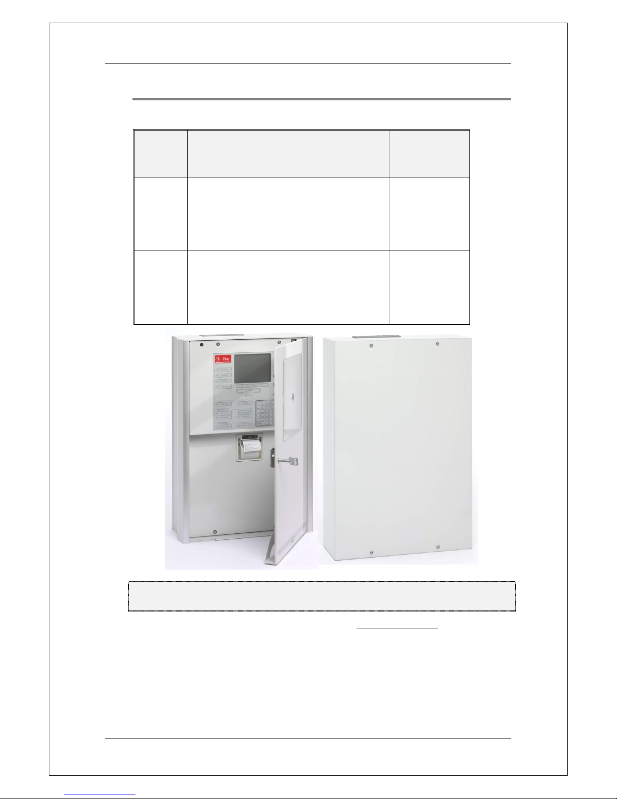
5000
EBL512 G3 c.i.e.
Expansion boards can be mounted (option).
Configured for 128, 256 or 512 alarm points
and with or without printer is depending on
the article number.
Yes
5001
EBL512 G3 c.i.e.
Expansion boards can be mounted (option).
Configured for 128, 256 or 512 alarm points
depending on the article number.
Printer cannot be mounted.
No
Figure 1. Left: The EBL512 G3 Control Unit 5000, with printer. The look might
vary according to configuration, etc. Right: The EBL512 G3 Control Unit 5001.
The control unit is housed in a grey metal cabinet. Depending on
country, convention, configuration, etc. the look, language and
functions might vary, as well as the max. number of alarm points
(128, 256 or 512). In total, 1020 COM loop units (addresses) can
always be used.
The door in type 5000 has a Plexiglas ahead of the front, see Figure 1
and Figure 2 respectively.
Panasonic Electric Works Nordic AB
MEW01351 Rev: - Planning Instructions Fire alarm system EBL512 G3, V1.1.x
20
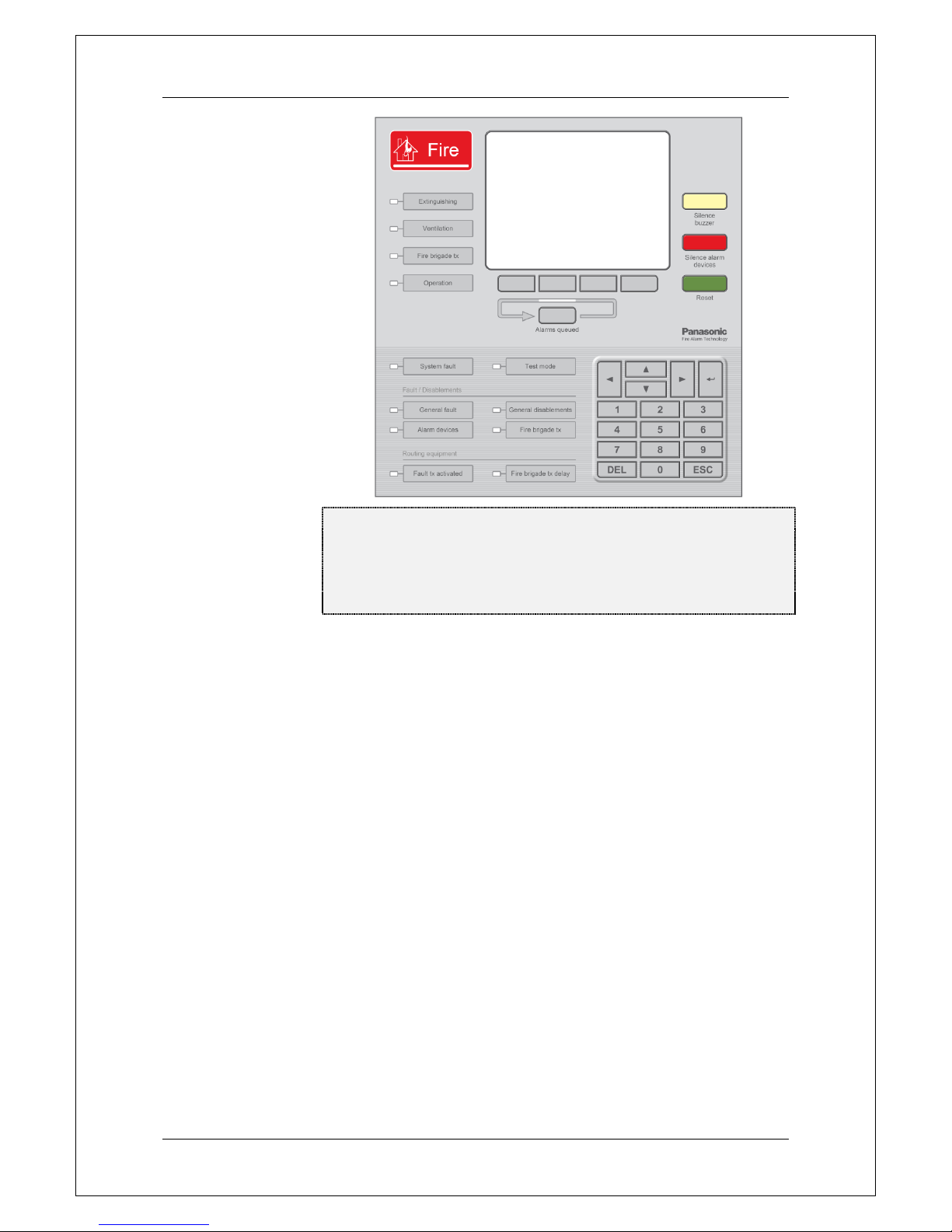
Figure 2. The EBL512 G3 front with display ("Man-Machine-
Interface"); The Fire Brigade Panel (FBP) is the upper part and
the Control Panel (CP) is the lower part. The look might vary
depending on the language, country, etc. (A front with texts in
English is shown in the figure).
The FBP is used by the fire brigade personnel to see which alarm
point(s) / zone(s) having activated fire alarm and to take required
operational control of the system. In the graphical display, the
information displayed in the upper part is depending on how many
alarm points / zones having activated fire alarm. In the middle part
will the fire alarms be shown, i.e. one alarm point or one zone together
with a user definable alarm text (if programmed) plus some other
information.
External FBPs are also available.
The CP is to "communicate" with the system, i.e. for commissioning,
monthly tests, maintenance, etc. Access codes for different access
levels are required. A keypad is used to get access to the system (a
menu tree with main and sub menus) and for operational control of the
system. The CP has several system status LEDs.
NOTE! Regarding LED indicators, keypad / push buttons / soft keys,
access levels and for more information, see EBL512 G3 Operating
Instructions MEW01163.

Panasonic Electric Works Nordic AB
MEW01351 Rev: - Planning Instructions Fire alarm system EBL512 G3, V1.1.x
21
Each control unit 5000-5001 has the following basic configuration:
Grey metal cabinet
MMI board (5011) (not in 5001)
EBL512 G3 front with display (not in 5001)
Main board (5010)
Space & connectors for two TLON connection boards (1590).
Four COM loops (0-3) to which the loop units are connected.
Four programmable supervised voltage outputs (S0-S3).
Two programmable relay outputs (R0-R1).
Four programmable inputs (I0-I3).
Six 24 V DC outputs (power supply outputs for Web-server II
(1598), routing equipment and external equipment).
Connections and more information, see dwg. 512 G3 - 22.
Two not programmable relay outputs for routing equipment
(Fire alarm output for Fire brigade tx and Fault condition
output for Fault tx). Connections and more information, see
dwg. 512 G3 - 24.
Battery charger.
Built-in power supply. See chapter "Power supply", page 152.
Connections and more information, see dwg. 512 G3 - 21.
Switched power supply (rectifier), 230 V AC / 24 V DC
(5037).
Space and connection cables for two Sealed Lead-Acid backup
batteries (12 V, 28 Ah).
Space for up to six expansion boards (458x).
See following chapters for more and detailed information.
5.1 Mounting plates
The 5000 and 5001 units are delivered with a mounting plate
approved for mounting on an incombustible wall (e.g. concrete).
5.1.1 Mounting plate for 19" mounting rack, 5020
When the 5000 and 5001 units shall be mounted in a 19" mounting
rack, the standard mounting plate can be replaced with a Mounting
plate for 19" mounting rack 5020.
5.1.2 Mounting plate for inflammable wall, 5021
When the 5000 and 5001 units shall be mounted on an inflammable
wall (e.g. wood), the standard mounting plate should be replaced with
a Mounting plate for inflammable wall 5021, which can be provided
with cable glands.

Panasonic Electric Works Nordic AB
MEW01351 Rev: - Planning Instructions Fire alarm system EBL512 G3, V1.1.x
22
5.2 COM loops
Each control unit has four COM loops (0-3) to which the loop units
are connected. Connections according to dwg 512 G3 – 25, - 31, - 36,
- 37 & - 38.
On each COM loop can up to 255 COM loop units be connected
(COM loop address 001 – 255). Regarding type and number of COM
loop units in relation to the cable length / type, see dwg 512 G3 – 41
and chapters "COM loop cable length", page 145 and "Current
consumption", page 148.
NOTE! In total, up to 1020 (4 x 255) COM loop units can be used
but only 512 can be alarm points, according to EN54-2.
Each COM loop unit has a COM loop address (e.g. 123) and
depending on the loop number (e.g. 0) and the control unit number
(e.g. 04) each COM loop unit gets a technical number (04 0 123).
Each alarm point and zone line input has a fire alarm presentation
number (Zone-Address), e.g. 001-01. See EBL512 G3 Operating
Instructions MEW01163 for more information.
Break or short circuit on a COM loop
Normally the control unit communicates with the COM loop units in
the A-direction only. In the B-direction is only the COM loop voltage
checked, in order to find a break on the loop.
A break or short circuit on a COM loop will generate a fault in the
control unit within 60-100 seconds (EN54-2 requirement).
A single break (cut-off) on a COM loop (open circuit).
The following will happen:
Since not all COM loop units are found by the control unit, the
communication starts in the B-direction also.
Since it is a single break, all units will now be found by the
control unit. A fault will be generated and a fault message will be
shown in the display:
FAULT: Cut-off loop x, control unit xxSCI nn
<-> SCI nn
NOTE! nn = A, 00, 01, 02, 03, 04, 05, 06, 07, 08, 09, 10, 11, 12,
13, 14, 15 or B.
Each 10th minute a new attempt is made to communicate in the
A-direction only, i.e. when the break is repaired / corrected, the
communication starts again in the A-direction only, within 10
minutes.
Regarding Fault acknowledge, see the EBL512 G3 Operating
Instructions MEW01163.
Two or more breaks on a COM loop.
The following will happen:

Panasonic Electric Works Nordic AB
MEW01351 Rev: - Planning Instructions Fire alarm system EBL512 G3, V1.1.x
23
Since not all COM loop units are found by the control unit, the
communication starts in the B-direction also.
Since it is not a single break, all units will not be found by the
control unit. A fault will be generated for each unit not found and
one or more fault messages will be shown in the display:
FAULT: No reply xxx-xx
Technical number xxxxxx
Each 10th minute a new attempt is made to communicate in the A-
direction only. When the breaks are repaired / corrected, the
communication starts again in the A- direction only, within 10
minutes.
Regarding Fault acknowledge, see the EBL512 G3 Operating
Instructions MEW01163.
Short circuit on a COM loop
The following will happen:
Since the COM loop current will be too high, the communication
will be stopped and the COM loop will be disabled.
A fault will be generated and a fault message shown in the
display:
FAULT: Short-circuit SCI nn <-> SCI nn,loop
x, control unit xx
NOTE! nn = A, 00, 01, 02, 03, 04, 05, 06, 07, 08, 09, 10, 11, 12,
13, 14, 15 or B.
Each 10th minute a new attempt is made to re-enable the COM
loop. When the short circuit is repaired / corrected, the
communication starts again in the A-direction only, within 10
minutes.
Regarding Fault acknowledge, see the EBL512 G3 Operating
Instructions MEW01163.
NOTE! If one or more Addressable short circuit isolators (4313) are
used4, the loop will be divided into "segments" (i.e. the part between
two short circuit isolators or between the control unit and one short
circuit isolator). Only the affected segment will be isolated, which
will minimise the number of units disabled by a short circuit.
The fault messages will also show between which isolators the short
circuit or the double breaks are situated, e.g.:
FAULT: Short-circuit SCI 02 <-> SCI 03, loop
0, control unit 00
If no addressable short circuit isolator (4313) is used, the whole COM
loop will be disabled and the fault message will be (e.g.):
FAULT: Short-circuit SCI A <-> SCI B, loop 0,
control unit 00
4
One short circuit isolator per 32 alarm points is required according to
EN54-2.

Panasonic Electric Works Nordic AB
MEW01351 Rev: - Planning Instructions Fire alarm system EBL512 G3, V1.1.x
24
5.3 Programmable voltage outputs (S0-S3)
The 24 V DC outputs S0-S3 are supervised (monitored)5.
Connections according to dwg 512 G3 – 23. When all connections are
done a calibration has to be performed, see chapter "Calibration of
supervised outputs", page 110 and the EBL512 G3 Operating
Instructions MEW01163, chapter "Calibration of supervised outputs
(menu H5/A1)".
Each output has to be programmed (via WinG3) regarding:
Type of output, i.e. output for Control, Alarm devices, etc.
Logic, i.e. normally low (default) or normally high (24 V DC)6.
Activation time and type (steady, pulse, delay, etc.).
Control expression (one or more trigger conditions).
See also the WinG3 help and chapter "Programmable outputs", page
68.
5.4 Programmable relay outputs (R0-R1)
Connections according to dwg 512 G3 – 23.
Each output has to be programmed (via WinG3) regarding:
Type of output, i.e. output for Control, Alarm devices, etc.
Logic, i.e. normally open (NO) or normally closed (NC) contacts.
Activation time and type (steady, pulse, delay, etc.).
Control expression (one or more trigger conditions).
See also the WinG3 help and chapter "Programmable outputs", page
68.
5.5 Programmable inputs (I0-I3)
Connections according to dwg 512 G3 – 23.
Each input has to be programmed (via WinG3) regarding:
Trigger condition (Triggered by).
Logic, i.e. normally open (NO) or normally closed (NC) contacts.
Additional information, depending on the selected trigger
condition (Fault no., Zone, Address, Fault message (Error text),
etc.)
Open = R > 2K. Closed 0 R < 2K.
An input has to be activated > 0.5 sec.
See also the WinG3 help and chapter "Programmable inputs", page
62.
5
The outputs are in WinG3 default set as supervised but via WinG3 it is
possible to set each output (S0-S3) individually to be not supervised.
6
A normally high output is not supervised.

Panasonic Electric Works Nordic AB
MEW01351 Rev: - Planning Instructions Fire alarm system EBL512 G3, V1.1.x
25
5.6 Relay outputs for routing equipment (tx)
Not programmable outputs. The outputs can be tested via menu H1,
see the EBL512 G3 Operating Instructions MEW01163. Connections
according to dwg 512 G3 – 24.
5.6.1 Fire alarm output
This output is normally used for fire alarm routing equipment (Fire
brigade tx). It is a change-over relay contact that will be activated
when a fire alarm is generated in the system7. Activated output is
(normally) indicated by the LED "Fire brigade tx".8
5.6.2 Fault condition output
This output is normally used for fault warning routing equipment
(Fault tx). It is a change-over relay contact that is normally activated
and will be de-activated in case of a fault9 in the control unit (c.i.e.)10.
De-activated output (i.e. fault condition) is indicated by the LED
Routing equipment "Fault tx activated".
7
The output can be disabled via "door open" or via menu H2/B9. See also
chapter "Alert Annunciation", page 100.
8
This output and programmable outputs with type of output = Fire brigade
tx, will normally turn on the LED but a programmable input with trigger
condition = Activated routing equipment, can turn on the LED instead.
9
Also when the control unit is out of power (i.e. power supply and battery
out of work) or Watch-dog fault.
10
The output can be disabled via "door open" or via menu H2/B9.
Panasonic Electric Works Nordic AB
MEW01351 Rev: - Planning Instructions Fire alarm system EBL512 G3, V1.1.x
26
6 Expansion boards 458x
Inside EBL512 G3 (5000 and 5001) there are space and holders for up
to six optional expansion boards of the types 4580, 4581 and 4583 to
be mounted, see drawing 512 G3 - 01. A ribbon cable 5089 shall be
used for connection of up to six expansion board(s) to the main board.
(Connector "J2" on the expansion board respectively and "J9" on the
main board 5010.) See drawing 512 G3 - 26.
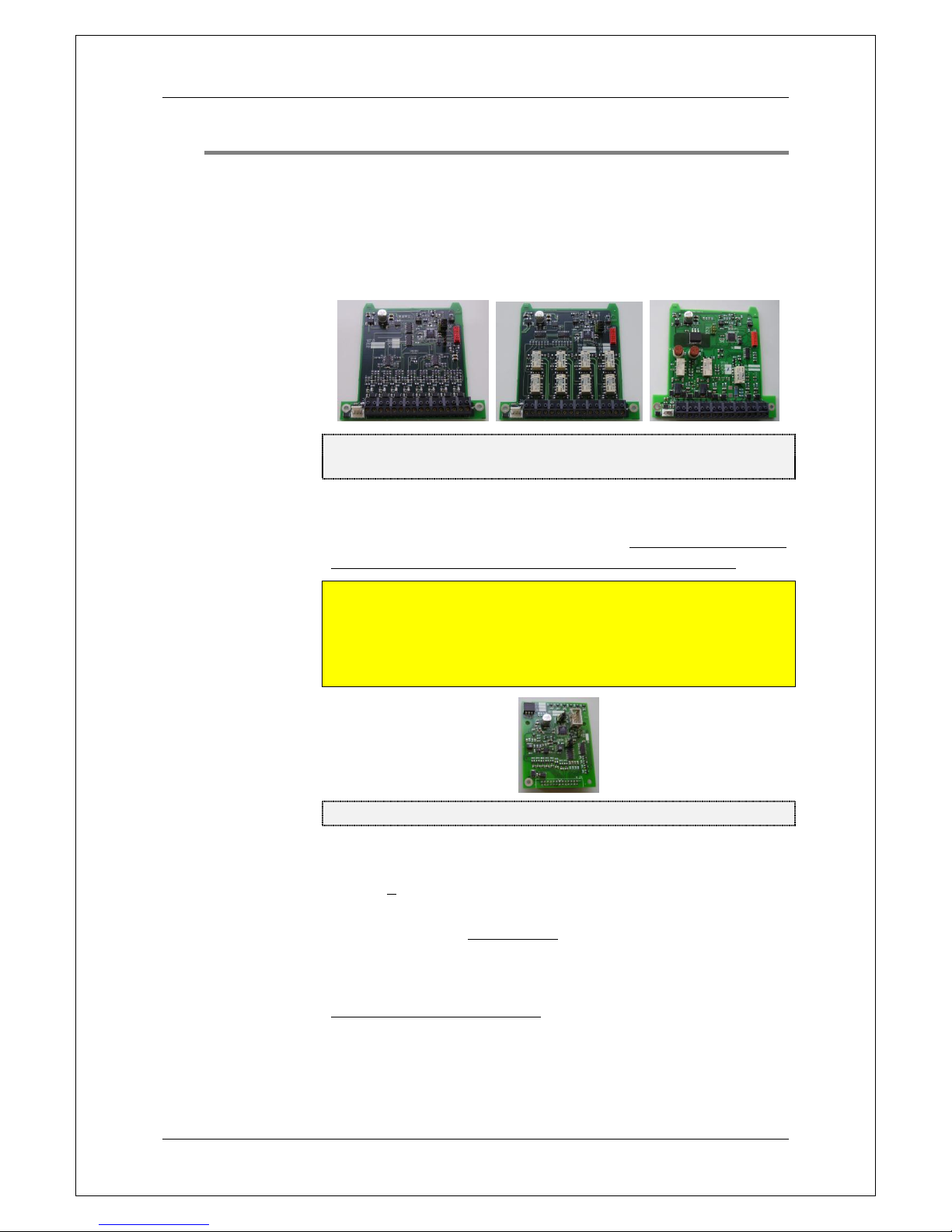
Figure 3. 8 zones expansion board 4580, 8 relays expansion
board 4581 and In- and outputs expansion board 4583.
I/O Matrix board 458211 is a special type of "expansion board",
plugged as a "piggy back" to an Application board11, which is
connected to a COM loop and to 24 V DC. On each COM loop 0-3
can up to six 4582 boards be used (i.e. up to 24 boards in total).
NOTE! COM loop 0 is however a special loop, since the exp. boards
4580, 4581 and 4583 actually are internally connected on this loop,
i.e. on COM loop 0 can in total up to six 4580, 4581, 4583 and 4582
boards be used. This means that for each exp. board 4580, 4581 and
4583 used, the number of 4582 boards is reduced with one.
Figure 4. I/O Matrix board 4582.
Max. six of the I/O Matrix boards 4582 can be programmed as type
Generic and/or Zone control.
NOTE! < 200 programmable outputs per c.i.e. can be used.
Each expansion board 4580, 4581 & 4583 and the I/O Matrix board
4582 have to have a board address (board no. 0-5) set via jumpers on
the board respectively. On boards of type 4580, 4581 and 4583
jumpers "JP2-JP4" and on board type 4582 jumpers "JP1-JP3", see
Figure 5, page 27. All the board programming is done via WinG3.
11
The 4582 board can be programmed as type Fan, Generic or Zone control.
It is mostly used with Australian Application boards but the General I/O
application board 4596 and Fan control application board 4594 (used with the
Fan control panel 4593) are available on all markets, see page 51.
Panasonic Electric Works Nordic AB
MEW01351 Rev: - Planning Instructions Fire alarm system EBL512 G3, V1.1.x
27
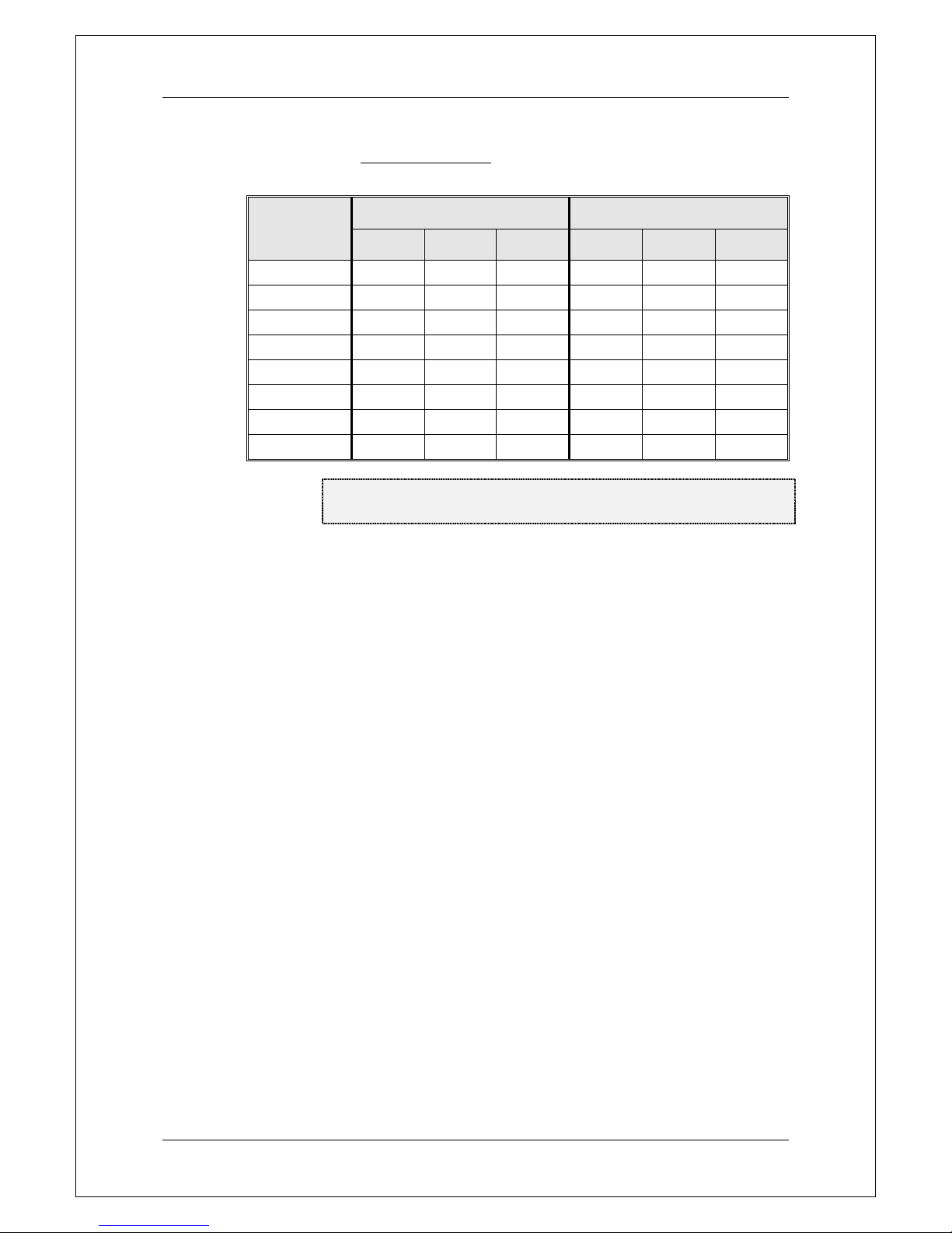
6.1 Expansion board no. (address) setting
The expansion board no. (address) is set via jumpers on the expansion
board respectively.
Board no.
(address)
4580, 4581 and 4583
4582
JP2
JP3
JP4
JP1
JP2
JP3
0
Open
Open
Open
Open
Open
Open
1
Shunted
Open
Open
Shunted
Open
Open
2
Open
Shunted
Open
Open
Shunted
Open
3
Shunted
Shunted
Open
Shunted
Shunted
Open
4
Open
Open
Shunted
Open
Open
Shunted
5
Shunted
Open
Shunted
Shunted
Open
Shunted
Figure 5. Expansion boards 4580 - 4583. Jumpers for
expansion board no. (address) setting.
6.2 8 zones expansion board 4580
Each board has to be programmed via WinG3 regarding:
Address / Board no. (set via the jumpers "JP2-JP4", see Figure 5
above.)
The 4580 board has eight conventional zone line inputs (0-7) intended
for conventional detectors. In the last alarm point on each zone line,
has to be connected an end-of-line device, depending on the selected
"Type of zone line input", see below.
Connections to "J1:1-16" and "J2" according to drawing 512 G3 - 33.
Each zone line input has to be programmed via WinG3 regarding:
Type of zone line input (see below), depending on detectors / end-
of-line device (capacitor or resistor), i.e. different threshold levels
etc.
Alarm at short circuit / No alarm at short circuit (i.e. if short-
circuit on the zone line shall generate a fire alarm or a fault)
Zone number (no address)
Fire alarm delay / No fire alarm delay
Text (Alarm text – if you wish)
Alert annunciation & time channel
Disablement & time channel
For more information, see the WinG3 help.
The terminals support a wire size up to 1.13 mm2 (1.2 mm).

Panasonic Electric Works Nordic AB
MEW01351 Rev: - Planning Instructions Fire alarm system EBL512 G3, V1.1.x
28
6.2.1 Type of zone line input
Each input shall be selected as Not used or one of the following types
/ modes.
6.2.1.1 Zone line input (EOL capacitor)
This type is normally used. It has the lowest zone line current
consumption since the end-of-line device is a capacitor, 470 nF (±10
%). Max. allowed cable resistance is 50 ohm. Max. allowed cable
capacitance is 50 nF. Total detector current consumption < 1.5 mA.
6.2.1.2 EX zone line input (EOL resistor)
This type shall be used only when units for Hazardous (Ex) areas shall
be connected, i.e. via the Galvanic isolator MTL5061 (2820). The
end-of-line device has to be a resistor, 10K (±5 %) with a body
surface area > 230 mm2 (supplied with the Galvanic isolator). Max.
allowed cable resistance is 40 ohm. Max. allowed cable capacitance is
70 nF. Total detector current consumption < 1.5 mA.
6.2.1.3 Zone line input (EOL resistor)
NOTE! Valid for the Australian and New Zealand conventions only.
This type shall be used only when any of the other types cannot be
used (e.g. for some older type of detectors and not Panasonic
detectors). It has the highest zone line current consumption since the
end-of-line device is a resistor, 4K7 (±5 %). Max. allowed cable
resistance is 50 ohm. Total detector current consumption < 2.0 mA.
6.2.2 Input states
Each input will be in one of six different states.
6.2.2.1 Normal state
The normal zone line input state, i.e. no alarm, no fault, etc. and the
nominal voltage is 24 V DC12. From this state any other state can be
reached / activated.
6.2.2.2 High current state
The max. current consumption limit13 for the zone line input is
exceeded, which is indicating that e.g. too many detectors are
connected. This generates a fault condition in EBL512 G3. From this
state any other state can be reached / activated except the open circuit
state.
6.2.2.3 Alarm state
One alarm point (or more) on the zone line is in alarm state and the
alarm limit13 for the zone line is exceeded. This activates a fire alarm
in EBL512 G3. In this state short-circuit, open circuit, high current
12
Allowed voltage 15-28 V DC.
13
This limit is depending on the selected input mode.
 Loading...