

Panasonic MEW00098 User Manual
Panasonic Electric Works Nordic AB
Jungmansgatan 12, SE-211 19 Malmö, Sweden
Tel: +46 (0)40 697 70 00 • Fax: +46 (0)40 697 70 99
info-fste@eu.pewg.panasonic.com • www.panasonic-fire-security.com
Fire alarm systems
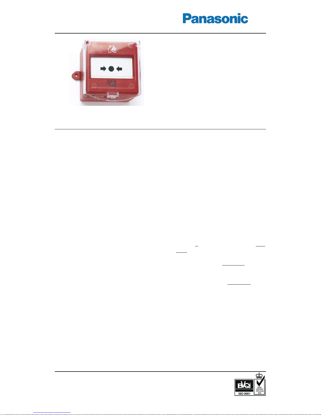
Enclosed
addressable manual
call point
3339
Attractive design compliant with EN54-11. IP rating IP56
Test key for routine testing without breaking the glass element
Protection against accidental operation
General
The call point has an attractive design
compliant with EN54-11, and is surface
mounted in the supplied red back box. It has
a clip retained front cover that makes it easy
to replace the glass element and adds
security since the clips are concealed. The
frangible element is a glass element with a
protective plastic film. To operate the call
point, the glass element is pressed until it is
broken. This will activate the built-in micro
switch, which will generate a fire alarm in
the c.i.e.
Test / cover removal key
Routine testing is made with a supplied test
key, without breaking the glass element.
Inserting the test key simulates the breaking
of the glass element. The call point will be
reset when the test key is pulled out. The
test key is also used to release the security
clips for the front cover removal.
Protective cover
To protect the call point against accidental
operation, a transparent polycarbonate flap
has to be lifted to get access to the glass
element.
Encapsulated circuit
All electronics are encapsulated. Only the
terminal block is accessible from the rear.
Mounted in the supplied red back box with
the tightening gasket on place (see the
opposite page), the IP rating is IP56.
LED indicator
An LED on the front cover indicates fire
alarm generated by the call point.
Furthermore it can via Win512 / Win128 be
set to be flashing or non-flashing:
Flashing LED: Is indicating that the c.i.e. is
communicating with the call point. When
the call point is operated the LED will be
turned on continuously.
Non-flashing LED: The LED is turned off
until the call point is operated and the LED
will be turned on continuously.
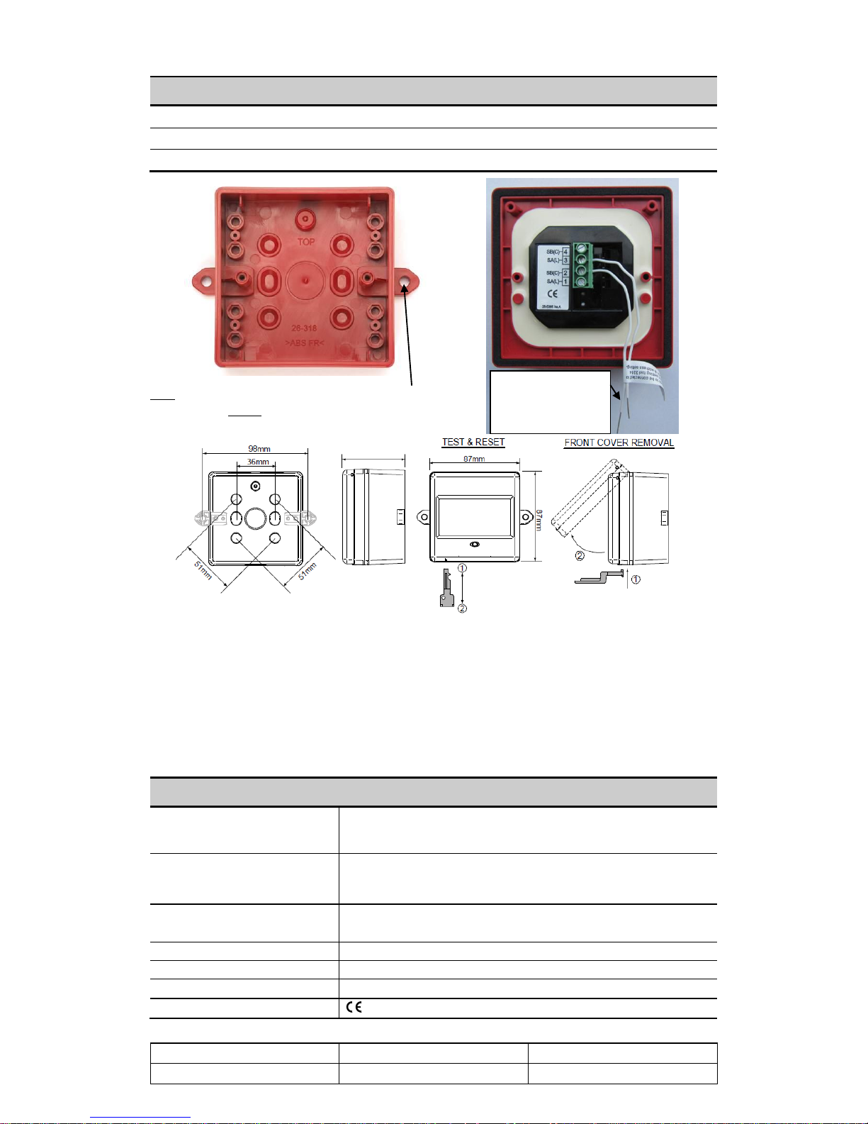
Connections / Settings
The COM loop is connected directly to the
call point via a 4-way terminal block. For
COM loop address setting is the address
setting tool 3314 used. 3314 is also used to
set the call point type and the LED mode:
NORMAL mode: (EBL512 SW
version >2.0 / EBL128). M.c.p. type
3339. (Flashing or non-flashing LED is
set via Win512 / Win128.)
2330 mode: M.c.p. type 2339, flashing
LED. NOTE! This mode is only used
for backwards compatibility.
2312 mode: M.c.p. type 2339, non-
flashing LED. NOTE! This mode is
only used for backwards compatibility.
Two flying leads (wires) are connected to
the terminal block and shall be used for the
address setting tool's connection cable. The
wires shall be disconnected before the COM
loop wires are connected.
Product applications
Used in the systems EBL512 / 128 / 1000 /
2000 and is intended for indoor use in
premises where IP56 rating is required.
All technical features and data are subject to changes without notice, resulting from continuous development and improvement.
Product Leaflet
Date of issue
Revision / Date of revision
MEW00098
2005-04-14
3 / 2010-03-03
Type numbers
3339
Enclosed addressable manual call point
2347
Replacement glass (10 pcs.)
2348
Replacement polycarbonate flap (10 pcs.)
Left: The supplied back box. Mounting lug hole
Ø = 5 mm. Right: The call point backside view
(note the black tightening gasket).
Technical data
Voltage (V DC)
allowed
nominal
12-30
24
Current consumption at nom. volt.
from COM loop (mA)
quiescent / active
2 / 5
Ambient temperature (C)
operating / storage
-10 to +55 / -40 to +85
Ingress Protection rating
IP56
Weight (g)
242
Construction / Colour
ABS / Red (ISO 3864)
Approvals
10 EC Certificate no. 0786-CPD-20918, EN54-11
Flying leads to be
connected to the
Address setting tool
3314 during mode and
address setting
59mm
1)
1)
66mm with the
polycarbonate flap.
How to perform routine testing
Insert the test key into the hole in the front cover.
The glass position will change, indicating
that the call point is operated.
Wait until the LED is turned on, i.e. fire alarm
is activated in the c.i.e.
Pull out the test key and the glass position will
return to normal.
The LED will be turned off when the fire alarm
is reset in the c.i.e.
How to replace the glass element
Lift the polycarbonate flap.
Release the front cover security clips with the test key.
Lift and remove the front cover.
Remove the broken glass element.
Place the top edge of the replacement glass element
against the micro switch plunger and push it upwards
until the glass element is in correct position.
Put back the front cover and lower the polycarbonate flap.
Perform a routine test (see left).
 Loading...