

Panasonic EX-20, MEUEN-EX20 V2.0, EX-23, EX-21 Instruction Manual
INSTRUCTION MANUAL
Rugghölzli 2
CH - 5453 Busslingen
Tel. +41 (0)56 222 38 18
Fax +41 (0)56 222 10 12
mailbox@sentronic.com
www.sentronic.com
Produkte, Support und Service
SEN
TRONIC
AG
Photoelectric Sensor Ultra-compact type
EX-20 Series
MEUEN-EX20 V2.0
Thank you for purchasing products from Panasonic Electric Works SUNX
Co., Ltd. Please read this Instruction Manual carefully and thoroughly for
the correct and optimum use of this product. Kindly keep this manual in a
convenient place for quick reference.
WARNING
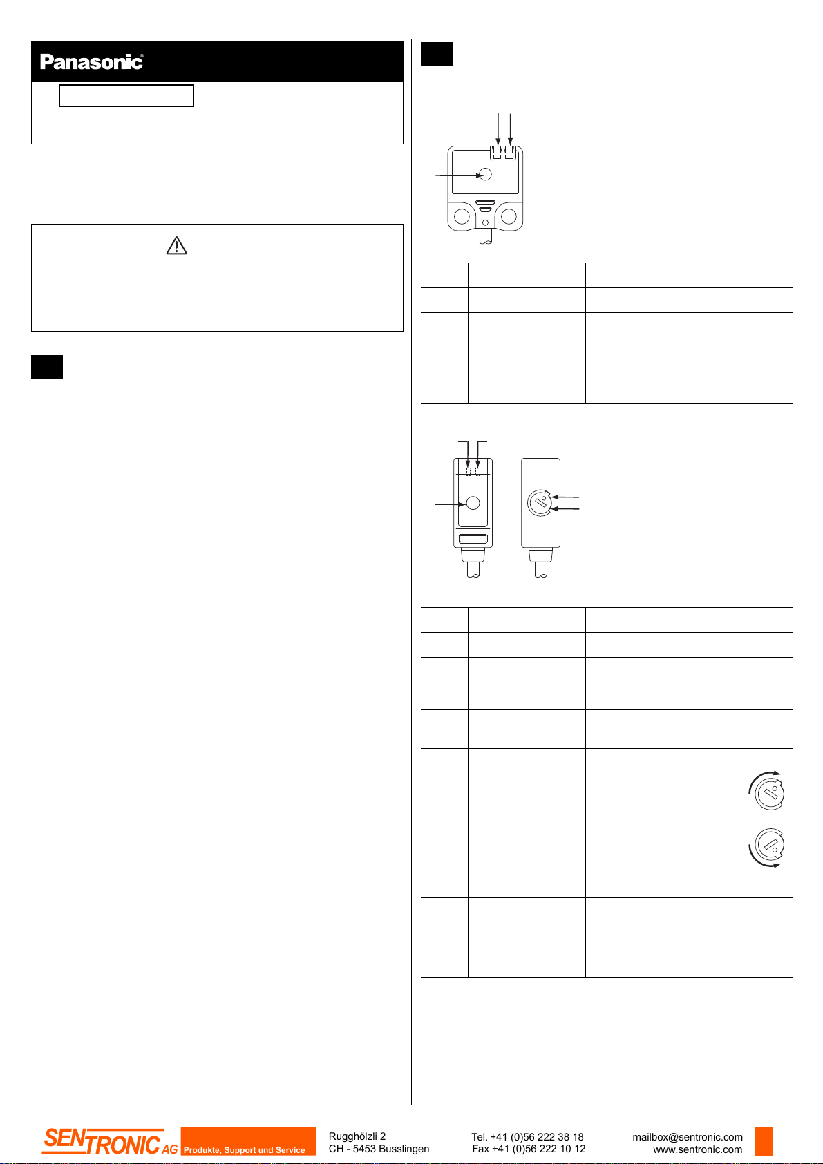
2 PART DESCRIPTION
EX-21
3
2
1
• Never use this product as a sensing device for personnel protection.
• In case of using sensing devices for personnel protection, use
products which meet laws and standards, such as OSHA, ANSI or IEC
etc., for personnel protection applicable in each region or country.
1 CAUTIONS
This product has been developed / produced for industrial use only.
A thin 0.1mm
when pulling on the cable: it may cause cable to break.
EX-24(-PN) types are not incorporated with a sensitivity adjuster.
Maintain adequate distance from reflective objects in the background,
e.g. conveyors, since they may adversely effect sensing.
If a reflective object is present in the background, the sensing of
EX-28A(-PN) may be affected. When setting up the sensor, confirm
that the reflective object has no effect. If the reflective object affects
sensing, removing the reflective object, color it black, or take other
appropriate measures.
If sensors are mounted close together and the ambient temperature is
near the maximum rated value, provide for enough heat radiation /
ventilation.
Make sure that the power supply is off while wiring.
Incorrect wiring will damage the sensor.
Verify that the supply voltage including the ripple is within the rating.
Verify that the supply voltage variation is within the rating.
If power is supplied from a commercial switching regulator, ensure that
the frame ground (F.G.) terminal of the power supply is connected to an
actual ground.
In case noise generating equipment (switching regulator, inverter motor,
etc.) is used in the vicinity of this product, connect the frame ground
(F.G.) terminal of the equipment to an actual ground.
Do not run the wires together with high-voltage lines or power lines or put
them in the same raceway. This can cause malfunction due to induction.
You can extend the cable up to 50m max. with 0.3mm
both emitter and receiver (thru-beam types). However, in order to reduce
noise, make the wiring as short as possible.
Do not use during the initial transient time (0.5s) after the power supply is
switched on.
Ensure that the sensor is not directly exposed to the following light
sources as they may adversely effect sensing performance: fluorescent
light from a rapid-starter lamp, a high frequency lighting device, sunlight
etc.
Do not apply stress directly to the sensor cable joint by forcibly bending
or pulling.
This sensor is suitable for indoor use only.
Avoid dust, dirt and steam. Do not use this sensor in places having
excessive vapor, dust, etc., or where it may come in direct contact with
water or corrosive gas.
Take care that the sensor does not come in contact with oil, grease,
organic solvents such as thinner, etc., strong acid, or alkalines.
2
cable is used for this product. Do not use excessive force
2
or more cable for
No. Part Description
1 Beam axis
2 Stability indicator
(green)
3 Operation indicator
(orange)
EX-23
2
1
No. Part Description
1 Beam axis
2 Stability indicator
3 Operation indicator
4 Operation mode
5 Sensitivity adjuster Emitter only.
3
L
D
(green)
(orange)
switch
Receiver only.
Lit when detection is stable according
to the parameters set.
Receiver only.
Lit when the output is ON.
4
5
Receiver only.
Lit when detection is stable according
to the parameters set.
Receiver only.
Lit when the output is ON.
Receiver only.
• L: Light-ON
Turn the operation mode
switch fully clockwise until it
stops.
• D: Dark-ON
Turn the operation mode
switch fully
counterclockwise until it
stops.
Sensing range increased when turned
clockwise.
See “SENSITIVITY ADJUSTMENT” on
page 2.
L
D
L
D
1
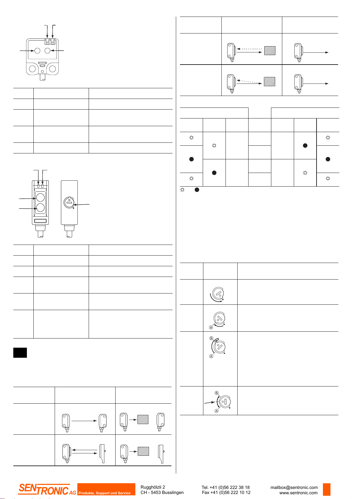
EX-24
Rugghölzli 2
CH - 5453 Busslingen
Tel. +41 (0)56 222 38 18
Fax +41 (0)56 222 10 12
mailbox@sentronic.com
www.sentronic.com
Produkte, Support und Service
SEN
TRONIC
AG
2
3
Sensor type
Light received
condition
Dark condition
1
4
No. Part Description
1 Receiver
2 Stability indicator
(green)
3 Operation indicator
Lit when detection is stable according to the parameters set.
Lit when the output is ON.
(orange)
4 Emitter
EX-22, EX-26, EX-28, EX-29
3
2
1
4
MAXMAX
5
Diffuse
Sensor
Sensing object
Sensor
reflective
Convergent
reflective,
Sensor
Sensing object
Sensor
Narrow view
reflective
Relation between output and indicators
Light-ON Dark-ON
Stability
indicator
Operation
indicator
Output
ON
OFF
Sensing
condition
Stable
light
Unstable
light
Unstable
dark
Stable
dark
Output
OFF
ON
Operation
indicator
Stability
indicator
= lit, = unlit
Procedure
This procedure assumes that “Light-ON” is set for the operation mode. If
“Dark-ON” is the operation mode, the output will behave the other way
around.
No. Part Description
1 Emitter
2 Receiver
3 Stability indicator
(green)
4 Operation indicator
Lit when detection is stable according to the parameters set.
Lit when the output is ON.
(orange)
5 Sensitivity adjuster Sensing range increased when
turned clockwise.
See “SENSITIVITY ADJUSTMENT”
on page 2.
3 SENSITIVITY ADJUSTMENT
To understand sensitivity adjustment, you must first understand the difference between the “light received” and the “dark” condition.
Do not confuse the “light received” and “dark” condition with the operation
modes “Light-ON” and “Dark-ON”!
Sensor type
Light received
condition
Dark condition
Use the accessory screwdriver and turn the adjuster slowly. Using
excessive force will damage the adjuster.
When using EX-22(-PN) at a sensing range of 50mm or less, the
sensitivity adjustment range is extremely narrow.
Step
Sensitivity
adjuster
1 Turn the sensitivity adjuster fully counter-
Max
Description
clockwise to the minimum sensitivity position
(●).
2 In the “light received” condition, turn the sen-
Max
sitivity adjuster slowly clockwise to find point
A where the sensor output turns ON.
3 In the “dark” condition, turn the sensitivity
Max
adjuster clockwise until the sensor output
turns ON.
*1
*1
Turn it back slowly to confirm point B, where
the sensor output just turns OFF.
*1
If the sensor output does not turn ON even
when the sensitivity adjuster is turned fully
clockwise, point B is the position at MAX.
4 The position exactly between points A and B
Max
is the optimum sensing position.
Thru-beam
Retroreflective
Emitter
Sensor Reflector
Receiver
Emitter Receiver
Sensing object
Sensor
Sensing object
Reflector
*1
Remember, this only applies if the operation mode is Light-ON.
2
 Loading...