

Panasonic MDF-U74V, MDF-U55V Operating Instructions Manual
Please read these instructions carefully before using this product, and save this operating instructions
for future use.
See page 42 for all Model Numbers.
MDF-U74V
MDF-U55V
MDF-U55V
MDF-U74V
MDF-U55V
Ultra-Low Temperature Freezer
Operating Instructions

1
CONTENTS
INTRODUCTION P. 2
PRECAUTIONS FOR SAFE OPERATION P. 3
LABELS ON THE UNIT P. 7
SYMBOLS ON THE UNIT P. 7
ENVIRONMENTAL CONDITIONS P. 8
INTENDED USE AND PRECAUTIONS P. 8
FREEZER COMPONENTS P. 9
Control panel P.11
INSTALLATION SITE P.12
INSTALLATION P.13
START-UP OF UNIT P.14
CHAMBER TEMPERATURE SETTING P.15
KEY LOCK FUNCTION P.15
ALARM TEMPERATURE SETTING P.16
SETTING OF ALARM RESUME TIME P.17
REMOTE ALARM TERMINAL P.18
MONITOR OF FREEZER STATUS P.19
CHANGE OF COMPRESSOR DELAY TIME P.20
CHANGE OF DOOR ALARM DELAY TIME P.21
ALARMS & SAFETY FUNCTIONS P.22
ROUTINE MAINTENANCE P.23
Cleaning of cabinet P.23
Cleaning of condenser filter P.23
Defrosting of inside wall P.24
CALIBRATION P.24
TROUBLESHOOTING P.25
DISPOSAL OF UNIT P.26
Recycle of battery P.26
Decontamination of unit P.26
DISPOSAL OF BATTERY P.31
TEMPERATURE RECORDER (OPTION) P.32
Setting of MTR-85H P.32
Setting of MTR-G85C P.34
Installation of MTR-G85C and MTR-85H P.36
BACKUP COOLING KIT (OPTION) P.36
SMALL INNER DOOR (OPTION) P.38
DRAWER RACK (OPTION) P.38
INTERFACE BOARD (OPTION) P.38
Installation of MTR-480 P.38
INVENTORY RACK (OPTION) P.39
SPECIFICATIONS P.40
PERFORMANCE P.42
SAFETY CHECK SHEET P.43
2
INTRODUCTION
Read this operating instructions carefully before using the appliance and follow the instructions for
safety operation.
Our company never guarantee any safety if the appliance is used for any objects other than intended
use or used by any procedures other than those mentioned in this operating instructions.
Keep this operating instructions in an adequate place to refer to it as necessary.
The contents of the operating instructions will be subjected to change without notice due to the
improvement of performance or functions.
Contact our sales representative or agent if any page of the operating instructions is lost or page order
is incorrect.
Contact our sales representative or agent if any point in this operating instructions is unclear or if there
are any inaccuracies.
No part of this operating instructions may be reproduced in any form without the expressed written
permission of our company.
CAUTION
Our company guarantees the product under certain warranty conditions. Our company in no
way shall be responsible for any loss of content or damage of content.
3
PRECAUTIONS FOR SAFE OPERATION
It is imperative that the user complies with this operating instructions
as it contains important safety advice.
Items and procedures are described so that you can use this unit correctly and safely.
If the precautions advised are followed, this will prevent possible injury to the user and
any other person.
Precautions are illustrated in the following way:
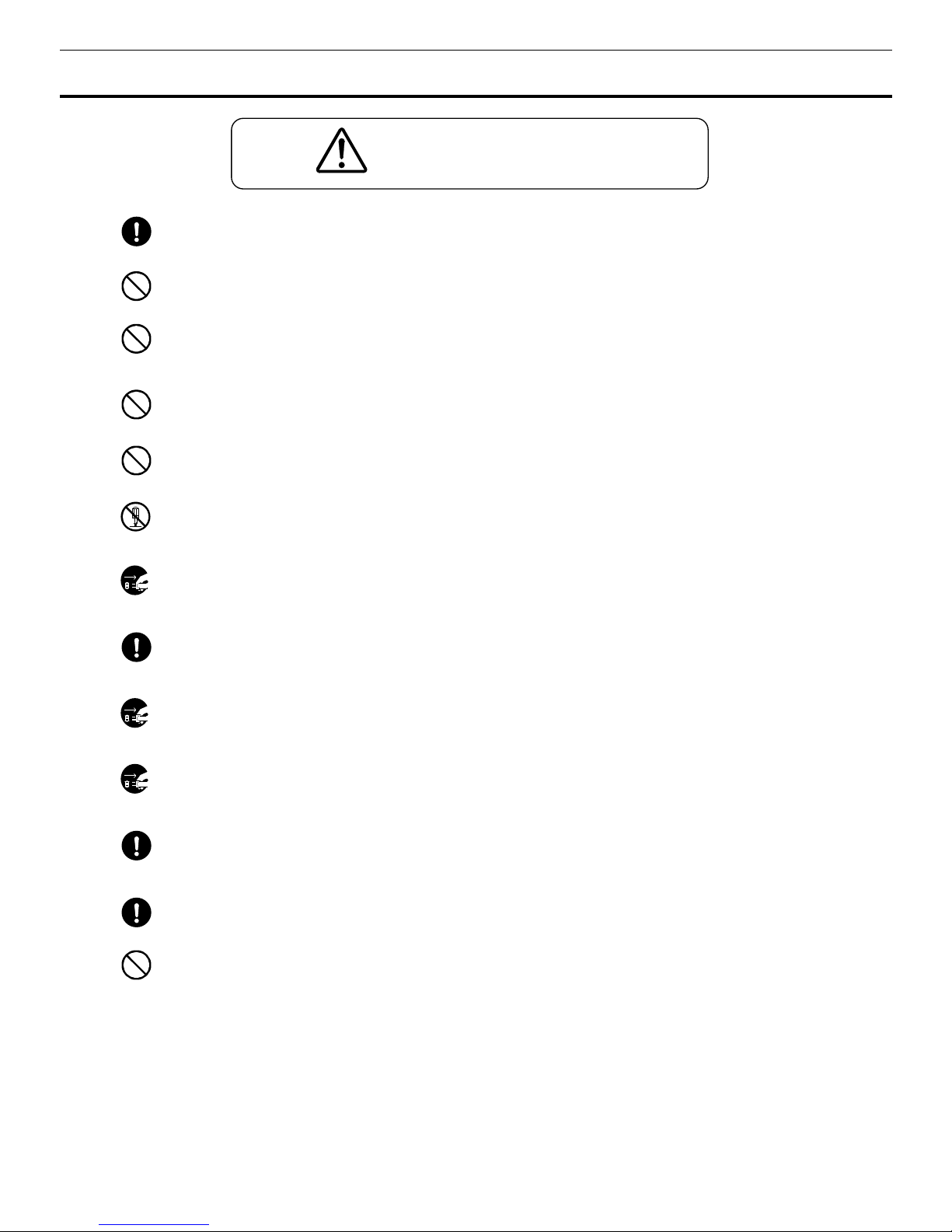
WARNING
Failure to observe WARNING signs could result in a hazard to personnel
possibly resulting in serious injury or death.
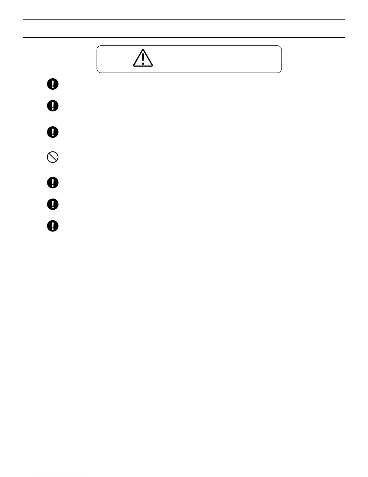
CAUTION
Failure to observe CAUTION signs could result in injury to personnel and
damage to the unit and associated property.
Symbol shows;
this symbol means caution.
this symbol means an action is prohibited.
this symbol means an instruction must be followed.
Be sure to keep this operating instructions in a place accessible to users of this unit.
Some warning and/or caution labels are attached on the unit. Following shows the description of such
labels.
NOTE:
As with any equipment that uses CO2 gas, there is a likelihood of oxygen depletion in the vicinity
of the equipment. It is important that you assess the work site to ensure there is suitable and
sufficient ventilation. If restricted ventilation is suspected, then other methods of ensuring a
safe environment must be considered. These may include atmosphere monitoring and
warning devices.
4
PRECAUTIONS FOR SAFE OPERATION
Do not use the unit outdoors.
Current leakage or electric shock may result if the unit is exposed to
rain water.
Only qualified engineers or service personnel should install the unit.
The installation by
unqualified personnel may cause electric shock or fire.
Install the unit on a sturdy floor and take an adequate precaution to prevent the unit from
turning over.
If the floor is not strong enough or the installation site is not adequate, this may result
in injury from the unit falling or tipping over.
Never install the unit in a humid place or a place where it is likely to be splashed by water.
Deterioration of the insulation may result which could cause current leakage or electric shock.
Never install the unit in a flammable or volatile location.
This may cause explosion or fire.
Never install the unit where acid or corrosive gases are present
as current leakage or electric
shock may result due to corrosion.
Always ground (earth) the unit to prevent electric shock.
If the power supply outlet is not
grounded, it will be necessary to install a ground by qualified engineers.
Never ground the unit through a gas pipe, water main, telephone line or lightning rod.
Such
grounding may cause electric shock in the case of an incomplete circuit.
Connect the unit to a power source as indicated on the rating label attached to the unit.
Use of
any other voltage or frequency other than that on the rating label may cause fire or electric shock.
Never store volatile or flammable substances
in this unit if the container cannot be sealed. These
may cause explosion or fire.
Do not insert metal objects such as a pin or a wire into any vent, gap or any outlet on the unit.
This may cause electric shock or injury by accidental contact with moving parts.
Use this unit in safe area when treating the poison, harmful or radiate articles.
Improper use
may cause bad effect on your health or environment.
Turn off the power switch (if provided) and disconnect the power supply to the unit prior to any
repair or maintenance
of the unit in order to prevent electric shock or injury.
Do not touch any electrical parts (such as power supply plug) or operate switches with a wet
hand.
This may cause electric shock.
WARNING
5
PRECAUTIONS FOR SAFE OPERATION
Ensure you do not inhale or consume medication or aerosols
from around the unit at the time of
maintenance. These may be harmful to your health.
Never splash water directly onto the unit
as this may cause electric shock or short circuit.
Never put containers with liquid on the unit
as this may cause electric shock or short circuit when
the liquid is spilled.
Never bind, process, or step on the power supply cord, or never damage or break the power
supply plug.
A broken supply cord or plug may cause fire or electric shock.
Do not use the supply cord if its plug is loose.
Such supply cord may cause fire or electric shock.
Never disassemble, repair, or modify the unit yourself.
Any such work carried out by an
unauthorized person may result in fire, or electric shock or injury due to a malfunction.
Disconnect the power supply plug if there is something wrong with the unit.
Continued
abnormal operation may cause electric shock or fire.
When removing the plug from the power supply outlet, grip the power supply plug,
not the cord.
Pulling the cord may result in electric shock or fire by short circuit.
Disconnect the power supply plug
before moving the unit. Take care not to damage the power
cord. A damaged cord may cause electric shock or fire.
Disconnect the power plug when the unit is not used for long periods.
Keeping the connection
may cause electric shock, current leakage, or fire due to the deterioration of insulation.
If the unit is to be stored unused in an unsupervised area for an extended period,
ensure that
children do not have access and that doors cannot be closed completely with a key.
The disposal of the unit should be accomplished by appropriate personnel.
Remove doors to
prevent accidents such as suffocation.
Do not put the packing plastic bag within reach of children
as suffocation may result.
WARNING
6
PRECAUTIONS FOR SAFE OPERATION
This unit must be plug into a dedicated circuit protected by branch circuit breaker.
Use a dedicated power source
as indicated on the rating label attached to the unit. A multiple-tap
may cause fire resulting from abnormal heating.
Connect the power supply plug to the power source firmly after removing the dust on the plug.
A dusty plug or improper insertion may cause a heat or ignition.
Never store corrosive substances such as acid or alkali
in this unit if the container cannot be
sealed. These may cause corrosion of inner components or electric parts.
Check the setting when starting up of operation after power failure or turning off of power
switch.
The stored items may be damaged due to the change of setting.
Be careful not to tip over the unit
during movement to prevent damage or injury.
Prepare a safety check sheet (copy the last page)
when you request any repair or maintenance for
the safety of service personnel.
CAUTION
7
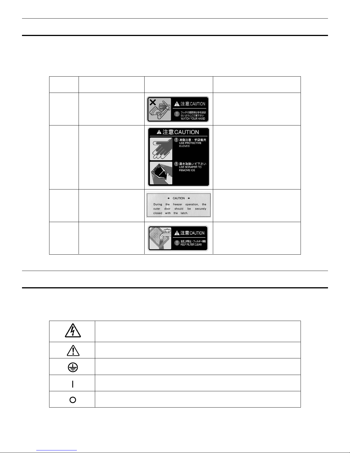
LABELS ON THE UNIT
Warning safety labels applied to the ultra-low temperature freezer
Users are advised to avoid accidents by carefully reading the warnings and cautions contained on warning
labels at key locations on the interior and exterior of the ultra-low temperature freezer.
Possible
Danger
Warning/Caution Type
Location of Danger
Warning/Caution Label Description of Danger
Personal
injury
Hazardous Latch
Latch
Dangerous to put a hand.
Personal
injury
Frostbite and frost
Interior
Frostbite and frost caution label.
Sample
damage
Chamber temperature
Interior
Forgets to close a door and latch.
Sample
damage
Chamber temperature
Interior
Rise in temperature is prevented.
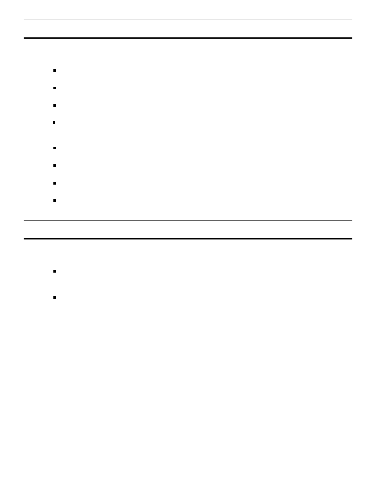
SYMBOLS ON THE UNIT
The symbols are attached to the ultra-low temperature freezer. The following table describes the
symbols.
This symbol is attached to covers that access high-voltage electrical components to
prevent electric shock. Only a qualified engineer or service personnel should be
allowed to open these covers.
This symbol indicates that caution is required. Refer to product documentation for
details.
This symbol indicates an earth.
This symbol means “ON” for a power switch.
This symbol means “OFF” for a power switch.
8
ENVIRONMENTAL CONDITIONS
This equipment is designed to be safe at least under the following conditions (based on the IEC61010-1):
Indoor use;
Altitude up to 2000 m;
Ambient temperature 5oC to 40oC;
Maximum relative humidity 80% for temperature up to 31oC decreasing linearly to 50% relative humidity
at 40
o
C;
Mains supply voltage fluctuations up to ±10% of the nominal voltage;
Transient overvoltages up to the levels of OVERVOLTAGE CATEGORY II;
Temporary OVERVOLTAGES occurring on the mains supply;
Applicable pollution degree of the intended environment (POLUTION DEGREE 2 in most cases)
INTENDED USE AND PRECAUTIONS
This equipment is designed for low temperature storage of human cells, organs, plasma and DNAs.
The effective storage period depends on the sample condition and storage temperature. It is
necessary to determine the storage temperature and period suitable for the purpose.
For the live cells, the lower storage temperature should be required for long term storage. It is
recommended to store the live cells at -130
℃
or lower.
9
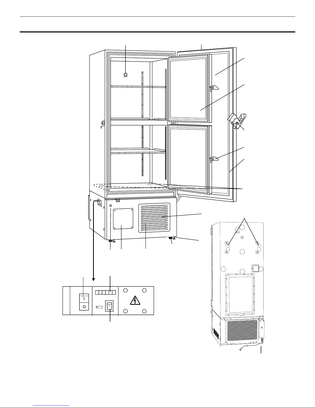
FREEZER COMPONENTS
14
Rear side
Power cord
11(inside)
7 (inside)
1
2
3
6
8
12
7
4
9
10
13
5
16
17
15

10
FREEZER COMPONENTS
1. Control panel (on the upper front of the outer door):
Used for temperature setting and indication
of operating status is displayed on the panel. See page 11 for details.
2.
Outer door:
To open the door, grip the handle. On closing, lock the outer door latch completely.
3. Inner door:
The operation of the inner door should be quick to minimize the temperature rise in
chamber. Lock the inner door latch completely when the inner door is closed. The inner door is
removable for cleaning or defrosting. See page 24 “Routine maintenance”.
4. Outer door latch:
Always lock the latch when the outer door is closed.
5. Inner door latch:
Always lock the inner door latch when the inner door is closed.
6. Magnetic door gasket:
This provides a tight door seal and prevents cold air leak. Keep clean.
7. Access port (rear and bottom):
This is used for leading a cable and sensor of a measuring
equipment, or nozzle of backup cooling kit to chamber.
8. Air intake vent (grille):
Do not block this vent to keep the proper cooling performance.
9. Leveling foot:
The height of the freezer can be adjusted by this screw type foot. Keep the unit in
level at the installation.
10. Caster:
4 casters are provided to facilitate moving of the cabinet. For the installation, adjust the
leveling foot so that the front 2 casters cannot contact with the floor.
11. Condenser filter (behind the grille):
This filter prevents the dust from accumulating on the
condenser. The dusty condenser filter may cause failure of refrigerating device. Clean the condenser
filter once a month. See page 23 “Routine maintenance” for the cleaning.
12. Space for temperature recorder:
A temperature recorder (optional component) can be attached
here. See page 32“ Temperature recorder (Option)”.
13. Key lock:
Turn clockwise to 180o with a key and the outer door is securely locked.
14. Fixture (on back side):
2 fixtures are provided as spacers between the cabinet and wall and also
serve as hooks to fix the unit. See page 13 “Installation”.
15. Power switch:
This is for turning ON/OFF the power to the unit. ON – “I” OFF – “○”
16. Remote alarm terminal:
This is used to notice an alarm condition of the unit to remote location.
Refer to page 18 “Remote alarm terminal”.
17. Battery switch:
This is a switch for a battery for power failure alarm. Normally, turn on this switch.
Be sure to turn off this switch if the freezer is not in operating for the long period (over one month).
NOTE:
Fix the shelf supports and shelves securely. Incomplete installation may cause injury or damage.
Never touch the storage items with wet hands. Touching with the wet hands may cause frostbite.
.
11
FREEZER COMPONENTS
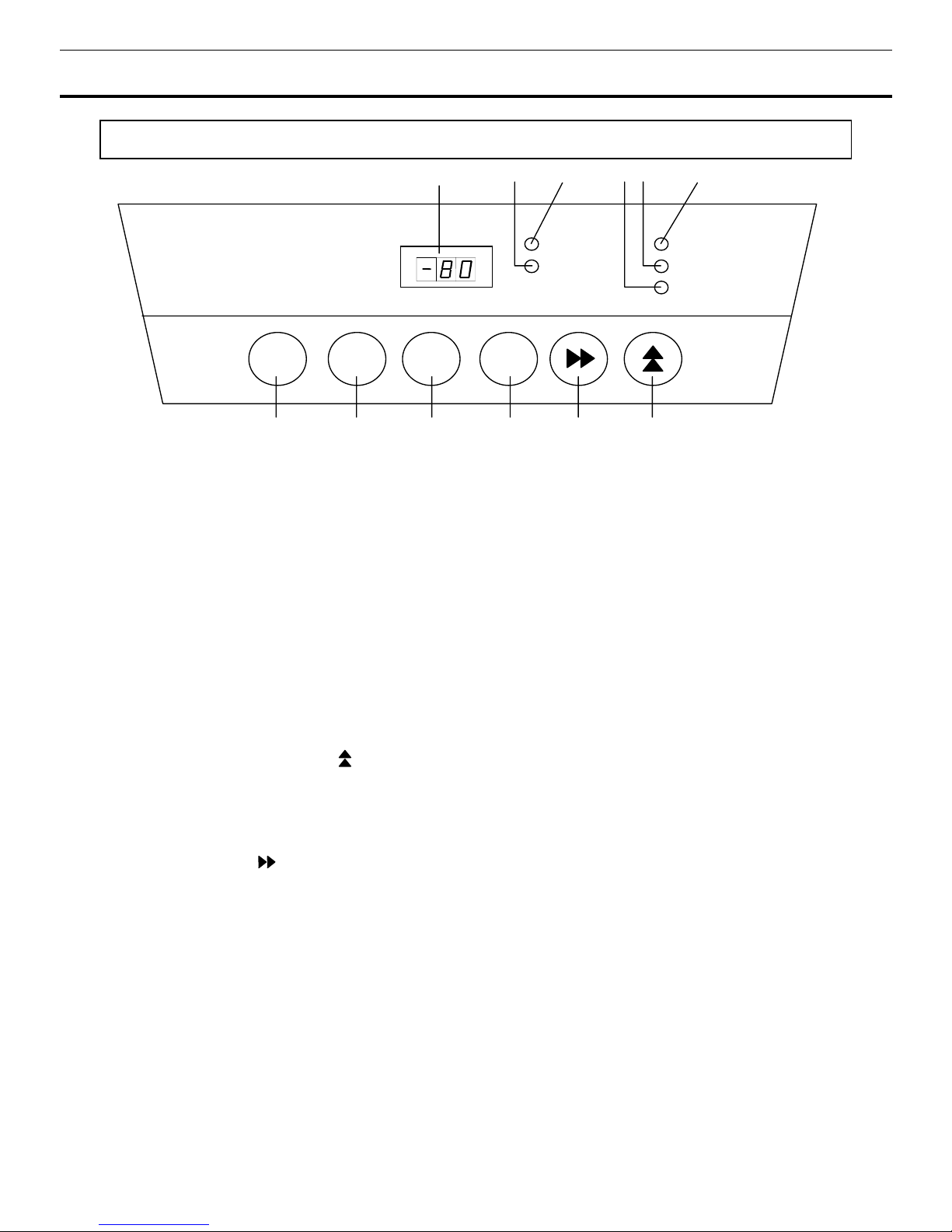
Control panel
1. Digital temperature indicator:
This indicator shows the present chamber temperature or set
temperature.
2. Status monitor lamp (STATUS):
This lamp lights when environmental condition or status gets worse
or the unit is out of normal operation.
3. Battery check lamp (BATTERY):
This lamp lights to recommend the battery replacement. This
lamp blinks when a fan motor is replacement. For the replacement, consult our sales representative or
agent.
4. Door check lamp (DOOR):
This lamp lights when the outer door is open.
5. Alarm lamp (ALARM):
This lamp is flashed during alarm condition.
6. Filter check lamp (FILTER):
This lamp lights and buzzer sound when the excessive dust is
accumulated on the condenser filter. When this lamp lights, clean the condenser filter following the
procedure on page 23.
7. Numerical value shift key ( ):
Pressing this key in the setting mode causes the numerical value to
shift. “ON-OFF” of key lock can be selected by pressing this key in the key lock setting mode. By
pressing this key for more than 5 seconds in the temperature display mode leads setting mode for alarm
temperature, alarm resume time ,compressor delay time and door alarm delay time. Refer to page 16,
17,20 and 21 for details respectively.
8. Digit shift key ( ):
Pressing this key in the setting mode causes the changeable digit to shift. Key
lock setting is available by pressing this key for more than 5 seconds in the temperature display mode.
Refer to page 15 for details.
9. Set key (SET):
Temperature setting mode is led by pressing this key and the changeable digit is
flashed. By pressing this key again, the setting is memorized. The setting mode returns to the
temperature display mode automatically when 90 seconds has passed without any key operation.
10. Status key (STATUS):
By pressing this key in the event of the status monitor lamp ON, the status
code is displayed on the digital temperature indicator. This key is not effective when the freezer is
running normally. See page 19 for details.
11. Alarm test key (ALARM TEST):
To check the alarm system during freezer operation. Pressing
this key with the battery switch ON gets the alarm lamp to flash, the remote alarm to operate, and the
buzzer to sound.
12. Buzzer stop key (BUZZER):
To silence the audible alarm under alarm condition, press this key.
The buzzer during alarm test cannot be silenced by this key. But the remote alarm is not canceled.
12
BATTER
Y
STATUS
FILTER
A
LARM
DOOR
TEMPERATURE
(
o
C
)
BUZZER
A
LARM
TEST
STATUS SET
11 10 9 8
7
1 32 654

12
INSTALLATION SITE
To operate this unit properly and to obtain maximum performance, install the unit in a location with the
following conditions:
A location not subjected to direct sunlight
Do not install the unit under direct sunlight. Installation in a location subjected to direct sunlight cannot
obtain the intended performance.
A location with adequate ventilation
Leave at least 10 cm around the unit for ventilation. Poor ventilation will result in a reduction of the
performance and consequently the failure.
A location away from heat generating sources
Avoid installing the unit near heat-emitting appliances such as a heater or a boiler etc. Heat can
decrease the intended performance of the unit.
A location with little temperature change
Install the unit under stable ambient temperature. The allowable ambient temperature is between +5 and
+30
o
C.
A location with a sturdy and level floor
Always install the unit on a sturdy and level floor. The uneven floor or tilted installation may cause failure
or injury. Install the unit in stable condition to avoid the vibration or noise. Unstable condition may
cause vibration or noise.
Install the unit on a sturdy floor.
If the floor is not strong enough or the installation site is not
adequate, this may result in injury from the unit falling or tipping over.
Select a level and sturdy floor for installation.
This precaution will prevent the unit from tipping.
Improper installation may result in water spillage or injury from the unit tipping over.
A location not prone to high humidity
Install the unit in the ambient of 80% R.H. or less humidity. Installation under high humidity may cause
current leakage or electric shock.
Do not use the unit outdoors.
Current leakage or electric shock may result if the unit is exposed to
rain water.
Never install the unit in a humid place or a place where it is likely to be splashed by water.
Deterioration of the insulation may result which could cause current leakage or electric shock.
A location without flammable or corrosive gas
Never install the unit in a flammable or volatile location. This may cause explosion or fire or may result in
the current leakage or electric shock by the corrosion of the electrical components.
A location without the possibility of anything fall
Avoid installing the unit in the location where anything can fall down onto the unit. This may cause the
breakdown or failure of the unit.
13
INSTALLATION
1. Removing the packaging materials and tapes
Remove all transportation packaging materials and tapes. Open the doors and ventilate the unit. If the
outside panels are dirty, clean them with a diluted neutral dishwashing detergent. (Undiluted detergent
can damage the plastic components. For the dilution, refer to the instruction of the detergent.) After the
cleaning with the diluted detergent, always wipe it off with a wet cloth. Then wipe off the panels with a dry
cloth.
Note:
Remove the cable tie banding the power supply cord. Prolonged banding may cause the corrosion of the
cord coating.
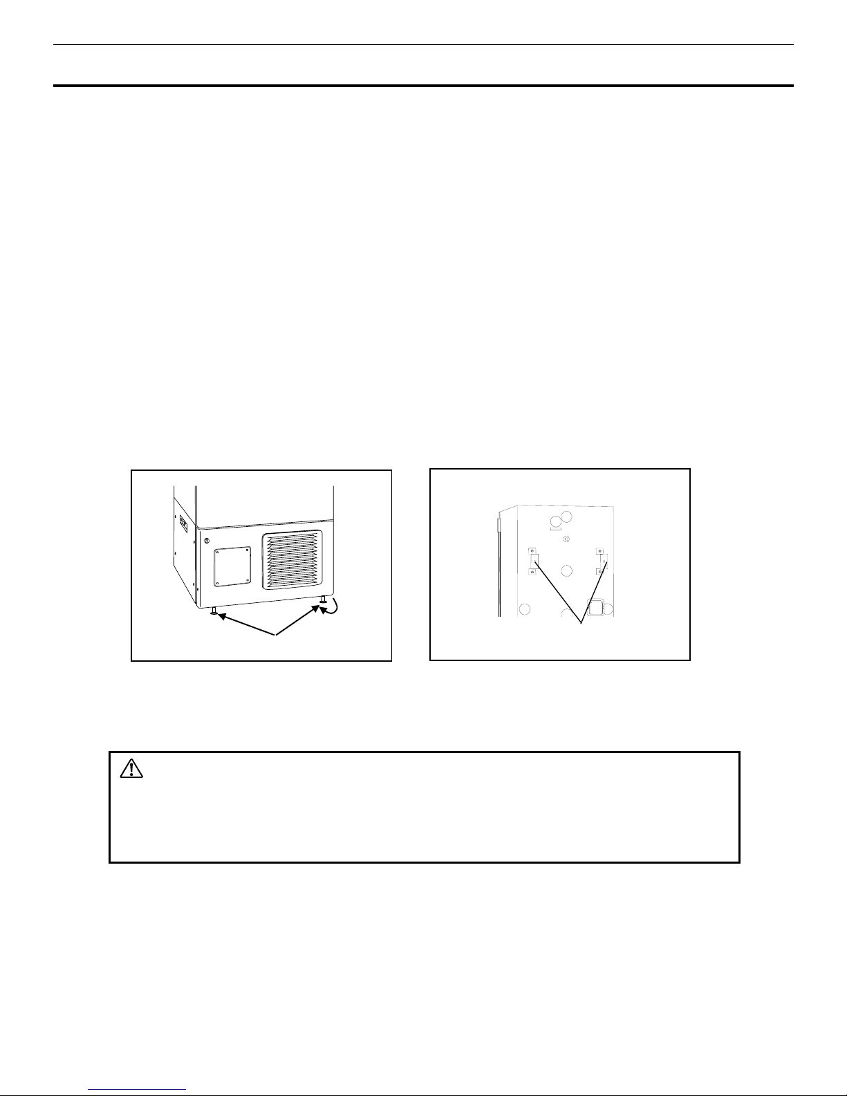
2.
Adjusting the leveling foot
Extend the leveling feet by rotating them counterclockwise to contact them to the floor. Ensure the unit is
level. (Fig. 1)
3.
Fixing the unit
Two fixtures are attached to the rear of the frame. Fix the frame to the wall with these fixtures and rope
or chain. (Fig. 2)
4.
Ground (earth)
The ground (earth) is for preventing the electric shock in the case of the electrical insulation is somehow
degraded. Always ground the unit at the time of installation.
WARNING
Use a power supply outlet with ground (earth)
to prevent electric shock. If the power supply outlet is
not grounded, it is necessary to install a ground by qualified engineers.
Never ground the unit through a gas pipe, water main, telephone line or lightning rod.
Such
grounding may cause electric shock in the case of an incomplete circuit.
5. Installing the earth leakage breakers
This product is to connect a earth leakage breaker to the power supply side of the product.
Contact our sales representative or agent at the time of installation of the
earth leakage
breaker.
Fixture
Fig. 2
Fig.1
Leveling foot
 Loading...