

Panasonic MDF-DU702VH, MDF-DU502VH Service Manual

Service Manual
Ultra-Low Temperature Freezer
MDF-DU502VH
MDF-DU702VH
Panasonic Healthcare Co., Ltd.
Biomedical Div.
SM0000002-03
Effective model
This service manual is effective for following models.
Model
Voltage
Frequency
MDF-DU502VH-PA
220V
60Hz
MDF-DU502VH-PE
220V/230V/240V
50Hz
MDF-DU702VH-PA
220V
60Hz
MDF-DU702VH-PE
220V/230V/240V
50Hz

Contents
Page
Features, Caution
----------------------------------------------------------
1
S p e c i f i c a t i o n s
----------------------------------------------------------
2
-Structural s p e c ifications
-Control spec if i c ations
-Performance s p ecificat i ons
D i m e n s i o n s
----------------------------------------------------------
5
Cooling unit parts
----------------------------------------------------------
7
R e f i r i g e r a t i o n c i r c u i t s
--------------------------------------------------
9
C o m p o n e n t s o n P C B
--------------------------------------------------
10
C o n n e c t i o n s o n P C B
--------------------------------------------------
11
E l e c t r i c p a r t s
-------------------------------------------------------
12
Sp e c i f i c a t i o n of s en s or
--------------------------------------------------
13
W i r i n g d i a g r a m
-------------------------------------------------------
14
C i r c u i t d i a g r a m
-------------------------------------------------------
15
O p e r a t i o n
------------------------------------------------------- - - ----------
18
C o n tr o l s p e c if i c a t i o n s
---------------------------------------------------
25
I n v e t e r s i g n a l
----------------------------------------------------------
33
P a r t s l a y o u t
----------------------------------------------------------
34
R e p a i r i n g u n i t / G a s c h a r g e
------------------------------------------
36
T e s t d a t a
----------------------------------------------------------
52
MDF-DU502VH, MDF-DU702V H
-Pull-down & P ull-up tem p e r ature
-Pull-down t e m perature
-Pull-down p r e s sure
-Pull-down c urrent-inp u t
-Temperature u n iformit y ( 1 7points meas u r e d)
-Amount of po w e r consumpti o n
-Cycle runni ng
Bac kup cooli n g kit instal la t ion and sett i n g procedure
---------------
64

F e a t u re s
Energy saving
Inverter control of compressor
Improvement of storage efficiency
Auto air intake port
Enhancement of safety functions
New control panel with LCD touch panel
Caution
*Parts replacement and option unit installation must be done by trained service engineer.
*Service engineer must refer to the section “Electric parts” and “Cooling unit parts”
about the parts for those operations.
-1-
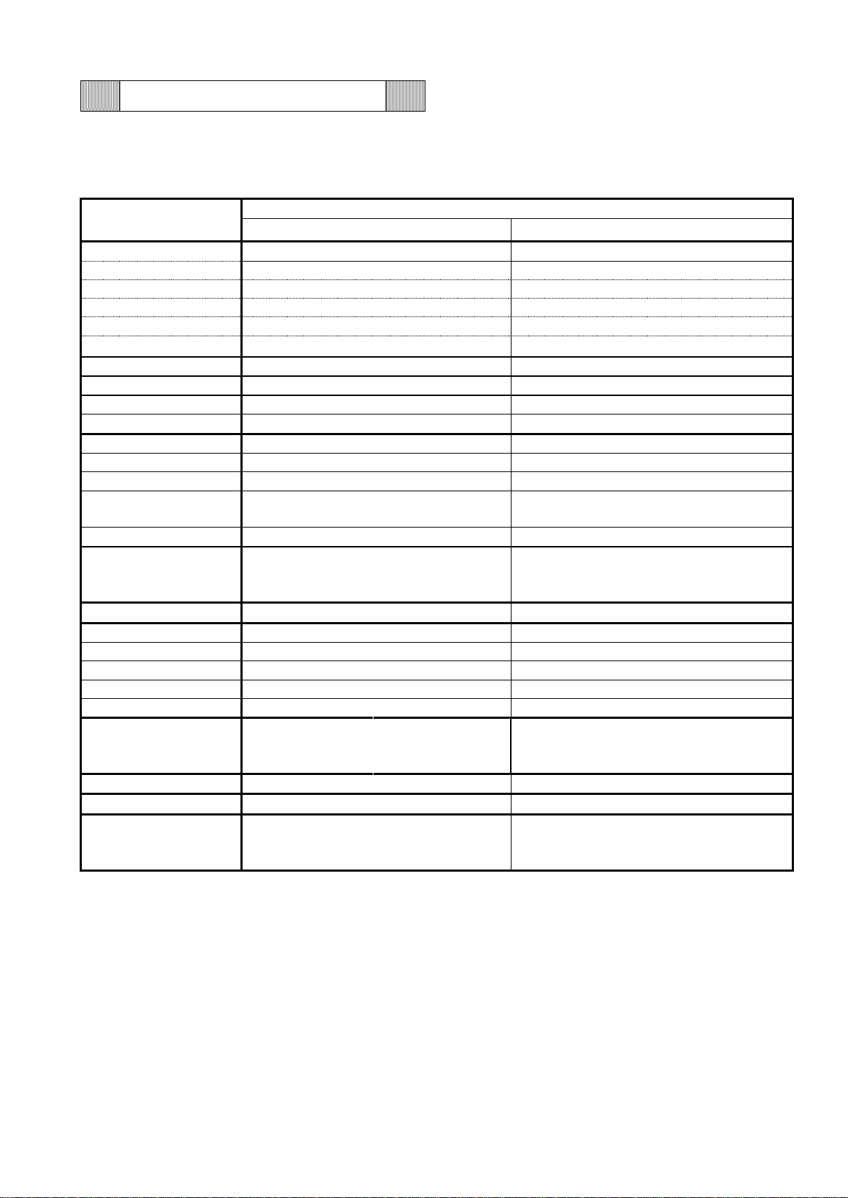
Specifications
Structural specifications
Item
MDF-DU502VH
MDF-DU702VH
Name
Ultra-Low Temperature Freezer
Exterior dimensions
W 790 × D 882 × H 1993 mm
W 1030 × D 882 × H 1993 mm
Interior dimensions
W 630 × D 600 × H 1400 mm
W 870 × D 600 × H 1400 mm
Effective capacity
528 liters
729 liters
Exterior
Painted steel
Interior
Painted steel
Outer door
Painted steel
Inner door
2
Shelf
3
Outer door latch
1
Outer door lock
1
Insulation
Rigid polyurethane foam+VIP PLUS
Access port
3 (back x 1, bottom x 2)
Auto air intake port
Inside of control panel (built-in anti freezing heater)
Manual air intake port
Product left side lower part
Compressor
VNEU213U (single-phase 220-240V 50/60Hz)x 2
Evaporator
High: Cascade, Low: Tube on sheet
Condenser
High: Fin and tube, Low: Cascade
Refrigerant
High Temp. side
Low Temp. side
High Temp. side
Low Temp. side
R290 135 g ±5 g
R170 70 g ±3 g
n-pentane 10 g
(16cc) 0+3 g
(12.5%wt)
R290 135 g ±5 g
R170 85 g ±3 g
n-pentane 12 g
(19cc) 0+3 g
(12.5%wt)
Refrigerant oil
Ze-NIUSL22SA
Battery
For power failure alarm, Lead storage battery, DC6 V 7200 mAh,
Auto-recharge
Weight
246 kg
278 kg
Accessories
1 key, 1 scraper, 1 stick for air intake port cleaning
Optional components
Temperature recorder: (MTR-85H MTR-G85C),
Recorder fixing (MDF-S3085, MTR-85H)
Recorder sensor Cover:(MTR-DU700SF)
Backup cooling kit:(MDF-UB7);For Liquid CO2
Small inner door
(MDF-5ID4, MDF-5ID5)
Small inner door
(MDF-7ID4, MDF-7ID5)
Drawers (MDF-50R)
-
Storage rack (MDF-70SC)
Inventory rack (IR-224U, IR-316U)
Interface board (MTR-L03)*; For LAN
Interface board (MTR-480)*; For RS-232C/RS-485
* For the data acquisition system MTR-5000 user only.
-2-
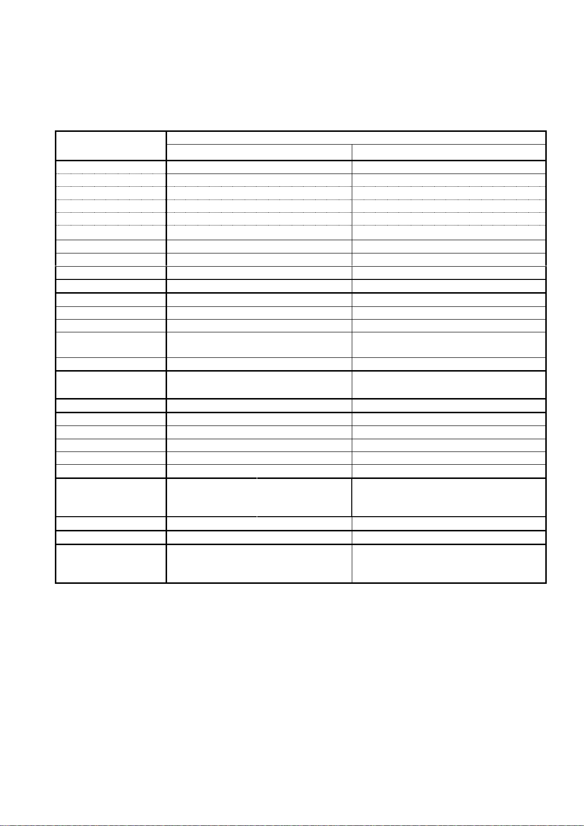
Control specifications
Item
MDF-DU502VH
MDF-DU702VH
Temperature controller
Microprocessor control system: LCD touch panel input
Settable range : -90 ℃~-50 ℃ (unit:1 ℃)
Memorized by Non-volatile memory
Temperature sensor
Platinum resistance (Type: PT 1000 Ω)
Temperature display
WVGA full color LCD
Digital display (Unit: 1 ℃)
Alarms
High / Low
temp. alarm
SV±5 ℃~±40 ℃, changeable (default:±10 ℃)
When the chamber temperature exceeds the alarm set temperature,
"Alarm" is displayed alternately in normal characters and reverse video
in the alarm display field and chamber temperature blinks. After 15 min.
(0-15 min. changeable, default: 15℃), "Warning" is displayed in the
message display field, buzzer beeps and remote alarm activates and
chamber temperature blinks.
Door alarm
When the door opens, "Open" is displayed alternately in normal
characters and reverse video in the alarm display field. After 2 min.
(0-15 min. changeable), buzzer beeps, no remote alarm activates.
Fan lock alarm
No detection function.
Power failure
"Warning" is displayed alternately in normal characters and reverse
video in the alarm display field. And the notification is displayed in the
message display field. Buzzer beeps and the remote alarm activates.
Filter alarm
Filter alarm indicator is lit when the excessive dust is accumulated on
the condenser filter. When this indicator is lit, clean the condenser filter.
Remote alarm
Remote alarm terminal 3P; contact capacity DC 30 V, 2 A (Max)
Remote alarm activates when temp. alarm or power failure occur.
Parts
replacement
notification
Battery age
Two type of battery accumulation time display in service mode. At
replacement time, it is informed in the message display field.
Fan motor age
Fan motor accumulation time display in service mode. Replacement
notification is not performed.
Status
Ambient
temperature
abnormality
When the sensor is out of the range of 35 ℃ from 0 ℃ , the
notification display in the message display field.
Supply voltage
drop
No detection function.
High-load
operation
display
When low side compressor operation rate is over 95 %, the notification
display in the message display field.
Self-diagnosis function
When a sensor is failed, the notification display in the message display
field. Buzzer beeps and remote alarm activates.
Compressor protection
Overload relay (internal)
Detected value of filter sensor is 50 ℃ or more.
"Warning" is displayed alternately in normal characters and reverse
video in the alarm display field and the notification is displayed in the
message display field. Buzzer beeps and remote alarm activates.
Key lock
Selection of ON or OFF by slide in Key Lock mode.
OFF: Unlocked ON: Locked
-3-
Performance specifications
Item
MDF-DU502VH
MDF-DU702VH
Cooling performance
-86 ℃ (AT;30 ℃, no load)
Temperature control range
-86 ℃~-50 ℃ (ambient temperature; 30 ℃, no load)*
Rated voltage
AC 220/230/240 V
Rated frequency
50 Hz (PE)
60 Hz (PA)
Rated power consumption
430 W (Max. 820 W)(PA)
420 W (Max. 840 W)(PE)
545 W (MAX 930W/ 945 W/ 960 W) (PE)
550 W (MAX 930 W) (PA)
Rated heat radiation
1548 kJ/h (Max. 2952 kJ/h)
1512 kJ/h (Max. 3024 kJ/h)
1962 kJ/h
(Max.3348 kJ/h /3402 kJ/h /3456 kJ/h) (PE)
1980 kJ/h (Max. 3348 kJ/h))(PA)
Noise level
52 dB [A] (background noise; 20 dB)
Maximum pressure
2200 kPa
2200 kPa
*Maximum cooling performance.
The chamber temperature can be reached at -86 ℃ at ambient temperature 30 ℃ with no load.
-4-
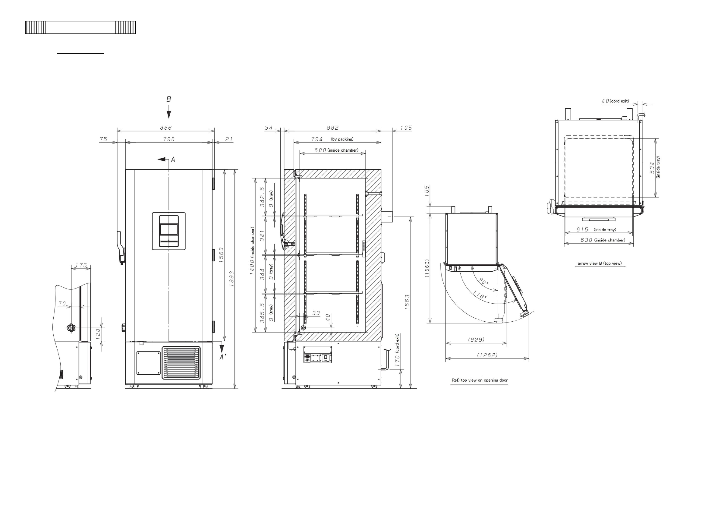
Dimension
MDF-DU502VH
-5-

MDF-DU702VH
-6-
Cooling unit parts
MDF-DU502VH
1Φ220-240V 50/60Hz
Parts description
Specification
Circuit H(Left side at rear view)
Circuit L(Right side at rear view)
Compressor
Type
VNEU213U
VNEU213U
Compressor cord
LDDG000200
LDDG000200
Rated power supply
Single phase, 220-240 V, 50/60 Hz
Single phase, 220-240 V, 50/60 Hz
Refrigeration oil
Ze-NIUSL22SA Q’ty:500 cc
Ze-NIUSL22SA Q’ty:500 cc
Cooling method
Forcible air circulation(partially)
Forcible air circulation(partially)
Inverter
Type
VENEU213U
VENEU213U
Inverter code
LDLB041800
LDLB041800
power supply
220-240 V, 50/60 Hz
220-240 V, 50/60 Hz
Condenser
Type
Finless tube
Finless tube
Condenser
12 columns x 2 lines 5pitch Fin 50spc
Coil pipe Φ6.35 mm
Pre-condenser
W250 mm
(within 1column x6lines pre-con)
Frame pipe
Φ6.35mm
Evaporator
Type
Accumulator
Cascade condenser, Shell & Tube
Φ80 mm
Φ38 mm
Tube on sheet, Φ7.94mm
(Sharing with interior)
Accumulator
Φ38mm
Capillary tube
Resistance
78 PSI
4.0 kg/cm2
Length
3000 mm
2000 mm
Outer diameter
Φ2.4 mm
Φ1.8 mm
Inner diameter
Φ1.2 mm
Φ0.9 mm
Refrigerant
TYPE
R-290
Amount
135g ±5 g
TYPE
R-170
n-pentane
Amount
70g ±3 g
10g (16cc)-0+3g
Dryer
4AXH-9 18 g
4AXH-9 55 g
Condensing fan
Material: ABS Blade: 4 pcs. 230 mm
Material: ABS Blade: 4 pcs. Φ230 mm
Condensing fan
motor
Type
SV4-11AB5P
(440VAC,1.0μF running condenser)
SV4-11AB5P
(440VAC,1.0μF running condenser)
-7-
MDF-DU702VH
1Φ220-240V 50/60Hz
Parts description
Specification
Circuit H(Left side at rear view)
Circuit L(Right side at rear view)
Compressor
Type
VNEU213U
VNEU213U
Compressor cord
LDDG000200
LDDG000200
Rated power supply
Single phase, 220-240 V, 50/60 Hz
Single phase, 220-240 V, 50/60 Hz
Refrigeration oil
Ze-NIUSL22SA Q’ty:500 cc
Ze-NIUSL22SA Q’ty:500 cc
Cooling method
Forcible air circulation(partially)
Forcible air circulation(partially)
Inverter
Type
VENEU213U
VENEU213U
Inverter code
LDLB041800
LDLB041800
power supply
220-240 V, 50/60 Hz
220-240 V, 50/60 Hz
Condenser
Type
Finless tube
Finless tube
Condenser
12 columns x 2 lines 5pitch Fin 50spc
Coil pipe Φ6.35mm
Pre-condenser
W250 mm
(within 1column x6lines pre-con)
Frame pipe
Φ6.35mm
Evaporator
Type
Cascade condenser, Shell & Tube
Φ80mm
Tube on sheet, Φ7.94mm
(Sharing with interior)
Accumulator
Φ38mm
Capillary tube
Resistance
78PSI
4.0 kg/cm2
Length
3000mm
2000mm
Outer diameter
Φ2.4mm
Φ1.8mm
Inner diameter
Φ1.2mm
Φ0.9mm
Refrigerant
TYPE
R-290
Amount
135g ±5 g
TYPE
R-170
n-pentane
Amount
85g ±3 g
12g (19cc)-0+3g
Dryer
4AXH-9 18 g
4AXH-9 55 g
Condensing fan
Material: ABS Blade: 4 pcs. 230mm
Material: ABS Blade: 4 pcs. Φ230mm
Condensing fan
motor
Type
SV4-11AB5P
(440VAC,1.0μF running condenser)
SV4-11AB5P
(440VAC,1.0μF running condenser)
-8-
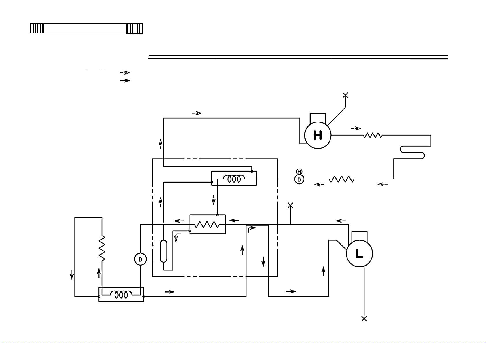
Refrigeration circuit
High temp.
Cascade Condenser
Dehydrator (L)
Evaporator
Pre-Condenser
Cascade
Dehydrator
Frame Pipe
Compressor (L)
Suction heat
exchanger
Capillary Tube (L)
Capillary Tube (H)
Low temp.
Condenser
Compressor (H)
Binary refrigerating cuircuit 〈cascade system〉 〈MDF-DU502VH/DU702VH)
-9-
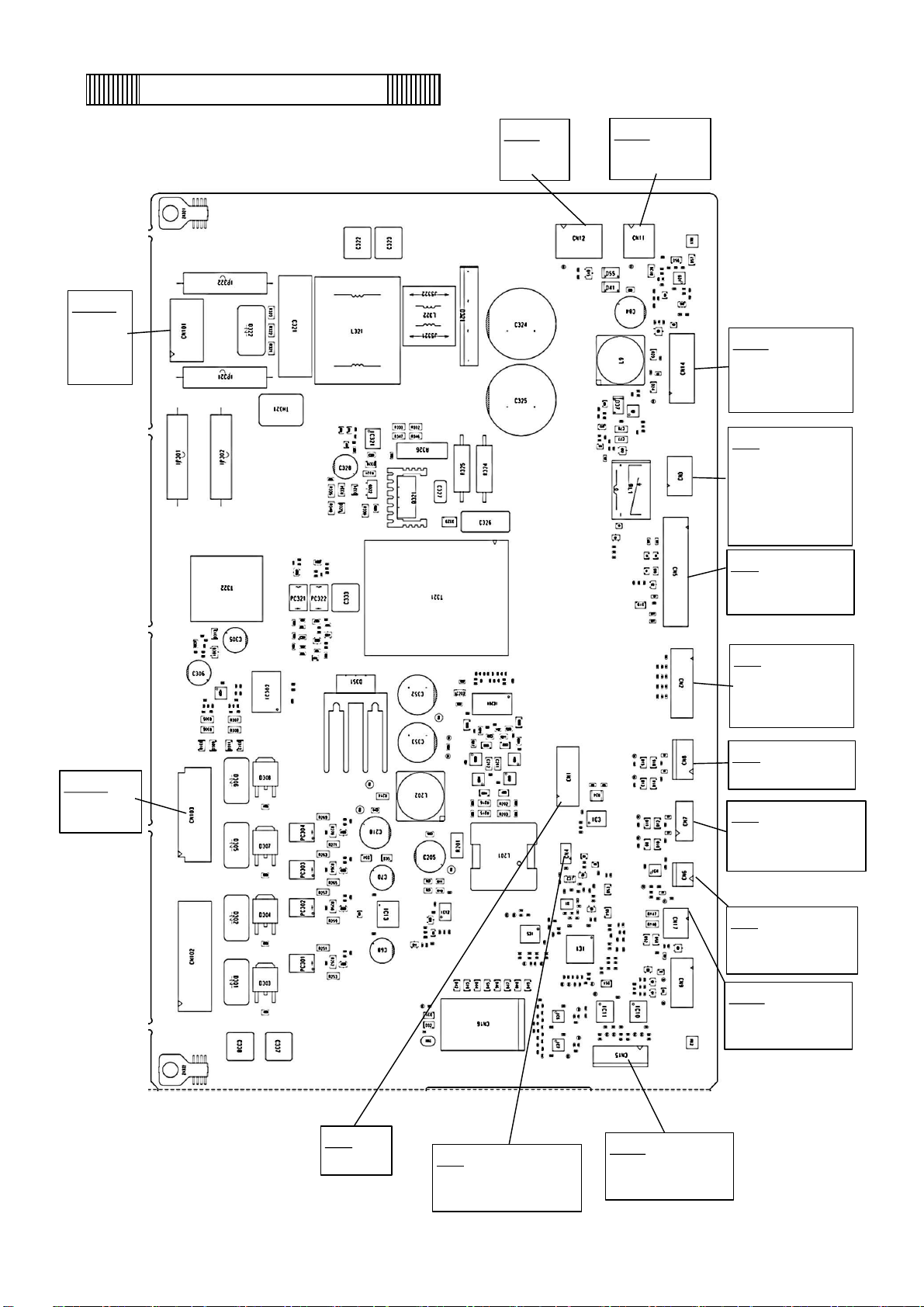
Components on PCB
CN8
#1-#2 AT sensor
CN101
#1,#4
Power SW
Recorder
(option)
CN2
#1-#6
MTR-480,MTR-L03
(option)
CN6
#1-#2
Temp. sensor
CN103
#1,#3:
FM cond.
CN12
#1,#3
Battery SW
CN14
#1-#6
Backup Battery
PCB
CN5
#1,#7:USB PCB
#8,#9:Door SW
CN11
#1,#2
Main Battery SW
CN3
Remote alarm
terminal
#1: COM
#2: N.O.
#3: N.C.
CN7
#1-#2 Cascade sensor
#3-#4 Filter sensor
CN17
#1-#2
AIP heater
CN15
#1-#3 Inverter L
#4-#6 Inverter H
CN4
#1-#2
Jumper for emulator
CN1
Emulator
-10-
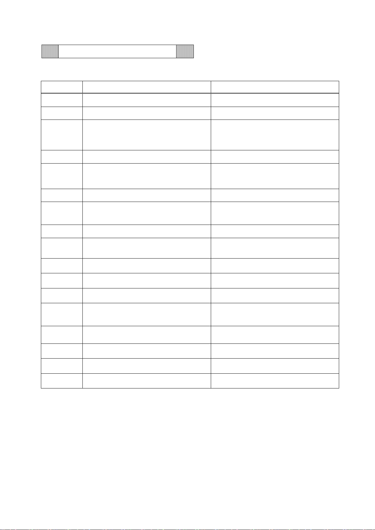
Connections on PCB
The following shows connections of connector on Main PCB.
Connector
Connects to
Usage
CN1
Emulator
To version up firmware
CN2
#1~#6: MTR-480/MTR-L03 (Option)
To connect with MTR-480/MTR-L03.
CN3
Remote alarm terminal
#1: COM
#2: N.O.
#3: N.C.
Remote alarm contact outputs.
CN4
#1~#2 Jumper
To upgrade firmware version
CN5
#1,#7:USB PCB
#8,#9:Door switch
To connect with LCD PCB
To detect door open and shut
CN6
#1~#2:Temp. sensor
To control chamber temperature
CN7
#1~#2:Cascade sensor
#3~#4:Filter sensor
To detect temperature of cascade
To detect temperature of filter
CN8
#1~#2:AT sensor
To detect ambient temperature
CN9
#1~#4:Unused
CN11
#1,#2:Main battery switch
To supply power during power failure
CN12
#1,#3:Battery switch
To supply power during power failure
CN14
#1~#6:Back-up battery charging PCB
To control battery charging
CN15
#1~#3:Inverter L
#3~#6:Inverter H
To control inverter L
To control inverter H
CN16
#1~#4:Unused
CN17
#1,#2: Auto air intake port (AIP) heater
To control AIP heater
CN101
#1,#4:Recorder, Power switch
To supply power to PCB
CN103
#1、#3:Fan motor condenser
To control condensing fan motor
-11-
Compressor(A)(B) Type VNEU213U VNEU213U
Rating
220-240 V, 50/60 Hz 220-240 V, 50/60 Hz
Inverter Type VCCHP2456 VCCHP2456
Rating
220-240 V, 50/60 Hz 220-240 V, 50/60 Hz
Condensing fan motor Type SV4-11AB5P SV4-11AB5P
Rating 230 V,10 W 230 V,10 W
Capi. Tube Heater(A),(B) Rating 230V,12W 230V,12W
MDF-DU702VH Resistance(25℃) 4700Ω 4700Ω
S/N:~18010001 only
Temp. sensoor Type Pt (THC-663) Pt (THC-663)
Rating 1000Ω 1000Ω
Cascade sensor Type 502AT-11 502AT-11
Rating 5 kΩ,25 ℃ 5 kΩ,25 ℃
Filter sensor Type 502AT-11 502AT-11
Rating 5 kΩ,25 ℃ 5 kΩ,25 ℃
Door Switch Type SDKNA20700 SDKNA20700
Rating 5 V 5 mA 5 V 5 mA
Battery Type LC-P067R2J LC-P067R2J
Rating 6 V 7.2 AH 6 V 7.2 AH
Battery Switch
Type SLE6A2-5 SLE6A2-5
Rating 4 A 250 VAC 4 A 250 VAC
Power Switch Type JW-L21RRK-P4G JW-L21RRK-P4G
Rating 16A, 250VAC 16A, 250VAC
Power Cord Plug U3 250VAC 15A K3 250VAC 16A
Length 3.8m 3.5m
ーPA
MDF-DU502VH
MDF-DU702VH
ーPE
Electric parts
-12-
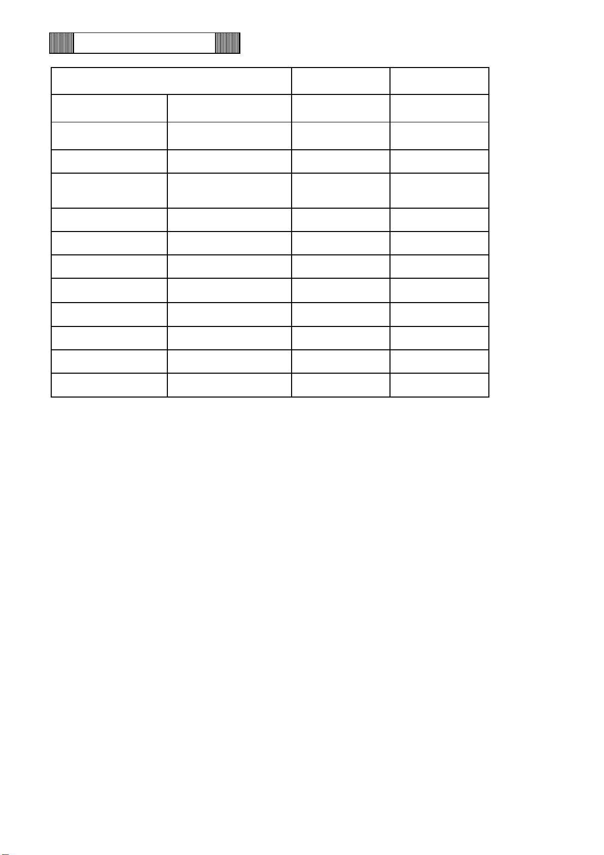
Specifications of sensor
The following shows the temperature in thermal sensor (502AT-11) and its resistance value.
Temp.
(℃)
Resistance
Value (kΩ)
Temp.
(℃)
Resistance
Value (kΩ)
Temp.
(℃)
Resistance
Value (kΩ)
-50
154.6
-7
17.93
12
8.167
-45
116.5
-6
17.16
13
7.853
-40
88.91
-5
16.43
14
7.553
-35
68.19
-4
15.74
15
7.267
-30
52.87
-3
15.08
16
6.993
-25
41.21
-2
14.46
17
6.731
-20
32.44
-1
13.86
18
6.481
-19
30.93
0
13.29
19
6.242
-18
29.51
1
12.74
20
6.013
-17
28.16
2
12.22
25
5.000
-16
26.88
3
11.73
30
4.179
-15
25.66
4
11.25
35
3.508
-14
24.52
5
10.80
40
2.961
-13
23.43
6
10.37
45
2.509
-12
22.39
7
9.960
50
2.137
-11
21.41
8
9.569
55
1.826
-10
20.48
9
9.196
60
1.567
-9
19.59
10
8.840
-8
18.74
11
8.496
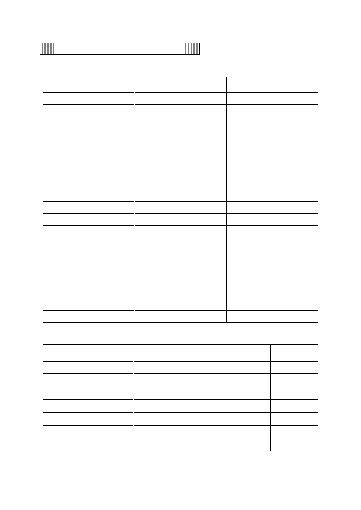
The following shows the temperature in thermal control sensor (PT1000Ω) and its resistance value.
Temp.
(℃)
Resistance
Value (Ω)
Temp.
(℃)
Resistance
Value (Ω)
Temp.
(℃)
Resistance
Value (Ω)
-140
452.8
-70
730.3
0
1000.0
-130
493.0
-60
769.3
10
1038.0
-120
533.1
-50
808.1
20
1076.0
-110
572.9
-40
846.7
30
1113.8
-100
612.6
-30
885.2
40
1151.4
-90
652.0
-20
923.6
50
1189.0
-80
691.3
-10
961.9
60
1226.4
-13-
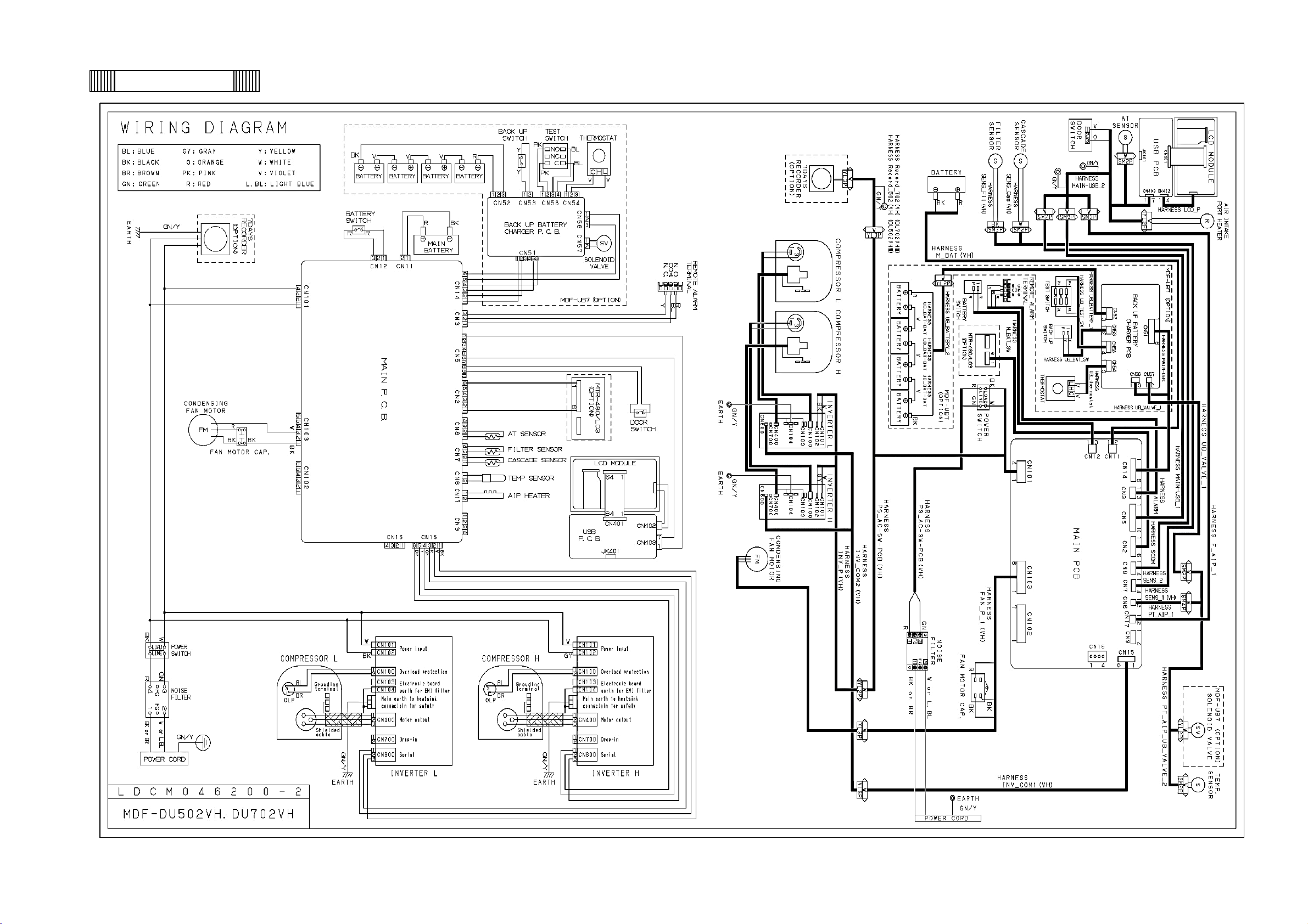
Wiring Diagram
-14-
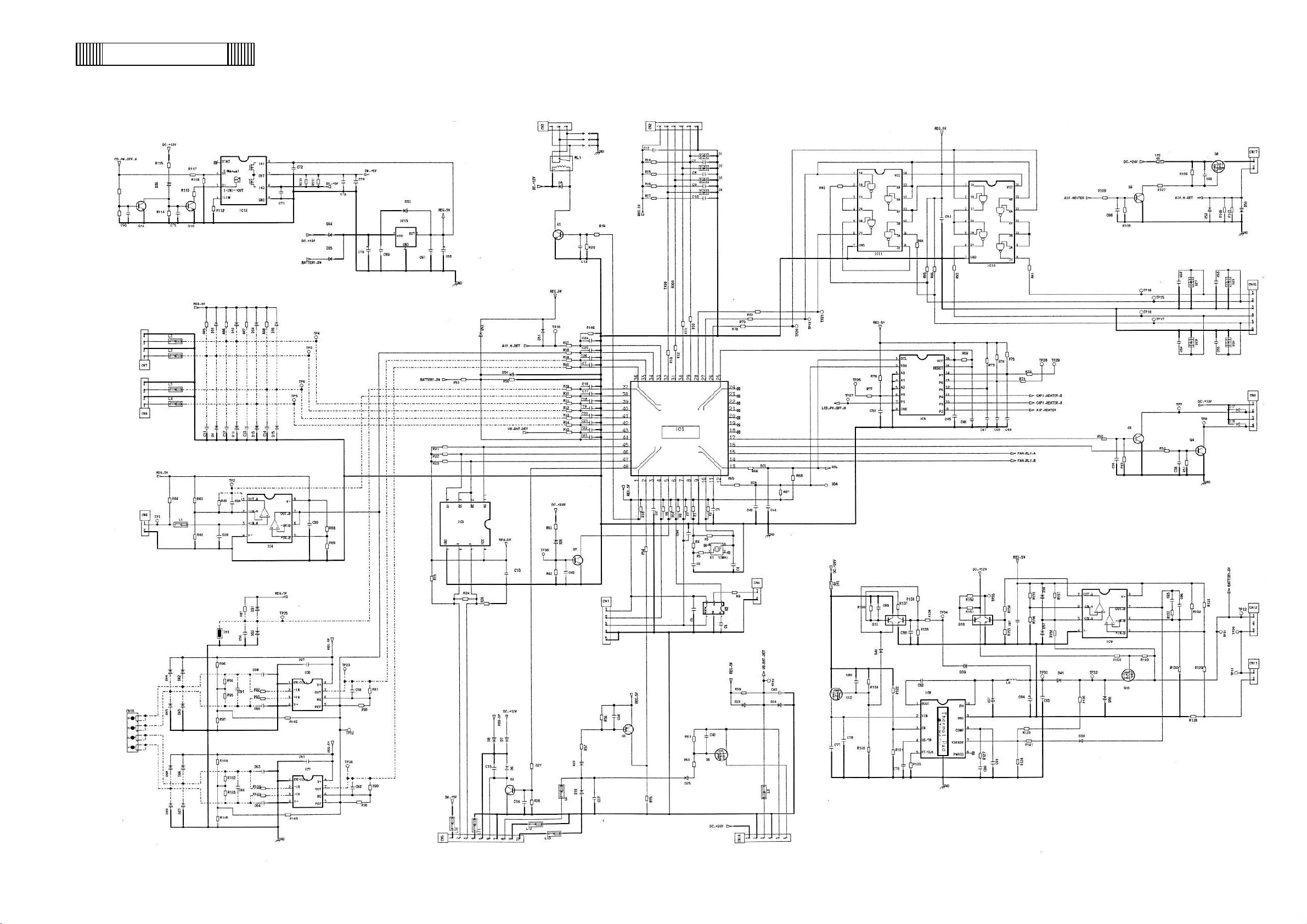
main
Circuit Diagram
-15-
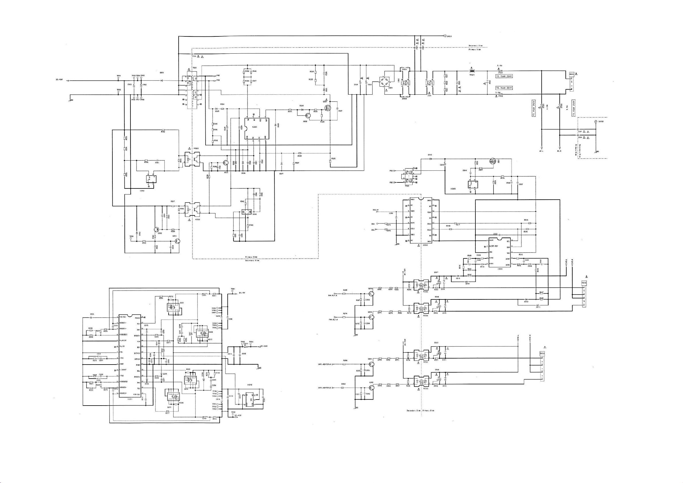
power
-16-
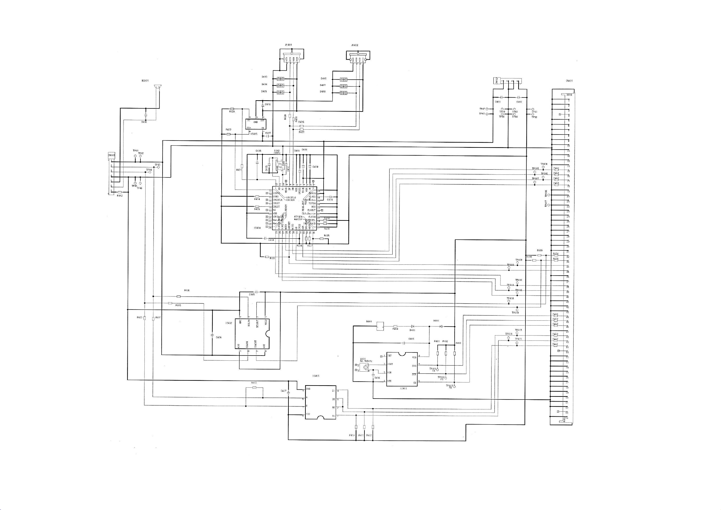
USB
-17-
Operation
How to operate Service # 1 and Service # 2 on the service menu is described below. For other operations on the LCD, refer
to the instruction manual.
CAUTION) Firmware update, compressor, FAN, and cap heater settings affect basic performance.
Be careful when operating.
Term
Function
Runtime
Display the accumulate time of Main battery, Backup battery FAN A and FAN B, Reset
them.
Version UP
Update the firmware of main board and touch panel.
Temp. Calibration
Chamber adjustment method.
System Configuration #1
Setting Capi. Heater and its timer, compressors, Fan A/B .
Status
Monitoring of chamber temp. , ambient temp, comp. evaporator and fan.
System Configuration #2
Turning On/Off of AIP heater, and Backup. Setting overload alarm delay..
Reset Data
Initialization of data, and flash memory. Setting model code.
Error Log
Output of error log data.
Setup Data
Input and output the data.
Other Setting
Turning On/Off Screen Capture, Demo Mode, Self-diagnosis Function and FAN Alarm.
-18-
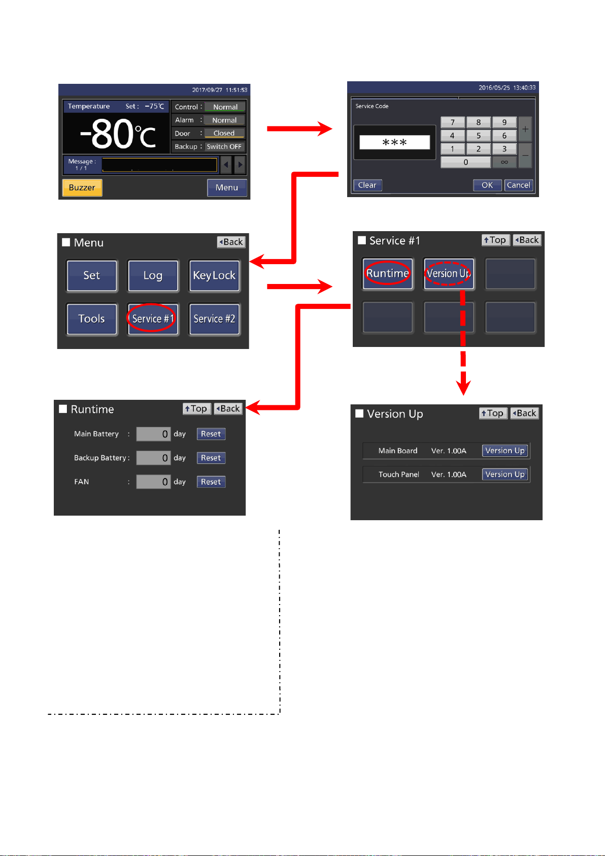
(Runtime,Version Up)
Main Battery
Main Battery accumulated time
Backup Battery
Backup Battery accumulated time
FAN
FAN accumulated time
When each part replace, reset corresponding
data.
・Confirm the existence of file in predefined folder of USB
memory.
・If file is not existence, message “File not found.” is displayed
in “Notice” screen and the process end.
・If file is a existence, if it is not compatible model, "Confirm
firmware" is displayed and the process is terminated. If it is a
compatible model, "Confirm firmware rewrite · · ·" is displayed
and when “Yes” is selected, version upgrade of the touch
panel embedded software is started, and when “No” is
selected, the process is ended.
・During version up, wheel appear in the screen.
・ When version upgrade is completed, "Firmware rewrite
complete. ..." is displayed.
・If an error (other than Verify check) occurs during version
upgrade, "Firmware rewrite failure ... ..." is displayed
・If a Verify error occurs in the Verify check, "Verify check
NG. ..." is displayed.
Service code “384”
※When some version up files are plurality, the first found file is used for version up
※During appearance “wheel”, all operations are not able to receive.
※“OK” button in “Result” screen is disable, and all operations are not able to receive.(unless user turn off power)
※“OK” button in “Error” screen is disable, and all operations are not able to received. (unless user turn off power)
※During version up , no communication is not carried out and no log.is not output.
※If you cancel after or during upgrade, restart the main power supply.
Keep touching MENU KEY (5 sec)
Move to Service Code input display, so
input “384” or “335232”
Move to Menu display, touch service #1
key.
Move to Service #1
display, touch Runtime
or Version Up key
Service code “335232”
Input “384”,
only can check
the firmware
version.
-19-
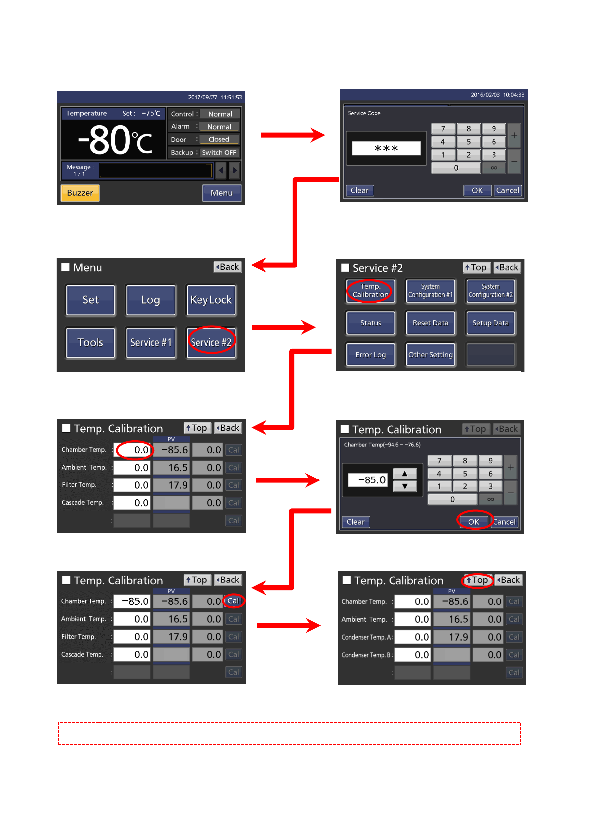
(Temperature calibration procedure:chamber sensor)
Cal key is vialed within setting range, touch
Cal key.
Move to Menu display, touch Service #2
key.
Move to Service display, touch Temp.
Calibration key
Move to input value display.
Input measured value by thermometer
Touch mark area.
Touch TOP key, so return to Menu display.
Input value area return to zero.
NOTE:: Ambient Temp. sensor and condenser A&B sensor can calibrate in the same procedure.
Keep touching MENU KEY (5 sec)
Move to Service Code input display,
so input “335232”
-43.3
-43.3
-43.3
-20-
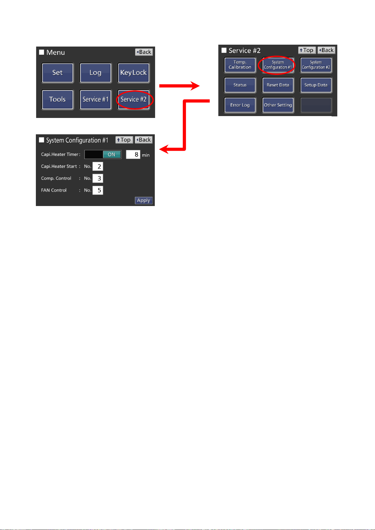
(Operation System Configuration #1)
■
Capi. Heater Timer
Slide key ON(enable),
setting time(Default 8 min).
Capi. Heater Start
Capi. heater control setting
(0) Heater on once in 18 hours
(1) Force on now
(2) Force off now(default)
Comp. Control
Compressor control setting
(0)Off
(1)On
(2)Auto(default)
(3)Manual
FAN control setting
(0) Off
(1) On
(2) Auto(default)
Refer to Control Specification for Capi. Heater Start,
Comp. Control, FAN Control.
Move to Menu display, touch Service #2 key.
Move to Service display, touch System
Configuration #1 key
-21-
 Loading...