

Panasonic MDF-DC700VX, MDF-DC500VX, MDF-DU900V, MDF-DU900VC Operating Instructions Manual
Please read the operating instructions carefully before using this product, and save the operating
instructions for future use.
See page 61 for all model numbers.
MDF-DC500VX
MDF-DC700VX
Series
O
perating Instructions
MDF-DC500VX
MDF-DC700VX
Ultra-Low Temperature Freezer
MDF-DC700VX

1
CONTENTS
INTRODUCTION P. 2
PRECAUTIONS FOR SAFE OPERATION P. 3
LABELS ON UNIT P. 7
SYMBOLS ON UNIT P. 7
ENVIRONMENTAL CONDITIONS P. 8
INTENDED USE AND PRECAUTIONS P. 8
FREEZER COMPONENTS
Unit P. 9
LCD touch panel P. 11
Remote alarm terminal P. 13
INSTALLATION
Installation site P. 14
Installation P. 15
START-UP OF UNIT P. 16
Operation during power failure P. 17
Operation after recovery from power failure P. 17
BASIC OPERATION ON LCD TOUCH PANEL P. 18
BASIC PARAMETERS
How to input numerical value and alphanumeric characters P. 19
Setting Temperature, High Alarm and Low Alarm P. 21
Setting operation control mode P. 22
Setting key lock P. 24
Removing key lock P. 26
ALARM PARAMETERS P. 27
OPERATION/ALARM LOG
Setting log interval P. 30
Displaying operation log P. 31
Exporting operation log P. 34
Displaying alarm log P. 37
Exporting alarm log P. 39
OTHER PARAMETERS
Setting date and time P. 42
Setting brightness and sleep P. 43
OPERATION MONITOR SYSTEM P. 45
ALARMS, SAFETY, AND SELF-DIAGNOSIS P. 46
ROUTINE MAINTENANCE P. 49
Cleaning of cabinet P. 49
Defrosting of chamber P. 50
CALIBRATION P. 50
REPLACEMENT OF WEAR-OUT PARTS
Replacing the battery for power failure alarm P. 51
Replacing the battery for backup cooling kit P. 51
TROUBLESHOOTING P. 52
DISPOSAL OF UNIT P. 53
Recycle of battery P. 53
TEMPERATURE RECORDER (OPTION) P. 58
BACKUP COOLING KIT (OPTION) P. 59
SPECIFICATIONS P. 60
PERFORMANCE P. 61
SAFETY CHECK SHEET P. 62
2
INTRODUCTION
■ Read the operating instructions carefully before using the appliance and follow the instructions for
safety operation.
■ Our company never guarantee any safety if the appliance is used for any objects other than intended
use or used by any procedures other than those mentioned in the operating instructions.
■ Keep the operating instructions in an adequate place to refer to it as necessary.
■ The contents of the operating instructions will be subjected to change without notice due to the
improvement of performance or functions.
■ Contact our sales representative or agent if any page of the operating instructions is lost or page order
is incorrect.
■ Contact our sales representative or agent if any point in the operating instructions is unclear or if there
are any inaccuracies.
■ No part of the operating instructions may be reproduced in any form without the expressed written
permission of our company.
CAUTION
Our company guarantees the product under certain warranty conditions. Our company in no
way shall be responsible for any loss of content or damage of content.
3
PRECAUTIONS FOR SAFE OPERATION
It is imperative that the user complies with the operating instructions
as it contains important safety advice.
Items and procedures are described so that you can use this unit correctly and safely.
If the precautions advised are followed, this will prevent possible injury to the user and
any other person.
Precautions are illustrated in the following way:
WARNING
Failure to observe WARNING signs could result in a hazard to personnel
possibly resulting in serious injury or death.
CAUTION
Failure to observe CAUTION signs could result in injury to personnel and
damage to the unit and associated property.
Symbol shows;
T
his symbol means caution.
This symbol means an action is prohibited.
This symbol means an instruction must be followed.
Be sure to keep the operating instructions in a place accessible to users of this unit.
NOTE:
As with any equipment that uses CO2 gas, there is a likelihood of oxygen depletion in the vicinity
of the equipment. It is important that you assess the work site to ensure there is suitable and
sufficient ventilation. If restricted ventilation is suspected, then other methods of ensuring a
safe environment must be considered. These may include atmosphere monitoring and
warning devices.

4
PRECAUTIONS FOR SAFE OPERATION
Do not use the unit outdoors. Current leakage or electric shock may result if the unit is exposed to
rain water.
Only qualified engineers or service personnel should install the unit. The installation by
unqualified personnel may cause electric shock or fire.
Install the unit on a sturdy floor and take an adequate precaution to prevent the unit from
turning over. If the floor is not strong enough or the installation site is not adequate, this may result
in injury from the unit falling or tipping over.
Never install the unit in a humid place or a place where it is likely to be splashed by water.
Deterioration of the insulation may result which could cause current leakage or electric shock.
Never install the unit in a flammable or volatile location. This may cause explosion or fire.
Never install the unit where acid or corrosive gases are present as current leakage or electric
shock may result due to corrosion.
Always ground (earth) the unit to prevent electric shock. If the power supply outlet is not
grounded, it will be necessary to install a ground by qualified engineers.
Never ground the unit through a gas pipe, water main, telephone line or lightning rod. Such
grounding may cause electric shock in the case of an incomplete circuit.
Connect the unit to a power source as indicated on the rating label attached to the unit. Use
of any other voltage or frequency other than that on the rating label may cause fire or electric shock.
Never store volatile or flammable substances in this unit if the cylinder cannot be sealed. These
may cause explosion or fire.
Do not insert metal objects such as a pin or a wire into any vent, gap or any outlet on the unit.
This may cause electric shock or injury by accidental contact with moving parts.
Use this unit in safe area when treating the poison, harmful or radiate articles. Improper use
may cause bad effect on your health or environment.
Turn off the power switch (if provided) and disconnect the power supply to the unit prior to any
repair or maintenance of the unit in order to prevent electric shock or injury.
Do not touch any electrical parts (such as power supply plug) or operate switches with a wet
hand. This may cause electric shock.
WARNING
5
Ensure you do not inhale or consume medication or aerosols from around the unit at the time of
maintenance. These may be harmful to your health.
Never splash water directly onto the unit as this may cause electric shock or short circuit.
Never put cylinders with liquid on the unit as this may cause electric shock or short circuit when
the liquid is spilled.
Never bind, process, or step on the power supply cord, or never damage or break the power
supply plug. A broken supply cord or plug may cause fire or electric shock.
Do not use the supply cord if its plug is loose. Such supply cord may cause fire or electric shock.
Never disassemble, repair, or modify the unit yourself. Any such work carried out by an
unauthorized person may result in fire, or electric shock or injury due to a malfunction.
Disconnect the power supply plug if there is something wrong with the unit. Continued
abnormal operation may cause electric shock or fire.
Do not position this unit and the other unit so that it is difficult to operate the disconnection of
the power supply plug. Failure to disconnect the power supply plug may cause fire if there is
something wrong with the unit.
When removing the plug from the power supply outlet, grip the power supply plug, not the cord.
Pulling the cord may result in electric shock or fire by short circuit.
Disconnect the power supply plug before moving the unit. Take care not to damage the power
cord. A damaged cord may cause electric shock or fire.
Disconnect the power supply plug when the unit is not used for long periods. Keeping the
connection may cause electric shock, current leakage, or fire due to the deterioration of insulation.
If the unit is to be stored unused in an unsupervised area for an extended period, ensure that
children do not have access and that doors cannot be closed completely with a key.
The disposal of the unit should be accomplished by appropriate personnel. Remove doors to
prevent accidents such as suffocation.
Do not put the packing plastic bag within reach of children as suffocation may result.
Flammable and explosive product. This product contains flammable refrigerant. Do not damage
or break the pipework.
Connect the power supply plug to the power source firmly after removing the dust on the plug.
A dusty plug or improper insertion may cause a heat or ignition.
WARNING
6
PRECAUTIONS FOR SAFE OPERATION
This unit must be plugged into a dedicated circuit protected by branch circuit breaker.
Use a dedicated power source as indicated on the rating label attached to the unit. A multiple-tap
may cause fire resulting from abnormal heating.
Never store corrosive substances such as acid or alkali in this unit if the container cannot be
sealed. These may cause corrosion of inner components or electric parts.
Check the setting when starting up of operation after power failure or turning off of power
switch. The stored items may be damaged due to the change of setting.
Be careful not to tip over the unit during movement to prevent damage or injury.
Prepare a safety check sheet (copy the last page) when you request any repair or maintenance for
the safety of service personnel.
CAUTION
7
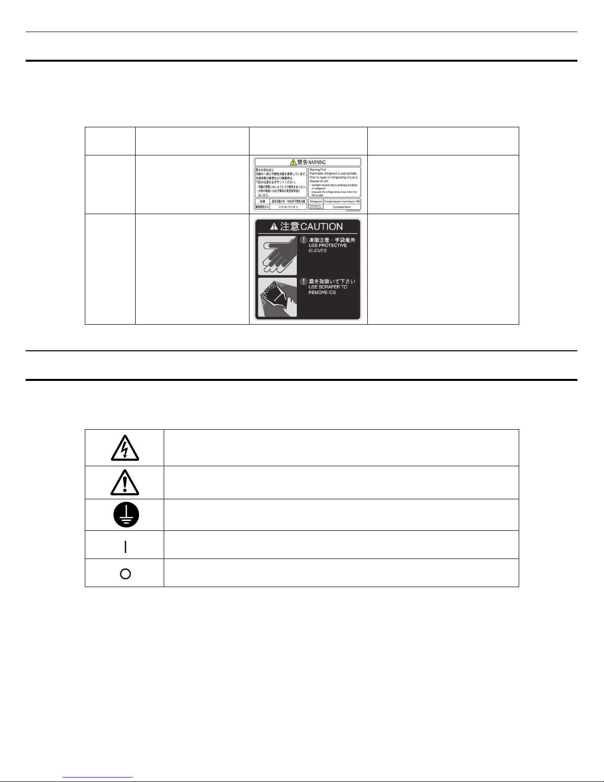
LABELS ON UNIT
Warning safety labels applied to the ultra-low temperature freezer.
Users are advised to avoid accidents by carefully reading the warnings and cautions contained on
warning labels at key locations on the interior and exterior of the ultra-low temperature freezer.
Possible
Danger
Warning/Caution Type
Location of Danger
Warning/Caution Label Description of Danger
Personal
injury
Environment
Refrigerating circuit
Warning fire.
Personal
injury
Frostbite and frost
Interior
Frostbite and frost caution label.
SYMBOLS ON UNIT
The symbols are attached to the ultra-low temperature freezer. The following table describes the
symbols.
This symbol is attached to covers that access high-voltage electrical components to
prevent electric shock. Only a qualified engineer or service personnel should be
allowed to open these covers.
This symbol indicates that caution is required. Refer to product documentation for
details.
This symbol indicates an earth.
This symbol means “ON” for a power switch.
This symbol means “OFF” for a power switch.

8
ENVIRONMENTAL CONDITIONS
This equipment is designed to be safe at least under the following conditions (based on the IEC 61010-1):
■ Indoor use;
■ Altitude up to 2000 m;
■ Ambient temperature 5
o
C to 40oC;
■ Maximum relative humidity 80% for temperature up to 31
o
C decreasing linearly to 50% relative humidity
at 40
o
C;
■ Mains supply voltage fluctuations up to ±10% of the nominal voltage;
■ Transient overvoltages up to the levels of OVERVOLTAGE CATEGORY II;
■ Temporary OVERVOLTAGES occurring on the mains supply;
■ Applicable pollution degree of the intended environment (POLUTION DEGREE 2 in most cases);
INTENDED USE AND PRECAUTIONS
This equipment is designed for low temperature storage of human cells, organs, plasma and DNAs.
■ The effective storage period depends on the sample condition and storage temperature. It is
necessary to determine the storage temperature and period suitable for the purpose.
■ For the live cells, the lower storage temperature should be required for long term storage. It is
recommended to store the live cells at -130
o
C or lower.
9
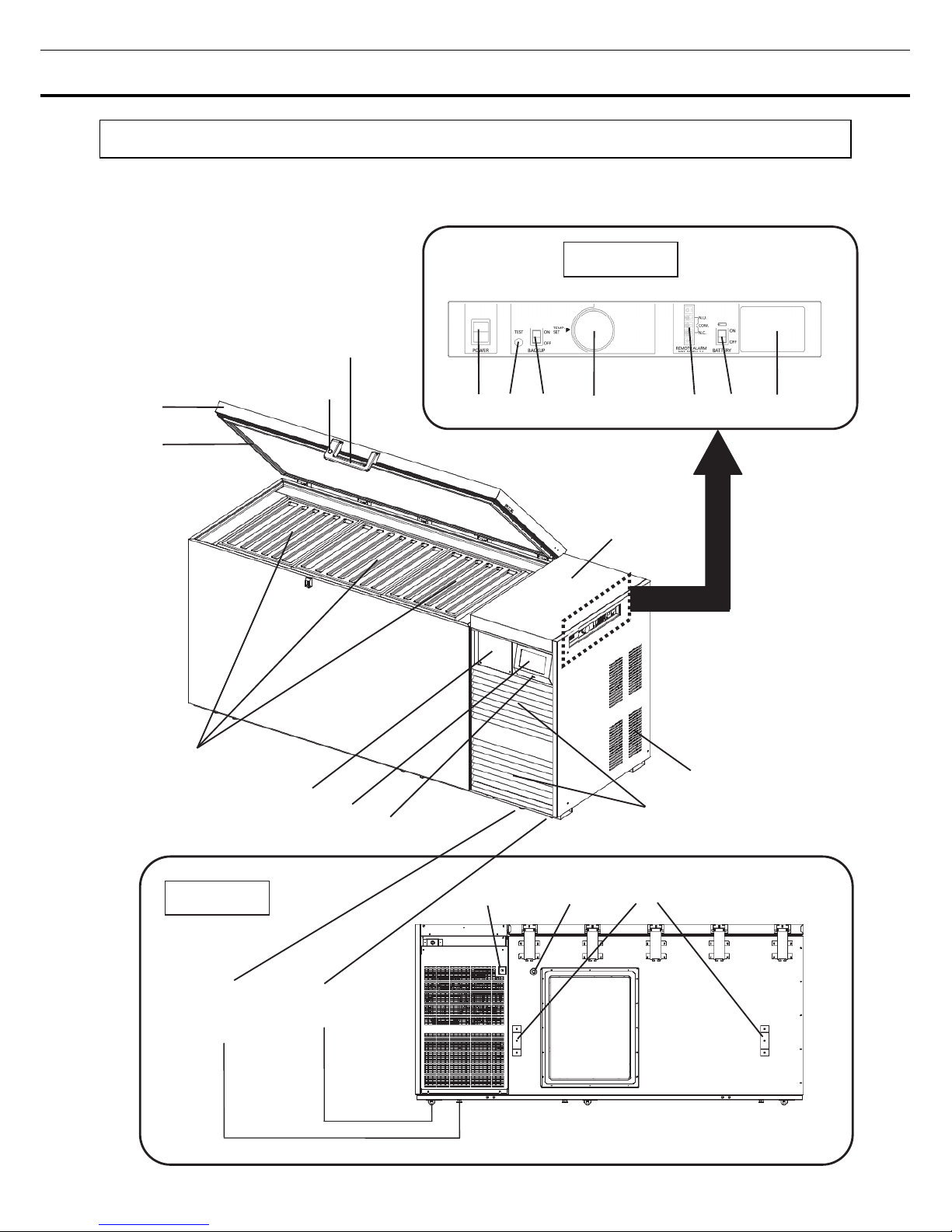
FREEZER COMPONENTS
Unit
The model below is the MDF-DC700VX. However, the MDF-DC500VX is also equivalent structures.
11 12 13
1
3
2
Caster
(6 pieces)
8
(3 pieces
on the front side
)
9
4
(3 pieces)
Back side
Handle
Side table
7
6
5
10
Right side
14 15* 16* 17*
18 19 20

10
FREEZER COMPONENTS
1. Keyhole: Turn clockwise to 180
o
with a key and the outer door is securely locked.
2. Door: Hinged type. The door can be opened in any angle on the way to full open.
3. Magnetic door gasket: Seals the door and prevents leakage of cold air.
4. Inner lid: Serves as a means of reducing cold air leakage when the door is open. Remove the frost
regularly (refer to page 50).
5. Space for temperature recorder: An optional automatic temperature recorder MTR-85H or
MTR-G85C can be attached here (refer to page 58). For the usage, refer to the INSTRUCTIONS FOR
USE enclosed with an optional temperature recorder.
6. LCD touch panel: Refer to page 11~12.
7. USB port: Insert USB memory to export operations and alarms log. Refer to page 34~41.
Note: It is impossible to use USB memory which is required password input.
8. Leveling feet: It is possible to adjust their length by turning them. When installing, lengthen the
leveling feet to steady the unit (refer to page 15).
9. Grille: Do not block this vent to keep the proper cooling performance.
10. Exhaust air vent: Be careful not to block this.
11. Backup cooling kit joint: When installing an optional backup cooling kit MDF-UB5, connect here the
pipelines from a liquid CO
2
cylinder (refer to page 59).
12. Access port: This is used for leading a cable and sensor of a measuring equipment to chamber.
Note: Re-install the access port cap and the insulating pad after use. Incomplete installation may cause
poor cooling or dew condensation outside the access port.
13. Fixture: 2 fixtures are provided as spacers between the cabinet and wall and also serve as hooks to
fix the unit (refer to page 15).
14. Power switch: Turn ON the power switch (ON-“l”, OFF-“○”).
15. Backup test switch (TEST)*: It is the switch to confirm that the backup cooling kit can inject liquid
CO
2
(refer to page 59).
16. Backup power switch (BACK UP)*: Power switch of the backup cooling kit (refer to page 59).
17. Temperature setting knob (TEMP. SET)*: It is the knob which adjusts injection set temperature of
the backup cooling kit (refer to page 59).
18. Remote alarm terminal: This terminal informs the alarm to remote location by connecting to external
alarm unit. Refer to page 13.
19. Battery switch for power failure alarm: Normally, turn ON this switch. Be sure to turn OFF this
switch if the unit is not in operating.
20. Communication box cover: An optional LAN interface board MTR-L03 or an optional interface board
MTR-480 can be attached here.
Note: For the data acquisition system MTR-5000 user only. Contact our sales representative or agent for
purchase.
* When an optional backup cooling kit MDF-UB5 is installed.
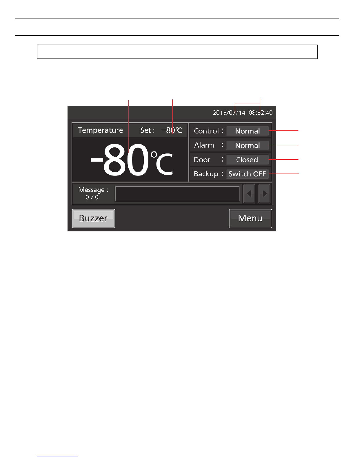
11
LCD touch panel
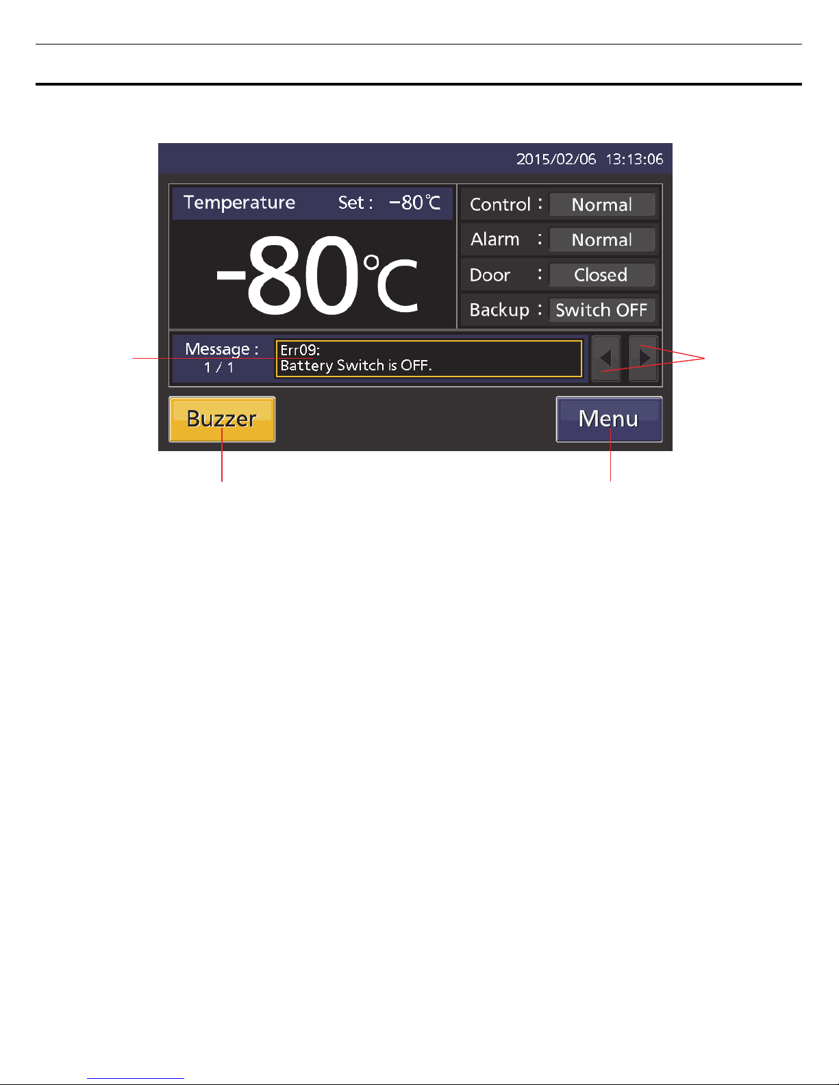
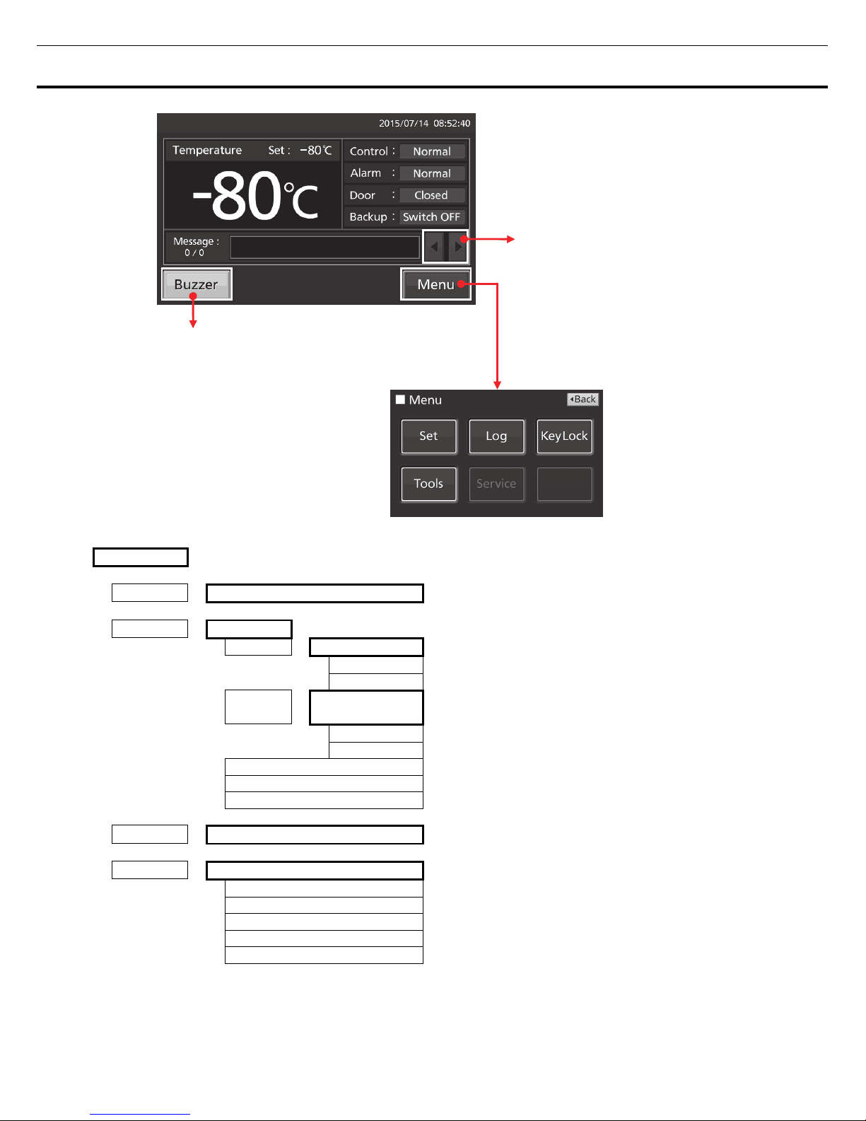
The following display (called the Top screen) will appear when the power switch is turned ON.
Note: It takes approximately 20 seconds until Top screen is displayed.
1 2 3
4
5
6
7
1. Present temperature display field: The current chamber temperature is displayed.
Note: An integer rounded off below a decimal point is displayed.
2. Set temperature value display field: The set value of chamber temperature is displayed. Default
setting: -80
o
C.
3. Present date/time display field: Normally, this indicator shows date and time. The date and time is
simply set when the freezer is shipped from the factory. Refer to page 42 for details.
4. Control display: The present operation control mode is displayed (refer to page 22~23 for setting).
Normal control: “Normal” is displayed.
Eco control: “ECO” is displayed.
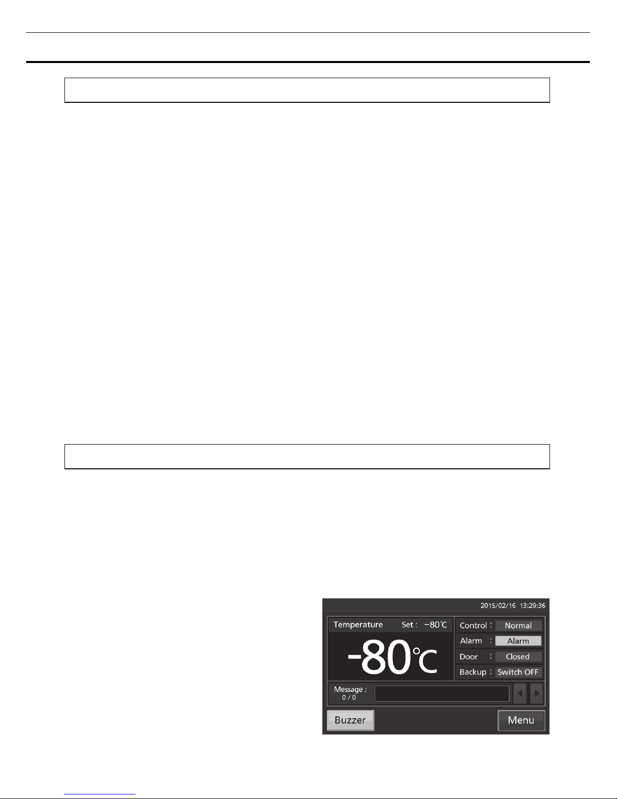
5. Alarm display: Refer to page 46~47 for details of alarms.
Normal condition: “Normal” is displayed.
Alarm-activated, buzzer-delayed: “Alarm” is displayed alternately in normal characters and reverse video.
Alarm-activated, buzzer-sounding: “Warning” is displayed alternately in normal characters and reverse video.
6. Door (opening/closing) display:
Open: “Open” is displayed alternately in normal characters and reverse video.
Close: “Closed” is displayed.
7. Backup display: (It is displayed only when an optional backup cooling kit MDF-UB5 is installed)
ON/OFF of the backup power switch is displayed (refer to page 59).
ON: “Switch ON” is displayed.
OFF: “Switch OFF” is displayed.
12
FREEZER COMPONENTS
8
11 10
8. Message display field: The information of the operation monitor system, alarms or errors are
displayed when fault occurs. Refer to page 45~47.
9. Message select key: When there are a number of alarm, errors or information of the operation monitor
system, the message on the screen is changeable.
10. Menu key: Press this key to lead the Menu screen. It is possible to set various setting on the Menu
screen. Refer to page 18.
11. Buzzer key: Press this key to silence the buzzer. However, when the ring back is ON, the buzzer will
sound again when the ring back passed and the alarm state still continues. Refer to page 28 and 48.
9
13
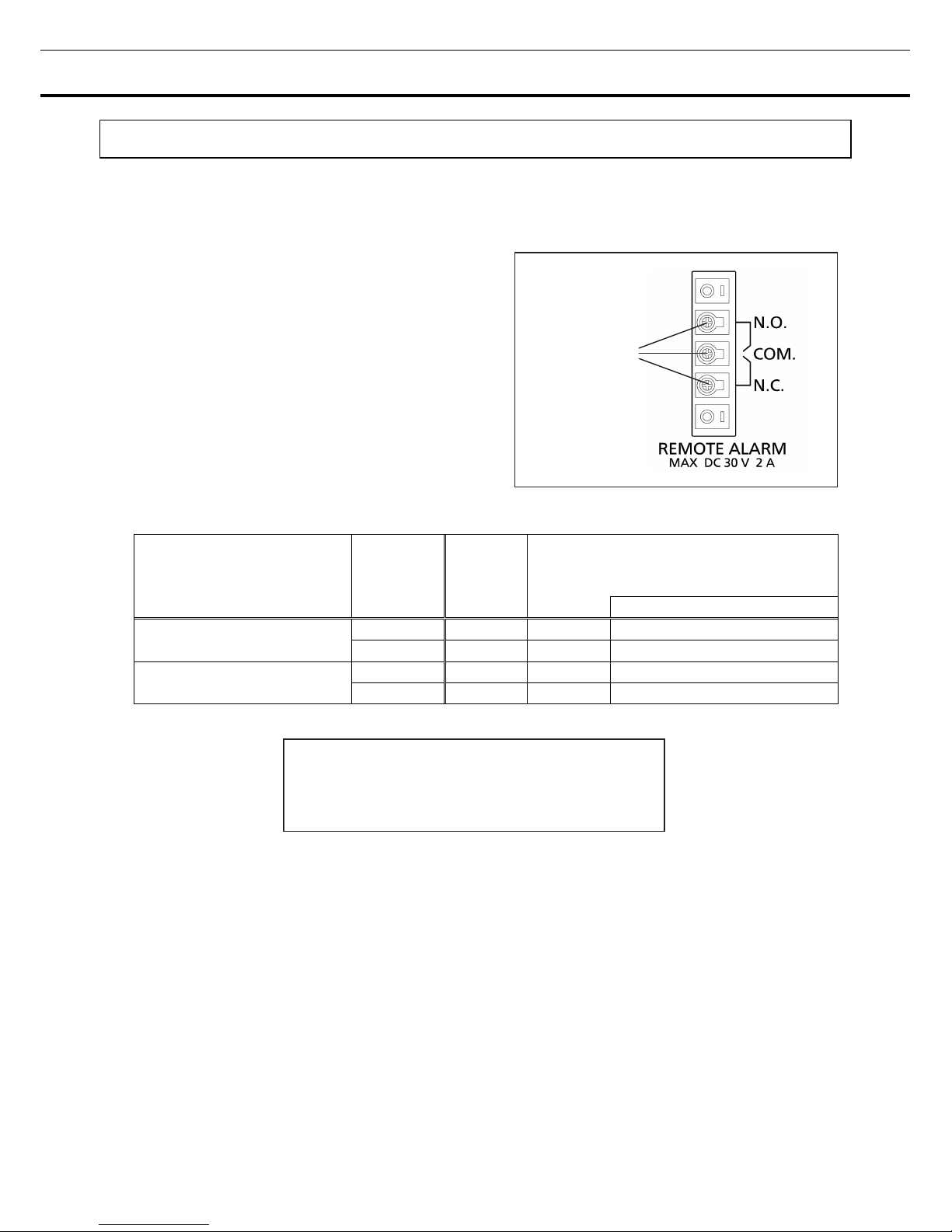
Remote alarm terminal
The alarm of this unit can be informed at a remote location from this unit by connecting the external alarm
device to the remote alarm terminals. For the type and behavior of remote alarm output, refer to page 46
~47.
The terminal of the remote alarm is installed at the
right side of the unit (See the figure on the point).
The alarm is outputted from this terminal. Contact
capacity is DC 30 V, 2 A.
When Buzzer key is pressed, the behavior of the
remote alarm is showed in Table.1.
Note: In the door alarm, the remote alarm does not
work. Refer to page 46.
Table 1 The behavior of the remote alarm when pressing Buzzer key
Remote Alarm setting
(Refer to page 27~29)
Connecting
terminal
Normal
condition
Abnormal condition
(Including in the cases of power outage and
of where the power plug is pulled out.)
When pressing Buzzer key
ON:
Non-interlock with Buzzer key
COM.-N.C. Close Open Open (Maintain in abnormality)
COM.-N.O. Open Close Close (Maintain in abnormality)
OFF:
Interlock with Buzzer key
COM.-N.C. Close Open Close (Return to normal)
COM.-N.O. Open Close Open (Return to normal)
Use a twisted sealed wire for the connection.
Type; UL 2343, UL 2448, UL 2464, UL2552, UL2623.
Length: 30 m max.
Remote alarm
terminal
14
INSTALLATION
Installation site
To operate this unit properly and to obtain maximum performance, install the unit in a location with the
following conditions:
■ A location not subjected to direct sunlight
Do not install the unit under direct sunlight. Installation in a location subjected to direct sunlight cannot
obtain the intended performance.
■ A location with adequate ventilation
Leave at least 10 cm around the unit for ventilation. Poor ventilation will result in a reduction of the
performance and consequently the failure.
■ A location away from heat generating sources
Avoid installing the unit near heat-emitting appliances such as a heater or a boiler etc. Heat can decrease
the intended performance of the unit.
■ A location with little temperature change
Install the unit under stable ambient temperature. The allowable ambient temperature is between +5
o
C
and +30
o
C.
■ A location with a sturdy and level floor
Always install the unit on a sturdy and level floor. The uneven floor or tilted installation may cause failure
or injury. Install the unit in stable condition to avoid the vibration or noise. Unstable condition may cause
vibration or noise.
WARNING
Install the unit on a sturdy floor. If the floor is not strong enough or the installation site is not
adequate, this may result in injury from the unit falling or tipping over.
Select a level and sturdy floor for installation. This precaution will prevent the unit from tipping.
Improper installation may result in water spillage or injury from the unit tipping over.
■ A location not prone to high humidity
Install the unit in the ambient of 80 %R.H. or less humidity. Installation under high humidity may cause
current leakage or electric shock.
WARNING
Do not use the unit outdoors. Current leakage or electric shock may result if the unit is exposed to
rain water.
Never install the unit in a humid place or a place where it is likely to be splashed by water.
Deterioration of the insulation may result which could cause current leakage or electric shock.
■ A location without flammable or corrosive gas
Never install the unit in a location where it will be exposed to inflammable or corrosive gas. This may
cause explosion or fire or may result in the current leakage or electric shock by the corrosion of the
electrical components.

15
■ A location without corrosive substance
Never install the unit in a location where corrosive substance such as sulfur-contained compound may
generate (ex. near a sink). The corrosion of copper pipe of the cooling circuit may result in the failure of
the unit.
■ A location without the possibility of anything fall
Avoid installing the unit in the location where anything can fall down onto the unit. This may cause the
breakdown or failure of the unit.
Installation
1. Remove the packaging materials and tapes
Remove all transportation packaging materials and tapes. Open the doors and ventilate the unit. If the
outside panels are dirty, clean them with a diluted neutral dishwashing detergent (Undiluted detergent can
damage the plastic components. For the dilution, refer to the instruction of the detergent). After the
cleaning with the diluted detergent, always wipe it off with a wet cloth. Then wipe off the panels with a dry
cloth.
Note: Remove the cable tie banding the power supply cord. Prolonged banding may cause the corrosion
of the cord coating.
2. Adjust the leveling feet
It is possible to adjust the length of the leveling feet
by turning them (Fig.1). Lengthen the leveling feet
until the casters are lifted from the floor, and let 3
leveling feet support the front side of this unit. After
that, adjust 3 leveling feet to steady this unit.
3. Fix the unit
Two fixtures are attached to the rear of the frame.
Fix the frame to the wall with these fixtures and rope
or chain.
4. Installation branch circuit breaker
This unit is to be connected to a dedicated circuit protected by branch circuit breaker.
Contact our sales representative or agent.
WARNING
Use a power supply outlet with ground (earth) to prevent electric shock. If the power supply outlet is
not grounded, it is necessary to install a ground by qualified engineers.
Never ground the unit through a gas pipe, water main, telephone line or lightning rod. Such
grounding may cause electric shock in the case of an incomplete circuit.
Fig. 1
Leveling fee
t
Shrink
Lengthen

16
START-UP OF UNIT
Follow the procedures for the initial and consequent operations of the unit.
1. Make sure that both of the power switch and the battery switch for power failure alarm are OFF (factory
setting is OFF).
Note: When the power switch is ON and the battery switch for power failure alarm is ON, the power
failure alarm is activated (refer to page 46).
2. (When an optional backup cooling kit MDF-UB5 is installed) Turn OFF the backup power switch.
3. Before putting some contents to cryopreserve into the chamber, connect the power supply cord to the
outlet.
4. Turn ON the power switch to start operation of the unit.
5. Turn ON the battery switch for power failure alarm.
Note: When the battery switch for power failure alarm is OFF, “Err09: Battery Switch is OFF.” is displayed
in the message display field. By turning ON the battery switch for power failure alarm, this message
disappears.
6. Set the chamber temperature and the high/low alarm (refer to page 21~22).
Note: Keep the ambient temperature between 5
o
C to 30 oC. The chamber temperature may not reach
set temperature when the ambient temperature is higher than 30
o
C.
7. Make sure that chamber temperature is cooled to the set temperature.
8. Do the alarm test. Make sure that the buzzer sounds by pressing Buzzer key for 5 seconds. Press
Buzzer key again to stop the buzzer and the alarm test finishes.
9. (When an optional backup cooling kit MDF-UB5 is installed) After the chamber temperature reaches
the set temperature, turn ON the backup power switch.
Note: When operating this unit for the first time or after not using it for an extended period of time, it is
required 3 days (72 hours) operation of unit before using the backup cooling kit. The capacity of internal
battery for backup cooling kit may be less or flat by electric discharge.
10. (When an optional backup cooling kit MDF-UB5 is installed) Set the injection set temperature of the
backup cooling kit by adjusting the temperature setting knob.
11. Put the contents to cryopreserve into the chamber.
Note:
・Do not put a large amount of contents to cryopreserve at a time. Put little by little to prevent rapid rise of
the chamber temperature.
・Do not put a large amount of warm contents to cryopreserve. The rise of the chamber temperature may
have a bad influence on the contents in the unit.
・This unit is designed only for low temperature storage of medical/biotechnology samples (ex. cells) or
reagents. Do not use for the purpose other than above (ex. freezing of regenerating agent).
・In case some optional inventory racks are in the chamber, be careful not to drop inventory rack when
pulling out it.
17
Operation during power failure
When the battery switch for power failure is ON, during a power failure the behavior of this unit is as
follows.
●The power failure alarm is activated (refer to page 46).
Press Buzzer key to silence the buzzer of the power failure alarm. In case the ring back is turned ON,
buzzer sounds again when a power failure still continues after ring back set time passed (refer to page
28).
●LCD touch panel is turn OFF (refer to page 46).
By touching the LCD touch panel, it lights in the set brightness for 5 seconds.
●The High/Low Alarm is ready to activate during a power failure (refer to page 21~22 and 46).
(While the LCD touch panel is lighting after touching) The message of the High/Low Alarm is displayed in
the message display field, and “Alarm” (or “Warning”) is displayed alternately in normal characters and
reverse video in the alarm display. The buzzer and the remote alarm (although it is of the power failure
alarm) are already activated.
●The clock function does not stop.
●Operation log data and alarm log data during a power failure is saved.
Note: When the capacity of the battery for power failure alarm is flat during a power failure, subsequent
operation log data and alarm log data is not saved.
Operation after recovery from power failure
The set value is memorized by nonvolatile memory. Accordingly, the chamber resumes the operation with
setting before power failure.
Note:
・It may take up to 1 minute until the LCD touch panel lights after recovery from power failure.
・All products start at the same time as the recovery from the power failure, so that, the temporary voltage
drop may have a bad influence on the starting of this unit. To prevent this situation, set the appropriate
compressor delay time of this unit (refer to page 23).
Although the power failure alarm is canceled at the
recovery of the power failure, in order to remind
that power failure had happened, buzzer is
sounding and “Alarm” is displayed alternately in
normal characters and reverse video in the alarm
display (refer to page 48). By pressing Buzzer key,
the alarm display returns to “Normal” and the
buzzer stops.
Note: It is possible to confirm the past alarms in
the “Displaying alarm log” (refer to page 37~38).
18
BASIC OPERATION ON LCD TOUCH PANEL
◆Message select key:
(Operate) Changing some messages
◆Buzzer key: (Operate) Silencing the buzzer
(Alarm is not canceled except for some alarms; page 48)
●Operation from Menu key
■Menu screen
Page
◆Set
→
■Temp. Setting screen
(Setting) Temp., High Alarm, Low Alarm
21~22
◆Log
→
■Log screen
◆Chart
→
■Chart screen
◆Actual Temp.
(Display) Chamber temp. log graph (can be exported)
31~33
◆Door Opening
(Display) Door opening log graph (can be exported)
31~33
◆Data
Export
→
■Export screen
◆Actual Temp.
(Export) Chamber temperature log
34~36
◆Door Opening
(Export) Door opening log
34~36
◆Setting
(Setting) Log interval, Unique ID
30~31
◆Alarm
(Display)Alarm log (can be exported)
37~38
◆Alarm Export
(Export) Alarm log
39~41
◆Key Lock
→
■Key Lock screen
(Setting) Key lock ON/OFF, password
24~26
◆Tools
→
■Tools screen
◆Operation Setting
(Setting) Eco operation ON/OFF, comp. delay time
22~23
◆Alarm Setting
(Setting)Alarm delay, ring back, remote alarm etc
27~29
◆DAQ Setting
Do not press (It is not possible to set.)
◆Date & Time
(Setting) Date, time 42
◆Brightness/Sleep
(Setting) Brightness, sleep ON/OFF etc
43~44
19
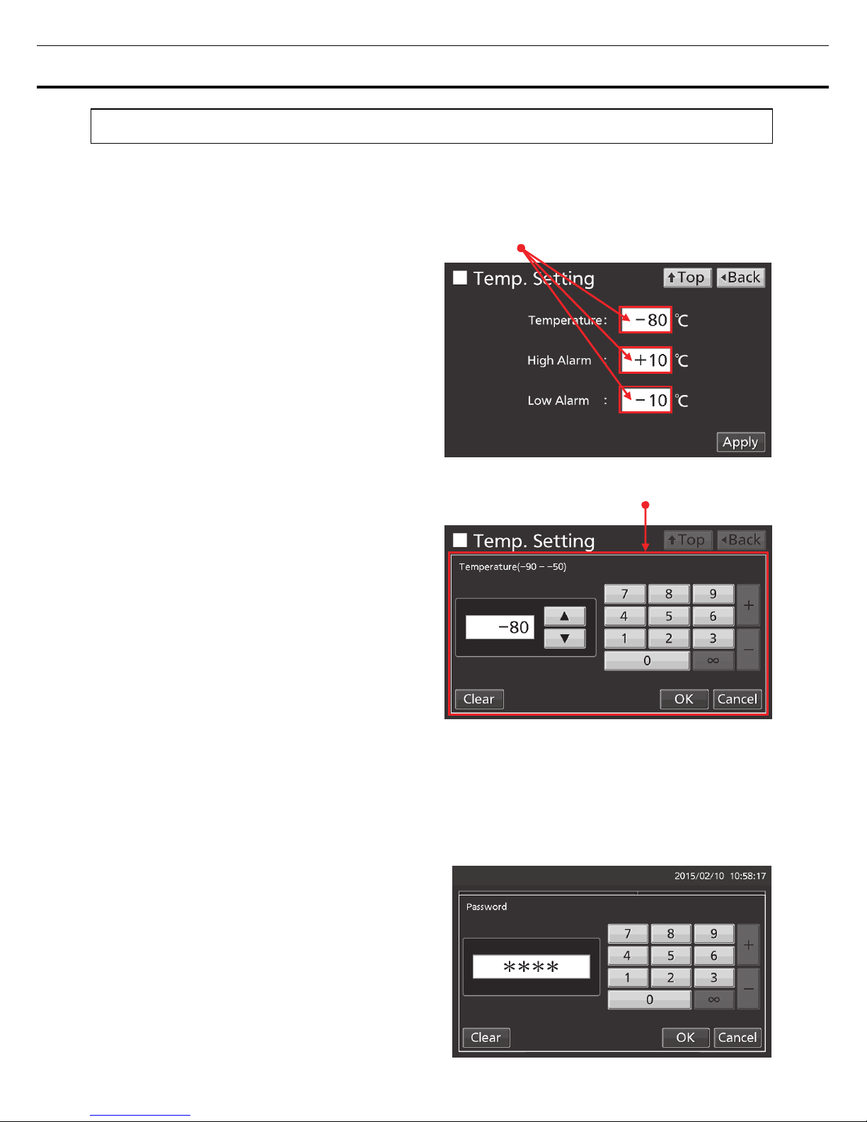
BASIC PARAMETERS
How to input numerical value and alphanumeric character
On each screen in the LCD touch panel, it may be necessary to input numerical value or alphanumeric
characters.
●When inputting numerical value
1. By pressing numeric input box, numeric input
window is displayed.
2. Press Numeric key or Up/Down key to input
numerical value, and press OK key.
●Key description
・Numeric key (0~9): Input numerical value.
・Up/Down key (▲/▼): Increases or decreases the numerical value displayed in the numeric input box.
・Clear key: Deletes the numerical value displayed on the numeric input box.
・Cancel key: Stops inputting on the numeric input box and closes the input window.
Note: Up/Down key may not be displayed.
Numeric input box
Numeric input window
 Loading...