

Panasonic MDF-594, MDF-794, MDF-594AT, MDF-794AT Operating Instructions Manual

Please read these instructions carefully before using this product, and save this operating instructions
for future use.
See page 32 for all Model Numbers.
MDF-594
MDF-794
Series
MDF-594
MDF-594AT
MDF-794
MDF-794AT
Ultra-Low Temperature Freezer
Operating Instructions
MDF-594AT

1
CONTENTS
INTRODUCTION P. 2
PRECAUTIONS FOR SAFE OPERATION P. 3
ENVIRONMENTAL CONDITIONS P. 7
FREEZER COMPONENTS P. 8
Control panel P. 10
INSTALLATION SITE P. 11
INSTALLATION P. 12
START-UP OF UNIT P. 13
CHAMBER TEMPERATURE SETTING P. 14
ALARM TEMPERATURE SETTING P. 15
SETTING OF ALARM RESUME TIME P. 16
REMOTE ALARM TERMINAL P. 17
ALARMS AND SAFETY FUNCTIONS P. 17
TEMPERATURE RECORDER (AT type) P. 19
BACKUP COOLING KIT (AT type) P. 21
ROUTINE MAINTENANCE P. 22
Cleaning of cabinet P. 22
Cleaning of condenser filter P. 22
Defrosting of inside wall P. 22
TROUBLESHOOTING P. 23
DISPOSAL OF UNIT P. 24
Recycle of battery P. 24
Decontamination of unit P. 24
DISPOSAL OF BATTERY P. 29
SPECIFICATIONS P. 30
PERFORMANCE P. 32
SAFETY CHECK SHEET P. 33
2
INTRODUCTION
Read this operating instructions carefully before using the appliance and follow the instructions for
safety operation.
Our company never guarantee any safety if the appliance is used for any objects other than intended
use or used by any procedures other than those mentioned in this operating instructions.
Keep this operating instructions in an adequate place to refer to it as necessary.
The contents of the operating instructions will be subjected to change without notice due to the
improvement of performance or functions.
Contact our sales representative or agent if any page of the operating instructions is lost or page order
is incorrect.
Contact our sales representative or agent if any point in this operating instructions is unclear or if there
are any inaccuracies.
No part of this operating instructions may be reproduced in any form without the expressed written
permission of our company.
CAUTION
Our company guarantees the product under certain warranty conditions. Our company in no
way shall be responsible for any loss of content or damage of content.
3
PRECAUTIONS FOR SAFE OPERATION
It is imperative that the user complies with this operating instructions
as it contains important safety advice.
Items and procedures are described so that you can use this unit correctly and safely.
If the precautions advised are followed, this will prevent possible injury to the user and
any other person.
Precautions are illustrated in the following way:
WARNING
Failure to observe WARNING signs could result in a hazard to personnel
possibly resulting in serious injury or death.
CAUTION
Failure to observe CAUTION signs could result in injury to personnel and
damage to the unit and associated property.
Symbol shows;
this symbol means caution.
this symbol means an action is prohibited.
this symbol means an instruction must be followed.
Be sure to keep this operating instructions in a place accessible to users of this unit.
< Label on the unit >
This mark is labeled on the cover in which the electrical components of high voltage
are enclosed to prevent the electric shock.
The cover should be removed by a qualified engineer or a service personnel only.
WARNING
As with any equipment that uses CO2 gas, there is a likelihood of oxygen depletion in the vicinity
of the equipment. It is important that you assess the work site to ensure there is suitable and
sufficient ventilation. If restricted ventilation is suspected, then other methods of ensuring a
safe environment must be considered. These may include atmosphere monitoring and
warning devices.
4
PRECAUTIONS FOR SAFE OPERATION
Do not use the unit outdoors.
Current leakage or electric shock may result if the unit is exposed to
rain water.
Only qualified engineers or service personnel should install the unit.
The installation by
unqualified personnel may cause electric shock or fire.
Install the unit on a sturdy floor and take an adequate precaution to prevent the unit from
turning over.
If the floor is not strong enough or the installation site is not adequate, this may result
in injury from the unit falling or tipping over.
Never install the unit in a humid place or a place where it is likely to be splashed by water.
Deterioration of the insulation may result which could cause current leakage or electric shock.
Never install the unit in a flammable or volatile location.
This may cause explosion or fire.
Never install the unit where acid or corrosive gases are present
as current leakage or electric
shock may result due to corrosion.
Always ground (earth) the unit to prevent electric shock.
If the power supply outlet is not
grounded, it will be necessary to install a ground by qualified engineers.
Never ground the unit through a gas pipe, water main, telephone line or lightning rod.
Such
grounding may cause electric shock in the case of an incomplete circuit.
Connect the unit to a power source as indicated on the rating label attached to the unit.
Use
of any other voltage or frequency other than that on the rating label may cause fire or electric shock.
Never store volatile or flammable substances
in this unit if the container cannot be sealed. These
may cause explosion or fire.
Do not insert metal objects such as a pin or a wire into any vent, gap or any outlet on the unit.
This may cause electric shock or injury by accidental contact with moving parts.
Use this unit in safe area when treating the poison, harmful or radiate articles.
Improper use
may cause bad effect on your health or environment.
Turn off the power switch (if provided) and disconnect the power supply to the unit prior to any
repair or maintenance
of the unit in order to prevent electric shock or injury.
Do not touch any electrical parts (such as power supply plug) or operate switches with a wet
hand.
This may cause electric shock.
WARNING
5
PRECAUTIONS FOR SAFE OPERATION
Ensure you do not inhale or consume medication or aerosols
from around the unit at the time of
maintenance. These may be harmful to your health.
Never splash water directly onto the unit
as this may cause electric shock or short circuit.
Never put containers with liquid on the unit
as this may cause electric shock or short circuit when
the liquid is spilled.
Never bind, process, or step on the power supply cord, or never damage or break the power
supply plug.
A broken supply cord or plug may cause fire or electric shock.
Do not use the supply cord if its plug is loose.
Such supply cord may cause fire or electric shock.
Never disassemble, repair, or modify the unit yourself.
Any such work carried out by an
unauthorized person may result in fire, or electric shock or injury due to a malfunction.
Disconnect the power supply plug if there is something wrong with the unit.
Continued
abnormal operation may cause electric shock or fire.
When removing the plug from the power supply outlet, grip the power supply plug,
not the cord.
Pulling the cord may result in electric shock or fire by short circuit.
Disconnect the power supply plug
before moving the unit. Take care not to damage the power
cord. A damaged cord may cause electric shock or fire.
Disconnect the power plug when the unit is not used for long periods.
Keeping the connection
may cause electric shock, current leakage, or fire due to the deterioration of insulation.
If the unit is to be stored unused in an unsupervised area for an extended period,
ensure that
children do not have access and that doors cannot be closed completely.
The disposal of the unit should be accomplished by appropriate personnel.
Remove doors to
prevent accidents such as suffocation.
Do not put the packing plastic bag within reach of children
as suffocation may result.
WARNING
6
PRECAUTIONS FOR SAFE OPERATION
Use a dedicated power source
(a dedicated circuit with a breaker) as indicated on the rating label
attached to the unit. A branched circuit may cause fire resulting from abnormal heating.
Connect the power supply plug to the power source firmly after removing the dust on the plug.
A dusty plug or improper insertion may cause a heat or ignition.
Never store corrosive substances such as acid or alkali
in this unit if the container cannot be
sealed. These may cause corrosion of inner components or electric parts.
Check the setting when starting up of operation after power failure or turning off of power
switch.
The stored items may be damaged due to the change of setting.
Be careful not to tip over the unit
during movement to prevent damage or injury.
Prepare a safety check sheet
when you request any repair or maintenance for the safety of service
personnel.
CAUTION

7
ENVIRONMENTAL CONDITIONS
This equipment is designed to be safe at least under the following conditions (based on the IEC61010-1):
Indoor use;
Altitude up to 2000 m;
Ambient temperature 5oC to 40oC;
Maximum relative humidity 80% for temperature up to 31oC decreasing linearly to 50% relative humidity
at 40
o
C;
Mains supply voltage fluctuations up to ±10% of the nominal voltage;
Transient overvoltages up to the levels of OVERVOLTAGE CATEGORY II;
Temporary OVERVOLTAGES occurring on the mains supply;
Applicable pollution degree of the intended environment (POLUTION DEGREE 2 in most cases)
8
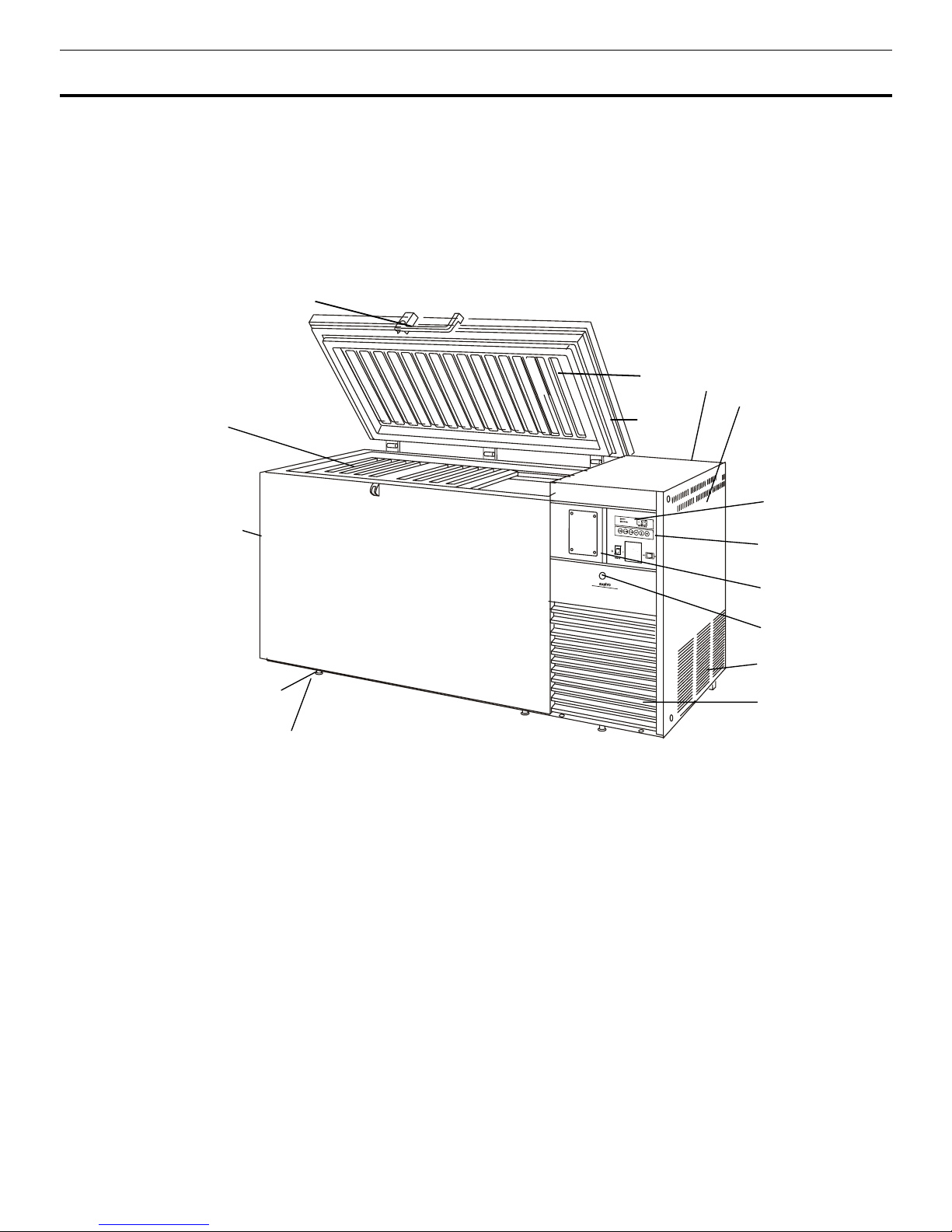
FREEZER COMPONENTS
MDF-594
1
3
13
7
8
12
11
10
4
2
9
6
5
14
14

9
FREEZER COMPONENTS
1. Lock
2. Door:
Hinged type. The door can be opened in any angle on the way to full open.
3. Magnetic door gasket:
Seals the door and prevents leakage of cold air.
4. Inner lid:
Serves as a means of reducing cold air leakage when the door is open. Remove the frost
before it is accumulated too much.
5. Access port:
Serves a means of leading the measuring cable from the freezing room to the outside.
6. Caster:
4 casters are provided. They make the moving of the unit easier.
7. Leveling foot:
Serves to adjust the height and to settle the frame.
8. Temperature display area:
The digital temperature indicator, alarm lamp, and filter check lamp are
installed.
9. Exhaust air vent:
Be careful not to block this.
10. Control panel cover
11. Control panel cover lock:
To lock the control panel cover to avoid the setting by accidental
contact.
12. Control panel:
Temperature set key, power switch and so on are installed.. Refer to page 10 for
details.
13. Backup cooling kit joint (rear side):
It is positioned at rear of the unit. Serves to connect with the
pipelines from the liquid CO
2
cylinder.
14. Side panel:
15. Air intake vent (grille):
Do not block this vent to keep the proper cooling performance.
10
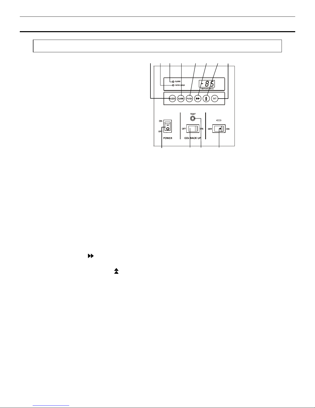
FREEZER COMPONENTS
Control panel
1. Power switch (POWER):
Power all functions except remote alarm and Backup cooling kit for AT
type.
2. CO2 Backup switch (CO2 BACK UP):
AT type only.
3. CO2 Backup test switch (TEST):
AT type only.
4. Battery switch:
It is the switch of the battery for the power failure alarm. Turn it on usually. Turn
it off when you do not drive for a long time. (More than 1 month).
5. Mode setting key. (PV/SV):
This key has functions.
PV: Present freezer compartment temperature is displayed.
SV: Setting temperature is displayed.
When the desired temperature is set, this key should be
pressed (SV side). The temperature setting can be done by using (6),(7),(8), keys, initial setting
temperature is -80oC.
6. Digit shift key ( ):
The digit of the figure displayed for temperature adjustment can be shifted
using this key.
7. Numerical value shift key ( ):
The figure that is displayed digitally can be changed by pressing
this key.
8. Enter key (ENT):
By pressing this key in set mode, the setting is memorized and set mode is
completed.
9. Alarm test key (ALARM):
Check that the alarm lamp and the buzzer are functional when the
freezer is operating well.
10. Alarm buzzer stop key (BUZZER):
To stop the alarm from sounding, press this key. Should a
further abnormality occur, the buzzer will sound automatically.
11. Alarm lamp (ALARM) and buzzer:
They operate in the following cases:
a)
Break down or power failure at the power supply.
- Alarm lamp blinks, buzzer sounds.
b)
Temperature rises about 10oC higher than the setting temperature.
- Alarm lamp blinks, buzzer sounds about 12 minutes later.
12. Filter check lamp (FILTER CHECK):
This lamp brinks and buzzer sound when the condenser
filter is clogged. Clean the condenser filter according to page 22 “Cleaning of condenser filter”.
MDF-594AT/ 794AT
8
1 2
3
4
1
07695
12 11
 Loading...