

Page 1
AC Servo Motor Driver
MINAS S-series
Operating Manual
Be sure give this instruction manual to the user.
• Thank you very much for your buying Panasonic AC Servo Motor Driver,A-series.
• Before use, read through this manual to ensure proper use. Keep this manual at an easily
accessible place so as to be referred anytime as necessary.
Page 2

Table of Contents
Before Use
Safety Precautions
•••••4
Introduction •••••••••••••8
After Opening the Package•••••••••••••••• 8
Check the Model Number of Amplifier ••••••••••••••••••
Check the Model Number of Motor •••••••••••••••••••
Check the Combination of Amplifier and Motor •••••••••••••••••••••
8
9
10
Preparations
and Adjustments
System Configuration and Wiring •••••
General Wiring Diagram
List of Available Components
Main Circuits ••••••••••••••••••••••••••••••• 22
CN SIG Connector
For Encoder ••••••••••••••••••••••••••••• 23
CN SER Connector ••••••••••••••••••••••• 24
CN I/F Connector
For Controller •••••••••••••••••••••••••••• 25
CN MON Connector ••••••••••••••••••• 35
Parameter Setting
Overview •••••••••••••••••••••••••••••••••••• 36
Parameter Groups and Listing
Setting the Parameters ••••••••••••••••••• 41
Overview of PANATERM
How to Connect•••••••••••••••••••••••••••• 41
••••••••••••••••••••••• 18
•••••••••••••••••• 20
•••••••••••36
••••••••••••••• 36
••••••••••••••• 41
“
18
Parts Description
Amplifier ••••••••••••••••••••••••••••••••••••• 12
Motor ••••••••••••••••••••••••••••••••••••••••• 13
•••••••••••12
Installation •••••••••••••••••14
Amplifier ••••••••••••••••••••••••••••••••••••• 14
Motor ••••••••••••••••••••••••••••••••••••••••• 16
Trial Run •••••••••••••••••••44
Inspections before Trial Run
Operation with
CN I/F Connected •••••••••••••••••• 45
••••••••••••••••••• 44
Adjustments•••••••••••••••50
Purposes of Gain Adjustments
Types of Gain Adjustments •••••••••••••• 50
How to Adjust Gain •••••••••••••••••••••••• 52
How to Use
"Normal Auto-Gain" Tuning
How to Use "Real Time
Auto-Gain" Tuning •••••••••••••••• 54
How to Adjust Gain Manually
Gain Tuning Using
Gain Adjustment Rotary Switch
To reduce the mechanincal
resonance
••••••••••••••••••••••••••• 59
••••••••••••••• 50
•••••••••• 53
••••••••••••••• 55
••••••••• 58
- 2 -
Page 3

Important Information
Protective Functions •••••••••••
60
Maintenance and
Inspections ••••••••••• 6 6
Appendixes
Conformance to EC Directives and UL Standards
Holding Brake ••••••••••••••••••••••••• App. 6
Dynamic Brake•••••••••••••••••••••••• App. 8
Timing Chart ••••••••••••••••••••••••• App. 10
Acceptable Loads on Output Shaft •••••••••••••••
Homing Operation (Precautions) ••••••••••••••
••••••••••• App. 2
App. 14
App. 15
Troubleshooting
••••••••••••••••••••••••••••••68
After-Sale Service
•••••••••••••••••••••• Back cover
Details of Parameters ••••••••••••• App. 16
Optional Parts ••••••••••••••••••••••• App. 38
Recommended Parts •••••••••••••• App. 47
Dimensions •••••••••••••••••••••••••• App. 48
Characteristics •••••••••••••••••••••• App. 53
Specifications ••••••••••••••••••••••• App. 54
- 3 -
Page 4
Safety Precautions
Observe the following precautions in order to avoid injuries of operators and other persons, and mechanical damages.
The following DANGER and CAUTION symbols are used according to the level of dangers possibly occur-
ring if you fail to observe the instructions or precautions indicated.
(Important)
DANGER
CAUTION
The following symbols indicate what you are not allowed to do, or what you
must observe.
Indicates a potentially hazardous situation which, if not
avoided, will result in death or serious injury.
Indicates a potentially hazardous situation which, if not avoided,
will result in minor or moderate injury and physical damage.
This symbol indicates that the operation is prohibited.
This symbol indicates that the operation must
be performed without fail.
DANGER
An over-current protection, earth leakage
breaker, over-temperature protection and
emergency stop should be installed.
Failure to observe this
instruction could result in electric
shocks, injuries and/or fire.
Don't insert your hands in
the amplifier.
Failure to observe this
instruction could result in
burns and/or electric shocks.
Install the amplifier securely to prevent fire hazard and personal injury
resulting from earthquake.
Failure to observe this
instruction could result in electric
shocks, injuries and/or fire.
Be sure to check safety
after occurrence of earthquake.
Failure to observe this
instruction could result in electric
shocks, injuries and/or fire.
-4-
Page 5
DANGER
Before Use
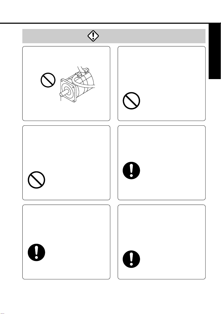
Don't touch the rotating
part of the motor in motion.
Rotating part
Failure to observe this instruction could
result in injuries.
Do not expose the cables to
sharp edges, excessive
pressing forces, heavy
loads or pinching forces.
Failure to observe this
instruction could result in
electric shocks,
malfunction and/or
damages.
Don't subject the product to
water splash, corrosive
gases, flammable gases and
combustible things.
Failure to observe this instruction could result in
fire.
Perform the transportation,
wiring and inspection at
least 10 minutes after the
power off.
Failure to observe this instruction could result in
electric shocks.
Always ask to an electrical engineer for wiring.
Ground the earth terminal
of the amplifier.
Failure to observe this
instruction could result in
electric shocks.
Install an external
emergency stop device so
that you can shut off the
power in any emergency
cases.
Failure to observe this
instruction could result in
injuries, electric shocks, fire,
malfunction and/or mechanical
damages.
-5-
Page 6
Safety Precautions
Caution
(Important)
Use the motor and
amplifier in the specified
combination.
Failure to observe this instruction could result in fire.
If an error occurs,
remove the causes for
the error and secure the
safety before restarting
the operation.
Failure to observe this
instruction could result in
injuries.
Execute the trial operations
with the motor fixed but
without motor load connected.
Connecting a load to the
motor is possible only after
successful trial operation.
Failure to observe this instruction could result in injuries.
Don't touch the motor,
amplifier or its
regenerative discharge
resistor, since they
become hot.
Failure to observe this
instruction could result in
burns.
Avoid extreme
adjustment or change.
Avoid an operation
which causes unstable
action.
Failure to observe this
instruction could result in
injuries.
Don't modify, dismantle
or repair the amplifier.
Failure to observe this instruction could result in fire,
electric shocks and/or injuries.
-6-
Page 7
Caution
Before Use
Don't hold the cables or
motor shaft when
transporting the motor.
Failure to observe this
instruction could result
in injuries.
Don't block the heat
dissipation hole or insert
foreign matters in it.
Failure to observe this
instruction could result
in electric shocks,
injuries and/or fire.
After recovery from the
power failure, the
equipment may restart
suddenly. Don't approach
the equipment
Failure to observe this
instruction could result in
injuries.
*Provide appropriate settings as a preparedness against
the accidental restart of the machine in order to ensure
the safety of personnel.
Observe the voltage
specified.
Failure to observe this
instruction could result in
electric shocks,
injuries and/or fire.
Make sure that the
wirings are made
correctly.
Failure to observe this
instruction could result in
electric shocks, injuries.
This equipment should be
treated as an industrial
waste when it is disposed of.
Do not turn on/off the
main power frequently.
Failure to observe this
instruction could result
in malfunctions.
-7-
Page 8
Introduction
After Opening the Package
• Make sure that the product is what you have ordered.
Check whether the product has been damaged or not during transportation.
•
If the product is not correct, or it has been damaged, contact dealer or sales agent.
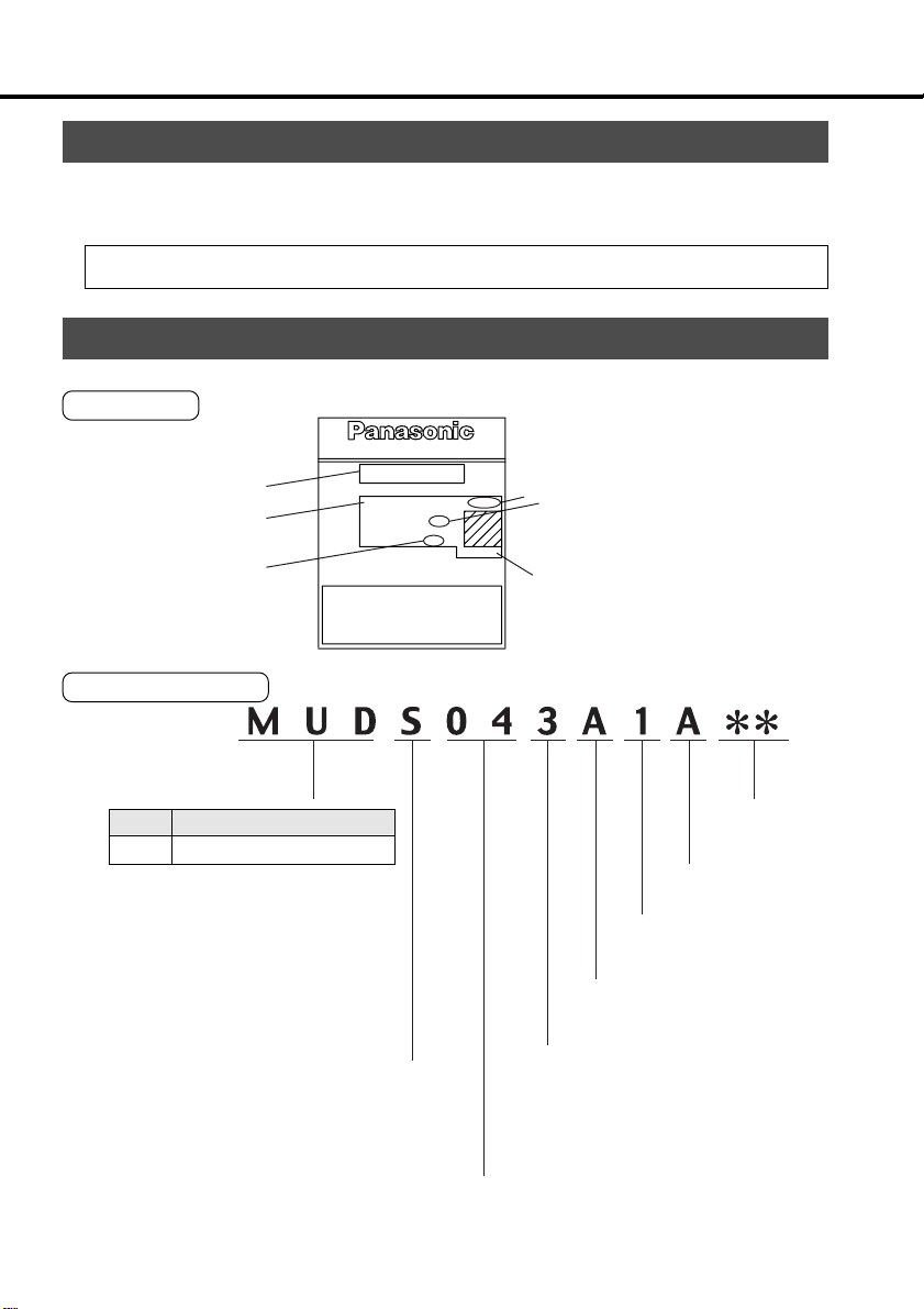
Check the Model of Amplifier
Name plate
Model
Rated input voltage
Rated motor output
Model Designation
Symbol
Applicable motors
MUD
MUMÅi
Extra low inertia
AC SERVO DRIVER
MUDS3A1A1A
Model No.
INPUT OUTPUT ENCODER
Voltage
100-115V 32V
1ø 3ø
Phase
1.0A 1.0A
F.L .C
Freq.
50/60Hz 0~333.3Hz
Power
60/75 Wire Only
Use Copper Conductors Only
Refer to Manual for Wiring and Wire Size
Refer to Manual for Over Load Protection
1~3 5~6
30W
00010001
SER.NO.
478910
Åj
Series symbol
S: S-series
Rated motor output (see
Table 1-a)
Number of pulses of the
encoder(resolution)
2500P/R
Rated output current
Serial Number
Custom specification 1 (1,
2, 3...)
1: Standard
Rotary encoder
(see Table 1-b)
Power supply
1: Single-phase, 100V
2: Single-phase, 200V
3: Three-phase, 200V
5: Three-phase/Single-phase, 200V
(common phase)
11~12
Custom
specification
Custom specification 2
(A, B, C...)
A: Standard
-8-
Page 9
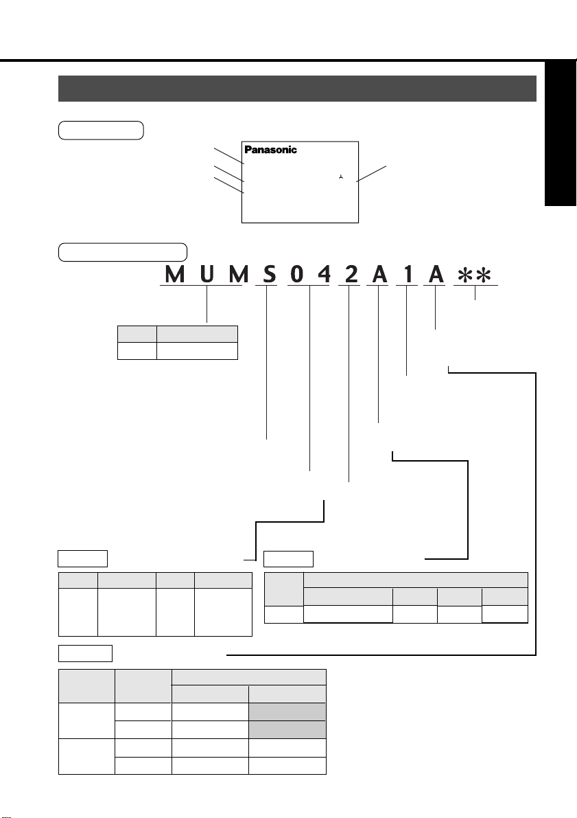
Check the Model of Motor
Name plate
Type
Rated output
Revolution rating
Model Designation
AC SERVO MOTOR
Model No.
MUMS042A1A
INPUT 3ØAC
RATED OUTPUT
200
RATED FREQ.
RATED REV.
3000
92
V
A1.6
kW
0.2
Hz
r/min
CONT. TORQUE
0.64
RATING S1
INS. CLASS B (TÜV) A (UL)
IP65
CONNECTION
SER No.
00010001
MatsushitaElectric Industrial Co..Ltd.
Made in Japan
Before Use
Nm
Serial No
Table 1-a
Symbol
3A
5A
01
Table 1-c
Oil seal
None
Yes
1~3 5~6
Symbol
MUM
Rated Motor Output
Rated output
30W
50W
100W
Motor Structure
Brake
None
Yes
None
Yes
Type
Super low inertia
Symbol
Rated output
02
04
08
Straight
200W
400W
750W
A
B
C
D
478910
11~1 2
Custom specification 2
Motor structure
(see Table 1-c)
Custom specification 1
1: Standard
Rotary encoder
Series symbol
(see Table 1-b)
S: S-series
Rated output
(see Table 1-a)
Voltage
1: 100V
2: 200V
Z: 100/200V
Table 1-b
Symbol
A
Shaft
Key way
Rotary Encoder
Specifications
Type
Incremental
No. of pulses
2500P/r
Resolution
10000
∑ Specifications with the shaft
provided with key way are standard.
E
F
G
H
-9-
Lead wire
11- wire
Page 10

Introduction
Check the Combination of Amplifier and Motor
The amplifier has been designed for use in combination with the specified motors only.
Check the specifications (Series symbol, output rating, voltage rating and encoder type) of
the motor you want to use.
-10-
Page 11
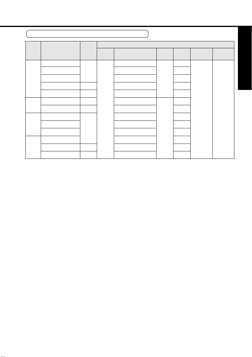
With the incremental type encoder: 2500P/r
Power
supply for
amplifier
MUDS3A1A1A
1-phase,
MUDS5A1A1A
100V
MUDS011A1A
MUDS021A1A
MUDS041A1A
MUDS022A1A
1-phase,
MUDS042A1A
200V
MUDS3A5A1A
3-phase/
1-
MUDS5A5A1A
phase,
MUDS015A1A
200V
MUDS023A1A
3-phase,
MUDS043A1A
200V
MUDS083A1A
Amplifier
Amplifier
Series
type
symbol
Type1
MUMS
Super
Type2
Type3
Type2
Type3
Type1
Type2
Type3
Low
inertia
Motor type
MUMS3AZ
MUMS5AZ
MUMS011A
MUMS021A
MUMS041A
MUMS022A
MUMS042A
MUMS3AZA
MUMS5AZA
MUMS012A
MUMS022A
MUMS042A
MUMS082A
****
****
****
****
****
****
****
****
****
****
****
****
****
Motor
Voltage
100V
200V
Output
rating
30W
50W
100W
200W
400W
200W
400W
30W
50W
100W
200W
400W
750W
Revolution
rating
3000r/min
Encoder
Incremental
2500P/r, 11
wires
Before Use
type
-11-
Page 12
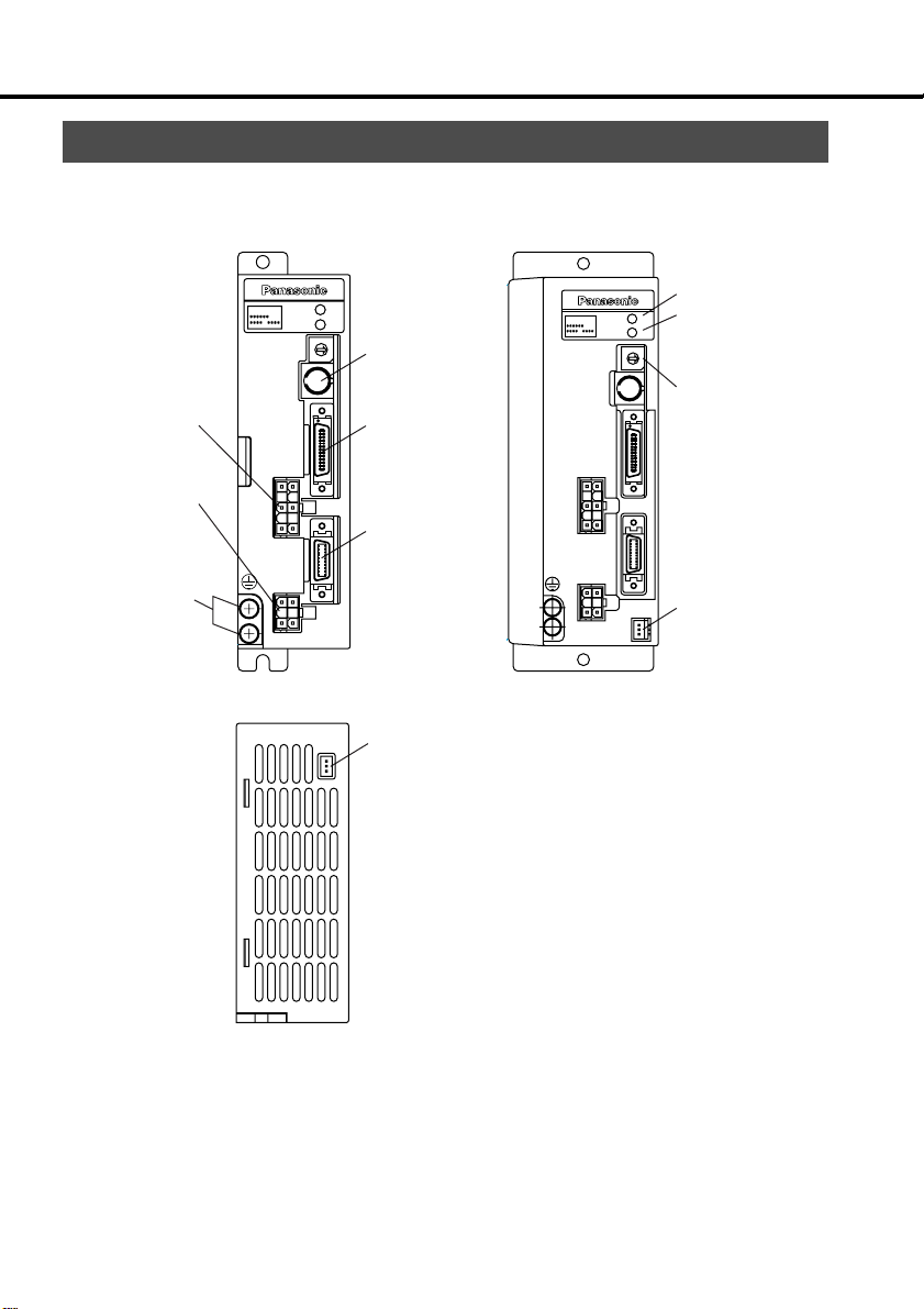
Parts Description
Amplifier
Example: MUDS023A1A
(3-phase, 200V 200W: Type 1)
STATUS
MSDS
ALM CODE
GAIN
CN
SER
Main power
input connector
(L1, L2, L3,P, B)
Motor
connection
(U, V, W, E)
Earth
connections
CN
POWER
CN
MOTOR
CN
I/F
CN
SIG
MON
CN
Communication
connector
CN SER
Controller
connection
(CN I/F)
Encoder
connection
(CN SIG)
Check pins
(CN MON)
Example: MUDS042A1A
(1-phase, 200V 400W: Type 3)
Status LED
CN
MON
Alarm code LED
Rotary switch
for gain (GAIN)
tuning
Check pins
(CN MON)
MSDS
CN
POWER
CN
MOTOR
STATUS
ALM CODE
GAIN
CN
SER
CN
I/F
CN
SIG
<Notes>
For detailed information for each of motor types, see the drawings in the Appendix
(App.50 to 52).
-12-
Page 13
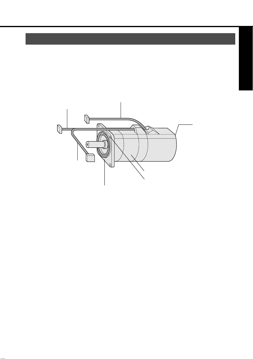
Motor
Example: Super Low-Inertia Motor (MUMS Series, 400W)
Encoder cable
Motor cable
Encoder
Brake cable
(Motor with electromagnetic brake only )
Flange
Frame
Mounting bolt holes (4)
Before Use
<Notes>
For detailed information for each of motor types, see the drawings in the Appendix
(App.48 & 49).
-13-
Page 14
Installation
The amplifier and motor should be properly installed to avoid failures, mechanical damages and injuries.
Amplifier
Location
• Indoors, where the amplifier is not subjected to rain water and direct sun beams. Note
that the amplifier is not a waterproof structure.
• Avoid the place where the amplifier is subjected to corrosive gases, flammable gases,
grinding liquids, oil mists, iron powders and cutting particles.
• Place in a well-ventilated, and humid- and dust-free space.
• Place in a vibration-free space.
Environmental Conditions
Item
Ambient temperature
Ambient humidity
Storage temperature
Storage humidity
Vibration
Not greater than 90%RH (free from condensation)
0 to 55˚C (free from freezing)
-20 to 80˚C (free from condensation)
Not greater than 90%RH (free from condensation)
Not greater than 5.9m/s2 (0.6G) at 10 to 60 Hz
Altitude
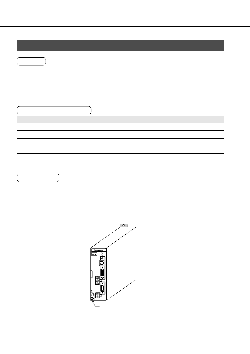
How to Install
•
This is a rack-mount type.
Place the amplifier vertically. Allow enough space surrounding for ventilation.
Front panel mount type (recessed)
Conditions
Not greater than 1000 m
STATUS
MSDS
ALM CODE
GAIN
CN
SER
CN
I/F
CN
POWER
CN
SIG
CN
MOTOR
Earth connection (M4 screw) tightening torque
shall not exceed 0.39 ~ 0.59 N·m.
-14-
Page 15
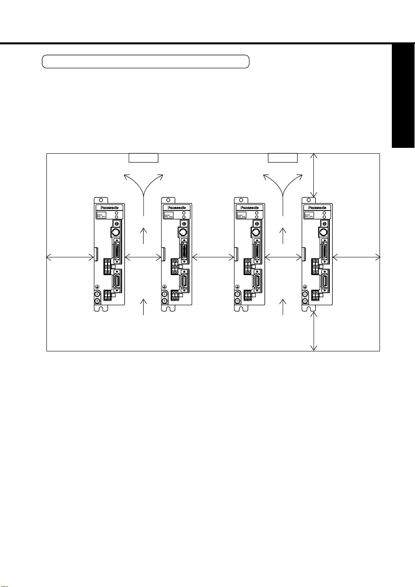
Mounting Direction and Space Requirements
• Allow enough space to ensure enough cooling.
• Install fans to provide a uniform distribution of temperature in the control box.
The airflow of fan is more than 0.43m
amplifier.
• Observe the environmental requirements for the control box, mentioned in the previous
page.
3
/min. And it should be located 10 cm away from the
Before Use
min.
40mm
Fan Fan
min.
100mm
STATUS
MSDS
ALM CODE
GAIN
CN
SER
CN
I/F
CN
POWER
min.
10mm
CN
SIG
CN
MOTOR
STATUS
MSDS
ALM CODE
GAIN
CN
SER
CN
I/F
CN
POWER
min.
10mm
CN
SIG
CN
MOTOR
STATUS
MSDS
ALM CODE
GAIN
CN
SER
CN
I/F
CN
POWER
min.
10mm
CN
SIG
CN
MOTOR
STATUS
MSDS
ALM CODE
GAIN
CN
SER
CN
I/F
CN
POWER
min.
CN
SIG
CN
MOTOR
40mm
min.
100mm
-15-
Page 16

Installation
Motor
Location
•
Indoors, where the amplifier is not subjected to rain water and direct sun beams.
• Avoid the place where the amplifier is subjected to corrosive gases, flammable gases,
grinding liquids, oil mists, iron powders and cutting particles.
• Place in a well-ventilated, and humid- and dust-free space.
• Easy maintenance, inspections and cleaning is also important.
Environmental Conditions
Item
Ambient temperature
Ambient humidity
Storage temperature
Storage humidity
Vibration
Shock
Motor only
With gear
(At rotation)
Motor only
With gear
0 to 40˚C (free from freezing)
Not greater than 85%RH (free from condensation)
-20 to 80˚C (free from freezing)
Not greater than 85%RH (free from condensation)
49 m/s2 (5G) or less at rotation, 24.5 m/s2 (2.5G) or less at rest
High precision and normal type: 24 m/s2 (2G) or less
Standard type: 49 m/s2 (5G) or less
98 m/s2 (10G) or less
High precision and normal type: 98 m/s2 (10G) or less
Standard type: 24 m/s2 (2G) or less
Conditions
How to Install
The motor can be installed either vertically or horizontally. Observe the following notes.
• Horizontal mounting
Place the motor with the cable outlet facing down to prevent the entry of oil and water.
•
• Vertical mounting
• If a motor is coupled with a reduction gear, use a motor equipped with oil seal so that oil
in the reduction gear may not enter into the motor.
Oil and Water Protections
• This motor(IP65 rating) can be used where it is subjected
to water and/or oil drops, but is not water - or oil - proof.
Therefore, the motors should not be placed or used in
such environment.
•
If the motor is coupled with a reduction gear, use the motor
with oil seals to prevent the reduction gear oil from
entering into the motor.
•
Don't use the motor with the cables being immersed in oil
or water.
-16-
Cable
Motor
Oil and water
Page 17
Cable: Stress Relieving
•
Make sure that the cables are not subjected to moments or vertical loads due to external
bending forces or self-weight at the cable outlets or connections.
• In case the motor is movable, secure the cable (proper one supplied together with the
motor) to a stationery part (e.g. floor), and it should be extended with an additional cable
which should be housed in a cable bearer so that bending stresses can be minimized.
• Make the bending radius of cables as large as possible.
(Minimum bend radius: 20 mm)
Permissible Shaft Load
• Make sure that both of radial and thrust load to be applied to the motor shaft during installation and running, are within the specified value of each model.
•
Pay extra attention to installing a rigid coupling (especially an excess bending load which may
cause the damages and/or wear of the shaft and bearings).
• Flexible coupling is recommended in order to keep the radial load smaller than the permissible value, which is designed exclusively for servo motors with high mechanical stiffness.
•
For the permissible shaft load, see "Allowable Shaft Loads Listing" in Appendix.
Installation Notes
•
Don't hit the shaft with a hammer directly while
attaching/detaching the coupling to the motor
shaft.(otherwise the encoder at the opposite
end of the shaft will be damaged).
• Try perfect alignment between shafts (misalignment may cause vibration, and damages of
the bearings).
Before Use
-17-
Motor
Page 18
System Configuration and Wiring
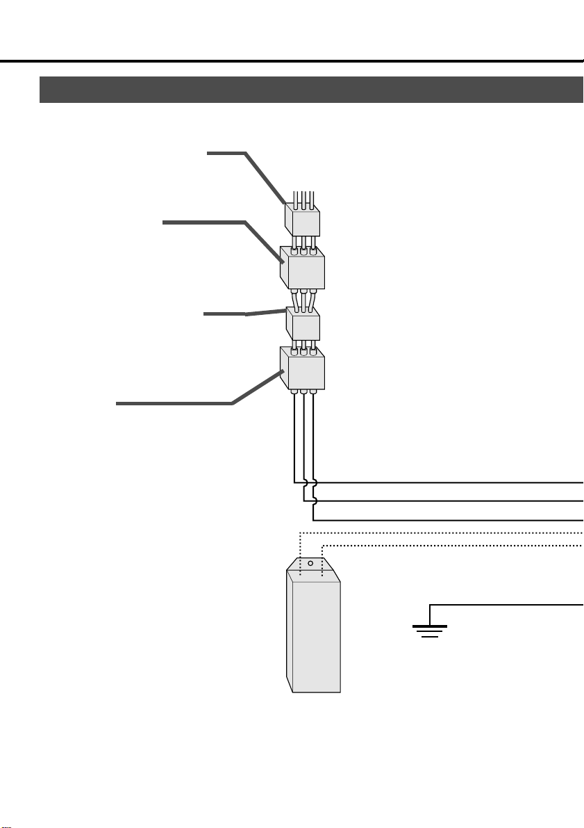
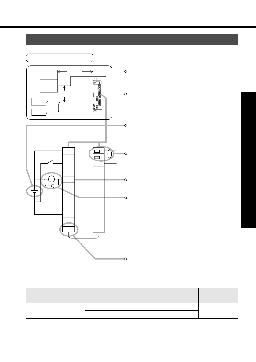
General Wiring Diagram
• Main Circuits
Non-Fuse Breaker (NFB)
Used to protect the power lines:
overcurrent will shut off the circuit.
Noise Filter (NF)
Prevents the external noise from the power
line, and reduces the effect of the noises generated by the servo motor.
Magnetic Contactor (MC)
Turns on/off the main power of the servo
motor.
Used together with a surge absorber.
Reactor (L)
Reduces the harmonic current in the
main power.
Terminals P and B
• In case of use under large regenerative
energy, connect an external
regenerative discharge resistor to P
and B terminals.
<Notes>
Where residual-current-operated
protective device (RCD) is used for
protection in case of direct or indirect
contact. Only RCD of Type B is allowed
on supply side of this Electronic
Equipment (EE).
Ground
Regenerative
discharge resistor
-18-
Page 19
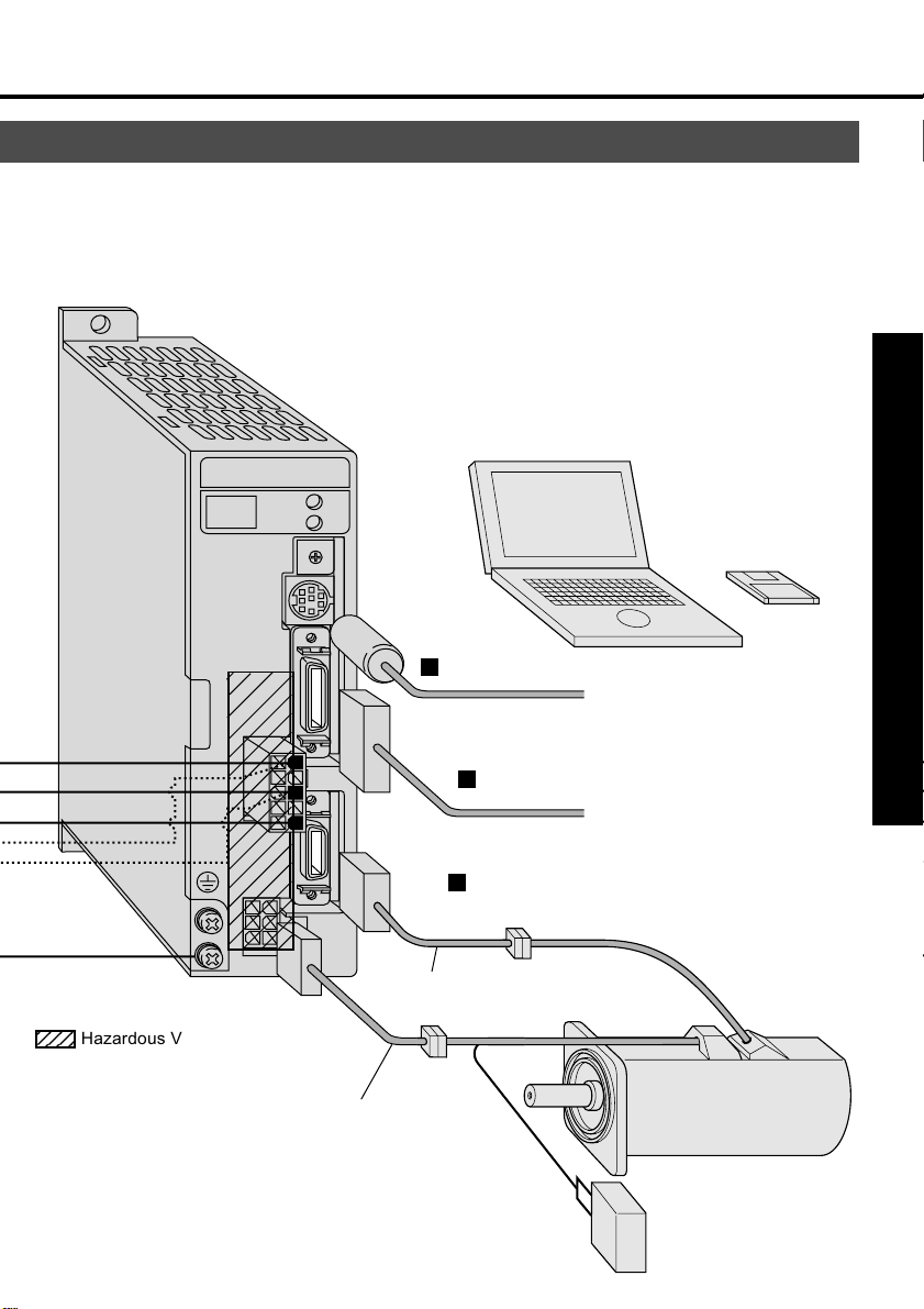
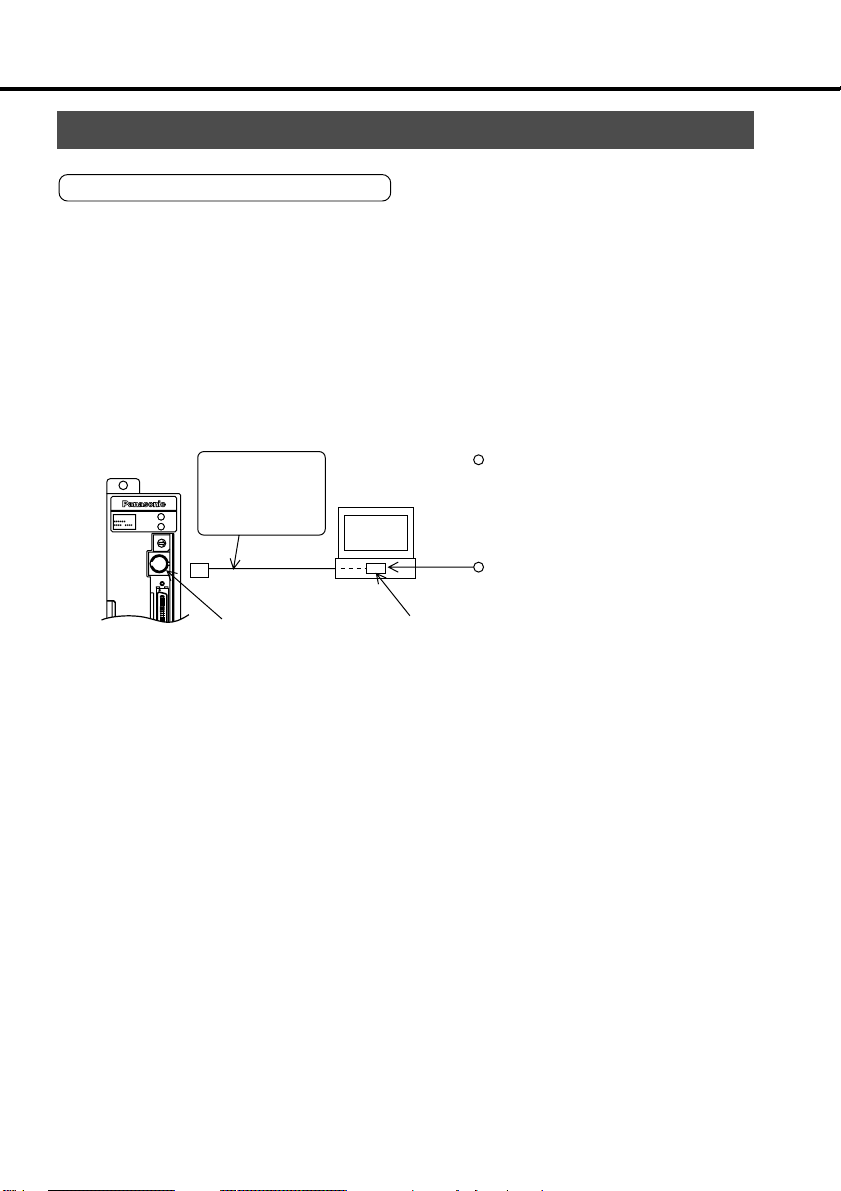
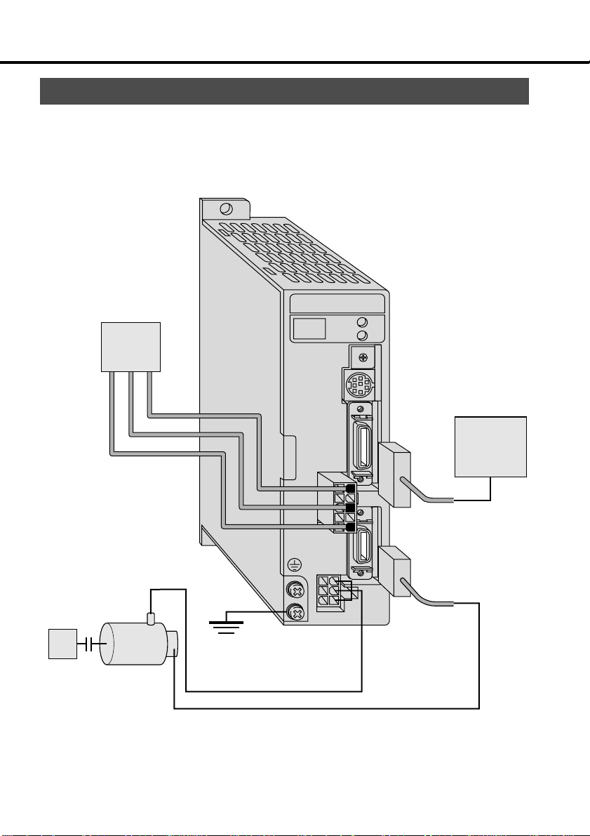
Personal computer
4
Preparations and Adjustments
CN
MOTOR
23
Hazardous Voltage
Others; Low Voltage circuit
CN
POWER
STATUS
ALM CODE
6
GAIN
5
CN
SER
CN
I/F
CN
SIG
Motor cable
Communication
control software
9
8
0
7
1
2
4
3
PANATERM
“
CN SER
(to connect a PC or
controller)
CN I/F
(to connect a controller)
CN SIG
(to connect an encoder)
Encoder cable
Power supply for motor
brake
(24VDC)
-19-
Page 20

System Configuration and Wiring
List of Available Components
Amplifier
Series
MUDS
Output
Voltage
30 ~ 50W
100W
1-phase,
200W
100V
400W
30 ~ 50W
*1-phase,
100W
200V
200W
1-phase,
400W
200V
30 ~ 50W
*3-phase,
100W
200V
200W
400W
3-phase,
750W
200V
Required Power
(at the rated load)
Approx. 0.3kVA
Approx.
0.4kVA
Approx.
0.5kVA
Approx.
1.0kVA
Approx.
0.3kVA
Approx.
0.5kVA
Approx.
0.9kVA
Approx.
0.3kVA
Approx.
0.5kVA
Approx. 0.9kVA
1.3kVA
Approx.
Circuit
breaker
(rated current)
BK251
(5A)
BK2101
(10A)
BK351
(5A)
BK3101
(10A)
BK351
(5A)
BK3101(10A)
BK3151
Noise
filter
DVOP1441
DVOP1442
DVOP1441
DVOP1442
DVOP1441
DVOP1442
Magnetic contactor
(contacts)
BMFT61041N
(3P+1a)
BMFT61541N
(3P+1a)
BMFT61541N
(3P+1a)
MMFT61042N
(3P+1a)
0.75mm
~ 0.85mm
AWG 18
Main circuit wire diameter
(L1 , L2, L3,
U, V, W, E)
2
2
(15A)
As these models with * are used for both 1-phase 200V and 3-phase 200V, make a choice
according to the power source.
•
When these wires are used, wire length between circuit breaker and amplifier should be less than 3 m.
•
The model numbers of circuit breaker and magnetic contactors shown in the above list are manufactured by
Matsushita Electric Works, Ltd.
• Use the circuit breaker as shown in App.3 to meet relevant EC Directives.
•
The model number of noise filters (options) shown in the above are manufactured by Okaya Electric Industries
Co., Ltd.
<Notes>
• CN POWER, CN MOTOR and earth terminals
Wires should be copper conductors of a temperature rating of 60˚C or above.
•
Earth wire diameter should be 2.0 mm2 (AWG14) or larger.
•
Please also consider the electrochemical potentials between metal conductor including closed loop terminals.
The electrochemical potentials shall be less than 0.6V.
- 20 -
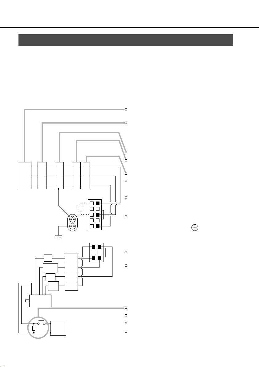
Page 21

For 3-phase 200VAC
3-phase
200V
172167-1
White or yellow
Motor
Red
Black
Green/yellow
1
2
3
4
NFB
172159-1
tyco Electronics AMPtyco Electronics AMP
Noise filter
12~24V
MC
MC
5557-10R-210
5557-06R-210
V
DC
ON
ALM
For 1-phase 100V/200V
Single-phase 100V or
Single-phase 200V
NFB
172167-1 172159-1
tyco Electronics AMP tyco Electronics AMP
Red
1
White or yellow
2
Black
3
Green/yellow
4
Noise filter
ON
MC
MC
5557-10R-210
5557-06R-210
MC
OFF
L
10
L1
8
L2
6
L3
5
3
1
4
6
W
3
9
ALM
13
COM –
OFF
L
10
L1
L2
6
L3
5
3
1
4
6
3
P
N
P
P
N
B
U
V
E
MC
P
N
P
P
N
B
U
V
W
E
Preparations and Adjustments
Motor
9
ALM
ALM
V
DC
12~24V
13
COM –
<Note>
In case that alarm occurs, construct the circuits so that the main power is switched off.
•
- 21 -
Page 22
System Configuration and Wiring
Main Circuits
Always ask to an electric engineer for wiring.
Don't turn on the main power until the wiring and connectings are completed, to avoid electric shocks.
Wiring Instructions
•
Make necessary connections.
For wire diameter, see List of Available Components (page 20).
•
Securely insert connectors.
See the nameplate of the amplifier to check
the power specification.
Install a non-fuse breaker or leakage breaker.
The latter should be a special one intended for
inverters, i.e. with a countermeasure against
higher harmonics.
Install a noise filter without fail.
Install a surge absorber to the magnetic
contactor coil.
Power
supply
NFB
NF MC L
D class ground: 100Ω max.
For wire diameter, see page 20.
U
Red
White or
yellow
Black
Green
yellow
1
V
2
W
3
E
4
CN
POWER
5
P
B
1
10
L1
L2
L3
6
CN
MOTOR
3
14
6
Install an AC reactor.
For three-phase 200V,connect L1(10pin), L2(8pin),
and L3(6pin).
For single-phase 100V and 200V, connect
L1(10pin) and L3(6pin).
Connect to the grounding system of the facility.
Never fail to connect between the amplifier's
protective earth terminal ( ) and control
board's protective earth terminal (ground plate)
in order to avoid electric shocks.
Ensure to connect matching in color between
the motor wires and terminals (U, V, W and E).
Don't short circuit or ground. Don't connect to
the main power.
Motor
Power supply for
DC
elector magnetic brake
24V
(Min, 0.5A)
The electromagnetic brake is not polar-sensitive.
For power capacities, see the App. 7.
For use of the brake, see "Holding Brake" in App. 6.
Install a surge absorber.
- 22 -
Page 23

CN SIG Connector (For Encoder)
Wiring Instructions
The cable length between the amplifier and motor should be max. 20 m. If you use a longer
cable, contact the dealer or sales agent.
Separate these wiring min. 30 cm from the
main circuit wires. Don't lay these wires in
the same duct of the mains or bundle with
them.
Motor
Power
Encoder
min.30cm
max.20m
POWER
MSDS
ALARM
GAIN
RS232C
CN
I/F
CN
POWER
CN
SIG
CN
MOTOR
Preparations and Adjustment
Wiring Diagrams
172171-1
tyco Electronics AMP
Yellow
Orange
Yellow
Green
Blue
Red
Pink
Light
Blue
Purple
White
Black
Moter side
tyco Electronics AMP
5
Z
6
Z
3
B
4
B
1
A
2
A
11
RX
12
RX
13
+5V
14
0V
15
FG
172163-1
Connecting cable
11
12
9
10
7
8
17
18
3
1
4
2
20
CN SIG
Z
Z
B
B
A
A
RX
RX
+5V
0V
+5V
0V
FG
Driver side
When you prepare your own connecting cables see the "Optional Parts"
for connectors, and
1) Follow the wiring diagram and use the
2) Wire material: 0.18 mm
2
(AWG24) or more,
shielded twist-paired wire Å@with an
enough bending durability,
3) Signal/power paired wires should be of a
twist-paired type.
4) Shield:
• The shield at the amplifier side should be
connected to Pin 20 (FG) of CN SIG Connector.
• The shield at the motor side should be connected to: connector of 15 pins type
5) If the cable is longer than 10 m, the encoder power line (+5V and 0V) should be
dual per the figure shown left.
6) Other terminals should be left
unconnected.
- 23 -
Page 24
System Configuration and Wiring
MSDS
CN
I/F
ALM CODE
STATUS
GAIN
CN
SER
CN SER Connector
For RC232C communications
Connect a personal computer to the amplifier with RS232C at 1:1, and use the
communication control software "PANATERM“" (Option). Operate "PANATERM“"
on the personal computer. Convenient functions of high operability can be
obtained such as monitor and parameter setting and setting change and
waveform graphic display.
Connection
Exclusive
connection cable
(Option)
Personal
computer
See App. 44.
CN SER RS232C connector
Insert and pull out connector
after cutting power to both
personal computer and
amplifier
Securely tighten the fixing
screw
- 24 -
Page 25
List of Available Components
CN I/F Connector (For Controller)
Wiring Instructions
Controller
Power
supply
Motor
max. 3 m
min. 30 cm
POWER
MSDS
ALARM
GAIN
RS232C
CN
I/F
CN
POWER
CN
SIG
CN
MOTOR
Place the peripheral devices such as the
controller max. 3 m away from the amplifier.
Separate these wiring min. 30 cm from the main
circuit wires. Don't lay these wires in the same
duct of the mains or bundle with them.
T
he control power (VDC) between COM+ and COM- should
Preparations and Adjustments
be supplied by the customer (recommended voltage:
+12VDC to +24VDC).
COM+
GND
1
2
Use a shielded twist-paired type for the wiring
of pulse input, encoder signal output, etc.
Do not apply power higher than 24V or 50mA to control
DC
V
signal output terminal.
If you directly activate a relay using the control
signal,install a diode in parallel to the relay as
COM-
shown in the left figure. Without a diode or with
it but placed in the opposite direction, the
amplifier will be damaged.
FG
CN I/F
• CN I/F Connector Specifications
Receptacle on the
amplifier side
10226-52A2JL
Part description
Solder type plug (Soldering type)
Connector cover
• The CN I/F pins assignment is shown in "Optional Parts" in Appendix.
The Frame Ground (FG) is connected to
an earth terminal in the amplifier.
Connector to controller side
Part No.
10126-3000VE
10326-52A0-008
- 25 -
Manufacturer
Sumitomo
three M
Page 26
System configutration and wiring
1
4.7k
Ω
220
Ω
220
Ω
COM+
PULS2
SIGN1
SIGN2
GND
OA+
OA
OB+
OB
OZ+
OZ
CZ
SPM
IM
22
23
24
25
14
15
16
17
20
330Ω
330Ω
330Ω
1
2
3
21
18
19
1K
1K
PULS1
SRV-ON
A-CLR
CL
GAIN
DIV
CWL
CCWL
ALM
COIN
BRKOFF
COM-
WARN
CN I/F
FG
2
3
4
5
6
7
8
9
10
11
13
12
26
V
DC
12~24V
CN MON
GND
Monitor pin
Monitor pin
If this is an open collector I/F,
see P1 in page 33.
Velocity monitor
output
Torque monitor
output
Command
pulse input
A-phase
output
B-phase
output
Z-phase
output
Z-phase output (open collector)
2nd gain switching
Servo-ON
Alarm clear
Position error counter clear
Command pulse scaler switch
CW overtravel inhibit
CCW overtravel inhibit
Servo alarm
In-position
Mechanical brake release
Alarm
(Pr09)
Scaler
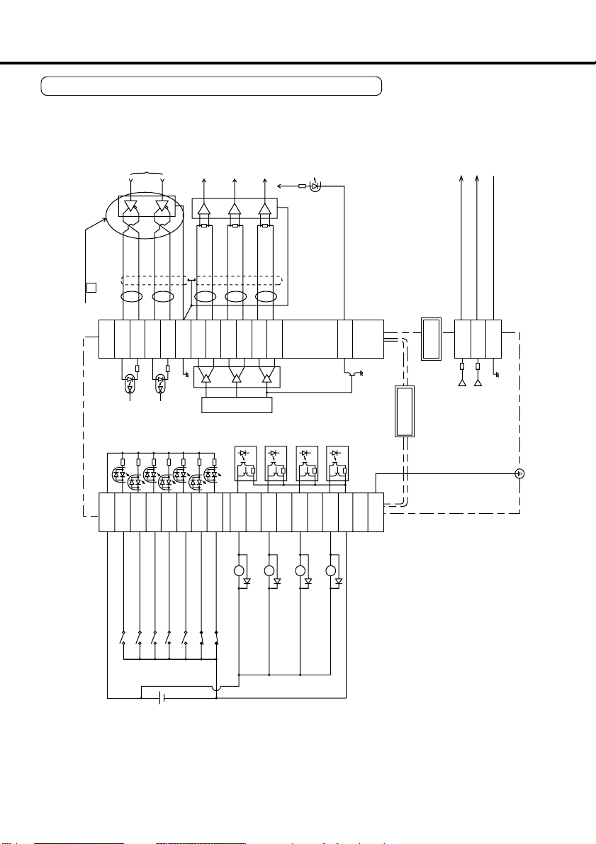
Circuits Available for Typical Control Modes
• CN I/F Wiring for Position Control
- 26 -
Page 27

1
4.7k
Ω
COM+
PULS2
SIGN1
SIGN2
OA+
OA
OB+
OB
OZ+
OZ
CZ
SPM
IM
22
23
24
25
15
GND
14
16
17
20
21
1
2
3
18
19
1K
1K
PULS1
SRV-ON
A-CLR
INTSPD2
ZEROSPD
INTSPD1
CWL
CCWL
ALM
COIN
BRKOFF
WARN
COM
-
CN I/F
FG
3
4
2
5
6
7
8
9
10
11
12
13
26
V
DC
12~24V
220
Ω
220
Ω
CN MON
GND
330Ω
330Ω
330Ω
Servo-ON
Alarm clear
CCW overtravel inhibit
A-phase
output
B-phase
output
Z-phase
output
CW overtravel inhibit
Servo alarm
At-speed
Mechanical brake release
Alarm
(Pr09)
Internal vel .cmnd.select 1
Internal vel .cmnd.select 2
Speed zero clamp
Scaler
Z-phase output (open collector)
Monitor pin
Monitor pin
Velocity monitor
output
Torque monitor
output
Preparations and Adjustments
• CN I/F Wiring for Internal Velocity Control
- 27 -
Page 28

System configuration and wiring
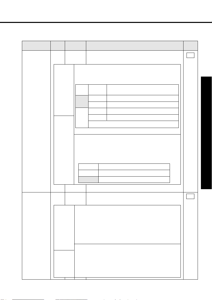
CN I/F Connector
Input Signals (Common) and their Functions
Signal
Control signal
power
(+)
Control signal
power
(-)
Servo-ON
Alarm
clear
Position error
counter
clear/Internal
command
velocity
selection 2
Pin
Symbol Function
No.
COMÅ{
1
13
COMÅ|
2
SRV-ON
<Notes>
1. This signal becomes effective about two seconds after power on
(see the Timing chart).
2. Don't use this Servo-ON or Servo-OFF signal to turn on or off the
motor. (See App.8)
•
Allow at least 100ms delay after the amplifier is enabled before any
command input is entered.
•
By opening the connection to COM- , the amplifier will be disabled(Servo-OFF) and
the current flow to the motor will be inhibited.
•
Operation of the dynamic brake and clearing action of the position error counter can be
selected using Pr69 (Sequence under Servo-OFF).
3
A-CLR
4
CL/
INTSPD2
Position
control
Internal
velocity
control
•
Connect to (+) of an external power supply(12VDC to 24VDC).
•
Use power supply of 12V±10%Å`24V±10%
•
Connect to (-) of an external power supply(12VDC to 24VDC).
•
The required capacity depends on the I/O circuit configuration.
0.5A or larger is recommended.
•
When this signal is connected to COM-, the dynamic brake will be
released and the amplifier is enabled. (Servo-ON).
•
If the COM- connection is kept closed for more than 120 ms,
the alarm status will be cleared.
•
Some alarms cannot be cleared by this input.
For details, see Protective Functions on page 60.
The function differs depending on the control mode.
• Clears the position error counter. Connect to COMto clear the counter.
•
Use Pr4D to select the clear mode (0 Default: level 1: Edge)
•
The internal velocity selection 2 (input) is valid. 4 kinds of
velocity settings are available by combination with DIV/
INTSPD1 input. See control mode setting Pr02 (APP. 16).
I/F
circuit
Å\Å\
SI
page 33
SI
page 33
SI
page 33
- 28 -
Page 29
Signal
Gain
switching/
Speed zero
clamp
Pin
Symbol Function
No.
GAIN/
5
ZEROSPD
Position
control
Internal
velocity
control
The function differs depending on the control mode.
•
The functions depend on the value of Pr30.
•
Gain switching input results. Input for switching PI/P
operation and No. 1/No. 2 gains.
Connection
Pr30
to COM-
value
0
Open
(Default)
Close
1
Open
Close
At Pr31 value of 2
•
For No.2 Gain change Funcution, see Protective Adjustments on page 57.
•
Speed zero clamp input results. With COM- open, the
velocity command is considered zero.
• This input can be made disabled using Pr06.
• Default: Contact is set. With COM- open, the velocity
command is considered zero.
Pr06 value
0
1
[Default]
Speed loop:PI(ProportionalÅEIntegration) operation
Speed loop: P (Proportion) operation
#1 gain selection (Pr10, 11, 12, 13, 14)
#2 gain selection (Pr 18, 19, 1A, 1B, 1C)
ZEROSPD is disabled.
ZEROSPD is enabled
Function
Meaning
I/F
circuit
SI
page 33
Preparations and Adjustments
Command
pulse scaler
switch/
Internal
command
velocity
selection 1
6
INTSPD1
Position
control
Internal
velocity
control
DIV/
The function differs depending on the control mode.
This is the input to switch command pulse scaler.
•
•
With COM- closed, the numerator of the command scaler is changed
from the value stored in Pr46 (Numerator of 1st Command Scaler) to
the value stored in Pr47 (Numerator of 2nd Command Scaler).
<Note>
Don't enter command pulses 10 ms after or before switching.
•
The internal velocity selection 1 (input) is valid. 4 kinds of velocity
settings are available by the combination with CL/INTSPD2 input.
• See control mode setting Pr02 (APP. 16).
- 29 -
SI
page 33
Page 30

System configuration and wiring
Signal
CW overtravel
inhibit
CCW overtravel
inhibit
Pin
Symbol Function
No.
7
CWL
8
CCWL
•
If COM- is opened when the movable part of the
machine has moved to CW exceeding the limit, the
motor does not generate torque.
•
If the COM- is opened when the movable part of the
machine has moved CCW exceeding the limit, the
motor does not generate torque.
•
When Pr04 (Overtravel Limit Input Disabled) = 1, CWL
and CCWL inputs are disabled. The default is
"Disabled" (1).
•
The dynamic brake can be made operable during CWL/
CCWL inputs valid. Use Pr66 (Dynamic Brake
Inactivation at Overtravel Limit) to make the dynamic
brake operable. The default is to allow the dynamic
brake to operate. (Pr66 value is 0.)
Input Signals (Position Control) and their Functions
Signal
Command
pulse
Command
sign
Pin
Symbol Function
No.
22
23
24
25
PULS1
PULS2
SIGN1
SIGN2
This is the input terminal for command pulses. The maximum allowable
•
input frequency is 500 kpps for line amplifier input and 200 kpps for
open collector input. The amplifier is the high-speed photocoupler
of TOSHIBA TLP554 or equivalent.
• The input impedance of PULSE and SIGN signals is 220Ω.
•
Command pulses can be input in three different ways. Use Pr42 to
select one of the following. (See App.26.)
1) Quadrature (A and B) input
2) CW (PULSE)/CCW (SIGN) pulse input
Command pulse (PULS)/Sign (SIGN) input
3)
I/F
circuit
SI
page 33
SI
page 33
I/F
circuit
PI
page 33
- 30 -
Page 31

Output Signals (Common) and their Functions
Signal
Servo alarm
In-position/
At-speed
Mechanical
brake release
Warning
Pin
Symbol Function
No.
9
ALM
10
COIN
Position
control
Internal
velocity
control
11
BRK-OFF
12
WARN
Pr0A value
0
1
2
[Default]
3
4
5
• This output (transistor) turns off, when the
detector detects an alarm.
• The function differs depending on the control
mode.
• In-position output
•
Output(transistor) turns ON when the position error is below the
preset value by Pr60 (In-Position Range).
• At-speed.
•
This output (transistor) turns ON, when the motor speed exceeds
the preset value by Pr62 (At-Speed).
•
Used to release the motor electromagnetic brake.
•
Use "Output (transistor) ON" to release the electromagnetic brake.
• See Timing Charts (App. 10 -13).
•
Signal which is selected at Pr09 (warning output selection)
will be turned on. This output (transistor) turns ON at least
for one second after warning indication signals are output.
"In-torque limiting" output
Output(transistor) turns ON during the In-toque limiting.
Zero speed output
Output(transistor) turns ON when the motor speed becomes
lower than that of the preset speed with Pr61(Zero speed).
Output of both over-regeneration and overload warnings
Output(transistor) turns ON when either one of overregeneration or overload is activated.
Over-regeneration warning output
Output(transistor) turns ON when the over-regeneration
(more than 85% of permissible power of the internal
regenerative discharge resistor) warning is activated.
Overload warning output
Output(transistor) turns ON when the overload (the
effective torque is more than 85% of the overload trip
level) warning is activated.
Does not function, although displayed.
I/F
circuit
SO1
page 34
SO1
page 34
Preparations and Adjustments
SO1
page 34
SO1
page 34
Function
- 31 -
Page 32

System configuration and wiring
Signal
A-phase output
B-phase output
Z-phase output
Z-phase output
Signal
ground
Pin
Symbol Function
No.
•
15
16
17
18
19
20
21
14
OA +
OA OB +
OB OZ +
OZ -
CZ
GND
Provides differential outputs of the encoder signals
(A, B and Z phases) that come from the divider
(equivalent to RS422 signals).
•
The logical relation between A and B phases can be selected by
Pr45 (Output Pulse Logic Inversion).
• Not insulated
• Z-phase signal output in an open collector
• Not insulated
• Signal ground for pulse output
Internally isolated from the control power (COM-).
•
Others
Signal
Frame
ground
Pin
Symbol Function
No.
• Internally connected to the earth terminal.2 6 FG ------
Output Signals (Others) and their Functions
Signal
Speed
monitor
signal
output
Torque
monitor
output
Signal
ground
Pin
Symbol Function
No.
1
2
3
SP
IM
GND
Outputs the motor speed, or voltage in proportion to the
•
commanded speed with polarity.
+ : CCW rotation
– : CW rotation
Use Pr07 (Velocity Monitor Selection) to switch between actual
•
and commanded speed, and to define the relation between
speed and output voltage.
•
Outputs the output torque, or voltage in proportion to the position
error with polarity.
+ : generating CCW-torque
– : Fgenerating CW-torque
Use Pr08 (Torque Monitor Selection) to switch between torque
•
and positional error, and to define the relation
between torque/positional error and output voltage.
• Signal ground for monitor signal
• Internally isolated from the control power (COM-
).
I/F
circuit
PO1
page 34
PO2
page 35
------
I/F
circuit
I/F
circuit
AO
page 35
AO
page 35
-----
- 32 -
Page 33

CN I/F Connector
Interface Circuit (Input Circuit)
Connecting to
SI
sequence input signals
•
Connect to a contact of switch and relay, or a tran-
sistor of an open collector output.
•
Use a switch or relay for micro current so that in-
sufficient contact can be avoided.
•
Can be used with COM- instead of COM+
PI Command pulse
input circuit
1) Line Amplifier I/F
•
This is a good signal transmission method that is
less sensitive to noises. We recommend you to
use this to maintain the reliability of signals.
2) Open Collector I/F
This uses an external control power supply(VDC).
•
•
This requires a current-limiting resistor correspond-
ing to the capacity of the VDC value.
VDC R value
12V 1kΩ1/4W
24V 2kΩ1/4W
V
DC
V
DC
Available at reverse polarity
1)
2)
12~24V
12~24V
AM26LS31or equivalent
Relay
Relay
R
R
1
V
DC
COM+ 4.7k
Servo-ON or
other input
Servo-ON or
other input
COM+ 4.7k
1
PULS1
22
23
PULS2
SIGN1
24
25
SIGN2
14
GND
22
23
24
25
14
220Ω
220Ω
PULS1
PULS2
SIGN1
SIGN2
GND
Ω
Preparations and Adjustments
Ω
220Ω
220Ω
V
DC - 1.5
R + 220
10mA
shows a pair of twisted wires.
- 33 -
Page 34

System configuration and wiring
Interface Circuit (Output Circuit)
SO1
Sequence output circuit
•
This comprises a Darlington amplifier with
an open collector. This is connected to a
relay or photo coupler.
• There exists a collector-to-emitter
voltage V
transistor ON, because of Darlington
connection of the output transistor.
Note that normal TTL IC can't be
directly connected since this
does not meet V
•
If the recommended current value of the actual
photocoupler is 10mA, calculate the resistance
using the formula below.
For the recommended current value, see the data sheets
of actual equipment and photocoupler.
CE(SAT) of approx. 1.2V at
IL requirement.
DC - 2.5
V
R =
10
[KΩ]
12~24V
Install as per the fig. shows
without fail
SO1
ALM
V
DC
R [kΩ]
SO1
WARN
or other
signal
COM–13
Maximum rating:
30V, 50mA
PO1
Line Driver (Differential Output)
Output
• Provides differential outputs of encoder
signals (A, B and Z phases) that come
from the scaler.
• Receive these signals with a line receivers. In this case, install a resistor of
approx. 330Ω between the inputs.
shows a pair of twisted
wires.
AM26LS32
or equivalent
OA+
OA-
OB+
OB-
OZ+
OZ-
Connect the amplifier signal grounds to the
controller.
- 34 -
AM26LS31
or equivalent
15
16
17
18
19
20
GND
14
A
B
Z
Page 35

PO2
Open Collector Output
• Outputs Z-phase signals among those
from the encoder. The outputs are noninsulated.
• Receive these signal with high-speed
photo coupler at controller side, since
these Z-phase signal width is normally
narrow.
shows a pair of twisted wires.
CN MON Connector
Monitor Circuit (Output Circuit)
AO
Analogue Monitor Output
• Output from CN MON Connector
• This output is the velocity monitor signal
(SP) or torque monitor signal (IM).
The signal range is approx. 0 to 9V.
•
• The output impedance is 1kΩ. Pay attention to the input impedance of your measuring instruments and
external circuits connected.
Maximum rating:
1914CZ
GND
High-speed
photo coupler
TOSHIBA TLP554 or equivalent
CN MON
1k
SP1
Measuring
instrument
or external
circuit
1k
2
IM
GND
3
30V, 50mA
Preparations and Adjustments
Ω
Ω
<Resolution>
1) Velocity monitor signal (SP): 8r/min./
LSB calculated from 6V/3000r/min
(Pr07 = 3)
2) Torque monitor signal (IM): 0.4%/LSB
calculated from 3V/rated value (100%)
- 35 -
Page 36

Parameter Setting
Overview
The servo amplifier has various parameters that are used for adjusting or setting the features or functions of the amplifier. This section describes the purpose and functions of these parameters. Understanding these parameters is
essential for obtaining the best, application-specific operation of the amplifier.
You can view, set and adjust these parameters using your personal computer
with the communication software PANATERM“.
Parameter Groups and Listing
Group
Function selection
Adjustment
Position control
Internal velocity and
torque control
Sequence
For details, see "Details of Parameters" in Appendix.
ParameterNo.
Pr**
00 ~ 0F
10 ~ 1F
20 ~ 22
30 ~ 35
40 ~ 4D
53 ~ 5A
5E
60 ~ 6C
You can select the control mode, allocate I/O signals,
and set the baud rate and etc.
You can set various factors and constants such as
the servo gains (1st and 2nd) for position, velocity
and integration, and time constants of filters.
Real time auto-tuning parameters. You can set the
real time auto-tuning mode, select the machine
stiffness, etc.
You can set the parameters relating to the switching between 1st and 2nd gains.
You can set the input format of command pulses,
logical selection, encoder pulse rate and pulse scaler.
You can set the internal speed (1st to 4th), and it's
acceleration and deceleration time.
You can set the torque limit.
You can set the conditions for detecting the output such as inposition and zero-speed, and set the processing conditions at
excess position error, etc.
You can also set the conditions for stopping at the main poweroff, in-alarm and servo-off, or conditions for the error counter
clearance, etc.
Brief explanation
<Notes>
Parameters marked with * are enabled, when set data are written to EEPROM,
main power is once turned OFF and then turned ON again.
- 36 -
Page 37

Parameters for Selecting Function
Parameter
NO.
(
Pr**
)
Åñ0 0
Åñ0 1
Åñ0 2
Åñ0 3
Åñ0 4
Åñ0 5
Åñ0 6
Åñ0 7
Åñ0 8
Åñ0 9
Åñ0 A
Åñ0 B
Åñ0 C
Åñ0 D
0 E, 0 F
For values marked with *, see page 36.
Axis address
(Internal use)
Control mode set-up
(Internal use)
Overtravel Input inhibit
(Internal use)
ZEROSPD input selection
Speed monitor(SP) selection
Torque monitor (IM) selection
Warning output selection
(Internal use)
(Internal use)
Baud rate set-up of RS232C
(Internal use)
(Internal use)
Parameter description
Range Default Unit
0 ~ 15
-----
0 ~ 1
------
0 ~ 1
----0 ~ 1
0 ~ 9
0 ~ 5
0 ~ 5
------
------
0 ~ 2
------
------
1
0
0
1
1
1
1
3
0
2
1
1
2
2
0
Parameters for Adjusting Time Constants of Gain Filters, etc.
Parameter
NO.
(
Pr**
)
Åñ1 0
Åñ1 1
Åñ1 2
Åñ1 3
Åñ1 4
Åñ1 5
Åñ1 6
Åñ1 7
Åñ1 8
Åñ1 9
Åñ1 A
Åñ1 B
Åñ1 C
Åñ1 D
Åñ1 E
Åñ1 F
1st position loop gain
1st velocity loop gain
1st velocity loop integration time constant
1st speed detection filter
1st torque filter time constant
Velocity feed forward
Feed forward filter time constant
(Internal use)
2nd position loop gain
2nd velocity loop gain
2nd velocity loop integration time constant
2nd speed detection filter
2nd torque filter time constant
Notch frequency
Notch width selection
Disturbance torque obserber
Parameter description Range Default Unit
0
~
1
1
0
0
0
0
1
1
0
100
~
~
0
~
~
~
~
----- ~
~
~
0
~
~
~
0
~
0 ~ 8
2000
3500
1000
5
2500
100
6400
2000
3500
1000
5
2500
1500
4
100
100
50
4
50
0
0
0
100
100
50
4
50
1500
2
8
------
------
------
------
------
------
-----
------
------
------
------
------
------
------
------
1/s
Hz
ms
------
0.01ms
%
0.01ms
-----1/s
Hz
ms
------
0.01ms
Hz
------
------
Preparations and Adjustments
- 37 -
Page 38

Parameter Setting
Parameters for Defining the Real Time Auto Gain Tuning
Parameter No.
(Pr**)
Åñ2 0
Åñ2 1
Åñ2 2
Åñ2 3
2 4 ~ 2 F
Inertia ratio
Real time auto tuning set-up
Machine stiffness at auto tuning
(Not available)
(Internal use)
Parameter description Range Default Unit
0 ~ 10000
Parameters for Adjustments (for 2nd Gain)
Parameter No.
(Pr**)
Åñ3 0
Åñ3 1
Åñ3 2
Åñ3 3
Åñ3 4
Åñ3 5
Åñ3 6
3 7 ~ 3 9
3 E ~ 3 F
2nd gain action set-up
Position control switching mode
Position control switching delay time
Position control switching level
Position control swiching hysteresis
Position loop gain switching time
(Not available)
(Not available)
(Internal use)
Parameter description Range Default Unit
0 ~ 10000
0 ~ 10000
0 ~ 10000
0 ~ 10000
0 ~ 3
0 ~ 9
-----
-----
0 ~ 1
0 ~ 8
-----
-----
-----
100
0
2
100
0
0
0
0
0
0
0
0
0
0
%
-----
-----
-----
-----
-----
-----
166µs
-----
-----
(1 + Setting value)
x166µs
-----
-----
-----
- 38 -
Page 39

Parameters for Position Control
Parameter No.
(Pr**)
*4 0
*4 1
*4 2
4 3
*4 4
*4 5
Åñ4 6
Åñ4 7
Åñ4 8
Åñ4 9
Åñ4 A
Åñ4 B
Åñ4 C
Åñ4 D
4 E, 4 F
For values marked with *, see <Note> in page 36.
Command pulse multiplier set-up
Command pulse logic inversion
Command pulse input mode set-up
(Internal use)
Output pulses per single turn
Pulse output logic Inversion
Numerator of 1st command pulse ratio
Numerator of 2nd command pulse ratio
(Internal use)
(Internal use)
Multiplier of numerator of command pulse ratio
Denominator of command pulse ratio
Smoothing filter set-up
Counter clear input
(Internal use)
Parameter description Range Default Unit
1 ~ 16384
1 ~ 10000
1 ~ 10000
0 ~ 17
1 ~ 10000
Parameters for Velocity and Torque Control
Parameter No.
(Pr**)
Åñ5 0
Åñ5 1
Åñ5 2
Åñ5 3
Åñ5 4
Åñ5 5
Åñ5 6
Åñ5 7
Åñ5 8
Åñ5 9
Åñ5 A
Åñ5 B
Åñ5 C
Åñ5 D
Åñ5 E
Åñ5 F
(Internal use)
(Internal use)
(Internal use)
1st internal speed
2nd internal speed
3rd internal speed
4th internal speed
(Internal use)
Acceleration time set-up
Deceleration time set-up
S-shaped Accel./Decel. time set-up
(Internal use)
(Internal use)
(Internal use)
Torque limit set-up
(Internal use)
Parameter description Range Default Unit
- 10000 ~ 10000
- 10000 ~ 10000
- 10000 ~ 10000
- 10000 ~ 0000
0 ~ 5000
0 ~ 5000
0 ~ 500
0 ~ 500
1 ~ 4
0 ~ 3
0 ~ 3
1
0 ~ 1
-----
-----
0 ~ 7
0 ~ 1
-----
-----
-----
-----
-----
-----
-----
-----
-----
4
0
1
1
2500
0
10000
10000
10000
10000
0
10000
1
0
0
500
1
0
0
0
0
0
300
0
0
0
0
30
0
300
0
-----
-----
-----
-----
-----
-----
-----
-----
-----
-----
n
2
-----
-----
-----
-----
-----
----r/min
r/min
r/min
r/min
-----
2ms/kr/min
2ms/kr/min
2ms
-----
-----
-----
%
-----
Preparations and Adjustments
- 39 -
Page 40

Setting the Parameters
Parameters for Sequence
Parameter No
(Pr )
Åñ6 0
Åñ6 1
Åñ6 2
Åñ6 3
Åñ6 4
Åñ6 5
Åñ6 6
Åñ6 7
Åñ6 8
Åñ6 9
Åñ6 A
Åñ6 B
* 6 C
6 D ~ F
For values marked with *, see <Note> in page 36.
Parameter description Range Default Unit
In-position range
Zero speed
At-speed
Position error set-up
0 ~ 32767
0 ~ 10000
0 ~ 10000
0 ~ 32767
Position error invalidation
(Internal use)
Dynamic Brake inhibition at overtravel limit
(Internal use)
Sequence at alarm
Sequence at Servo-OFF
Mech. break action set-up at motor stadstill
Mech. break action set-up at motor in motion
External regenerative discharge resistor selection
(Internal use)
0 ~ 1
------
0 ~ 1
-----0 ~ 3
0 ~ 7
0 ~ 100
0 ~ 100
0 ~ 2
------
10
50
1000
1875
0
1
0
0
0
0
0
0
2
0
Pulse
r/min
r/min
256Pulse
------
------
------
------
------
-----2ms
2ms
------
------
Set-up range of excessive positional deviation of Pr63 is "Set-up value x 256 pulses".
Set-up is made before shipment so that the excessive positional deviation error takes
place at value in excess of 1875 x 256 pulses.
Pr5E Torque limit set-up
Power supply
for amplifier
Single-phase
100V
Single-phase
200V
3-phase /
Single-phase
200V
3-phase
200V
Amplifier
MUDS3A1A1A
MUDS5A1A1A
MUDS011A1A
MUDS021A1A
MUDS041A1A
MUDS022A1A
MUDS042A1A
MUDS3A5A1A
MUDS5A5A1A
MUDS015A1A
MUDS023A1A
MUDS043A1A
MUDS083A1A
Amplifier
type
Type 1
Type 2
Type 3
Type 2
Type 3
Type 1
Type 2
Type 3
Default
300
330
350
330
300
330
300
• Pr5E "Torque limit set-up"
disables set-up in excess of
the values set up for the
system parameter "Max. torque
set-up".
Values for "Max. torque set-up"
are same as defaults.
• The system parameters are
fault parameters that cannot
be changed with PANATERM
or on the operation panel.
“
- 40 -
Page 41

Setting the Parameters
• You can set the Parameters with
your personal computer with the S-series communication software PANATERM“.
<Notes>
For the use of PANATERM“ for parameter handling, see the instruction manual of the software.
Preparations and Adjustments
Overview of PANATERM
“
You can conduct the following operations using PANATERM“:
1)
Setting the Parameters for amplifier, storing them, and writing in the memory (EEPROM)
2)
Monitoring input/output status, monitoring pulse input, monitoring load ratio.
3)
Checking current error status and error history
4)
Measurement of wave form graphic data, and storage and reading of the data
5)
Automatic tuning
6)
Measurement of frequency characteristics
How to Connect
POWER
MSDS
ALARM
GAIN
CN
SER
CN
I/F
CN
POWER
CN
SIG
CN
MOTOR
RS232C cable
Connect to
CN SER.
DVOP1960
DVOP1160
Setup disc of DVOP2820
communication software
PANATERM
(DOS/V)
(For PC-98 series)
“
- 41 -
Page 42

Setting the Parameters
Installing PANATERM“ on a hard disc
<Notes>
1. The memory capacity of the hard disc should be 15MB or more. Prepare OS of Windows
or Windows
2. Install PANATERM
98.
“
with setup discs, otherwise the software does not work.
“
Procedure
1)
Turn on your personal computer. Start Windows“95 (or 98).
(If there is any application program on, close all of them.)
2) Insert the PANATERM
3) Start Explorer, and switch (select) to the floppy disk drive. (For the procedure for starting the Explorer program,
see the instructions for Windows
4) Double click on the setup program (Setup. exe) in the floppy disk. (PANATERM
5) Click on to start the setup program.
6) Keep the operation according to the guide of the setup program.
(When indication to replace the setup disk appears, follow this instruction.)
7) Click on Start installing? to start the setup routine.
8) Confirm an message "Setup completed". Then click on .
9) Close all the applications. Then restart Windows
restarted.
OK
setup floppy disk in the floppy disk drive.
“
.)
“
OK
. PANATERM“ will be added to the program menu when
“
setup program will start.)
“
95
“
- 42 -
Page 43

Starting PANATERM
<Notes>
1. Once you install PANATERM
next use.
2. Before using PANATERM
connected. For the procedure for starting PANATERM
“
on your hard disc, you do not have to install it again for
“
, the amplifier, power supply, motor and encoder should be
“
, see the Windows“ manual
“
Procedure
1)
Turn on your personal computer. Start Windows“95 (or 98).
2) Turn on the amplifier.
3) Click on the start button of Windows
4) Select (click on) PANATERM
5) An opening splash will be displayed for two seconds, and then PANATERM
(see the Windows“ manual).
“
from the program menu.
“
screen will appear.
“
.
Preparations and Adjustments
For the operation, functions and other details about PANATERM
PANATERM
program.
“
, see the Instructions for the
“
- 43 -
Page 44
Trial Run
Inspections before Trial Run
1) Inspecting the wiring
• Make sure that all wire connections (especially main power and motor output ) are correct.
• Make sure that there is no short, and earth wires are properly connected.
• Make sure that there is no poor connections.
2) Inspecting the
power specifications
• Make sure that the voltage is
correct.
STATUS
ALM CODE
Power
GAIN
CN
SER
8
7
9
6
0
5
1
4
2
3
3)
Securing the servo motor
• Make sure that the servo
motor is firmly secured.
4)
Disconnecting the motor load
Trial run without load
5)
Releasing the brake
Motor
Machine
(motor load)
Ground
- 44 -
CN
POWER
CN
MOTOR
CN
I/F
Controller
CN I/F
CN
SIG
CN SIG
Page 45

Operation with CN I/F Connected
1) Connect CN I/F.
2) Connect the control signal (COM+/-) to the power supply (12 to 24V DC).
3) Turn the main power (amplifier) ON.
4) Check the defaults of the parameters. Control mode setting (Pr2 value: 0).
5) Connect between SRV-ON (CN I/F pin 2) and COM- (CN I/F pin 13) to make Servo-On active. The
motor will be kept excited.
Run at Position Control Mode
1) Set Pr42 (Command Pulse Input Mode Set-Up) according to the output form of the controller. Then
write it down to EEPROM. Then turn the power OFF and then ON again.
2) Send a low-frequency pulse signal from the controller to the amplifier to run the motor at low
speed.
3) Check the motor speed at monitor mode with PANATERM“.
• Make sure that the speed is per the set-up.
• Check if the motor stops when the command (pulse) is stopped.
Preparations and Adjustments
DC
12V~24V
DC
5V
Wiring Diagram
1
COM+
2
SRV-ON
13
COM–
22
120Ω
120Ω
PULS1
23
PULS2
24
SIGN1
25
SIGN2
21
CZ
14
GND
Parameters
Parameter description
PrNo.
Control mode set-up
Pr02
Overtravel input inhibit
Pr04
Command pulse input mode set-up
Pr42
Use the controller to send command pulses.
In case of op
collector for
CW/CCW
pulse inputs
Z-phase
output
for homing
- 45 -
Input Signals Status
No.
Input signal
0
Servo-ON
A
Counter clear
Monitor display
+ A
---
Value
0
1
1
with PANATERM
“
Page 46

Trial Run
Set-up of motor speed and input pulse frequency
Pr 4B
10000
5000
2000
10000
Pr 4A
0
0
0
0
Gear
Pulley ratio: 18/60
60°
Gear ratio: 12/73
Overall reduction: 18/365
Input pulse
frequency
(pps)
500k
250k
100k
500k
* You can set any value by setting any value for the numerator and denominator. However, the motor action will not
follow the extreme setting of the ratio. It is recommended to set within a range from 1/50 to 20.
Motor
speed
(r/min)
3000
3000
3000
1500
Pr 46 x 2
2500P/r
10000 x 2
10000 x 2
10000 x 2
5000 x 2
Relationship between motor speed
and input pulse frequency
(Example) Rotate the motor by 60 degrees with an overall reduction ratio of 18/365
Encoder pulse
2500P/r
108
10000
108
0
60Åã
360Åã
0
Pr46 x 2
Pr4A
Pr4B
Theory
Determining
the
parameter
365 x 2
Set the parameter so that motor
turns 60Åãwith 10000 pulses when
a command is entered from the
controller to the amplifier.
3651810000
x x
365 x 2
=
<Notes>
Default: The motor output shaft turns one revolution with 10000 pulses.
- 46 -
Page 47

Test Run at Internal Velocity Control Mode
1) Select the internal velocity control mode (Pr02: 1) for the control mode.
2) Run with zero speed clamp input (ZEROSPD) (5 pin) switch close, and rotate the motor with the
combination of the internal command speed selection INTSPD 1 (6 pin) and INTSPD 2 (4 pin).
3) Check the motor speed on the PANATERM
ÅE
Speed and direction
4) Make sure that the motor stops by making zero speed clamp input (ZEROSPD) open.
5) To change the speed or direction, adjust the following parameters again.
Pr53 - Pr56: Velocity set-up for 1st speed through 4th speed See "Details of Parameters"
in Appendix 31.
monitor.
“
Preparations and Adjustments
Wiring Diagram
DC
12V~24V
1
COM+
2
SRV-ON
4
INTSPD2
5
ZEROSPD
6
INTSPD1
COM
-
ZEROSPD
switch
Close: Run
Open: Stop
Internal speed
1st speed (Pr53)
2nd speed (Pr54)
3rd speed (Pr55)
4th speed (Pr56)
Parameters
PrNo.
Pr02
Pr04
Pr06
Pr53
Pr56
Pr58
Pr59
Pr5A
Parameter description
Control mode set-up
Overtravel input inhibit
ZEROSPD input selection
Velocity
~
set-up
Acceleration time set-up
Deceleration time set-up
S-shaped accel/decel time set-up
DIV/INTSPD1
(6 pin)
OPEN
CLOSE
OPEN
CLOSE
1st speed
4th speed
Input Signal Status
No.
Input signal
0
Servo-ON
5
Speed zero clamp
through
Value
Set as required
Default
1
1
1
0
1
1
0
0
0
0
CL/INTSPD2
(4 pin)
OPEN
OPEN
CLOSE
CLOSE
Monitor display
+ A
----
Stop with +A
- 47 -
Page 48

Trial Run
1
2
3
4
5
6
7
8
9
0
STATUS
ALM CODE
GAIN
CN
SER
CN
I/F
CN
SIG
CN
POWER
CN
MOTOR
Motor
Power
supply
CN POWER
1. Turn on
the power.
Fundamental Operations and LED Indications
- 48 -
Page 49

2.Check LED status.
LED color
Green
Orange
Red
Main power is on. Amplifier power is on.
Flashing when warning occurs. (Overload, excessive regenerative energy)
Alarm
Meaning
Set the rotary switch to
default "0" position
for GAIN adjustment.
CN I/F
CN SIG
Make sure that the alarm code LED is not flashing.
(Under the normal operation, the alarm indicator is OFF.)
This indicator will start flashing when an alarm occurs.
Alarm codes (see page 60-65) are indicated by the number of flash
(in orange and red)
Orange: Tens digits, Red: Unit digits
(Example)
When an overload (alarm code No.16) occurs:
The alarm indicator will flash in orange once and in red six times.
0.5 sec.1 sec.
0.5 sec. 0.5 sec. 0.5 sec. 0.5 sec.
orange
1 sec.
red
0.5 sec.
red
0.5 sec.
red
0.5 sec.
red
0.5 sec.
red
0.5 sec.
red
0.5 sec.
After
2
seconds
3. Set Parameters.
Prepare a personal computer and PANATERM®.
4. Input commands relevant to
the desirable control mode.
Preparations and Adjustments
CN MOTOR
- 49 -
Page 50

Adjustments
Purposes of Gain Adjustment
In case of the servo motor, the motor is required to act per any command without any
time delay, or without missing any commands. To ensure this, gain adjustment is
necessary.
<Example: ball screw>
Gain set-up: low
+2000
+2000
0
0
-2000
-2000
0.0 375250125 0.0 375250125 0.0 375250125
{r/min}
{r/min}
Position loop gain
Velocity loop gain
Velocity loop integration time constant
Velocity feed forward
Inertia ratio
Command Speed
Actual velocity
: 20
: 100
: 50
: 0
: 100
Gain set-up: high
Position loop gain
Velocity loop gain
Velocity loop integration time constant
Velocity feed forward
Inertia ratio
: 100
: 50
: 50
: 0
: 100
Types of Gain Adjustment
Type Description
Automatic
adjust-
ment
Manual
adjust-
ment
Normal mode
auto gain tuning
Real time
auto gain tuning
Manual gain tuning
Gain tuning using the rotary
switch for gain adjustment
Accelerate and decelerate the motor per the preset
(internally fixed) patterns to calculate the load inertia
from the required torque. Then automatically define
appropriate gains according to the inertia.
During an actual operation, calculate the load inertia in
real time. Then automatically define appropriate gains
according to the inertia.
The gains will be automatically adjusted against the
fluctuation of load inertia during
You can manually adjust the necessary gains to obtain
the most appropriate action by monitoring command to
the amplifier, motor speed, torque and position error as
the monitor signals (SP, IM), or using the optional
communication software, PANATERM
graphic function).
Gain adjustment is available by digital setting with
the rotary switch.
operation.
(especially with its
“
+Feed forward set-up
Position loop gain
Velocity loop gain
Velocity loop integration time constant
Velocity feed forward
Inertia ratio
Gain set value of rotary
switch for gain adjustment
0
1-9
: 100
: 50
: 50
: 50
: 100
- 50 -
Page 51

Applicability of Automatic Adjustment
Item Conditions
•
Load inertia
Load
The auto gain tuning affects the values of the following six parameters.
Pr10
Pr11
Pr12
• Pr15 (Velocity Feed Forward) will be automatically changed to 0%, if the auto gain tuning is
executed.
<Notes>
The real time auto gain tuning will be disabled in the following cases:
1) Running pattern at a constant speed
2) Running pattern with a small acceleration/deceleration
Must be at least three times as large as the motor inertia, but not greater than 20 times.
•
Must not fluctuate much
•
The machine (motor load) and its coupling must have a higher mechanical stiffness.
•
The backlash of the gears and other equipment must be small.
•
Eccentric load must be smaller than one-fourth of the rated torque.
•
The viscous load torque must be smaller than one-fourth of the rated torque.
•
Any oscillation must not cause any mechanical damages of the machine (motor load).
•
Two CCW turns and subsequent two CW turns must in no case cause any troubles.
1st Position Loop Gain
1st Velocity Loop Gain
1st Velocity Loop Integration Time Constant
Pr13
Pr14
Pr20
1st Speed Detection Filter
1st Torque Filter Time Constant
Inertia Ratio
Preparations and Adjustments
Relationship between Gain Adjustment and Mechanical Stiffness
To increase the mechanical stiffness,
1) The machine (motor load) should be firmly secured to a rigid foundation.
2) The coupling between the motor and machine should be a high-stiffness special one designed
for servo motors.
3) The timing belt should have a larger width. The tension of the timing belt should be adjusted
according to the allowable axial load of the motor.
4) The gears should have a smaller backlash characteristic.
• The inherent frequency (resonance) of the machine significantly affects the gain adjustment of the
servo motor. If the machine has a lower resonance frequency (i.e. lower stiffness), you can't set
the high response of the servo system.
- 51 -
Page 52

Adjustments
How to Adjust Gain
Turn gain adjustment rotary switch GAIN CW.
No
Actioon OK? Abnormal sound or vibration occurs.
Return gain adjustment rotary switch GAIN to original position. (Turn CCW.)
Start
·
Adjust setting to value suitable for machine configuration.
·
For table of rotary set values and machine configuration,
see page 58.
<Notes>
OK
Adjust gain adjustment rotary switch to "0" position.
Automatic adjustment (automatic gain tuning)
Normal auto gain tuning Real time auto gain tuning
No
Actioon OK? Abnormal sound or vibration occurs.
NG
Action OK?
NG
Yes
Yes
Manual gain tuning
Action OK?
NG
Any affect of the
machine resonance ?
Yes
Notch filter
Torque command filter
Do you need higher
response ?
Yes
2nd gain switching
function
Action OK?
Downloading to
EEPROM
End
No
Setting by PANATERM® is required.
·
· Guidance values of gains
·
Monitoring the velocity and torque using PANATERM®,
fine-adjust the gains so that the motor action follows
the commands.
OK
No
Measure the resonance frequency
of machine system
Pr1D
Pr14,Pr1C
No
OK
• Pay extra attention to the safety.
• If the machine enters to oscillation (abnormal sound and vibration), shut off the power immediately,
or change to Servo-OFF.
- 52 -
Page 53

How to Use "Normal Auto-Gain" Tuning
Automatic tuning is available when the gain adjustment rotary switch GAIN is set to "0" position only.
1) Start PANATERM“, and click on "Auto tuning"
in the window menu to open the automatic
tuning screen.
2)
Move the bar for mechanical stiffness to set the
stiffness.To start from smaller value (1).
Driving method
Ball screw + direct coupling
Ball screw + timing belt
Timing belt
Gear, or rack & pinion
Others: lower stiffness
4)
15 seconds, the motor repeats the cycle 5 times(at
3) Click on [Start] button to execute automatic tuning.
• CN I/F pin 2: Servo-ON
•
Pr ID (Notch Frequency) = 1500
most), which consists of two CCW revolutions and
two CW revolutions. Note that this process doesn't
necessarily repeat 5 cycles and this is not abnormal.
Value is entered in the post-application column after
tuning.
5) Download the obtained gain values to EEPROM. Note that if you turn off the power before downloading, the gain values will be lost.
<Notes>
• Never perform normal automatic tuning with single motor nor with single amplifier. Otherwise, Pr20
(inertia ratio) becomes zero, possibly resulting in oscillation.
Mechanical stiffness
4Å`8
3Å`6
2Å`5
1Å`3
1Å`3
Preparations and Adjustments
Symptom
Error message
displayed
Values of gain affecting
parameters (e.g. Pr10)
doesn't change.
Motor does not turn.
Cause
Either one of Alarm, Servo-Off or
Position Error Counter Clear activated.
The load inertia cannot be calculated.
CL/INTSPD 2 (4 pin) of CN I/F
input
- 53 -
Remedy
• Avoid operation near the limit switch or home
position sensor.
• Turn to Servo-ON.
•
Cancel the Position Error Counter Clear.
• Execute again with Pr10 and Pr11
reduced to 10 and 50 respectively.
• Execute the manual adjustment.
(Calculate and input load inertia.)
Make CL/INTSPD 2 (4 pin) of CN I/F OFF.
Page 54

Adjustments
How to Use "Real Time Auto-Gain" Tuning
Automatic tuning is available when the gain adjustment rotary switch GAIN is
set to "0" position only.
1) Start PANATERM“, and go to Parameter Set-up Mode.
2) Set Pr1F (Disturbance torque observer) to 8 (invalid).
3) Set Pr22 (Real time auto tuning machine stiffness).
Driving method
Ball screw + direct coupling
Ball screw + timing belt
Timing belt
Gear, or rack & pinion
Others: lower stiffness
4) Set Pr21 (Real time auto tuning mode) to 1 or 2.
• The operation may not be stable depending on the operation pattern. In this case, set the parameter to 0 (to disable the auto tuning function).
Mechanical stiffness
4 ~ 8
3 ~ 6
2 ~ 5
1 ~ 3
1 ~ 3
First, set the parameter to the smallest value
and then gradually increase with which no abnormal sound or vibration will occur.
Pr21 value
0
1
2
3
• With a larger value, the response to the change in load inertia (acceleration) is quicker.
Real time auto tuning set-up
Disabled
Enabled
Fluctuation of load inertia during operation
---------
Almost no change
Small change
Quick change
5) Start the motor.
6) If the fluctuation in load inertia is small, stop the motor (machine), and set Pr21 to 0 to fix the gain
(in order to raise the safety).
7) FDownload the obtained gain values to EEPROM. Note that if you turn off the power before downloading, the gain values will be lost.
<Notes>
• Before changing Pr21 or Pr22, stop (servo-lock) the motor.
• Don't modify Pr10 through Pr15.
Otherwise it may give a shock to the machine.
- 54 -
Page 55

How to Adjust Gain Manually
Before Adjustment
You may adjust the gains by viewing or hearing the motions and sound of the machine
during operation. But, to adjust the gains more quickly and precisely, you can obtain
quicker and secure adjustment by analog wave form monitoring.
1. Wave form graphic function of PANATERM
You can view the graphic information of the command to the motor, actual motor
“
action (speed, torque and position error) on the computer display screen.
For details, see the instructions of PANATERM
.
“
2. Using the analogue monitor output
You can measure the actual motor
speed,commanded speed,torque, position error in analog voltage level with an
oscilloscope.To do this, it is necessary to
specify the types of output signals and output voltage level by using Pr07 (Velocity
monitor selection), Pr08 (Torque monitor
selection).
For details, see "CN MON Connector" in the
main part of this manual, and "Details of Pa-
POWER
MSDS
CN
POWER
ALARM
GAIN
CN
SER
CN
I/F
RS232C cable
<Note>
Connect to
CN
SIG
CN
MOTOR
CN SER.
rameters" in Appendix.
Guidance Values of Gains, and How to Adjust
See the table below for the guidance values of gains, if the inertia ratio has been set correctly.
Machine
Ball screw
Timing belt
Rack & pinion
Position loop gain
Pr10
100
50
50
How to adjust
1) Adjust the velocity loop gain Pr11.
2) Take "Position loop gain Pr10 set-up value ÅÖ 2 x Velocity loop gain Pr11 set-up value" as a guid-
ance value of stable operation.
3) Set-up of "Position loop gain Pr10 set-up value > 5 x Velocity loop gain Pr11 set-up value" will
lead to hunting and oscillation.
<Notes>
Set-up of current loop gain for adjustment by customers is unavailable.
Values are fixed to those set up before shipment by motor model.
Velocity loop gain
Pr11
50
25
25
Velocity loop integration time constant
Pr12
50
50
200Å`500
Preparations and Adjustments
- 55 -
Page 56

Adjustments
How to Adjust the Gain at Position Control Mode
1
) Input the inertia ratio of Pr20. For horizontal axis, take measurements on the basis of "Normal auto
tuning". For vertical axis, obtain values through calculations.
2) Conduct adjustments with the parameters shown in the following table taken as guidance values.
Parameter No.
Pr10
Pr11
Pr12
Pr13
Pr14
Parameter description
1st position loop gain
1st velocity loop gain
1st velocity loop
integration time constant
1st velocity detection filter
1st torque filter time
constant
Guidance value
50
30
50
0
50
OK, if there is no problem with the motion. With a larger value, responsibility
improves. With an excessively large value, oscillation occurs.
OK, if there is no unusual running noise. If unusual noise is heard, decrease
the value.
OK, if there is no problem with the motion. With a smaller value,
responsibility improves. With an excessively small value,
oscillation occurs. With a larger value, deviation pulses may not
be converged but left over indefinitely.
OK, if there is no unusual running noise. If vibration is found,
change the value. Adjust the value so that "Pr11 set-up value x
Pr14 set-up value" may be smaller than 10000. If vibration takes
place, make Pr14 larger and Pr11 smaller.
Concept of adjustment
If you want to improve the response further, adjust Pr15 (Velocity Feed Forward) within the
extent that the motor (machine) does not generate abnormal sound or vibration.
• With a larger value, overshoot and/or chattering of in-position signals may occur, which results in
a longer in-position time. Note that this may be improved by adjusting the value of Pr16 (Feed
Forward Filter).
How to Adjust the Gains at Internal Velocity Control mode
1) Start the motor (machine).
2) Increase the value of Pr11 (1st Velocity Loop Gain) gradually until the motor
(machine) does not generate abnormal sound or vibration.
3) Decrease the value of Pr12 (1st velocity Loop Integration Time Constant) according to the delay of
commands.
• With a smaller value, overshoot may occur.
- 56 -
Page 57

How to improve the response further
You can manually adjust the 2nd gain.
With the 2nd gain adjustment, you can expect quicker response.
<Example>
When you want to reduce the noise produced during the stopping (servo-locking), you
set the lower gain after the motor stops.
Commanded
speed
Stop
(servo-lock)
Gain
Lower gain
(1st gain)
Guidance value
Value same as the 2nd
position loop gain
Value same as the
2nd velocity loop gain
50
0
Value same as the
2nd torque filter time
constant
50
30
1
7
1000
0
50
Run
Higher gain
(2nd gain)
1ms 2ms
Concept of adjustment
OK, if there is no unusual running noise at servo lock in
stop. If unusual noise is found, make the value smaller.
OK, if there is no problem with the motion. With a smaller
value, responsibility improves. With an excessively small
value, oscillation occurs.
OK, if there is no unusual running noise at servo lock in
stop. If unusual noise is found, change the value.
OK, if there is no problem with the motion. With a larger
value, responsibility improves. With an excessively large
value, oscillation occurs.
OK, if there is no unusual running noise. If unusual noise
is found, make the value smaller.
First, make the set-up correctly.
OK, if there is no unusual running noise. If unusual noise is
found, change the value.
Suppress
the vibration by
lowering the gain
Parameter No.
Pr10
Pr11
Pr12
Pr13
Pr14
Pr18
Pr19
Pr20
Pr30
Pr31
Pr1A
Pr1B
Pr1C
Parameter description
1st position loop gain
1st velocity loop gain
1st velocity loop
integration time constant
1st velocity detection filter
1st torque filter time
constant
2nd position loop gain
2nd position loop gain
Inertia ratio
2nd gain operation set-up
Position control changeover mode
2nd velocity loop
integration time constant
2nd velocity detection filter
2nd torque filter time
constant
Action
Status
<Notes> For setting parameters for other control modes, see Appendix.
Stop
(servo-lock)
Lower gain
(1st gain)
Fixed set-up
Fixed set-up
Time
Preparations and Adjustments
- 57 -
Page 58

Adjustments
Gain Tuning Using Gain Adjustment Rotary Switch
Set the rotary switch depending on
machine configuration. Then while
checking movement of machine, increase the rotary switch value one
by one.
<Notes>
*Do not operate rapid change of the value such as 9 to 0 or 0 to 9. Otherwise the motor
will oscillate, which results in abnormal sound and vibration.
8
7
6
5
4
2
3
Relationship between Gain Adjustment Rotary Switch Value and Inertia
RSW setting
0
[factory setting]
1
2
3
4
5
6
7
8
9
Position Loop Gain
Values of Pr10 and Pr18
Value of Pr10
(Standard factory
setting: 100)
Velocity Loop Gain
Values of Pr11 and Pr19
Value of Pr11
(Standard factory
setting: 100)
For increasing gain
9
0
Note
1
For lowering gain
Inertia Ratio
Value of Pr20
50
100
150
200
300
400
500
750
1000
When the
number gets
larger, gain will
be increased.
<Notes>
•
Set the rotary switch to "0" position when setting automatic gain tuning or parameters.
• Set up the RSW to "0" when using the 2nd gain.
- 58 -
Page 59

To reduce the mechanical resonance
If the machine is not stiff, vibration and noise may be generated due to the resonance
by shaft torsion, and you mey not be able to set-up the higher gains. You can suppress
the resonance by 2 types of the filters.
1. Torque command filter (Pr14 and Pr1C)
Set the filter's time constant so that
the frequency components around the
resonance region can be attenuated.
You can obtain the cutoff frequency
(fc) by the following formula;
Cutoff frequency, fc (Hz) =
1/(2 \ x Parameter value x 0.00001)
2. Notch filter (Pr1D and Pr1E)
Adjust the notch frequency of the filter
to the resonance frequency.
Resonance characteristics
Gain
Anti-resonance
Characteristics of
notch filter
Resonance
Frequency
Preparations and Adjustments
Pr1D
Pr1E
Notch frequency
Notch width
selection
Set this about 10% lower than
the resonance frequency measured by the frequency characteristics analysis function of
PANATERM“.
Use the default value of 2.
Gain
Notch
Frequency
How to measure the resonance frequency of a machine system
1) Log-on PANATERM“ and open the frequency characteristics screen.
2) Set the following parameters and measuring conditions. Note that the values shown below are
only guidance.
• Decrease the value of Pr11 (1st Velocity Loop Gain) to 25 (to make the resonance frequency more
distinguishable).
• Set the amplitude to 50 r/min (so that the torque may not saturate).
• Set the offset to 100 r/min. (to increase the amount of velocity detection information, and run the
motor in one-way rotation).
• Polarities: (+) for CCW and (-) for CW.
• Set the sampling rate to 1 (from a range between 0 and 7).
• Start the frequency characteristics analysis function.
<Notes>
• Before starting the measurement, make sure that the machine does not move beyond the limit.
Approximate speed = Offset (r/min.) x 0.017 x (Sampling rate + 1)
With a larger offset value, good results can be obtained, though the speed becomes higher.
• Set-up Pr21 (Real time auto tuning mode set-up) to 0.
<Notes>
• Set-up the offset larger than the amplitude setting, and with one-way rotation so that you can obtain
better results.
- 59 -
Page 60

Protective Functions
What are the Protective Functions?
The amplifier has various protective functions. When one of the protections is activated, the motor
trips according to the timing chart shown in "Error Handling" in Appendix, and the Servo Alarm
Output (ALM) is turned off.
Actions to be taken after trip events
• After a trip event, the status LED (STATUS) on the front panel will be turned in red, and the alarm
code LED display (ALM CODE) will start flashing. No servo-ON occurs.
For meaning of flashing of alarm code LED, see page 49.
•
Any trip status can be cleared by keeping A-CLR (Alarm Clear Input) on for at least 120 ms.
• The overload protection can be cleared by A-CLR at least 10 seconds after the occurrence of the
event. If the main power supply of amplifier turns off, the time limiting operation is cleared.
• The alarms mentioned above can also be cleared by using PANATERM
<Notes>
Protections marked with * cannot be cleared with A-CLR (Alarm Clear Input). They should be
cleared by turning the power off, removing the causes, and then turning the power on again.
Alarms of undervoltage protection (Alarm Code No. 11), EEPROM parameter error protection
(Alarm Code No. 36), EEPROM check code error protection (Alarm Code No. 37) and drive
inhibit input protection (Alarm Code No. 38) are not stored in the Alarm History.
.
“
- 60 -
Page 61

Protective Functions: Causes and Corrections
Protection
Undervoltage
Overvoltage
error
Alarm
Code No.
The P-N voltage of the main power
11
converter is lower than the specified
voltage during Servo-ON.
1) The main power line voltage is too low.
An instantaneous outage occurred.
2) Too small power source: The line voltage
dropped due to the in-rush current at
power on.
3) Open phase: Operating with a single
phase from the main power in spite of 3phase specifications.
4) The amplifier (circuit) failed.
The line voltage is larger than the
12
specified acceptable range, so that
the P-N voltage of the converter is
larger than the specified value, or
the line voltage was raised by a
advancing capacitor or UPS
(Uninterruptible Power Supply).
1) The internal regenerative discharge
resistor is disconnected.
2) The external regenerative discharge
resistor is not suitable so that regenerative
energy cannot be absorbed.
3) The amplifier (circuit) failed.
Cause
Countermeasures
Measure the terminal-to-terminal voltage (between L1, L2 and L3).
1) Increase the capacity of the main
power or replace it with a larger one.
Or remove the causes of the failure
of the magnetic contact, and then restart the power source.
2) Increase the capacity of the main
power. For the required capacity, see
"List of Applicable Equipment".
3) Correct the phase (L1, L2 and L3) connection of the main power. If the main
power is single-phase 100V or singlephase 200V, use L1 and L3.
4) Replace with a new amplifier.
Measure the terminal-to-terminal voltages (between L1, L2 and L3). Remove the causes. Feed a power of
correct voltage. Except phase advancing capacitor
1) Measure the resistance value of the external resistor installed between P and B amplifier terminals using a tester. If it read Åá,
the connection is broken. Replace the external resistor.
2) Use a resistor having the specified resistance for specified rated power.
3) Replace with a new amplifier.
Important information
- 61 -
Page 62

Protective Functions
Protection
*
Overcurrent
error
Cause
The current flowing in the converter
is larger than the specified value.
1) The amplifier failed (due to defective
circuits or IGBT parts).
2) Motor wires (U, V and W) are shorted.
3) Motor wires are grounded.
4) Motor burned
5) Poor connection of Motor wires
6) The relay for the dynamic brake is
melted and stuck due to the frequent
Servo-ON/OFF.
7) The motor is not compatible with the
amplifier.
8) Pulse input and Servo-ON occurs
simultaneously, or pulse input
occurs faster than Servo-ON.
Countermeasures
1) Disconnect the motor wires, and enter
Servo-ON. If this trouble happens immediately, replace the amplifier with a new
one (that is working correctly).
2) Check if the U. V and W wires are shorted
at the connections. Reconnect them, if
necessary.
3) Measure the insulation resistance between U/V/W and earth wire. If the resistance is not correct, replace the motor
with a new one.
4)
Measure the resistance between U, V and
W. If they are unbalanced, replace the motor with a new one.
5) Check if the U/V/W connector pins are
firmly secured with screws. Loosened
pins should be fixed firmly.
6) Replace the amplifier with a new one. Do
not start or stop the motor by entering
Servo-ON or OFF.
7) Check the capacity of the motor and amplifier on the nameplate. If the motor is
not compatible with the amplifier, replace
it with a correct one.
8) Pulse input should occur after at least
100 ms following Servo-ON. Refer to Appendix "Timing Chart".
- 62 -
Page 63

Protection
Overload
error
Alarm
Code No.
Overload protection is activated via
16
the specified time limiting operation
when the integration of a torque command exceeds the specified overload
level.
1) Caused by a long operation with a torque
that exceeds the specified torque limit.
2) Vibration or hunting due to incor- rect
gains. Cause vibration and/or abnormal
sound.
Adjustment of inertia ratio, set
value of Pr20, is required.
3) Motor wires connected wrong or broken
4) The machine is hit against a heavy thing,
or suddenly becomes heavy in operation.
The machine is entangled.
Cause
Countermeasures
Check on waveform graphic screen of
PANATERM
(current wave) is surging or not.
Check the overload alarm message
and load factor using PANATERM
1) Increase the capacity of the amplifier and
motor. Lengthen the ramp time of acceleration/deceleration. Re-duce the motor
load.
2) Readjust the gains.
Adjust setting of the rotary switch.
3) Correct the motor wiring per the wiring
diagrams. Replace cables.
4) Free the machine of any tangle. Reduce
the motor load.
whether the torque
“
“
.
Regenerative
discharge
5) The electromagnetic brake is ON.
6) In a system of multiple amplifiers, some
motors are wired incorrectly to other axis.
The regenerative energy is larger than the
18
capacity of the regenerative discharge resistor.
1) When the load inertia is too large, he
converter voltage increases due to the
large energy regenerated during deceleration, and increases more due to the
shortage energy consumption by the regenerative discharge resistor.
2) When the velocity of the motor is too high,
the regenerative energy cannot be consumed within the specified deceleration
time.
3) Operation of external resistor is limited
to 10% duty.
<Notes>
When setting Pr6C to "2", don't fail to install external protection such as thermal fuse.
Otherwise, regenerative discharge resistor is not protected any more to cause possible
abnormal heat generation, resulting in burning of the motor.
5) Measure the voltage at the brake wiring
connections. Turn off the brake.
Correct the motor and encoder wiring to
6)
eliminate the mismatching.
Check regenerative discharge resistor load
factor on monitor screen of PANATERM
The amplifier should not be used with continuous regenerative braking.
1) Check the operation pattern (using the
velocity monitor). Check the load rate of
the regenerative resistor and the overregeneration alarm on display.Increase the
capacity of the amplifier and motor.
Increase the deceleration time.
Use an external regenerative
resistor.
Check the operation pattern (using the ve-
2)
locity monitor). Check the load rate of the regenerative resistor and the over-regeneration
alarm on display. Increase the capacity of the
amplifier and motor. Increase the deceleration time. Reduce the motor rpm. Use an external regenerative re sistor.
3) Set "2" on Pr6C.
.
“
Important information
- 63 -
Page 64

Protective Functions
Protection
* Encoder A/
B-phase
error
*
Encoder
communication
error
* Encoder
connection
error
*
Encoder
communication
data error
Position
error
Alarm
Code No.
20
21
22
23
24
Cause
No encoder A- and B-phase pulse is detected. The encoder failed.
Due to no communication between the
encoder and amplifier, the detective function for broken encoder wires is activated.
The connection between the encoder and
amplifier is broken.
The encoder sends an erroneous data
mainly due to noises. The encoder is connected correctly, though the data is not
correct.
The position error pulse is larger than
Pr63 (position error limit).
1)
Operation of the motor does not follow the
commands.
2)
Pr63 value (Position error limit) is smaller.
]
Countermeasures
Correct the encoder wiring per the wiring
diagram. Correct the connection of the
pins.
Make sure that the power of the encoder
is 5VDC ±5% (4.75 to 5.25V). Especially when
the wire length is long, it is important to meet
this requirement. You should not bundle the encoder wires and motor wires together. Connect
the shield to FG. See the encoder wiring diagram.
1) Check whether the motor operates per
the position command pulse or not. See
the torque monitor to check if the output
torque is saturated. Readjust the gains.
Maximize the value of Pr5E (torque limit
set-up). Correct the encoder wiring per
the wiring diagram. Increase the acceleration and deceleration time. Reduce
the load and velocity.
2) Increase the value of Pr63.
Over-speed
error
Command
pulse sealer
error
The motor velocity exceeds the specified limit.
26
The scale ratios set by Pr46 through Pr4B (nu-
27
merator of 1st to 4th command scale) are not
correct.
Do not give excessive speed commands. Check
the frequency of the command pulse and scale
ratio. If an overshoot occurs due to wrong gain
adjustment, readjust the gains. Correct the encoder wiring per the wiring diagram.
Check the set values of Pr46 through 4B.
Adjust the scale ratio so that the frequency of the command pulse may be
500 kpps or less.
- 64 -
Page 65

Protection
Error counter
over flow
* EEPROM
parameter
error
* EEPROM
check code
error
Overttravel
inhibit
* Other error
Alarm
CodeNo.
The value of the position error counter is
29
36
37
38
99
*
27
over 2
The data contained in the parameter storage area of the EEPROM is broken,
The check code of the EEPROM is broken,
Both the CW and CCW over-travel limits
are not active.
The control circuit operates incorrectly
due to large noises or any other reasons.
The amplifier's self-diagnosing function is
activated, because an error happens in
the amplifier.
Cause
(134217728).
Countermeasures
Check that the motor operates per the
position command pulse. See the torque
monitor to check that the output torque
doe
s not get saturated. Readjust the gains.
Maximize the value of Pr5E (torque limit setup). Correct the encoder wiring.
Set all the parameters again. If this error
occurs frequently, the amplifier may have
been broken. Replace the amplifier with a
new one. Return the old amplifier to the
sales agent for repair.
The amplifier may have been broken.
Replace the amplifier with a new one. Return
the old amplifier to the sales agent for repair.
Check the switches, wires and power
supply that constitute the circuits. Check
that the control power (12 to 24VDC) can
be established without delay. Check the
value of Pr04. Correct the wiring, if
necessary.
Turn off the power and turn it on again. If
the error cannot be eliminated, the motor
and/or amplifier may be broken.
Discontinue use of the motor, and replace
the motor and the amplifier. Return the old
equipment to the sales agent for repair.
*) Status LED indicator (STATUS) and alarm code LED indicator (ALM CODE) start flashing
simultaneously.
Status LED
red
red
orange
orange
Alarm code LED
red
orange
red
orange
- 65 -
Important information
Page 66

Maintenance and Inspections
ÅE Routine maintenance and inspections are essential for proper and satisfactory op-
eration of the amplifier and motor.
Notes to Maintenance/Inspections Personnel
1)Power-on/off operations should be done by the operators themselves.
2)For a while after power off, the internal circuits is kept charged at higher voltage. Inspections should
be done a while (about 10 minutes), after the power is turned off and the LED lamp on the panel is
extinguished.
3)Do not take insulation resistance measures because the amplifier gets damaged.
Inspection Items and cycles
Normal (correct) operating conditions:
Ambient temperature: 30
Operating hours: max. 20 hours per day
Daily and periodical inspections should be done per the following instructions.
Type
Daily
inspection
Periodical
inspection
Cycles
Daily
Every year
°
C (annual average) Load factor: max. 80%
Inspection items
•
Ambient temperature, humidity, dust, particles, foreign matters, etc.
• Abnormal sound and vibration
• Main circuit voltage
• Odor
•
Lint or other foreign matters in the ventilation openings
• Cleanliness of the operation board
• Damaged circuits
• Loosened connections and improper pin positions
• Foreign matters caught in the machine (motor load)
• Loosened screws
• Signs of overheat
<Notes>
If the actual operating conditions differ from things mentioned above, the inspection
cycles may change accordingly.
- 66 -
Page 67

Replacement Guidance
Parts replacement cycles depend on the actual operating conditions and how the
equipment has been used. Defective parts should be replaced or repaired immediately.
Dismantling for inspections or repairs should be done by our
company (or our sales agents).
Prohibited
Equipment
Amplifier
Motor
Part
Smoothing condenser
Aluminum electrolytic capacitor on the print
board
Bearing
Oil seal
Encoder
Standard replacement
cycles (hour)
about 5 years
about 5 years
The replacement cycles shown here
are just only for reference. If any part
3 to 5 years
(20 to 30 thousand hours)
5000 hours
3 to 5 years
(20 to 30 thousand hours)
is found defective regardless of the
standard replacement cycles, immediately replace it with a new one.
Remarks
Important information
- 67 -
Page 68

Troubleshooting
The motor does not rotate.
[Check Points]
The voltage of the
power is correct?
Is the power fed?
Power line
connections
firmly secured?
STATUS
ALM CODE
GAIN
CN
SER
The status LED indicator
turned red or orange?
Parameter
values correct?
8
7
9
6
0
5
1
4
2
3
The LED indicator
flashing?
Controller
Abnormal sound
from the motor?
The magnetic brake
improperly activated?
Machine
Coupling
loosened?
Motor
CN
I/F
CN
POWER
CN
SIG
CN
MOTOR
Loosened connections (wire break,
ill contact)? Wiring correct?
- 68 -
CN I/F
connections
correct?
Not loosened?
CN SIG
connections
correct?
Not loosened?
Page 69

The motor does not rotate.
Category
Parameters
Wiring
Installation
Causes
The control mode selected is not
correct.
The torque limit has been set to 0.
The zero speed clamp is ON, so
the motor does not operate.
Internal velocity set-up parameter
is not entered.
The circuit for CW/CCW
overtravel inhibit is open.
CN I/F Servo-ON signal is not
received.
CN I/F counter clear is ON
(shorted).
Motor lock
Countermeasures
Check the value of Pr02 (control mode set-up).
0: position control, 1: internal velocity control,
Check the value of Pr5E (torque limit set-up).
Change the value to 300 (default).
Check the value of Pr06 (ZERPSPD input selection)
Change the value to 0. If the value is 1, the zero
clamp function is valid. If you desire to set the parameter to 1, enable the zero speed clamp input,
and adjust the wiring so that the zero speed clamp
input can be turned on correctly.
Check the values of Pr53 through Pr56.
Set a desirable number of revolution.
Check the value of Pr04. If the value is 0, connect
between CN I/F pins 8 and 13, and 7 and 13.
Connect (short circuit) between CN I/F pins 2 and
13.
Disconnect between CN I/F pins 4 and 13.
Turn off the power. Disconnect the motor. Rotate
the motor shaft by hand to make sure that the motor rotates freely. If the motor is fitted with an electromagnetic brake, rotate the shaft by hand while
applying a voltage (24VDC) to the brake. If the motor does not rotate, consult the sales agent to repair it.
.
Parameter values change to the former value.
Category
Parameter
Parameter values are not downloaded into EEPROM before
power off.
Causes
Countermeasures
See "Parameter Setting" chapter.
- 69 -
Important information
Page 70

Troubleshooting
The rotation is not smooth.
Category
Adjustment
Wiring
Causes
The gains are not appropriate.
Position commands are not
stable.
CN I/F signals are chattering.
1) Servo-ON signal
2) Counter clear input signal
3) Zero speed clamp input
Internal command speed selection
1, 2
Countermeasures
Increase the value of Pr11 (1st velocity loop gain).
Set a torque filter (Pr14) and then further increase
the value of Pr11.
Check the behavior of the motor on the waveform
graphic screen of PANATERM
check pin. Check the wiring and its connections.
Check the controller.
1) Check the wiring and connections between CN I/F pins 2
and 13 by monitoring the display of input and output signals status. Modify the wiring so that Servo-ON signals
can be made active correctly. Check the controller.
2) Check the wiring and connections between CN I/F pins 4
and 13 by monitoring the display of input and output signals status. Modify the wiring so that the position error
counter clear input can be made active correctly. Check
the controller.
3)
Check the wiring and connections between CN I/F pins 5 and
13, 4 and 13, and 6 and 13 by monitoring the display of input
and output signals status. Modify the wiring so that Zero Speed
Clamp input can be made active correctly. Check the controller.
using the CN MON
“
- 70 -
Page 71

Positioning accuracy is bad.
Category
System
Adjustment
Parameter
Wiring
Causes
Position commands (amount of
command pulses) are not correct.
Reading of in-position signals
occurs at the edge.
The form and width of the command pulses deviate from the
specified values.
The position loop gain is too
small.
The setting of in-position detection range (Pr60) is too large.
The command pulse frequency
exceeds 500 kpps.
CN I/F signals are chattering:
1) Servo-ON signals
2) Counter clear input
Countermeasures
Count the number of feedback pulses on the monitor
screen of PANATERM
and forth within a fixed distance. If the number of
feedback pulses varies, adjust the controller. Take
measures to reduce the noise on the command pulse.
Use the waveform graphic screen of PANATERM
to monitor the position error when the in-position
signals are received. Read the in-position signals at
a mid point on the time span, not at the edge.
If the command pulses are deformed or narrowed,
adjust the pulse generation circuit. Take measures
to reduce the noise on the command pulse.
Check the amount of position error
screen of PANATERM
to the extent that no oscillation occurs.
Decrease the value of Pr60 (in-position range) to the
extent that the in-position signals do not chatter.
Decrease the command pulse frequency. Change the
values of Pr46 through Pr47 (numerator of 1st to
2nd command scale).
1) Check the wiring and connections between CN I/F pins 2
and 13 by monitoring the display of input and output signals status. Modify the wiring so that Servo-ON signals
can be made active correctly. Check the controller.
2) Check the wiring and connections between CN I/F pins 4
and 13 by monitoring the display of input and output signals status.
counter clear input cannot be made active during operation. Check the controller.
Modify the wiring so that the position error
while repeating travel to back
“
on the monitor
. Increase the value of Pr10
“
“
Important information
Installation
Load inertia is large.
Check the overshoot at stop using the wave form graphics
function of PANATERM
fective, increase the capacity of the amplifier and motor.
. Adjust the gains. If this is not ef-
“
- 71 -
Page 72

Troubleshooting
The initial (home) position varies.
Category
System
Wiring
Causes
When calculating the initial
(home) position, the Z-phase
output is not detected.
Creep speed to initial position is
too high.
The output of the initial (home)
position proximity sensor (dog
sensor) is chattering.
Noise on encoder wires
Z-phase signal is not output.
The circuit for Z-phase signal is
not correct.
Countermeasures
Check that the Z-phase accords to the center of
the proximity dog. Perform initialization correctly
according to the controller.
Decrease the return speed near the initial (home)
position, or lengthen the initialization sensor.
Check the input to the sensor using an oscilloscope.
Modify the wiring around the sensor. Take measures
to reduce the noise.
Take measures to reduce the noise (noise filters,
ferrite cores, etc.). Properly connect the shield wires
of I/F cables. Use twist-paired wires. Separate the
signal and power wires.
Monitor the Z-phase signal using an oscilloscope.
Check that the ground terminal 14 of CN I/F CZ (Z
phase signal open collector output) is connected to
the ground terminal of the controller. Replace the
amplifier and controller, or repair them.
Check that the line amplifier is connected at the both
sides. If the controller does not have a differential input, use CZ (Z phase signal open collector output).
- 72 -
Page 73

The motor produces an abnormal sound and/or vibration.
Category
Adjustment
Installation
Causes
The gains are too large.
The velocity detection filter is
not proper.
Resonance between the machine and motor occurs.
Motor bearing
Electromagnetic sound, gear sound,
braking sound, hub sound, rubbing
sound from the encoder, etc.
Countermeasures
Decrease the values of Pr10 (position loop gain) and
Pr11 (velocity loop gain).Change the value of rotary
switch gain.
Increase the value of Pr13 (speed detection filter)
until the sound decreases to an acceptable level, or
return the value to 4 (default).
Adjust the value of Pr14 (Torque filter time constant).
Check the mechanical resonance using the frequency
characteristics analysis program in PANATERM
resonance occurs, set Pr1D(notch frequency).
Operate the motor without load in order to check
the sound and vibration near the bearing. Replace
the motor and operate it to do the same checks.
Repair the motor, if necessary.
Operate the motor without load or use a new motor
in order to locate the source of sounds. Repair the
motor, if necessary.
. If a
“
- 73 -
Important information
Page 74

Troubleshooting
Overshoot or undershoot
The motor overheats (burnt)
Category
Adjustment
Installation
Causes
Gains are not correct.
Load inertia is too large.
Rattling or slip of the machine
Environment (ambient temperature, etc.)
The cooling fan does not work.
The air intake is dirty.
Mismatch between the amplifier
and motor
Motor bearings fail.
The electromagnetic brake is ON
(failure to release the brake).
The motor fails (due to oil, water, etc.).
The motor is operated by external forces while the dynamic
brake is activated.
Countermeasures
Check the gains using the wave form graphics monitoring function of PANATERM
and/or torque monitor (IM). Adjust the gains. See
"Adjustments" chapter.
Check the load inertia using the wave form graphics monitoring function of PANATERM
coupling between the motor and machine.
Increase the capacity of the motor and amplifier use a geard
motor to decrease inertia ratio.
Check the fitting part of the machine.
If the ambient temperature is higher than the specified value, install a cooling fan.
Check the cooling fan of the amplifier.
Check the nameplates of the amplifier and motor. For available combinations between amplifier and motor, see the
instruction manuals or catalogues.
Turn off the power. Rotate the motor shaft by hand to check
whether abnormal sound (rumbling) occurs or not. If it
rumbles, replace it with a new one, or repair it.
Check the voltage at the brake terminal. Apply 24VDC to
release the brake.
Avoid high temperature/humidity, oil, dust and iron powders.
Check the operation pattern, use and working status. This
kind of operation should be avoided.
, speed monitor (SP)
“
, speed monitor Check the
“
The motor speed does not increase up to the specified value.
The speed (movement) is too large or small.
Category
Adjustment
The position loop gain is too
small.
The scale is not appropriate.
Causes
Countermeasures
Adjust the value of Pr10 (position loop gain) to approximately 100.
Correct the values of Pr46 (numerator of 1st command
pulse ratio), Pr4A (Multiplier of numerator of command
pulse radio) and Pr4B (denominator of pulse command
ratio). See "Details of Parameters" chapter.
- 74 -
Page 75

Appendixes
Conform to EC Directives and UL Standards App. 2
Holding brake App. 6
Dynamic brake App. 8
Timing chart App. 10
Allowable loads on output axes App. 14
Homing operation (Precautions) App. 15
Details of Parameters App. 16
○○○○○○○○○○○○○○○○○○○○○○○○○○○
○○○○○○○○○○○○○○○○○○○○○○○○○○
○○○○○○○○○○○○○○○○○○○○○○○○○○○○○
○○○○○○○○○○○○○○○○
○○○○○○○○○○○○○○○○
○○○○○○○○○○○○○○○○○○○○○○
○○○○○○○
Optional Parts (Amplifier power connection connector kit, encoder relay cable, motor replay
cable, motor brake relay cable, monitor connector, motor encoder con-
nection connector kit, controller connection connector kit, connector con-
nection interface cable, communication cable, communication control soft-
ware [PANATERM
App. 38
○○○○○○○○○○○○○○○○○○○○○○○
], external regenerative discharge resistor, reactor)
“
Recommended Parts
• Surge absorber for motor brake App. 47
• List of peripheral equipment manufacturers App. 47
○○○○○○○○○○○
○○○○○○○○○○
Outer Views and Dimensions
○○○○○○○○○○○○○○○○○○○○○○○
• Motor App. 48
○○○○○○○○○○○○○○○○○○○○○○○○
• Amplifier App. 50
Properties
○○○○○○○○○○○○○○○○○○○○○○
• Overload protection: time-related characteristics App. 53
Specifications
• Gain switching conditions for each control mode App. 54
• Block diagrams App. 56
• Specifications of amplifier App. 58
○○○○○○○○○○○○○○○○○○○
○○○○○○○○○○○○○○○○○○○
Appendixes
- App.1 -
- 75 -
Page 76

Conformance to EC Directives and UL Standards
EC Directives
The EC Directives apply to all such electronic products as those having specific functions and directly
sold to general consumers in EU countries. These products are required to meet the EU unified standards
and to be furnished with CE Marking.
However, our AC servos meet the EC Directives for Low Voltage Equipment so that the machine or
equipment comprising our AC servos can meet relevant EC Directives.
EMC Directives
Our servo systems can meet EMC Directives and related standards. However, to meet these requirements,
the systems must be limited with respect to configuration and other aspects, e.g. the distance between the
servo amplifier and motor is restricted, and some special wiring conditions must be met. This means that
in some cases machines and equipment comprising our servo systems may not satisfy the requirements
for wiring and grounding conditions specified by the EMC Directives. Therefore, conformance to the EMC
Directives (especially the requirements for emission noise and noise terminal voltage) should be examined
based on the final products that include our servo amplifiers and servo motors.
Applicable Standards
Subject
Motor
Motor
amplifier
EC: International Electrotechnical Commission
EN: Europaischen Normen
EMC: Electromagnetic Compatibility
Applicable standard
IEC60034-1
EN50178
IEC61800-3
and
EN55011
IEC61000-4-2
IEC61000-4-3
IEC61000-4-4
IEC61000-4-5
IEC61000-4-6 High Frequency Conduction - Immunity Test
IEC61000-4-11 Instantaneous Outage - Immunity Test
EMC Requirements for Variable Speed Electric Power Driven Systems
Radio Disturbance Characteristics of Industrial, Scientific and Medical (ISM)
Radio-Frequency Equipment
Electrostatic Discharge Immunity Test
Radio Frequency Electromagnetic Field Immunity Test
Electric High-Speed Transition Phenomenon - Burst Immunity Test
Lightening Surge Immunity Test
- App. 2 -
Standards referenced by LowVoltage Directive
Standards
referenced by
EMC Directives
Page 77

Peripheral Equipment
Environment
The servo amplifier should be used under Contamination Level 2 or 1 specified by IEC606641 (housing the amplifier in an IP54 control box).
Control box
Controller
Insulated power
for interface
Noise filter for
Power
Circuit
breaker
Surge
absorber
signal lines
Noise filter
Protective earth (PE)
Power
Single-phase 100V : Single-phase 100 to 115V +10%/-15%, 50/60Hz
Single-phase 200V : Single-phase 200 to 230V +10%/-15%, 50/60Hz
Three-phase 200V : Three-phase 200 to 230V +10%/-15%, 50/60Hz
(1) Use under the environment of Over-voltage Category III specified by IEC60664-1.
(2) The power for interface should be marked CE or appropriate EN Standard type, 12VDC to
24VDC, insulated.
AC servo
amplifier
L1
L2
L3
CN–I/F
Noise filter for
signal lines
U
V
W
E
CN–SIG
AC servo
motor
M
RE
Circuit Breaker
Install a circuit breaker between the power supply and noise filter. The circuit breaker should
be IEC Standard and UL listed marked.
Noise Filter
If several amplifiers are used, and a single noise filter is installed at the power supply, consult
the manufacturer of the noise filter.
- App. 3 -
Appendixes
Page 78

Conformance to EC Directives and UL Standards
Surge Absorber
Install a surge absorber at the primary side of the noise filter.
<Notes>
When performing a voltage-resisting test, remove the surge absorber. Otherwise the absorber may be damaged.
Install noise filters.
Install noise filters (specially designed for signal wires) for all cables (power, motor, encoder
and interface wires).
Grounding
(1) Connect between the servo amplifier's protective earth terminal and control box's
protective earth (ground plate) to prevent electric shocks.
(2) Multiple connections to a single protective earth terminal should be avoided. There
are two protective earth terminals.
Peripheral Devices Applicable to Amplifiers (EC Directives)
Surge Absorber
Circuit diagram
12
3
Optional Part No.
DVOP1450
ø4.2 0.2
123
- App. 4 -
Manufacturer's Product No.
R•A•V-781BXZ-4
11 128.5 1
5.5 1
0
+30
-
200
28 1
41 1
Manufacturer
Okaya Electric Industries Co., Ltd.
UL-1015 AWG16
4.5 0.5
Page 79

Install noise filfers
Noise Filter
Circuit diagram
Cx Cx
R
39 1
34 1
Optional Part No.
DVOP1460
Manufacturer's Product No.
Weight: 62.8 g
ZCAT3035-1330
13 1
30 1
Manufacturer's Product No.
DVOP1441
DVOP1442
M 1.5
O 1.5
L
Cy
6-J
DVOP1441
DVOP1442
3SUP-A10H-ER-4
3SUP-A30H-ER-4
H 1.5
I 1.5
N
2-øL
ABCDEFGHI J NOKML
188
160 145 130 110 95 70 55 25 M5
228
200 185 170 110 95 70 60 30 M6
L A B E L
Manufacturer
TDK Corporation
ManufacturerOptional Part No.
Okaya Electric
Industries Co., Ltd.
A 4.0
B 1.5
C 1.0
D 1.5
ø4.5 7
ø4.5 7
G 1.5
2-øK
M4
M4
F 1.0
E 1.5
17.54.5 10
17.54.5 10
Conform to UL Standards
The noise filters conform to UL508C (File No. E164620) to satisfy the following conditions.
1) The servo amplifier should be used under Contamination Level 2 or 1 specified by IEC606641 (housing the amplifier in an IP54 control box).
2) Install a circuit breaker or fuse between the power supply and noise filter. The circuit
breaker or fuse should be a UL listed marked type. The current rating of the circuit
breaker or fuse should be per the table in page 20.
- App. 5 -
Appendixes
Page 80

Holding brake
The brake is to hold the work (movable part coupled to a vertical motor axis) to prevent it from
falling by gravity in case the servo power is lost.
<Caution>
The holding brake is to hold the work, not stop its motion. Never
use the brake for decelerating and stopping the machine.
Wiring (Example)
This circuit shows a function of controlling the brake using the brake release signal (BRKOFF) from the amplifier.
Amplifier
11
13
BRK-OFF
12~24V
COM
-
RY
V
DC
Surge absorber
RY
Power for brake
24VDC
Motor
Brake coil
Fuse
(5A)
I
CN /
F
<Notes and Cautions>
1. The brake coil has no polarities.
2. The power supply for the brake should be supplied by the customer. Do not use the control
power (VDC) for driving the brake.
3. Install a surge absorber per the figure above in order to suppress the surge voltage due to
the on/off operation of the relay (RY). If you use a diode for surge absorber, note that the
start of the servo motor after releasing the brake is delayed.
4. Use the recommended surge absorber. See Recommended Parts in page appendix 47.
5. Recommended parts are those specified for measurement of the brake releasing time.
They are not provided with sufficient measures to prevent noise. Reactance of the cable
varies with the wiring length, possibly resulting in jump-up of the voltage in some cases.
Select a surge absorber so that the coil voltage of the relay may be suppressed to (Max.
rating: 30V, 50mA max.) and the terminal-to-terminal voltage of the brake to (Max. rating:
30V, 50mA max.).
- App. 6 -
Page 81

BRK-OFF Signal
• See Timing Chart describing the timing of issuing BRK-OFF signal, e.g. to
release the brake after power-on, and activate the brake in case a servo-off/
alarm occurs during the operation of the motor.
• The timing (delay) of deactivating BRK-OFF signal (i.e. activating the brake) after the motor
is freed into a non-excited status in case of Servo-OFF or alarm event can be adjusted by
using Pr6B (brake output delay time set-up at motor in motion). For details, see Details of
Parameters.
<Notes>
1. The brake may produce a sound (rattling of brake liner). This is not a problem.
2. When energizing the brake coil (when the brake is off), magnetic flux may leak from the
end of the axis. If a magnetic sensor or similar device is used near the motor, make sure
that the device is not affected by the magnetic flux.
Holding Brake Specifications
Motor
MUMS
Capacity
(W)
30 ~ 100
200, 400
750
Static friction
torque
(N•m)
0.29
or more
1.27
or more
2.45 or more
Inertia
Å|4
x 10
(kg•m2)
0.003
0.03
0.09
Absorption
time
(ms)
25
or less
50
or less
60 or less
Releasing
time
(ms) *1
20
or less
(30)
15
or less
(100)
Excitation
current
(DC current (A))
(during cooling)
0.26
0.36
0.43
Releasing
voltage
1VDC
or more
Allowable
thermal
equivalent of
work per
braking (J)
39.2
137
196
Allowable
overall
thermal
equivalent of
3
work(x10
J)
4.9
44.1
147
Excitation voltage should be 24VDC ±10%
*1) Delay of DC cutoff in case a surge absorber is used.
( ) means actual values using a diode "V03C" made by HITACHI SEMCON DEVICE Co., Ltd.
The values in this table are representative (except the friction torque, releasing voltage and
excitation voltage). The backlash of the brake is factory-set to within ±1 degree.
- App. 7 -
Appendixes
Page 82

Dynamic Brake (DB)
The amplifier has a dynamic brake for emergency use. Observe the following precautions.
<Notes>
1. The dynamic brake should be used for emergency stop only.
Do not start or stop the motor by switching servo-on signal on or off.
Otherwise, dynamic brake circuit may be broken.
2. The dynamic brake should be on for just a short time for emergency. If the dynamic brake is activated during
a high-speed operation, leave the motor stopped for at least three minutes.
The dynamic brake can be used in the following cases.
1) Servo-OFF
2) One of the protective functions is activated.
3) Over-travel Inhibit (CWL or CCWL) is activated.
In any of three cases above, the dynamic brake can be activated either during deceleration or after
stop, or can be made disabled (i.e. allowing the free running of the motor). These features can be set
by using the relevant parameters.
However, if the main power is OFF, the dynamic brake is kept ON.
- App. 8 -
Page 83

1)
Options of the operation through deceleration and stop by turning on Servo-OFF (Pr69)
Sequence
at Servo-OFF (Pr69)
Pr69
0
Operating conditions
During deceleration
D B
After stop
D B
Position
error counter
Clear
1
2
3
4
5
6
7
2)
Options of the operation through deceleration and stop by turning on a protective function (Pr68)
Sequence
at alarm-on (Pr68)
Pr68
0
1
2
3
Free run
D B
Free run
D B
Free run
D B
Free run
Operating conditions
During deceleration
D B
Free run
D B
Free run
D B
Free run
Free run
D B
D B
Free run
Free run
After stop
D B
D B
Free run
Free run
Position
error counter
Hold
Clear
3)
Options of the operation through deceleration and stop by turning on Over-travel Inhibit (CWL or CCWL) (Pr66)
DB inhibition at
overtravel limit (Pr66)
Pr66
0
1
- App. 9 -
Operating conditions
During deceleration
D B
Free run Free run
After stop
Free run
Appendixes
Page 84

Timing Chart
q
After Power ON (receiving Servo-ON signal)
Internal control power
Main power control
Dynamic brake
Motor energized
Brake release
(BRK-OFF)
Internal reset
Servo alarm
(ALM)
Servo-ON
(SRV-ON)
Position/velocity/
tor
ue command
<Caution>
1.
This means that SRV-ON signal is entered mechanically, but not accepted actually.
*
approx. 700 ms
Activated (braking)
Not energized
Operation (OFF)
approx.
Reset
Alarm
approx.
2 sec
1
Invalid
2 ms
approx.
50 ms
100ms or more
Not input
approx. 10ms
Released
Energized
Released (ON)
Released
Not alarm
Valid
Input
<Notes>
•
Avoid repeating to switch on and off the main power.
•
Switch on the main power in about 1 minute more after it is switched off.
- App. 10 -
Page 85

After an Alarm event (during Servo-ON)
Alarm
Dynamic brake
Motor energized
Servo alarm
(ALM)
Brake release
(BRK-OFF)
*1. The value of t1 is the value of Pr6B or the time needed for decreasing the motor speed
to approx. 30 r/min, which is shorter.
*2. For the operation of the dynamic brake following an alarm event, see the explanation of
Pr68 in "Details of Parameters".
Normal
Energized
Not alarm
Released (ON)
A
approx. 30 r/min
Released (ON)
B
approx. 30 r/min
approx.1 to 5 ms
Set by Pr6B
t1 1
Set by Pr6B
t1 1
Operation (OFF)
Operation (OFF)
Error (alarmed)
Operation (braking) 2
Not energized
Alarm
- App. 11 -
Appendixes
Page 86

Timing Chart
After an Alarm is cleared (during Servo-ON)
120 ms or more
Alarm clear
(A-CLR)
Entry of Clear signal
Dynamic brake
Motor energized
Brake release
(BRK-OFF)
Servo alarm
(ALM)
Position/velocity/
torque command
Operation (braking)
Not energized
Operation (OFF)
Alarm
approx, 50 ms
100 ms or more
Not input
Servo-ON/OFF operation when the motor is stopped
Servo-ON
(SRV-ON)
Dynamic brake
Motor energized
Brake release
(BRK-OFF)
servo-OFF
Braking
Not energized
Operation (OFF)
Servo-ON
approx. 1 to 5 ms
approx. 50 ms
Released
Energized
approx. 10 ms
Released (ON)
Released
Energized
approx, 10 ms
Released (ON)
Not alarm
Input
Servo-OFF
approx. 1 to 5 ms
t 1
Operation (OFF)
braking 2
Not energized
approx.
Motor speed
30 r/min
*1. The value of t depends on the value of Pr6A.
*2. For the operation of the dynamic brake at Servo-OFF, see the explanation of Pr69 in
"Details of Parameters".
- App. 12 -
Page 87

Servo-ON/OFF operation when the motor is in operation
With Servo-ON entered
Servo-ON
(SRV-ON)
Servo-OFF
Servo-ON
Dynamic brake
Motor energized
Brake release
(BRK-OFF)
Motor speed
Braking
Not energized
Operation (OFF)
With Servo-OFF entered
Servo-ON
(SRV-ON)
Dynamic brake
Motor energized
Brake release
(BRK-OFF)
Motor speed A
Servo-ON
Released
Energized
Released (ON)
A
approx. 30 r/min
approx.
30 r/min
Released
approx.
50 ms
Servo-ON becomes active about 50ms after the
motor speed becomes about 30 r/min or less.
Energized
approx.
10 ms
Released (ON)
Servo-OFF
approx.
1 to 5 ms
Braking 3
Not energized
Set by Pr6B
Operation (OFF)
t1 1
2
Brake release
(BRK-OFF)
Motor speed B
Released (ON)
B
approx. 30 r/min
Set by Pr6B
t1 1
2
Operation (OFF)
*1. The value of t1 is the value of Pr6B or the time needed for decreasing the motor speed to
about 30 r/min , which is shorter.
*2. During deceleration, Servo-ON does not become active until the motor stops, even if you
attempt to turn on SRV-ON again.
*3. For the operation of the dynamic brake at Servo-OFF, see the explanation of Pr69 in
"Details of Parameters".
- App. 13 -
Appendixes
Page 88

Acceptable Loads on Output Axes
Acceptable Loads on Output Axes
Motor
series
MUMS
Radial load (P) direction
Motor output
50W, 100W
200W, 400W
L/2
30W
750W
L
P
Acceptable during no operation
Radial load
147
392
686
Thrust load (A and B) direction
A
M
B
Unit: N (1 kgf = 9.8 N)
Acceptable during operation
Thrust load
A direction
88
147
294
B direction
117.6
196
392
Radial load
68.6
49
245
392
Thrust load
(A or B direction)
29.4
58.8
98
147
- App. 14 -
Page 89

Homing operation (Precautions)
In the returning operation to the home position using the controller, if the initialization
signal (Z-phase signal from the encoder) is entered before the motor is not substantially
decelerated (after the proximity sensor is activated), the motor may not stop at the
required position. To avoid this, determine the positions with the proximity sensor on
and initialization signal on in consideration of the number of pulses required for
successful deceleration. The parameters for setting the acceleration/deceleration time
also affect the homing operation, so that these parameters should be determined in
consideration of both the positioning and homing operations.
As for the detail of homing operation, please refer to an operation manual of controller
you use. Following is one of examples.
Example of homing operation
The motor will start to decelerate with the proximity sensor ON, and stop with the first
initialization signal (Z-phase).
If the initial (home) position could not be found within the proximity range, the motor
will repeat deceleration and acceleration while going back and forth (stop with the
proximity sensor (dog) OFF (moving beyond the proximity range) and move in the
Proximity
sensor
Proximity sensor
(dog) range
opposite direction).
Proximity sensor
(dog) range
Velocity
Going back
Initialization
signal
Z-phase output from encoder
and forth
Z-phase output from encoder
The motor will start to decelerate with the proximity sensor ON, and stop with the first
initialization Z-phase signal after the proximity sensor OFF.
Proximity sensor
(dog) range
Proximity
sensor
Velocity
Initialization
signal
Z-phase signal from encoder
- App. 15 -
Appendixes
Page 90

Details of Parameters
Parameters for Function Selection
PrNo. Parameter
Axis address
00
Control mode
02
set-up
* You can easily set-up the internal speed with contact inputs only.
* There are 4 options of internal velocity commands. Each com-
mand data can be set using Pr53 (1st speed), Pr54 (2nd speed)
, Pr55 (3rd speed) and Pr56 (4th speed).
* Internal block diagram
Contact
input
Value
0 ~
15
[ 1 ]
0 ~ 1
CL/INTSPD2
DIV/INTSPD1
If multiple axes are used, it is necessary for the
amplifier to identify the current axis accessed by
the host (e. g. PC employing RS232C). You can
identify axis address by number with this parameter.
Valu e
[ 0 ]
1
CN I/F
4
6
1st. speed (Pr53)
2nd. speed (Pr54)
3rd. speed (Pr55)
4th. speed (Pr56)
Default setting is shown by [ ].
Function
Control mode
Position control mode
Internal velocity control mode
Velocity
GAIN/ZEROSPD
5
Enabled/disabled (Pr06)
command
* Switching among 4 options of internal velocity commands can
be done by 2 kinds of contact input:
1) DIV/INTSPD1 (CN I/F 6-pin): Internal velocity command 1
2) CL/INTSPD2 (CN I/F 4-pin): Internal velocity command 2
Internal speed
1st speed (Pr53)
2nd speed (Pr54)
3rd speed (Pr55)
4th speed (Pr56)
DIV/INTSPD1
(pin6)
OPEN
CLOSE
OPEN
CLOSE
- App.16 -
INTSPD2
(pin4)
OPEN
OPEN
CLOSE
CLOSE
Page 91

PrNo. Parameter
02
Control mode
(continued)
set-up
(continued)
* Example of 4 speeds operation using internal velocity command
In addition to DIV/INTSPD1 and CL/INTSPD2, zero speed clamp
input (ZEROSPD) and Servo-On input (SRV-ON) are required as
the input to control start and stop of the motor.
Value
Function
SRV-ON input
ZEROSPD input
DIV/INTSPD1 input
CL/INTSPD2 input
Stop
Velocity
Servo-On
OPEN
OPEN
1st speed
Operation
CLOSE CLOSE
OPEN
2nd speed
OPEN
CLOSE CLOSE
3rd speed
4th -speed
Time
<Notes>
Acceleration time, deceleration time and S-shaped acceleration/
deceleration time can be set individually.
Refer to the descriptions of
Pr58: Acceleration time set-up
Pr59: Deceleration time set-up
Pr5A: S-shaped acceleration/deceleration time set-up
Appendixes
- App.17 -
Page 92

Details of Parameters
Default setting is shown by [ ].
PrNo. Parameter
Overtravel
04
input inhibit
Value
0
[ 1 ]
Value
0 ~ 1
CCWL/CWL
input
Enabled
Disabled
Function
For linear motion or other similar motion, overtraveling of the work may cause
mechanical damages. To avoid this, it is necessary to provide limit switches at
each end so that traveling over the limit switch position can be inhibited.
CW direction CCW direction
Servo
motor
Input
CCWL
(CN I/F-8-pin)
CWL
(CN I/F-7-pin)
Connection to COMClose
Open
Close
Open
Work
Limit
switch
Limit
switch
CCWL
CWL
Operation
Normal with the CCW limit
switch not activated
Traveling in CCW direction inhibited
Normal with the CW limit
switch not activated
Traveling in CW direction inhibited
Amplifier
Both the CCWL and CWL inputs are disabled, and traveling
in both the CW and CCW directions are allowed.
<Notes>
1.
With Pr04 = 0 and CCW/CW off (not connected to COM-),
the amplifier will stop the motor with "overtravel limit
input error" assuming that traveling over the limit occurs
in both the CCW and CW directions.
You can specify whether or not to use the
2.
dynamic brake during deceleration after CCW
or CW overtravel limit input (CCWL or CWL)
becomes active. For details, see the description
of Pr66 (DB inhibition at overtravel limit).
- App.18 -
Page 93

PrNo. Parameter
06 ZEROSPD
input
selection
Value
0
[ 1 ]
Value
You can switch whether to enable or disable the zero
0 ~ 1
speed clamp input (ZEROSPD, CN I/F Pin 5).
Function of ZEROSPD input (Pin 5)
The ZEROSPD input is disabled, and the amplifier assumes that
the motor is always "not clamped to zero speed".
The ZEROSPD input is enabled, and the velocity command is
regarded as "0", by opening the connection to COM- .
Function
0708Speed
monitor(SP)
selection
Value
[ 3 ]
Torque monitor
(IM)selection
Valu e
[ 0 ]
0
1
2
4
5
6
7
8
9
1
2
3
4
5
You can select/set-up the relationship between the voltage to be
0 ~ 9
fed-out to the speed monitor signal output (SP: CN MON 1 Pin)
and the actual speed (or command velocity) of the motor.
SP signal
Actual
motor speed
Commanded
veloctly
0 ~ 5
IM signal
Torque 3V / rated torque (100%)
Position error
pulse counts
Relationship between output voltage level and velocity
1.6V / 47 r/min
1.6V / 187 r/min
1.6V / 750 r/min
1.6V / 3000 r/min
1.5V / 3000 r/min
1.6V / 47 r/min
1.6V / 187 r/min
1.6V / 750 r/min
1.6V / 3000 r/min
1.5V / 3000 r/min
You can select/set-up the relationship between the voltage to be
fed-out to torque monitor signal output (IM: CN MON 2 Pin) and
the actual torque of the motor or position error pulse counts.
Relationship between output voltage and torque or position error pulse counts
3V / 31 Pulse
3V / 125 Pulse
3V / 500 Pulse
3V / 2000 Pulse
3V / 8000 Pulse
Appendixes
- App.19 -
Page 94

Details of Parameters
PrNo. Parameter
090CWarning output
selection
Varue
0
1
[ 2 ]
3
4
5
Baud rate
set-up of
RS232C
Value
You can define the function of warning output
0 ~ 5
(WARN: CN I/F 12-pin).
Function
Torque in-limit
Zero speed detection
Alarm signal
Overregeneration alarm
Overload alarm
Does not function, although displayed.
0 ~ 2
Value
0
1
[ 2 ]
Function
Baud rate
2400bps
4800bps
9600bps
Remarks
For details of these
functions, see the
section of CN I/F
Connector on page31.
- App.20 -
Page 95

Parameters for Time Constants of Gains and Filters: Related to Real Time Auto Tuning
PrNo. Parameter
1st position
10
loop gain
11
1st velocity
loop gain
12
1st velocity
loop integration
time constant
13
1st speed
detection
filter
14
1st torque filter
time constant
Velocity feed
15
forward
16
Feed forward
filter time
constant
Value
10 ~
2000
[ 50 ]
1 ~
3500
[ 100 ]
1 ~
1000
[ 50 ]
0 ~ 5
[ 4 ]
0 ~
2500
[ 50 ]
0 ~
100
[ 0 ]
0 ~
6400
[ 0 ]
Unit
1/s
Hz
*
ms
-----
0.01ms
%
0.01ms
Function
•
You can define the response characteristics of position
control. Higher the gain you set, quicker the in-position
time you can obtain.
•
To obtain the overall response of the servo system
together with the above position gain, set this gain as
large as possible.
*
If Pr20 (inertia ratio) has been set correctly, the unit of
values of Pr11 and Pr 19 is Hz.
• Integration element of the velocity loop. The
smaller the setting, the quicker you can reduce
the velocity error to
• The integration is disabled by setting this at
1,000.
• You can set-up the time constant of low-pass
filter(LPF) in 6 stages(0 to 5), which is inserted
after the block , and which converts the encoder
signal to the velocity signal.
• Normally, use the default (4).
If set value is smaller, the motor noise increases. But, the time
•
constant becomes smaller and also the phase lag becomes smaller.
Thus, you can set-up larger. Sudden setting of small value may cause
oscillation to damage machine. Be careful in setting.
• You can set-up the time constant of the primary delay filter that is
inserted to the torque command portion.
• Use this function to suppress the oscillation caused by torsion
resonance.
You can set-up the amount of velocity feed forward at
position control. Position error becomes almost 0 while
the motor runs at a constant speed, by setting this to
100%. The higher the setting you make, the quicker
the response you can obtain with smaller position error,
however, it may cause overshoot.
•
You can set-up the time constant of the primary delay filter that is
inserted to the velocity feed forward portion.
•
Use this function to reduce the over and undershoot of the
speed, chattering of the in-position signal.
0.
Appendixes
- App.21 -
Page 96

Details of Parameters
PrNo. Parameter
18
2nd position
loop gain
19
2nd velocity
loop gain
1A
2nd velocity
loop integration
time constant
1B
2nd speed
detection filter
1C
2nd torque filter
time constant
1D
Notch
frequency
1E
Notch width
selection
1F
Disturbance
torque
observer
Value
0 ~
2000
[100]
1 ~
3500
[100]
1 ~
1000
[50]
0 ~ 5
[4]
0 ~
2500
[50]
100 ~
500
[1500]
0 ~ 4
[ 2 ]
0 ~ 8
Unit Function
1/s
• This amplifier provides 2(two) sets (1st. and
2nd.) of gain and time constant for position loop,
velocity loop, velocity detection filter and torque
Hz
*
ms
—
0.01ms
Hz
—
—
command filter.
• The functions and meanings of these 2nd gains
or time constants are the same as those of the
1st ones mentioned in the previous page.
• For switching between the 1st and 2nd gains or
constants, see Adjustment.
* If Pr20 (inertia ratio) has been set correctly, the
unit of the values of Pr11 and Pr19 is Hz.
•
You can set-up the frequency of the resonance suppression notch
filter.
•
You can set-up frequency 10% lower than the resonance frequency of the
machine system which you can obtain by the frequency characteristics
analysis program contained in PANATERM ®.
•
This notch filter function will be disabled by setting this
parameter at1500.
•
You can set-up the width (five options) of the resonance
suppression notch filter in 5 steps. The higher the setting
is, the wider the width you can obtain.
•
In normal cases, the default value should be used.
•
You can set-up the time constant (eight options) of the primary delay filter
inserted in the Disturbance torque observer.
Value of Pr1F
0 ~ 7
The smaller the setting is, the larger the
suppression you can expect. *1
[ 8 ]
Disturbance torque
observer disabled.
* 1Note that the running noise of the motor becomes larger, with a smaller value of Pr1F(better suppres-
sion of the Disturbance torque). It is recommended that you start from the larger value of Pr1F to see
the actual response and decrease the value.
•
For the calculation of Disturbance torque in the observer, the inertia ratio (Pr20) is necessary. If the
load inertia is known, calculate the inertia ratio and set the value of Pr20 to the inertia ratio calculated. If the load inertia is unknown, perform the auto gain tuning so that you can automatically enter
the value of Pr20.
- App.22 -
Page 97

Parameters for real time gain tuning
Default : [ ]
PrNo. Parameter
20
Inertia ratio
21
Real time auto
tuning set-up
Valu e
[ 0 ]
1
2
3
22
Machine
stiffness at
Real time
auto tuning
Value
0 ~
10000
[100]
0 ~ 3
Real time auto tuning
Not used
Used
0 ~ 9
[ 2 ]
Unit Function
• You can set-up the ratio of load inertia to the
%
motor's rotor inertia.
Pr20 = (Load inertia)/(Rotor inertia) x100%
•
Set values change by operating gain adjustment rotary switch GAIN.
(See page 58.)
•
The load inertia can be estimated by executing the auto gain
tuning, and this result will be reflected in this parameter.
If Pr20 (inertia ratio) is set correctly, the unit of the values
of Pr11 and Pr19 becomes Hz. If the value of Pr20 is larger
than the actual load inertia, the unit of the value of these
parameters becomes larger. If the value of Pr20 is smaller
than the actual load inertia, the unit of the value of these
parameters becomes smaller.
• You can define the operating mode of the real
—
time auto tuning.
With a larger value of Pr21, a quicker response to the change of load
•
inertia can be obtained, though the operation may become unstable
depending on the operating pattern. In normal cases, the value of this
parameter should be 1 or 2.
—
•
You can set-up the machine stiffness (from 10 options) that is
used at the real time auto gain tuning.
Fluctuation of load inertia during operation
---------Rarely fluctuates
Fluctuates slowly
Fluctuates quickly
Low
Machine stiffness
Low Servo gain High
Pr22 0 • 1- - - - - - - - - - - - - 8 • 9
Low Response High
High
Appendixes
•
Large impact shock might be given to the machine, when you suddenly
set this parameter to a larger value. Start from the smaller value while
monitoring the machine movement.
- App.23 -
Page 98

Details of Parameters
Parameters for Switching to 2nd Gains
30
31
Parameter
description
2nd gain
action set-up
Position control
switching mode
Val ue
[ 0 ]
1
2
3
3
*
3
4
*
3
5
*
3
6
*
3
7
*
3
8
*
Range Unit Function
0 ~ 1
0 ~ 8
Fixed to the 1st gain
Fixed to the 2nd gain
2nd gain selection with the gain switching input (GAIN) ON/
(Pr30 must be set to 1)
2nd gain selection with a larger torque command change
Fixed to the 1st gain
2nd gain selection with a larger velocity command
2nd gain selection with a larger position error
2nd gain selection with the position command issued
2nd gain selection with existence of 1 or more command pulse in 166 É s area.
2nd gain selection with no in-position
2nd gain selection with a position error counter value larger than Pr60 (inposition detection range)
• You can select the switching between PI and P action or
-----
switching between the 1st and 2nd gains.
Value
Fixed to the 1st gains
[ 0 ]
*1 (switching between PI and P possible)
Switching between the 1st
1
and 2nd gains possible *2
*1 Switch the PI and P action with the gain switching input
(GAIN: CN I/F Pin 5).
GAIN input
COM- disconnected
COM- connected
*2 See Adjustment for the conditions for switching
between the 1st and 2nd gains.
•
You can select the conditions for switching between the 1st and
---
2nd gains at the position control mode.
Conditions for gain switching
PrNo.
Default : [ ]
Gain selection and switching
Operation of the position loop
PI operation
P operation
3 For the switching level and timing, see App. 54 and App. 55.
*
- App.24 -
Page 99

PrNo.
32
33
34
Parameter
description
Position control
switching delay
time
Position control
switching level
Position control
switching
hysteresis
Range Unit Function
0 ~
10000
[ 0 ]
0 ~
10000
[ 0 ]
0 ~
10000
[ 0 ]
x 166 µs
• You can set-up the delay time when switching from the 2nd. to
the 1st. gain when the actual status shifts out of the preset
condition with Pr31.
• This parameter is enabled when Pr31 is set to 3,5 and 6, and
----
you can define the level of judgement for switch from the 1st.
to the 2nd. gain.
• You can set-up the width of the hysteresis to be defined at the
----
top and bottom of the level of judgement set with Pr33.
The figure below shows the definitions of Pr32 (delay time), Pr33
(switching level) and Pr34 (hysteresis).
35
Position loop
gain switching
time
0 ~
10000
[ 0 ]
(Value+1)
x 166 µs
Pr33
0
1st gain
2nd gain
Pr34
1st gain
Pr32
<Notes>
The settings of Pr33 (level) and Pr34 (hysteresis) are enabled as
absolute values.
• You can set-up a phased switching time of the gain applied to
the position loop alone, while the 2nd. gain switching function
is enabled.
(Example)
Kp2(Pr10)
Pr35=
Kp1(Pr18)
1st gain
• Use this parameter only for switching from a smaller position
loop gain to a larger position loop gain (from Kp1 to Kp2) (in
order to reduce the impact forces caused by a large change in
gain).
• Set the smaller value than the difference between
• Kp2 and Kp1.
166
166µs
166 166
0
2nd gain
Kp1(Pr10)<Kp2(Pr18)
0
3
1
2
1
2
3
1st gain
Bold solid line
Fine solid line
Appendixes
- App.25 -
Page 100

Details of Parameters
Parameters for Position Control
40
Parameter
description
Command pulse
multiplier set-up
Range Function
You can set-up the multiplication when [quadrature pulse input]
1 ~ 4
is selected with Pr42(Command pulse input mode set-up).
PrNo.
Default : [ ]
41
42
Command pulse
logic inversion
Command pulse
input mode set-up
Value
0 or 2
Type of command pulse
Quadrature
pulse command
mode
Value
1
2
3 or [4]
You can individually set-up the logic of 2-series of pulse command
0 ~ 3
inputs (PULSE and SIGN).
Value
[0]
1
2
3
You can set-up the type of command pulse to be given to the
0 ~ 3
amplifier from the controller. There are three types of command
pulse as shown in the table below. Select an appropriate type
according to the controller.
Signal
PULS
SIGN
Multiplication at quadrature pulse input
x 1
x 2
x 4
Logic of PULSE signal
Non-inversion
Inversion
Non-inversion
Inversion
CCW command CW command
t1 t1 t1 t1
A-phase
B-phase
B-phase advances
A-phase by 90 degrees
Logic of SIGN signal
Non-inversion
Non-inversion
t1 t1t1 t1
B-phase delays from
A-phase by 90 degrees
Inversion
Inversion
[1]
3
CW/CCW
pulse command
mode
Pulse/Sign
command mode
PULS
SIGN
PULS
SIGN
- App.26 -
t2 t2
t5
“H”
t6 t6
t2+3t2
t4
t5t4
16
“L”
16
 Loading...