

Page 1
M
Mod
S
M
Tor
e.g.)
MDMA
0
5
10
15
(14.4)
(4.8)
torqu
[N . m
A
B
Thrust lo
Radial lo
L/2
*When y
range
Torque
Contin
102P1 102S1 152P1 152S1
6.17
6.79
11.2
12.3
2.3
1500
7.15
21.5
9.4
40
1.8
1000
4.8
14.4
5.6
24
Without option
DV0P4284
MDMA
2000
3000
10000 131072 10000 131072
4.9
80
70 (200)
0.59
13.7
100
50 (130)
0.79
980
588
686
490
196
196
6.8 (8.7) 8.5 (10.1)
MDDDT5540MDDDT3530
MDDDT5540PMDDDT3530P
Frame D
49m/s
2
or less
10 times or less
IP65 (except shaft through hole and cable end connector)
0 to 40˚C
(free from freezing)
, Storage : –20 to +65˚C (Max.temperature guarantee 80˚C for 72 hours <Nomal temperature>)
85%RH or lower (free from condensing)
Indoors (no direct sunlight), free from corrosive gas, inflammable gas, oil mist and dust
1000m or lower
DC2V or more
DC 24 V ±10%
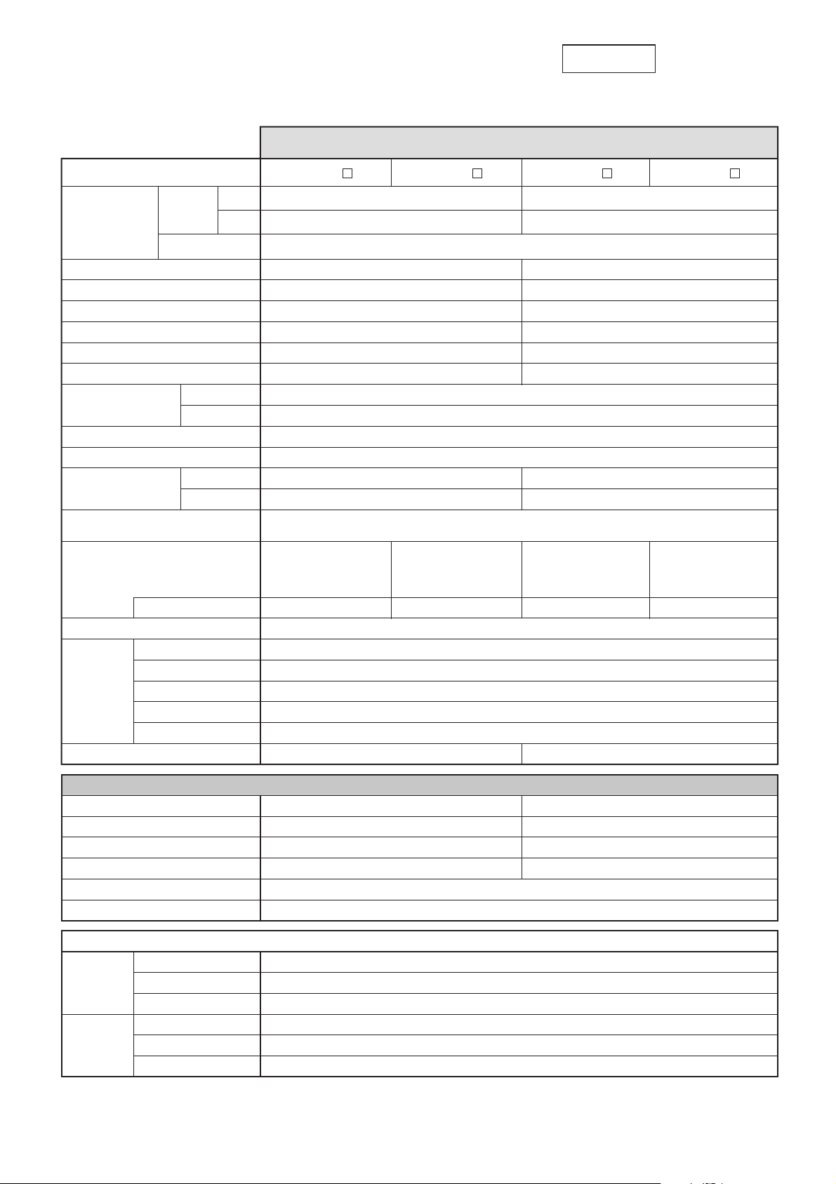
Motor Specifications and Ratings
200V
MDMA
1.0kW to 1.5kW Low inertia, Medium Capacity
AC200V
For motor dimensions, refer to page A4-93 , and for the diver, refer to pages A4-23 and 46.
During assembly
During operation
Environment
Radial load P-direction (N)
Thrust load A-direction (N)
Thrust load B-direction (N)
Radial load P-direction (N)
Thrust load A-direction (N)
Thrust load B-direction (N)
Permissible load
Brake specifications (This brake will be released when it is energized. Do not use this for braking the motor in motion.)
Static friction torque (N . m)
Engaging time (ms)
Releasing time (ms) Note)4
Exciting current (DC) (A)
Releasing voltage
Exciting voltage
2500P/r
Incremental
2500P/r
Incremental
17-bit
Absolute/
Incremental
17-bit
Absolute/
Incremental
Protective enclosure rating
Ambient temperature
Ambient humidity
Installation location
Altitude
Vibration resistance
Mass (kg), ( ) represents holding brake type
Rated rotational speed (r/min)
Max. rotational speed (r/min)
Power supply capacity (kVA)
Rated output (W)
Rated torque (N . m)
Momentary Max. peak torque (N . m)
Rated current (Arms)
Max. current (Ao-p)
Motor model
Applicable driver
Resolution per single turn
Rotary encoder specifications
Moment of inertia
of rotor
(x10
-4
kg . m2)
Recommended moment of inertia ratio
of the load and the rotor Note)3
Without brake
With brake
Regenerative brake
frequency
(times/min) Note)1
No limit Note)2
No limit Note)2
Model No.
Frame symbol
A4
series
A4P
series
A4-67
Page 2
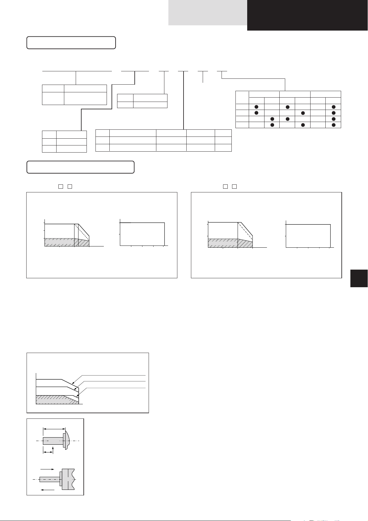
MDMA 1 0 2S1G
Motor structure
Model designation
MDMA series, 1.0kW to 1.5kW
Symbol
MDMA
Type
Middle inertia
(1.0kW-1.5kW)
Symbol
10
15
Rated output
1.0kW
1.5kW
Symbol
P
S
Format
Incremental
Absolute/Incremental
Pulse counts
2500P/r
17-bit
Resolution
10000
131072
Wires
5
7
Rotary encoder specifications
Motor rated output
Symbol2Specifications
200V
Voltage specifications
Design order
1 : Standard
Torque characteristics
at AC200V of power voltage
(Dotted line represents the torque at 10% less supply voltage.)
e.g.)
MDMA102 1
MDMA152 1
0 1000 2000
(2200)
3000
5
10
15
50
0102030
40
100
10
0
20
1000 2000 3000
50
0102030
40
100
(14.4)
(4.8)
(21.5)
(7.15)
torque
[N . m]
Peak run range
rotational speed [r/min] ambient temperature[˚C]
*Continuous torque,
ambient temperature
versus rated torque (%)
Continuous run range
torque
[N . m]
Peak run range
rotational speed [r/min] ambient temperature[˚C]
*Continuous torque,
ambient temperature
versus rated torque (%)
Continuous run range
Note) 1. Regenerative brake frequency represents the frequency of the motor's stops from the rated speed with deceleration without load.
.
If the load is connected, frequency will be defines as 1/(m+1), where m=load moment of inertia/rotor moment of inertia.
.
When the motor speed exceeds the rated speed, regenerative brake frequency is in inverse proportion to the
square of (running speed/rated speed).
.
Power supply voltage is AC230V (at 200V of the main voltage).
If the supply voltage fluctuates, frequency is in inverse proportion to the square of (Running supply voltage/230)
relative to the value in the table.
.
When regeneration occurs continuously such cases as running speed frequently changes or vertical feeding, consult us or
a dealer.
2. If the effective torque is within the rated torque, there is no limit in generative brake.
3. Consult us or a dealer if the load moment of inertia exceeds the specified value.
4. Specified releasing time is obtained with the use of surge absorber for brake (Z15D151 by Ishizuka Electronic or equivalent).
( ) represents the actually measured value using a diode (200V, 1A or equivalent)
A
B
Thrust load (A, B) direction
Radial load (P) direction
L
L/2
P
Shaft
Motor
*When you lower the torque limit setup (Pr5E and 5F), running
range at high speed might be lowered as well.
Torque
rotational speed
Continuous running range
Running range (Torque limit setup : 300%)
Running range (Torque limit setup : 200%)
Running range (Torque limit setup : 100%)
G
H
C
D
Holding brake
with
Oil seal
Symbol
Shaft
without withwithout
Round
Key-way
Products are standard stock items or build to order items. See index (page F31).
MINAS
A4P
A4P
MDMA
1.0kW- 1.5kW
MINAS A4/A4P Motor
A4-68
Page 3

Mod
S
M
Tor
e.g.)
MDMA
15
0
30
(28.5)
(9.54)
torque
[N . m
A
B
Thrust lo
Radial lo
L/2
*When y
range
Torque
Contin
202P1 202S1 302P1 302S1
15.2
16.7
22.3
24.6
3.3
2000
9.54
28.5
12.3
52
4.5
3000
14.3
42.9
17.8
76
Without option
DV0P4285 x 2
MDMA
2000
3000
10000 131072 10000 131072
10.6 (12.5)
16.1
110
50 (130)
0.90
13.7
100
50 (130)
0.79
980
588
686
784
343
343
980
588
686
490
196
196
14.6 (16.5)
MFDDTA390MEDDT7364
MFDDTA390PMEDDT7364P
Frame FFrame E
49m/s
2
or less
10 times or less
IP65 (except shaft through hole and cable end connector)
0 to 40˚C
(free from freezing)
, Storage : –20 to +65˚C (Max.temperature guarantee 80˚C for 72 hours <Nomal temperature>)
85%RH or lower (free from condensing)
Indoors (no direct sunlight), free from corrosive gas, inflammable gas, oil mist and dust
1000m or lower
DC2V or more
DC 24 V ±10%
Motor Specifications and Ratings
200V
MDMA
2.0kW to 3.0kW Middle inertia, Medium Capacity
AC200V
For motor dimensions, refer to page A4-94 , and for the diver, refer to pages A4-24 and 47.
During assembly
During operation
Environment
Radial load P-direction (N)
Thrust load A-direction (N)
Thrust load B-direction (N)
Radial load P-direction (N)
Thrust load A-direction (N)
Thrust load B-direction (N)
Permissible load
Brake specifications (This brake will be released when it is energized. Do not use this for braking the motor in motion.)
Static friction torque (N . m)
Engaging time (ms)
Releasing time (ms) Note)4
Exciting current (DC) (A)
Releasing voltage
Exciting voltage
2500P/r
Incremental
2500P/r
Incremental
17-bit
Absolute/
Incremental
17-bit
Absolute/
Incremental
Protective enclosure rating
Ambient temperature
Ambient humidity
Installation location
Altitude
Vibration resistance
Mass (kg), ( ) represents holding brake type
Rated rotational speed (r/min)
Max. rotational speed (r/min)
Power supply capacity (kVA)
Rated output (W)
Rated torque (N . m)
Momentary Max. peak torque (N . m)
Rated current (Arms)
Max. current (Ao-p)
Motor model
Applicable driver
Resolution per single turn
Rotary encoder specifications
Moment of inertia
of rotor
(x10
-4
kg . m2)
Recommended moment of inertia ratio
of the load and the rotor Note)3
Without brake
With brake
Regenerative brake
frequency
(times/min) Note)1
No limit Note)2
No limit Note)2
Model No.
Frame symbol
A4
series
A4P
series
A4-69
Page 4

MDMA 2 0 2S1G
Motor structure
Model designation
MDMA series, 2.0kW to 3.0kW
Symbol
MDMA
Type
Middle inertia
(2.0kW-3.0kW)
Symbol
20
30
Rated output
2.0kW
3.0kW
Symbol
P
S
Format
Incremental
Absolute/Incremental
Pulse counts
2500P/r
17-bit
Resolution
10000
131072
Wires
5
7
Rotary encoder specifications
Motor rated output
Symbol2Specifications
200V
Voltage specifications
Design order
1 : Standard
Torque characteristics
at AC200V of power voltage
(Dotted line represents the torque at 10% less supply voltage.)
e.g.)
MDMA202 1 MDMA302 1
15
0
30
1000 2000 3000
(2200)
50
0102030
40
100
25
0
50
1000 2000 3000
50
0102030
40
100
(28.5)
(9.54)
(42.9)
(14.3)
torque
[N . m]
Peak run range
rotational speed [r/min] ambient temperature[˚C]
*Continuous torque,
ambient temperature
versus rated torque (%)
Continuous run range
torque
[N . m]
Peak run range
rotational speed [r/min] ambient temperature[˚C]
*Continuous torque,
ambient temperature
versus rated torque (%)
Continuous run range
Note) 1. Regenerative brake frequency represents the frequency of the motor's stops from the rated speed with deceleration without load.
.
If the load is connected, frequency will be defines as 1/(m+1), where m=load moment of inertia/rotor moment of inertia.
.
When the motor speed exceeds the rated speed, regenerative brake frequency is in inverse proportion to the
square of (running speed/rated speed).
.
Power supply voltage is AC230V (at 200V of the main voltage).
If the supply voltage fluctuates, frequency is in inverse proportion to the square of (Running supply voltage/230)
relative to the value in the table.
.
When regeneration occurs continuously such cases as running speed frequently changes or vertical feeding, consult us or
a dealer.
2. If the effective torque is within the rated torque, there is no limit in generative brake.
3. Consult us or a dealer if the load moment of inertia exceeds the specified value.
4. Specified releasing time is obtained with the use of surge absorber for brake (Z15D151 by Ishizuka Electronic or equivalent).
( ) represents the actually measured value using a diode (200V, 1A or equivalent)
A
B
Thrust load (A, B) direction
Radial load (P) direction
L
L/2
P
Shaft
Motor
*When you lower the torque limit setup (Pr5E and 5F), running
range at high speed might be lowered as well.
Torque
rotational speed
Continuous running range
Running range (Torque limit setup : 300%)
Running range (Torque limit setup : 200%)
Running range (Torque limit setup : 100%)
G
H
C
D
Holding brake
with
Oil seal
Symbol
Shaft
without withwithout
Round
Key-way
Products are standard stock items or build to order items. See index (page F31).
MINAS
A4P
A4P
MDMA
2.0kW-3.0kW
MINAS A4/A4P Motor
A4-70
Page 5

M
Mod
S
M
Tor
e.g.)
MDMA
MDMA
25
0
50
(18.8)
(56.4)
torque
[N . m]
torque
[N . m]
A
B
Thrust lo
Radial lo
L/2
*When y
range
Torque
Contin
50
0
100
(119)
P
P
C
C
402P1 402S1 502P1 502S1
42.5
46.8
60.7
66.7
7.5
5000
23.8
71.4
28.0
120.0
94
6.0
4000
18.8
56.4
23.4
100.0
250
Without option
DV0P4285 x 2
MDMA
2000
3000
1500
3000
10000 131072 10000 131072
18.8 (21.3) 25.0 (28.5)
21.5
90
35 (150)
1.10
24.5
80
25 (200)
1.30
1666
784
980
784
343
343
2058
980
1176
1176
490
490
MFDDTB3A2 MGDDTC3B4
MFDDTB3A2P
Frame F Frame G
49m/s2 or less 24m/s2 or less
10 times or less
IP65 (except shaft through hole and cable end connector)
0 to 40˚C
(free from freezing)
, Storage : –20 to +65˚C (Max.temperature guarantee 80˚C for 72 hours <Nomal temperature>)
85%RH or lower (free from condensing)
Indoors (no direct sunlight), free from corrosive gas, inflammable gas, oil mist and dust
1000m or lower
DC2V or more
DC 24 V ±10%
Motor Specifications and Ratings
200V
MDMA
4.0kW to 7.5kW Middle inertia, Medium Capacity
AC200V
For motor dimensions, refer to page A4-95 , and for the diver, refer to pages A4-24,25 and 47.
During assembly
During operation
Environment
Radial load P-direction (N)
Thrust load A-direction (N)
Thrust load B-direction (N)
Radial load P-direction (N)
Thrust load A-direction (N)
Thrust load B-direction (N)
Permissible load
Brake specifications (This brake will be released when it is energized. Do not use this for braking the motor in motion.)
Static friction torque (N . m)
Engaging time (ms)
Releasing time (ms) Note)4
Exciting current (DC) (A)
Releasing voltage
Exciting voltage
2500P/r
Incremental
2500P/r
Incremental
17-bit
Absolute/
Incremental
17-bit
Absolute/
Incremental
752P1 752S1
99.0
105.0
11
7500
48
119
46.6
165.0
No limit Note)2
10000 131072
41.0 (45.0)
58.8
150
50 (130)
1.40
2500P/r
Incremental
17-bit
Absolute/
Incremental
Protective enclosure rating
Ambient temperature
Ambient humidity
Installation location
Altitude
Vibration resistance
Mass (kg), ( ) represents holding brake type
Rated rotational speed (r/min)
Max. rotational speed (r/min)
Power supply capacity (kVA)
Rated output (W)
Rated torque (N . m)
Momentary Max. peak torque (N . m)
Rated current (Arms)
Max. current (Ao-p)
Motor model
Applicable driver
Resolution per single turn
Rotary encoder specifications
Moment of inertia
of rotor
(x10
-4
kg . m2)
Recommended moment of inertia ratio
of the load and the rotor Note)3
Without brake
With brake
Regenerative brake
frequency
(times/min) Note)1
No limit Note)2
No limit Note)2
DV0P4285 x 4
Model No.
Frame symbol
A4
series
A4P
series
A4-71
Page 6

MDMA 4 0 2S1G
Motor structure
Model designation
MDMA series, 4.0kW to 7.5kW
Symbol
MDMA
Type
Middle inertia
(4.0kW-7.5kW)
Symbol
40
50
75
Rated output
4.0kW
5.0kW
7.5kW
Symbol
P
S
Format
Incremental
Absolute/Incremental
Pulse counts
2500P/r
17-bit
Resolution
10000
131072
Wires
5
7
Rotary encoder specifications
Motor rated output
Symbol2Specifications
200V
Voltage specifications
Design order
1 : Standard
Torque characteristics
at AC200V of power voltage
(Dotted line represents the torque at 10% less supply voltage.)
e.g.)
MDMA402 1
MDMA752 1
MDMA502 1
010203040
100
85
70
50
25
0
50
1000 2000 3000
35
0
70
1000 2000 3000
010203040
100
90
85
50
(18.8)
(56.4)
(71.4)
(23.8)
torque
[N . m]
torque
[N . m]
rotational speed [r/min]
rotational speed [r/min]
ambient temperature[˚C]
ambient temperature[˚C]
*Continuous torque,
ambient temperature
*Continuous torque,
ambient temperature
versus rated torque (%)
versus rated torque (%)
with Brake
without Brake
torque
[N . m]
Peak run range
rotational speed [r/min] ambient temperature[˚C]
*Continuous torque,
ambient temperature
versus rated torque (%)
Continuous run range
with Brake
without Brake
Note) 1. Regenerative brake frequency represents the frequency of the motor's stops from the rated speed with deceleration without load.
.
If the load is connected, frequency will be defines as 1/(m+1), where m=load moment of inertia/rotor moment of inertia.
.
When the motor speed exceeds the rated speed, regenerative brake frequency is in inverse proportion to the
square of (running speed/rated speed).
.
Power supply voltage is AC230V (at 200V of the main voltage).
If the supply voltage fluctuates, frequency is in inverse proportion to the square of (Running supply voltage/230)
relative to the value in the table.
.
When regeneration occurs continuously such cases as running speed frequently changes or vertical feeding, consult us or
a dealer.
2. If the effective torque is within the rated torque, there is no limit in generative brake.
3. Consult us or a dealer if the load moment of inertia exceeds the specified value.
4. Specified releasing time is obtained with the use of surge absorber for brake (Z15D151 by Ishizuka Electronic or equivalent).
( ) represents the actually measured value using a diode (200V, 1A or equivalent)
A
B
Thrust load (A, B) direction
Radial load (P) direction
L
L/2
P
Shaft
Motor
*When you lower the torque limit setup (Pr5E and 5F), running
range at high speed might be lowered as well.
Torque
rotational speed
Continuous running range
Running range (Torque limit setup : 300%)
Running range (Torque limit setup : 200%)
Running range (Torque limit setup : 100%)
G
H
C
D
Holding brake
with
Oil seal
Symbol
Shaft
without withwithout
Round
Key-way
Products are standard stock items or build to order items. See index (page F31).
50
0
100
(119)
1000
(1500)
2000 3000
010203040
100
50
Peak run range
Peak run range
Continuous run range
Continuous run range
MINAS
A4P
A4P
MDMA
4.0kW- 7.5kW
MINAS A4/A4P Motor
A4-72
 Loading...