

Page 1
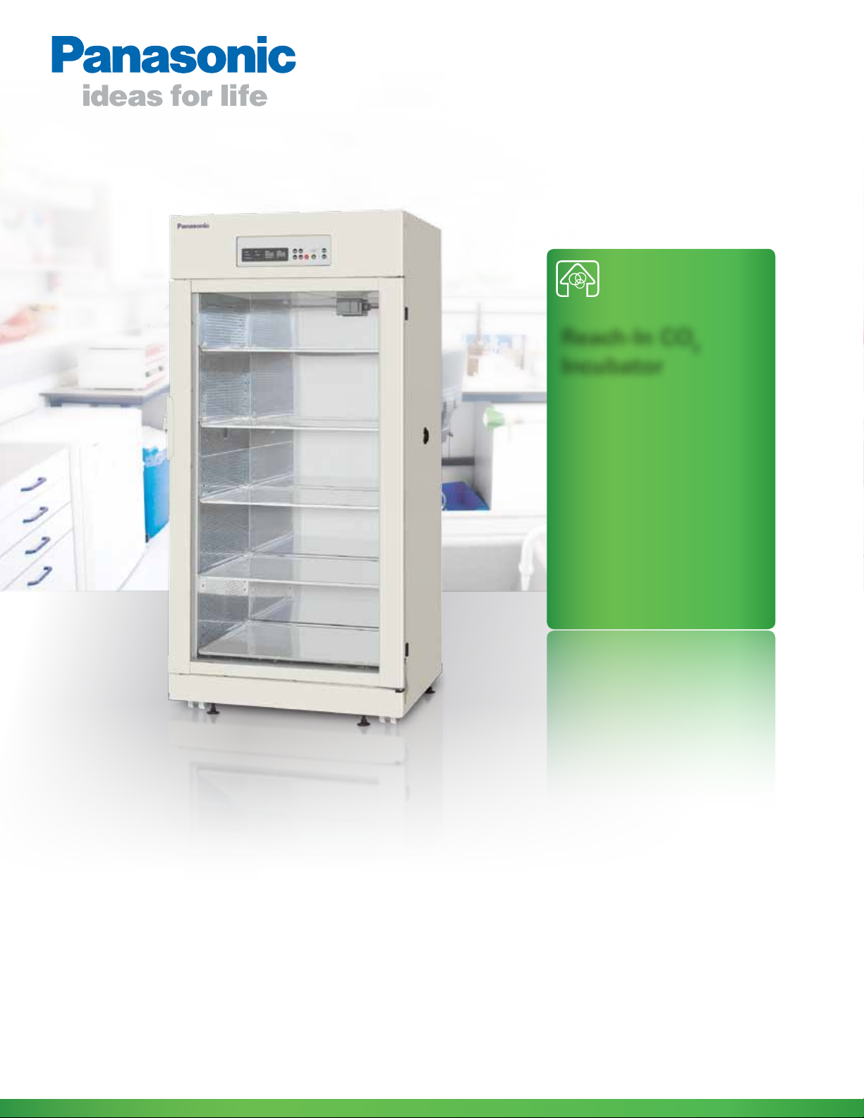
MCO-80IC
Reach-In CO2
Incubator
Features:
• The industry’s most complete cell culture
solution for large volume applications.
• Exceptionally low CO
recovery following door openings.
CO
2
Panasonic… the new name for SANYO
www.panasonic.com/biomedical
consumption with fast
2
Page 2
MCO-80IC
CO2 recovery after a 60 second door opening
for the Panasonic MCO-80IC
Temperature Recovery
5%
4%
3%
2%
1%
10 min. 20 min.
10 min. 20 min.
CO2 recovery after a 60 second door opening
for the Panasonic MCO-80IC
Temperature Recovery
5%
4%
3%
2%
1%
37°C
36°C
35°C
34°C
33°C
10 min. 20 min.
10 min. 20 min.
Reach-In CO2 Incubator
Panasonic’s large capacity, reach-in CO2 incubator has the capacity and flexibility to grow with your
culturing needs while providing a precise and repeatable temperature, humidity and CO
environment.
2
The MCO-80IC is ideal for culturing
large volumes of biological samples,
performing short-term studies, and
working with large volume cell culture
apparatus. It includes Panasonic’s
exclusive incubator technologies such as
inCu-saFe
®
interiors, UV decontamination option, infrared (IR) CO
P.I.D. control, and features exceptionally
low CO
gas consumption.
2
Superior CO2 and
Temperature Control
• IR CO2 sensor with P.I.D. microproces-
sor control and forced air circulation
system delivers fast CO
characteristics.
• Exceptionally low CO
tion rates, less than half of similar
competitive units.
• P.I.D. temperature control with
deviation of ±0.1°C.
sensor with
2
recovery
2
gas consump-
2
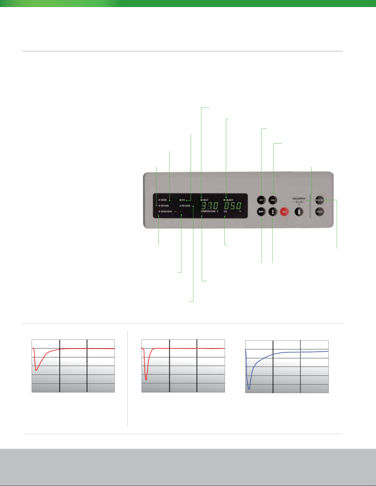
UV Decontamination –
Light Indicator
Open Door Indicator
Water Reservoir
Level Indicator
Secondary Over
Temp. Indicator
Over Temp. Safety
Shut off Adjustment
High Humidity Mode Indicator
Heater On
Indicator
CO
Inject Indicator
2
CO
Display
2
Scroll Programming Buttons
Temperature Display
Setpoint – Set Temperature and CO
Calibration - Calibrate chamber
temperature and CO
2
Optional Built-in CO
Tank Switchover System
Alarm, Buzzer
Silence
2
2
Panasonic MCO-80IC
Recovery after a 30 second door opening for the
Panasonic MCO-80IC.
2 MCO-80IC Reach-In Incubator www.panasonic.com/biomedical
CO2 recovery after a 60 second door opening
for the Panasonic MCO-80IC
5%
4%
3%
2%
1%
10 min. 20 min.
CO2 recovery after a 60 second door opening
for the competitor
5%
4%
3%
2%
1%
10 min. 20 min.
Panasonic MCO-80IC Competitor
Faster CO2 Recovery and lower CO2 Consumption after 60 second door opening.
Page 3

Anti-Contamination Measures
• Interior, plenums and shelving
constructed of Panasonic’s exclusive
inCu-saFe
enriched stainless steel.
• Optional UV decontamination system
for humidity reservoir.
• Extra heaters positioned around
the outer glass door to eliminate
condensation.
®
, germicidal, copper-
Horizontal Laminar
Airow System
Panasonic’s reach-in incubator’s crossshelf directed air ow system promotes
optimum temperature uniformity
throughout the chamber and contributes
to quick temperature recovery after door
openings. Utilizing Panasonic’s exclusive inCu-saFe
perforated side plenums helps minimize
contamination concerns and direct positive and negative pressure air ow.
Humidied air minimizes potential for cell culture
media desiccation.
Perforated sidewall panels right (pressure) and left
(negative pressure) assure a positive, gentle airow
from right to left.
Access ports (each side, 40mm).
®
chamber material in the
Optional UV Decontamination
and Humidity Selection
Panasonic’s patented Safe Cell UV
decontamination system is employed to
decontaminate the humidifying water
reservoir and help eliminate contamination concerns. The unit can be set to both
nominal (above 80% RH) and high humidity setpoints (above 90% RH).
Humidity reservoir heaters are located
on the outside walls of the reservoir
and are not as susceptible to corrosion
and scaling from water as competitive
systems are. An optional autofill secondary tank (Model MCO-80AS) system is
also available to ensure continuous
water supply to the humidity reservoir.
This system employs a large tank
(4.8 gal./18 L), with electronic water level
sensor and autofill solenoid valve.
Optional Shaker shelves with additional support
available in 2 or 3 shelf congurations.
Horizontal airow maintains accurate temperature
and CO2 control and uniformity at all shelf levels,
top-to-bottom, front-to-back.
Optional SafeCell UV decontamination system provides
decontamination of the humidity reservoir.
Optional Accessories
Option Code
MCO-80GC-P W Built in gas automatic switcher kit
MCO-80RBS-PW Roller bot tle apparatus mounting ramp kit
MCO-80ID-PW Inner Door Kit 5 partition doors, made with acrylic resin
MCO - 80 UV S- PA UV sterilization of humidifying water reservoir only
MCO-80AS-PW
MCO -80S T-P W Additional shelf
MCO-420MA-PW 4 to 20 mA analog output module
MCO-10 0L CO
MCO-80IC3RSLF Reinforced shelves for shaker use
Automatic water supply system: Includes control box,
water tank, water supply hose, 18L (4.8 gallon) tank
tank regulator
2
3
Page 4

Specications
MCO-80IC-PA
Dimensions
Overall Exterior Dimensions (w x f- b x h) 33.8” × 33.6” × 8 0.3” / 986 × 853 × 2040 mm
Interior Dimensions (w x f- b x h) 31.7” × 27.3 " × 60.0” / 806 × 693 × 1524 mm
Interior Volume 30.1 cu.ft / 851 L
Shelving (w x f-b x h)
Construction
Exterior Cabinet Electrogalvanized Steel (Acr ylic resin baking painted nish)
Interior Cabinet Copper Alloy Stainless Steel (expect humidif ying reser voir)
External Door Double Paned Glass Door with out door latch
Shelving Copper alloy Stainless Steel (5 standard)
Net Unit weight 605 lbs. / 275 kg.
Access Ports 40 mm(1.57”), 2 locations (right and left sides) with silicone rubber stopper)
Environmental Performance
Temperature Control Range
Temperature Uniformity Deviation ±0. 5°C (in 25°C ambient, setting 37° C, 5% CO
Temperature Fluctuation Margin
Control Range 0 to 20% ± 0.15%, no load
CO
2
Chamber Humidity Over 80% RH (High humidit y mode: over 90% RH)
30.5” x 25. 9” x 0.4” / 776 x 659 x 10 mm
Load Capacity: 66 lbs. / 30 kg
+5°C above ambient to 50°C (in a 20 °C to 35°C ambient )
, no load 9 point measurement)
2
±0.1% (in 25°C ambient, setting 37°C, 5% CO
, no load )
2
Environmental Controls
Humidifying Reservoir Integrated with an inner chamber (Stainless Steel, SUS30 4)
Humidif ying Method Heated vaporization with water in humidity pan (High humidit y mode available)
High Humidity Mode Selectable by function mode (for over 90%RH)
Humidif ying Water Retention Days (Reference)
(Under a condition of 25°C ambient, setting 37°C, 5% CO
15 days (Reference)
, no load, no door opening, 80 %RH )
2
Heating Method Heater with fan air circulation, cross shelf laminar air ow
Temperature Control System
Temperature Display
Water Drainage
Microprocessor P.I.D. with thermistor sensor, temperature uctuation of + 0 .1° C
Digital display (0.1°C increments)
Drainage valve (lower side of front frame)
Drainage into a tray/bottle (provided)
Water Fill Water ll located at the front side of interior bottom (optional autoll)
CO
Gas Control
2
Gas Inlet Pressure
CO
2
Microprocessor P.I.D. with infrared sensor (0.1% increments)
15 psi (0.1 MPa)
Electrical
Power Requirements 115V, 20 Amps, 60 Hz, NEMA 5-20P Plug
Interior/Exterior Convenience Receptacle Interior Duplex: Vapor Proof. 115V, 3 Amps Max. Rating - Ex terior Duplex:115V, 1 Amp. Max Rating
Alarms
High/ Low Temperature Alarm. CO
Upper limit temperature Alarm. Door Ajar Alarm, Self Diagnostics
density alarm.
2
Remote Alarm Contacts N.O. (normally open) and N.C. (normally closed) contacts included, rating DC 30 v, 2A
Panasonic Healthcare Company of North America
1300 Michael Drive, Suite A, Wood Dale, IL 60191
Toll Free USA (800) 858-8442, Fax (630) 238-0074
www.panasonic.com/biomedical
© Panasonic Printed in USA 2012.02 JB
JB201202V1
 Loading...