

Panasonic MCO-230AIC, MCO-230AICUV, MCO-230AICUVH, MCO-170AICL, MCO-170AICUVHL Operating Instructions Manual
...
Please read the operating instructions carefully before using this product, and save the operating
instructions for future use.
See page 96 for all model numbers.
MCO-230AIC
MCO-230AICUV
MCO-230AICUVH
Series
CO2 Incubator
Operating Instructions
MCO-230AIC
MCO-230AICUV
MCO-230AICUVH


1
CONTENTS
INTRODUCTION P. 3
INTENDED USE AND PRECAUTIONS P. 3
PRECAUTIONS FOR SAFE OPERATION P. 4
LABELS ON INCUBATOR P. 8
SYMBOLS ON INCUBATOR P. 9
ENVIRONMENTAL CONDITIONS P. 9
INCUBATOR COMPONENTS
Unit P. 10
LCD touch panel P. 12
Remote alarm terminal P. 14
INSTALLATION
Installation site P. 15
Installation P. 17
Connecting CO
2
gas cylinder P. 20
BEFORE COMMENCING OPERATION
Initial cleaning method P. 21
Removing inner attachments P. 22
Installing inner attachments P. 24
Filling humidifying pan P. 25
FOR BETTER CULTIVATION
Precautions for cultures P. 26
Preventing contamination P. 27
CORRECT OPERATION P. 28
BASIC OPERATION ON LCD TOUCH PANEL P. 29
BASIC PARAMETERS
Numerical input to input window P. 31
Setting temperature, CO2 density and high limit temperature alarm
P. 32
Setting key lock P. 34
Removing key lock P. 36
ALARM PARAMETERS P. 38
OPERATION/ALARM LOG
Setting log interval P. 41
Displaying operation log P. 42
Exporting operation log P. 45
Displaying alarm log P. 48
Exporting alarm log P. 50
OTHER PARAMETERS
Setting date and time P. 53
Setting brightness and sleep P. 54
Setting DAQ P. 56

2
CONTENTS
UV LAMP PARAMETERS P. 57
Using UV lamp P. 57
Setting UV lamp ON period P. 58
Lighting UV lamp for 24 hours P. 60
H
2O2
DECONTAMINATION P. 62
H
2O2
decontamination P. 63
Precautions when handling H
2O2
reagent P. 67
Using unlock key P. 67
ELECTRIC LOCK (OPTION) P. 68
Setting User-ID P. 68
Setting auto lock P. 70
Using unlock key P. 73
Removing auto lock P. 74
GAS AUTO CHANGER (OPTION) P. 75
Connecting CO
2
gas cylinder P. 75
Automatic CO
2
gas supply line changeover P. 76
Manual CO
2
gas supply line changeover P. 78
STD GAS AUTO CALIBRATION KIT (OPTION) P. 79
ROUTINE MAINTENANCE P. 82
ALARMS, SAFETY, AND SELF-DIAGNOSIS P. 83
TROUBLESHOOTING P. 86
DISPOSAL OF UNIT P. 89
SPECIFICATIONS P. 94
PERFORMANCE P. 96
SAFETY CHECK SHEET P. 97
3
INTRODUCTION
■ Read the operating instructions carefully before using the Product and follow the instructions for safety
operation.
■ Our company disavows any responsibility for safety if the Product is used for other than the intended use
or used with any procedures other than those given in the operating instructions.
■ Keep the operating instructions in a suitable place so that it can be referred to as necessary.
■ The contents of the operating instructions are subject to change without notice for improvement of
performance or functions.
■ Contact our sales representative or agent if any page of the operating instructions is lost or the page
order is incorrect.
■ Contact our sales representative or agent if any point in the operating instructions is unclear or if there
are any inaccuracies.
■ No part of the operating instructions may be reproduced in any form without the expressed written
permission of our company.
CAUTION
Our company guarantees the product under certain warranty conditions. Our company in no
way shall be responsible for any loss of content or damage of content.
INTENDED USE AND PRECAUTIONS
This equipment is designed for culture of cell tissues, organs, embryos.
■ The adapted culture condition depends on the sample kind. It is necessary to determine the culture
temperature, CO
2
density and culture period suitable for the purpose.
■ For the embryos, the low O
2
density should be better for culture. It is recommended to use O2/CO
2
Incubator.
■ For IVF/ART purpose, special attention should be paid to traceability since incidents might be disclosed
several months or years later, at the baby’s birth or even later during its life. Therefore we recommend to
maintain the following data; product serial number, incubation term and incubation parameters.
(Refer to details on MEDDEV 2.2/4)
4
PRECAUTIONS FOR SAFE OPERATION
It is imperative that the user complies with the operating instructions
as it contains important safety advice.
Items and procedures are described so that you can use this unit correctly and safely. If
the precautions advised are followed, this will prevent possible injury to the user and any
other person.
Precautions are illustrated in the following way:
WARNING
Failure to observe WARNING signs could result in a hazard to personnel
possibly resulting in serious injury or death.
CAUTION
Failure to observe CAUTION signs could result in injury to personnel and
damage to the unit and associated property.
Symbol shows;
This symbol means caution.
T
his symbol means an action is prohibited.
T
his symbol means an instruction must be followed.
Be sure to keep the operating instructions in a place accessible to users of this unit.
< Label on the unit >
This mark is labeled on the cover in which the electrical components of high voltage are
enclosed to prevent the electric shock.
The cover should be removed by a qualified engineer or a service personnel only.
WARNING
As with any equipment that uses CO2 gas, there is a likelihood of oxygen depletion in the vicinity
of the equipment. It is important that you assess the work site to ensure there is suitable and
sufficient ventilation. If restricted ventilation is suspected, then other methods of ensuring a
safe environment must be considered. These may include atmosphere monitoring and warning
devices.
5
Do not use the unit outdoors. Current leakage or electric shock may result if the unit is exposed to
rain water.
Only qualified engineers or service personnel should install the unit. The installation by
unqualified personnel may cause electric shock or fire.
Install the unit on a sturdy floor and take an adequate precaution to prevent the unit from
turning over. If the floor is not strong enough or the installation site is not adequate, this may result in
injury from the unit falling or tipping over.
Never install the unit in a humid place or a place where it is likely to be splashed by water.
Deterioration of the insulation may result which could cause current leakage or electric shock.
Never install the unit in a flammable or volatile location. This may cause explosion or fire.
Never install the unit where acid or corrosive gases are present as current leakage or electric
shock may result due to corrosion.
Always ground (earth) the unit to prevent electric shock. If the power supply outlet is not
grounded, it will be necessary to install a ground by qualified engineers.
Never ground the unit through a gas pipe, water main, telephone line or lightning rod. Such
grounding may cause electric shock in the case of an incomplete circuit.
Connect the unit to a power source as indicated on the rating label attached to the unit. Use of
any other voltage or frequency other than that on the rating label may cause fire or electric shock.
Never store volatile or flammable substances in this unit if the container cannot be sealed. These
may cause explosion or fire.
Do not insert metal objects such as a pin or a wire into any vent, gap or any outlet on the unit.
This may cause electric shock or injury by accidental contact with moving parts.
Use this unit in safe area when treating the poison, harmful or radiate articles. Improper use
may cause bad effect on your health or environment.
Turn off the power switch (if provided) and disconnect the power supply to the unit prior to any
repair or maintenance of the unit in order to prevent electric shock or injury.
Do not touch any electrical parts (such as power supply plug) or operate switches with a wet
hand. This may cause electric shock.
WARNING
6
PRECAUTIONS FOR SAFE OPERATION
Ensure you do not inhale or consume medication or aerosols from around the unit at the time of
maintenance. These may be harmful to your health.
Never splash water directly onto the unit as this may cause electric shock or short circuit.
Never put containers with liquid on the unit as this may cause electric shock or short circuit when
the liquid is spilled.
Never bind, process, or step on the power supply cord, or never damage or break the power
supply plug. A broken supply cord or plug may cause fire or electric shock.
Do not use the supply cord if its plug is loose. Such supply cord may cause fire or electric shock.
Never disassemble, repair, or modify the unit yourself. Any such work carried out by an
unauthorized person may result in fire, or electric shock or injury due to a malfunction.
Disconnect the power supply plug if there is something wrong with the unit. Continued
abnormal operation may cause electric shock or fire.
When removing the plug from the power supply outlet, grip the power supply plug, not the cord.
Pulling the cord may result in electric shock or fire by short circuit.
Disconnect the power supply plug before moving the unit. Take care not to damage the power cord.
A damaged cord may cause electric shock or fire.
Disconnect the power plug when the unit is not used for long periods. Keeping the connection
may cause electric shock, current leakage, or fire due to the deterioration of insulation.
If the unit is to be stored unused in an unsupervised area for an extended period, ensure that children
do not have access and that doors cannot be closed completely.
The disposal of the unit should be accomplished by appropriate personnel. Remove doors to
prevent accidents such as suffocation.
Do not put the packing plastic bag within reach of children as suffocation may result.
Use the reagent specified by our company for H
2O2
decontamination. Using a different H2O2
solution may result in explosion or damage to the incubator.
When performing H
2O2
decontamination, securely close the internal and external doors. Failure to
do so may be harmful to health due to leakage of H
2O2
gas.
During H
2O2
decontamination, plug the access hole with the silicon cap that is provided. Failure to
do so may be harmful to health due to leakage of H
2O2
gas.
Always use the removal power supply cord that is provided. Other power supply cord may cause
electric shock or fire.
WARNING
7
Do not position this unit and the other unit so that it is difficult to operate the disconnection of
the power supply plug. Failure to disconnect the power supply plug may cause fire if there is
something wrong with the unit.
This unit must be plugged into a dedicated circuit protected by branch circuit breaker.
Use a dedicated power source as indicated on the rating label attached to the unit. A multiple-tap may
cause fire resulting from abnormal heating.
Never store corrosive substances such as acid or alkali in this unit if the container cannot be
sealed. These may cause corrosion of inner components or electric parts.
Check the setting when starting up of operation after power failure or turning off of power
switch. The stored items may be damaged due to the change of setting.
Be careful not to tip over the unit during movement to prevent damage or injury.
Prepare a safety check sheet (copy the last page) when you request any repair or maintenance for
the safety of service personnel.
Wear rubber gloves when handling the H
2O2
reagent. Direct contact with the H2O2 reagent may
result in inflammation of the skin.
H
2O2
decontamination can be performed only for the chamber and chamber attachments with standard
specifications, and not for any other objects.
Perform H
2O2
decontamination with the chamber attachments arranged as specified by our
company. Arranging them in a different way may result in insufficient decontamination.
After H
2O2
decontamination has been completed, wear rubber gloves and use a non-woven cloth to
wipe off the residual H
2O2
fluid from the bottom of the chamber, any objects that were
decontaminated, and the bottoms of ducts.
CAUTION
WARNING
8
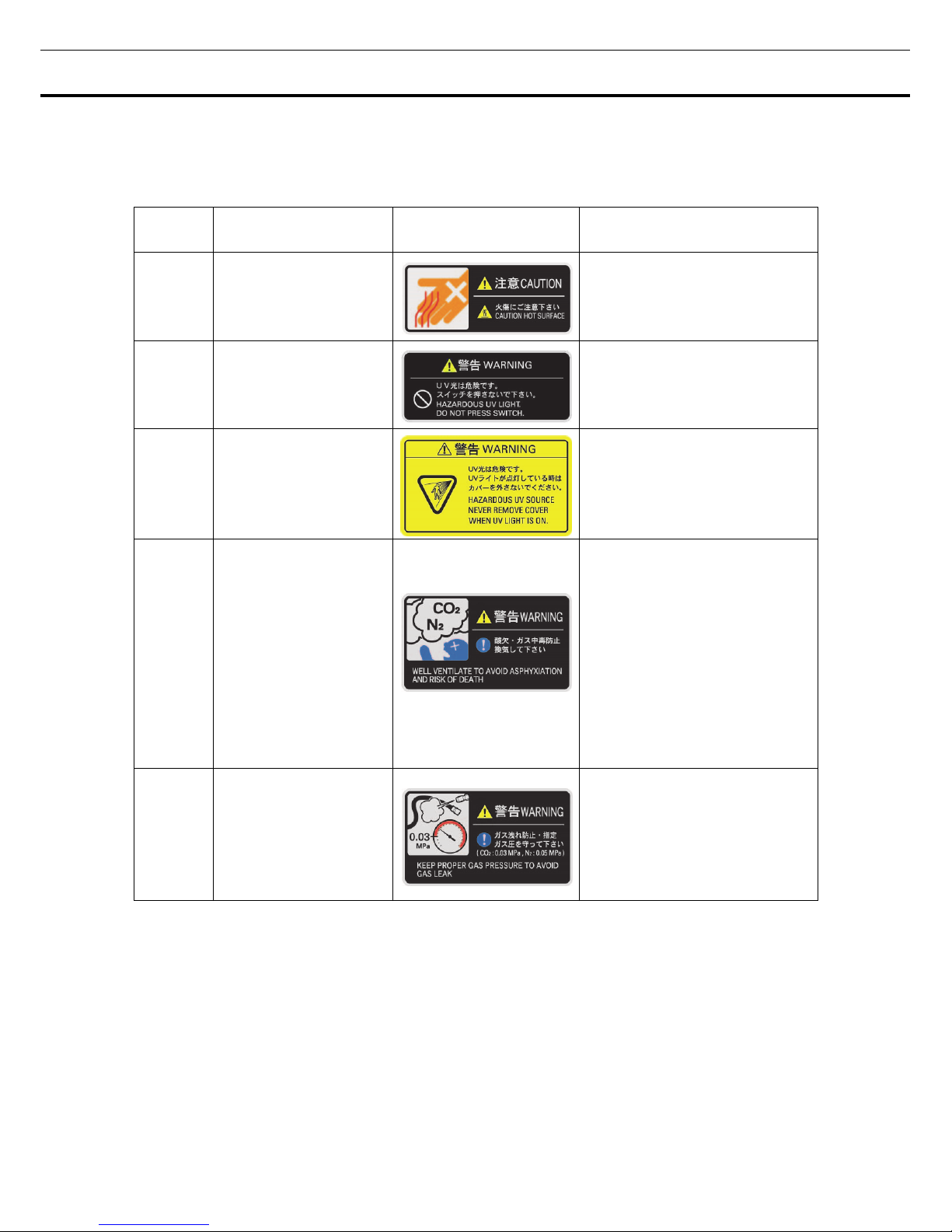
LABELS ON INCUBATOR
Warning Safety Labels Applied to the Incubator
Users are advised to avoid accidents by carefully reading the warnings and cautions contained on warning
stickers at key locations on the interior and exterior of the incubator.
Possible
Danger
Warning/Caution Type
Location of Danger
Warning/Caution Label Description of Danger
Burns
Hot Surface
Cooling Unit &
Heat Cover
Avoid touching the cooling unit
and heat cover, which reaches
high temperatures and may cause
burns.
Personal
injury
Hazardous UV Light
Interior
The UV lamp lights by pressing
the door switch. Do not press the
door switch because the UV light
is hazardous.
Personal
injury
Hazardous UV Light
Interior
The UV light is hazardous.
Never turn on the UV lamp without
the cover.
Personal
injury
Gas Poisoning or
Oxygen Deprivation
Environment
When using CO
2
gas for control,
make sure that there is
adequate ventilation. Using
CO
2
gas in a small room without
adequate ventilation may cause
gas poisoning or oxygen
deprivation. In addition, when
opening the Incubator doors, do
not directly inhale the air in the
chamber.
Personal
injury
Gas Poisoning or
Oxygen Deprivation
Interior
Excessive pressure may cause
gas supply lines inside the
Incubator to come loose, which
may result in gas poisoning or
oxygen deprivation due to the
escaping of gas.
9
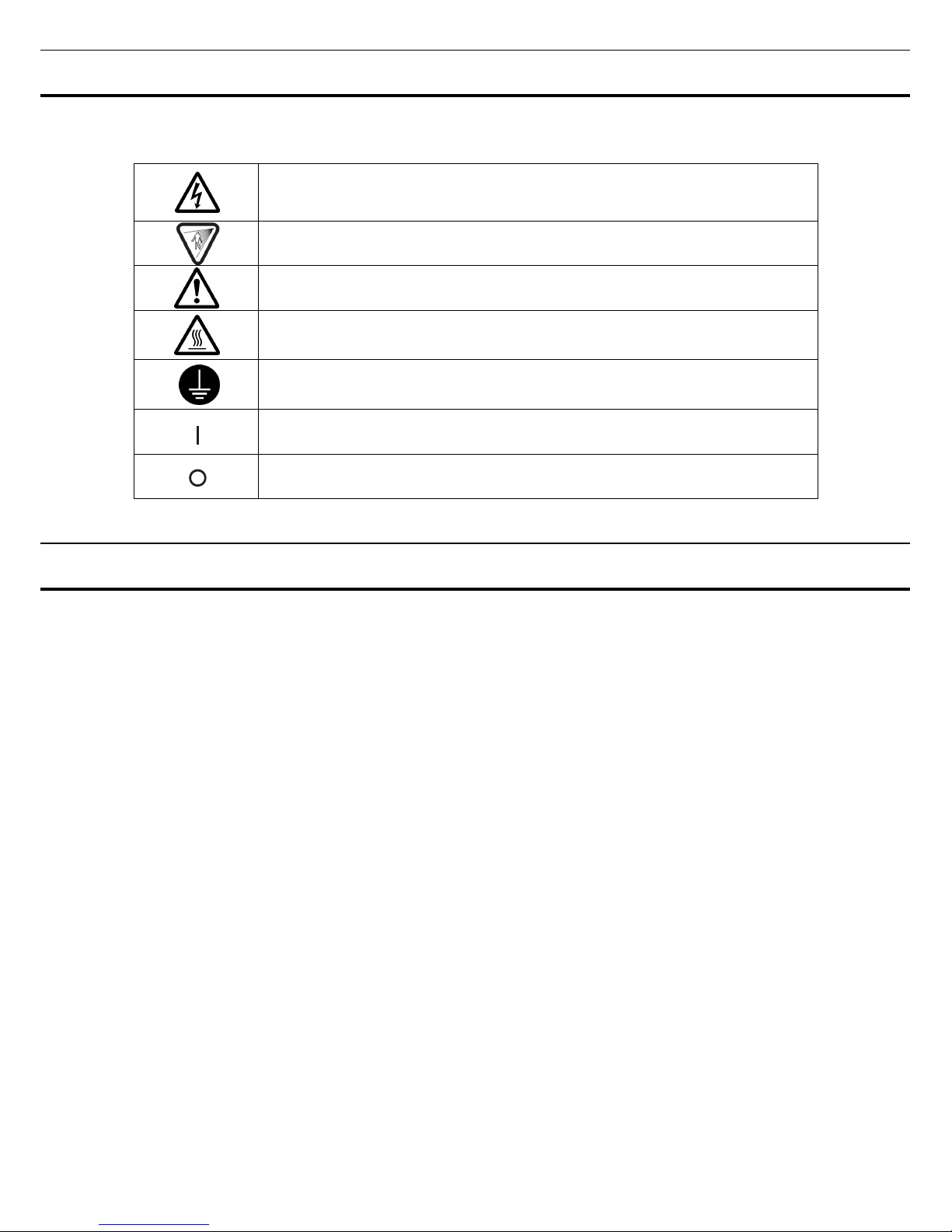
SYMBOLS ON INCUBATOR
The symbols are attached to the incubator. The following table describes the symbols.
This symbol is attached to covers that access high-voltage electrical components to
prevent electric shock. Only a qualified engineer or service personnel should be
allowed to open these covers.
This symbol indicates an ultraviolet light (UV) caution.
This symbol indicates that caution is required. Refer to product documentation for
details.
This symbol indicates a hot surface.
This symbol indicates an earth.
This symbol means “ON” for a power switch.
This symbol means “OFF” for a power switch.
ENVIRONMENTAL CONDITIONS
This equipment is designed to be safe at least under the following conditions (based on the IEC-61010-1):
■ Indoor use;
■ Altitude up to 2000 m;
■ Temperature 5
o
C to 40oC
■ Maximum relative humidity 80% for temperature up to 31
o
C decreasing linearly to 50% relative humidity
at 40
o
C;
■ Mains supply voltage fluctuations up to ±10% of the nominal voltage;
■ Transient overvoltages up to the levels of OVERVOLTAGE CATEGORY Ⅱ;
■ Temporary OVERVOLTAGES occurring on the mains supply;
■ Applicable pollution degree of the intended environment (POLLUTION DEGREE 2 in most cases);
10
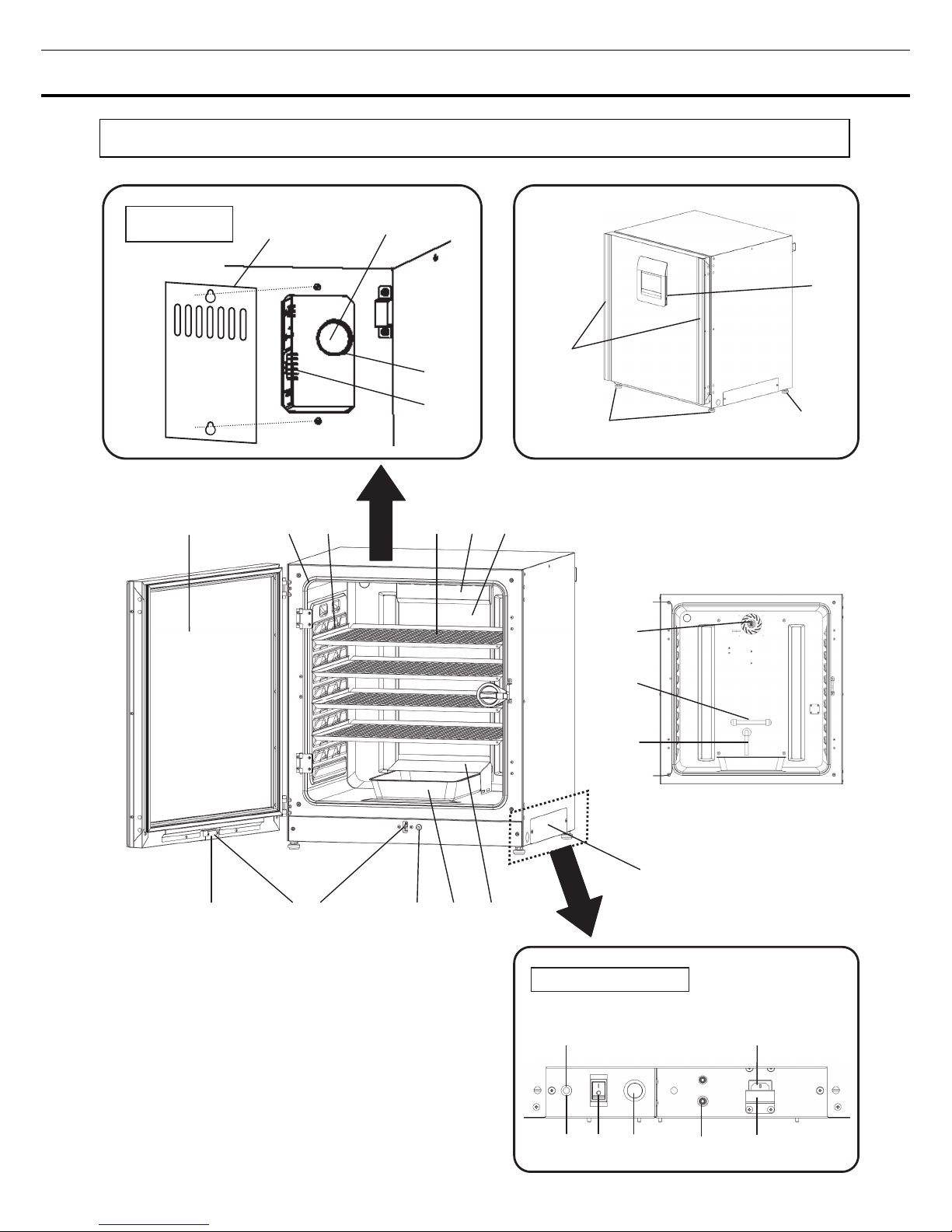
INCUBATOR COMPONENTS
Unit
1 2 3 Tray 4 5
6
7*
1
8
13
12*
2
Electric key*2 11 10 9
*1: MCO-230AICUVH/230AICUV or when an
optional UV system set MCO-170UVS is installed.
*2: MCO-230AICUVH or when an optional electric
lock MCO-170EL is installed.
(When some inner
attachments are removed)
19
Leveling
feet
Leveling
Foot
Handles
(When 13 is removed)
Sample air outlet cap
18 17 16*
1
15 14
Removal power
supply cord port
Lower right side
20
21
Access port
cover
Silicon cap
Rear left

11
1. Outer door: The outer door is held to the frame with the magnetic seal. The door heater is installed in
the door panel. The door opening is reversible. Contact our sales representative or agent to change the
door hinge from left to right or vice versa.
2. Inner door: The inner door is made of tempered glass. However do not subject the glass to excessive
impacts.
3. Tray catches: Insert tray to fit the concave portion on chamber.
4. Fan cover: The fan cover serves as the inlet for circulating air. It is removable.
5. Duct: The duct for the path for circulating air. It is removable.
6. Fan (inside the duct): The fan is made from polypropylene resin. It can be disinfected in an autoclave.
7. UV lamp*
1
: This UV lamp does not generate ozone. Never look directly at the UV light. Refer to page 57
~61 for using. For replacement, contact our sales representative or agent.
8. Humidity control bar: Reduce automatically dew condensation occurred by the effect of outside
environment and the frequency of door opening/closing.
The humidity control bar has bactericidal effects by plated surface of it. However, it is recommended to
replace the humidity control bar every 5 to 6 years to maintain bactericidal effects. (The duration
of bactericidal effects differs depending on the use environment.)
9. Humidifying pan cover: This cover prevents the UV light entering the chamber. Always use it. Using
without it may have a bad influence on the chamber temperature distribution and humidity recovery.
10. Humidifying pan: Fill the humidifying pan with sterile distilled water, and set the humidifying pan with
the inner side flush against the back. Install the humidifying pan in a longitudinal direction as its shorter
side is placed in the back.
11. Door switch: Detects the door opening/closing and stops the fan and electromagnetic valve for CO
2
when the door is open. The UV lamp*
1
is also deactivated by the door opening.
12. Key hole*
2
: This is the hole to unlock with unlock key while outer door is locked by electric lock.
13. Switch cover: Prevent the accident of gas tube disconnected by the unexpected touch or power off.
14. Power supply cord cover plate: This plate is to prevent the power cord being come off.
15. Connecting port A for CO
2
gas pipe: Refer to page 20 for gas cylinder connection. Ensure that the
gas pressure is set at 0.03 MPa(G) (0.3 kgf/cm
2
(G), 4.4 psi(G)).
Note: When the optional MCO-21GC gas auto changer is installed, both ports A and B are available. Refer
to page 75 for gas auto changer.
16. Glow starter*
1
: The glow is started for the UV lamp.
17. Power switch: This is the main switch for the incubator. It also functions as an overcurrent breaker.
18. Sample air outlet: The sample air outlet also functions as an internal gas outlet. Normally, cover this
outlet with the sample air outlet cap.
19. USB port: Insert USB memory to export operations and alarms log. Refer to page 41~52.
Note: It is impossible to use USB memory which is required password input.
20. Access port: Place the silicon caps on both outside and inside of the port when the port is not being
used.
21. Remote alarm terminals: This terminal informs the alarm to remote location by connecting to external
alarm unit. Refer to page 14.
12
INCUBATOR COMPONENTS
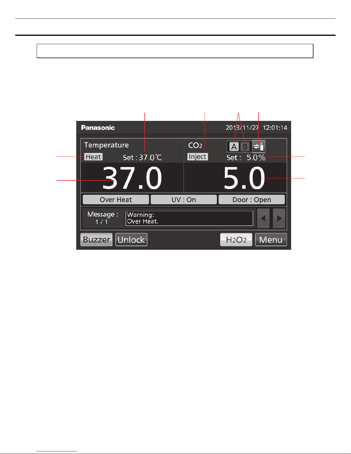
LCD touch panel
The following display (called the Top screen) will appear when the power switch is turned ON.
Note: It takes approximately 20 seconds until Top screen is displayed. During warming-up, “Status: Gas
sensor initializing” is displayed in the Message display field (13), and “--.-” is displayed in the Present CO
2
density display field (4).
2 6 7 8
3
1
1. Present temperature display field
The current chamber temperature is displayed.
2. Set temperature value display field
The set value of chamber temperature is
displayed. Default setting: 37
o
C.
3. Heating indicator
This lamp lights when the heater is energized.
4. Present CO
2
density display field
The current chamber CO
2
density is displayed.
Nothing is displayed when CO
2
density is set 0 %.
5. Set CO
2
density value display field
The set value of the chamber CO
2
density is
displayed. Default setting: 0 %.
6. CO
2
gas injection indicator
This lamp lights when CO
2
gas is being
injected.
7. CO
2
gas supply line indicator A and B*1
Current supplying CO
2
gas supply line
(connecting port for CO
2
gas pipe) is
displayed. The connecting port A/B for gas
pipe that is currently supplying CO
2
is
displayed in reverse video and blinks.
8. CO
2
gas supply line select key*1
This is a key to select CO
2
gas supply line A
or B (Connecting port A or B for CO
2
gas
pipe). When an optional gas auto charger
MCO-21GC is installed, CO
2
gas supply line
A/B changes over automatically when CO
2
gas cylinder is empty. Changeover is also
workable by pressing this key.
*1: Only when an optional component MCO-21GC (Gas auto charger) is installed, this key is workable. They
are not displayed when the MCO-21GC is not installed.
5
4
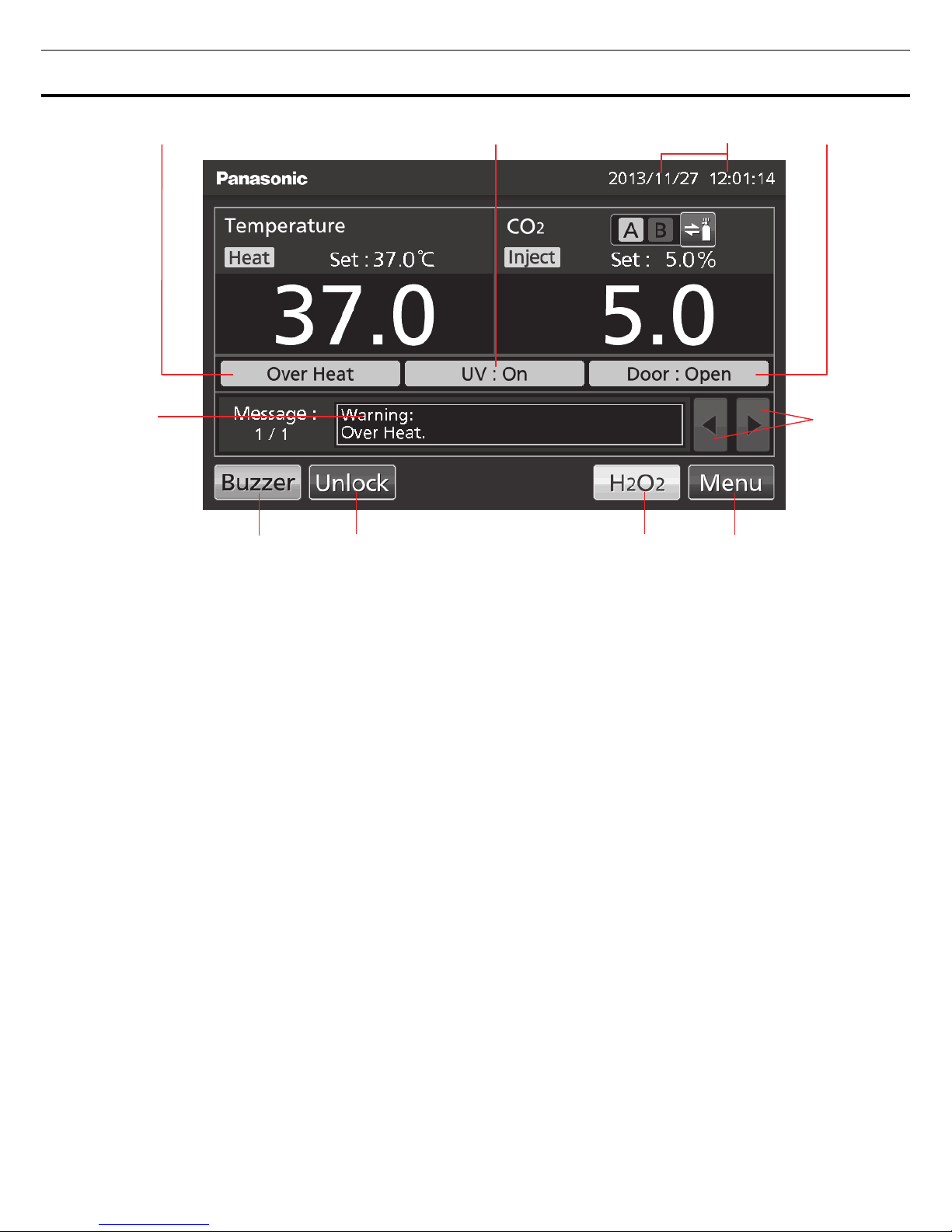
13
10 11 9 12
13
18 17 16 15
9. Present date/time display field
Normally, this indicator shows date and time.
The date and time is simply set when the
incubator is shipped from the factory. Refer to
page 53 for details.
10. Over heat display
High limit temperature alarm is activated:
“Over Heat” is displayed alternately in normal
characters and reverse video.
11. UV lamp condition display
UV lamp ON: “UV : On” is displayed.
UV lamp OFF: “UV : Off” is displayed.
Note: Nothing is displayed when an optional
UV system set MCO-170UVS is not installed
to the MCO-230AIC.
12. Outer door (opening/closing) display
Open: “Door : Open” is displayed alternately
in normal characters and reverse video.
Close: “Door : Closed” is displayed.
Locked: “Door : Locked” is displayed.*
2
13. Message display field
Alarms, errors or messages are displayed
when fault occurs. Refer to page 83~85.
Note: When there are a number of
alarms/errors, the display shows the message.
For example, if 2 alarms/errors occur in total,
the display shows “1/2”.
14. Message select key
When there are a number of alarm/errors, the
message on the screen is changeable.
15. Menu key
Press this key to lead the Menu screen. It is
possible to set various setting on the Menu
screen. Refer to page 29.
*2: Auto lock function by electric lock is workable under any of the following conditions. When the condition
is not fulfilled, “Door : Locked” or Unlock key are not displayed.
・MCO-230AICUVH ・When an optional electric lock MCO-170EL is installed.
14
14
INCUBATOR COMPONENTS
16. H
2O2
key*3
This key is to run H
2O2
decontamination. Refer
to page 62 to 67.
17. Unlock key*
2
Press this key is to unlock the outer door when
it is auto-locked by electric lock. Refer to page
72. When the auto lock function is OFF, this
key is not displayed.
18. Buzzer key
Press this key to silence the buzzer. However,
when the ring back is ON, the buzzer will
sound again when the ring back passed and
the alarm state still continues. Refer to page
39~40 and 83~85.
Note: It is not possible to silence the buzzer
for the high limit temperature alarm.
*3: The H
2O2
decontamination function is workable under any of the following conditions. When the
condition is not fulfilled, the H
2O2
key is not displayed on the LCD touch panel.
・When an H
2O2
generator MCO-HP is installed in the MCO-230AICUVH.
・When all H
2O2
generator MCO-HP, H2O2 decon board MCO-170HB and electric lock MCO-170EL are
installed in the MCO-230AICUV.
・When all UV system set MCO-170UVS, H
2O2
generator MCO-HP, H2O2 decon board MCO-170HB and
electric lock MCO-170EL are installed in the MCO-230AIC.
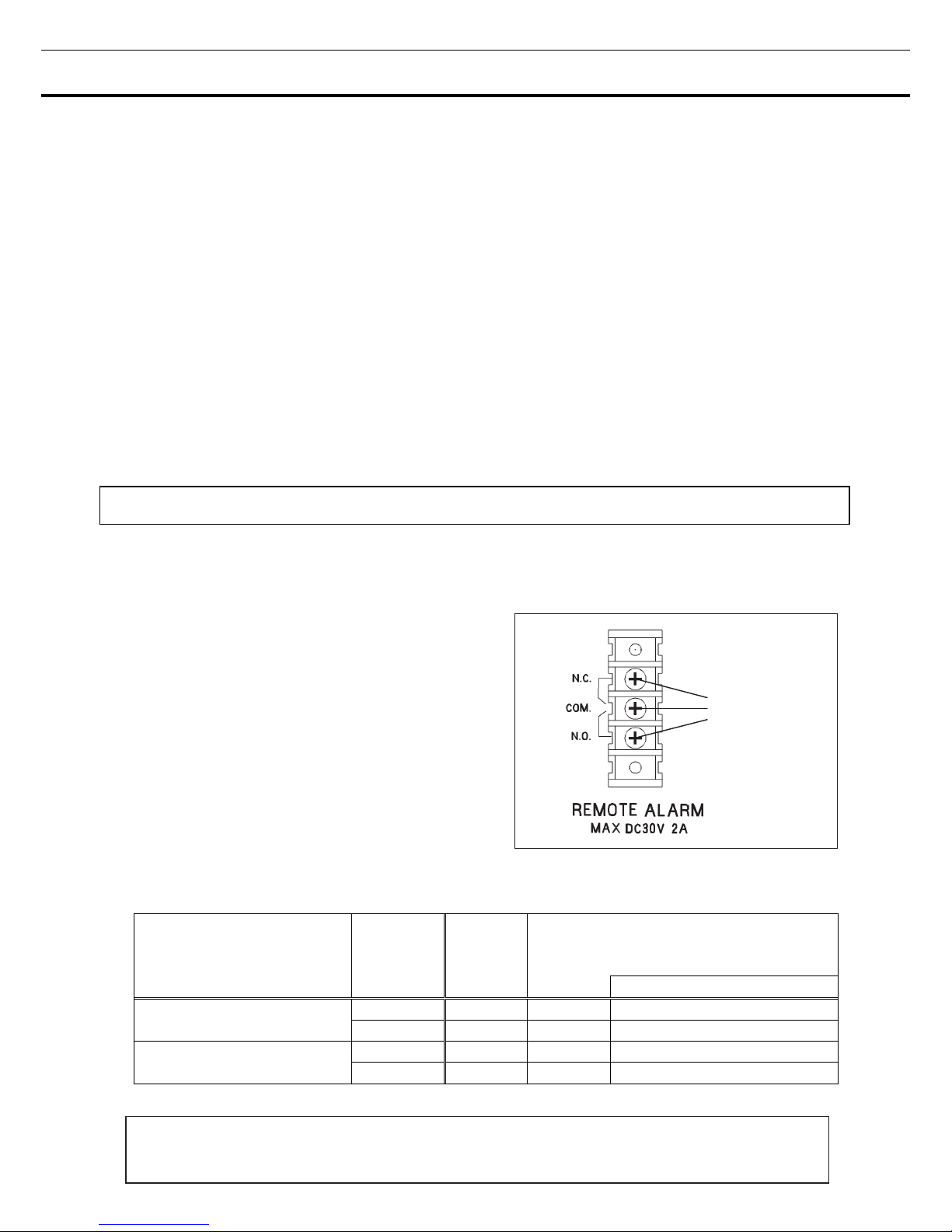
Remote alarm terminal
The alarm of this product can be informed at a remote location from this product by connecting the external
alarm unit to the remote alarm terminals. For the type and behavior of remote alarm output, refer to page
83 to 85.
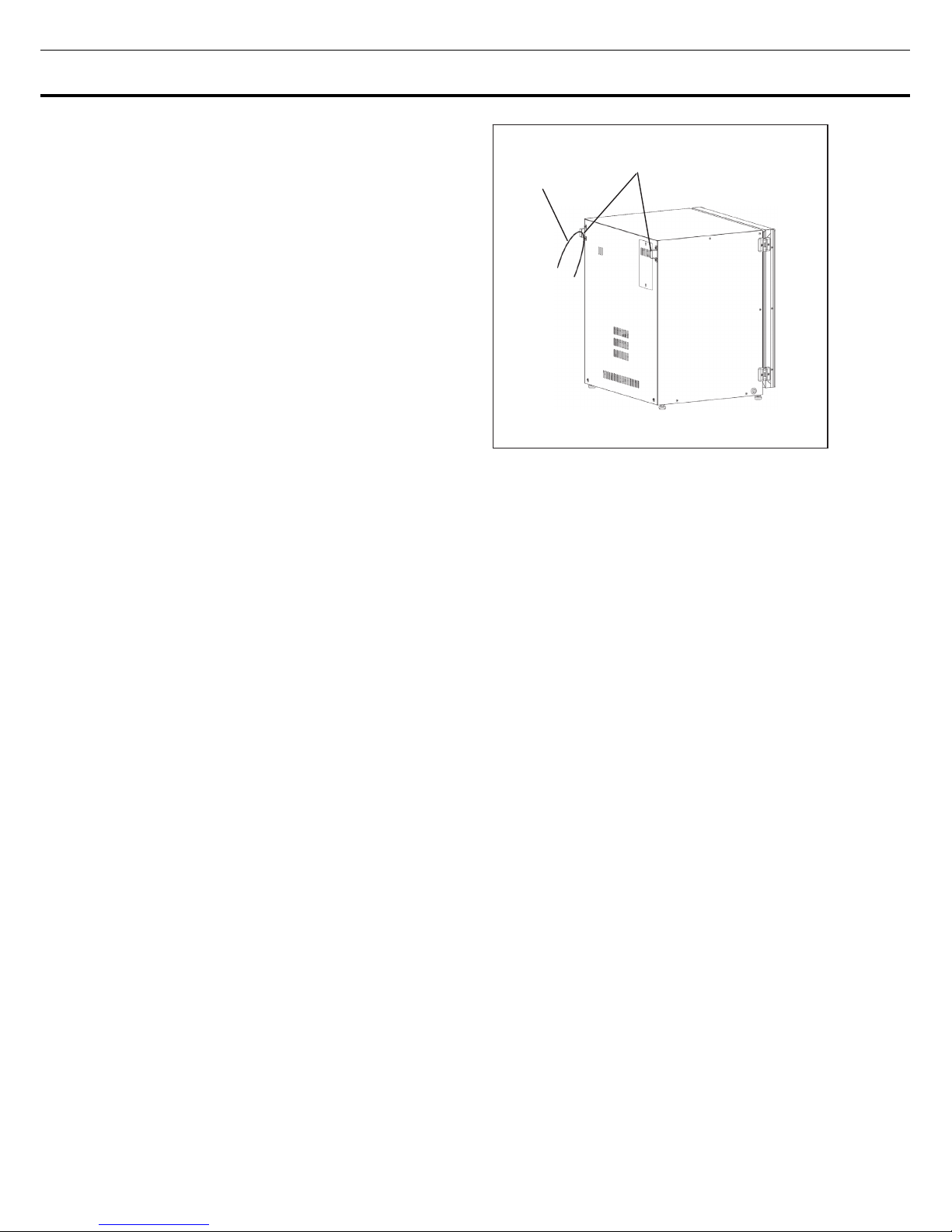
The terminal of the remote alarm is installed at the
rear upper right of the unit (See the figure on the
point). The alarm is outputted from this terminal.
Contact capacity is DC 30 V, 2 A.
When Buzzer key is pressed, the behavior of the
remote alarm is showed in Table.1.
Note:
• In the door alarm, the remote alarm does not work.
Refer to page 83 to 85.
• For wiring of a remote alarm, contact qualified
service personnel.
Table 1 The behavior of the remote alarm when pressing the Buzzer key
Remote Alarm setting
(Refer to page 38~40)
Connecting
terminal
Normal
condition
Abnormal condition
(Including in the cases of power outage and
of where the power plug is pulled out.)
When pressing the buzzer key
ON:
Non-interlock with Buzzer key
COM.-N.C. Close Open Open (Maintain in abnormality)*
COM.-N.O. Open Close Close (Maintain in abnormality)*
OFF:
Interlock with Buzzer key
COM.-N.C. Close Open Close (Return to normal)
COM.-N.O. Open Close Open (Return to normal)
*In case of Err01 (CO2 gas cylinder empty), Err11, 12(CO2 sensor error), the condition returns to normal.
Remote alarm
terminal
Use a twisted sealed wire for the connection.
Type: UL 2343, UL 2448, UL 2464, UL 2552, UL2623.
Length:30 m max.
15
INSTALLATION
Installation site
For correct operation of the incubator, install it in a location with the following conditions.
WARNING
When using CO
2
gas for control, make sure that there is an adequate ventilation. Using CO2 gas in a
small room without adequate ventilation may cause gas poisoning or oxygen deprivation. In addition, when
opening the incubator doors, do not directly inhale the air in the chamber.
Si l’appareil est utilisé dans un evdroit restreint, le niveau de la densite CO
2
de l’air peut s’élever et peut
être nocif aux humains. Evitez d’aspirer l’air provenant de l’inérieur de l’appareil quand vous ouverz la
porte.
Normal air environment
Install the incubator in an environment with normal air.
Do not expose to direct sunlight
Do not install the incubator in a location where it will be exposed to direct sunlight. If the incubator is
operated in direct sunlight, performance will be adversely affected.
Separate from heat sources
Do not install the incubator near significant heat sources, such as heaters, boilers, ovens, or autoclaves.
Heat will adversely affect the performance of the incubator.
Ambient temperature at least 5 C lower than set temperature
The control temperature of the incubator is at least 5 C higher than the ambient temperature. For example,
if the chamber is controlled at 37 C, the ambient temperature must be 32 C or less. Do not allow the
ambient temperature to become too high.
Strong and level floor
Select a site with a strong and level floor. If the floor is uneven or the installation is not level, the incubator
will be unstable and this may cause accident or injury. To avoid vibration and noise, always make sure that
the installation is stable. An unstable surface may result in vibration or noise.
WARNING
Install the incubator at a location that can support the weight. If the floor is not strong enough or if the
installation is insufficient, the incubator may fall over and cause injury.
Always make sure that the floor is strong, even, and level, and that the incubator will not tip over.
An insufficient installation may result in injury due to water leakage or the incubator falling over.
Separate from vibration products
Do not install the incubator near vibration products. Vibration may cause culture failure.
16
INSTALLATION
Low humidity
Select a site with a relative humidity of 80 %R.H. or lower. Using the incubator in high humidity may result
in current leakage or electric shock.
WARNING
Do not use the incubator outdoors. If the incubator is exposed to rain water, it may result in current
leakage or electric shock.
Never install the incubator in a moist location, such as near a sink or water line, or where it is likely
to be exposed to water. In addition, do not install it near water or steam pipes. Moisture can cause the
insulation to deteriorate, which may result in current leakage or electric shock.
No inflammable or corrosive gas
Never install the incubator in a location where it will be exposed to inflammable or corrosive gas. Doing so
may result in explosion or fire. In addition, insulation may deteriorate due to corrosion of protective casing,
resulting in current leakage or electric shock.
No falling objects
Do not install the incubator in a location where there is the possibility of objects falling from above. Doing
so may result in damage or accident.
17
Installation
1. Remove the packing tape and clean up.
Remove all the tapes that are securing the doors and the inner attachments. Open the doors for ventilation.
If the outer panels are dirty, wet a cloth with a diluted neutral detergent and wipe them. (Undiluted
detergent can damage the plastic components. For the dilution, refer to the instruction of the detergent.)
Wipe off the residual detergent with a wet cloth and then wipe off any moisture.
Note: Remove the cable tie banding the power supply cord. Prolonged banding may cause the corrosion
of the cord coating.
WARNING
Do not leave the plastic wrapping bags within reach of children. If the bag is placed over a child’s
head, it can block the mouth and nose and cause suffocation.
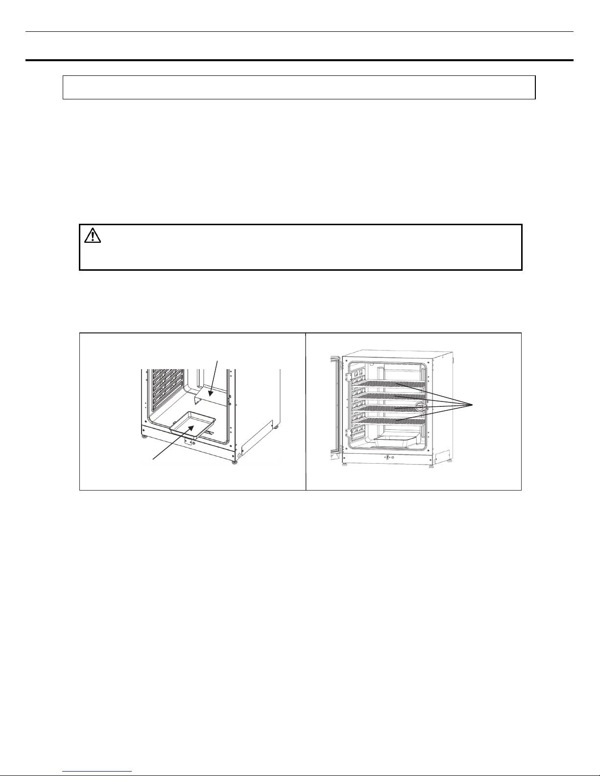
2. Set the humidifying pan and humidifying pan cover (Fig. 1).
3. Set 4 trays (Fig. 2).
Fig. 1
Fig. 2
4 Trays
Humidifying pan
Humidifying pan cover
18
INSTALLATION
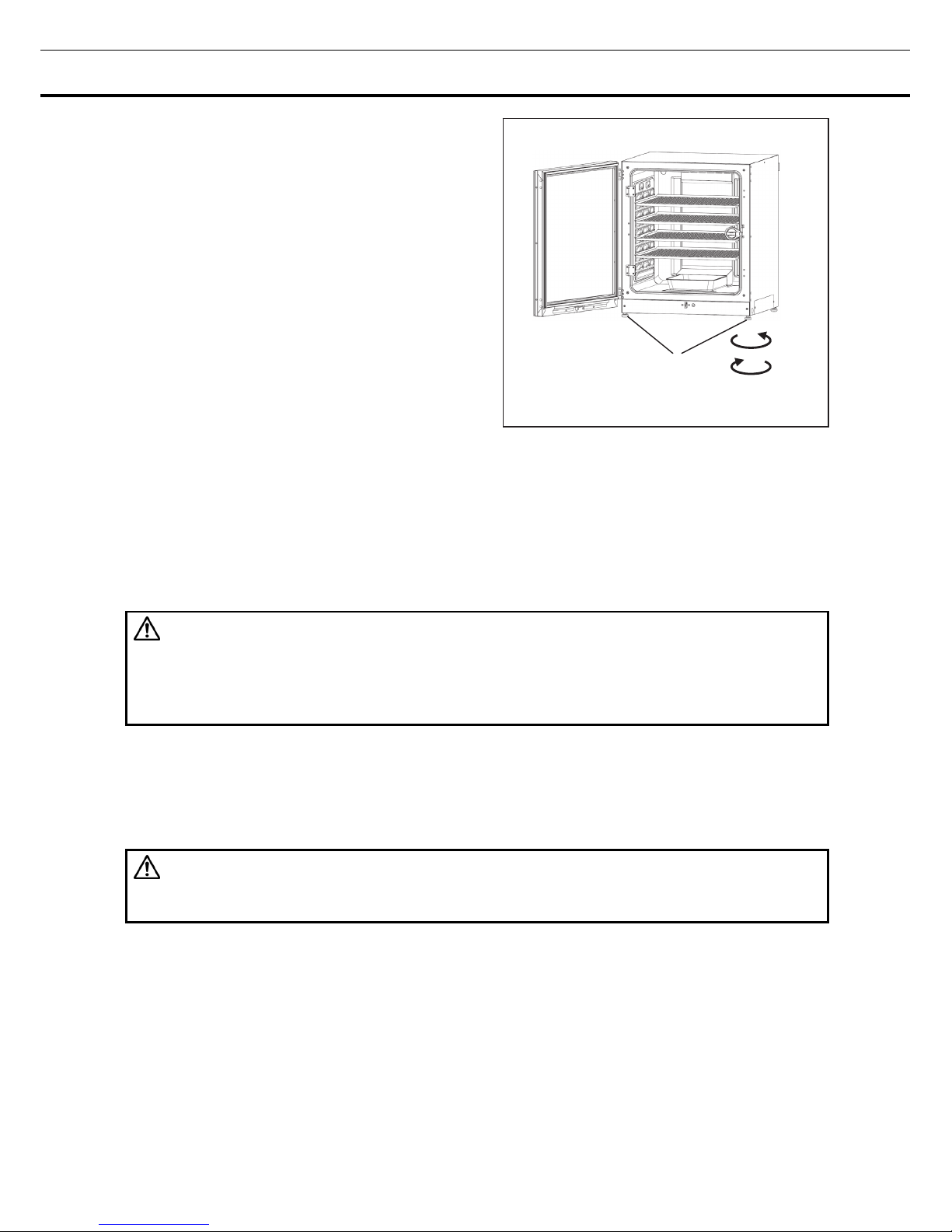
4. Adjust the leveling feet.
Adjust the leveling feet by turning them
counterclockwise to level the incubator (Fig. 3).
Note: Incubating on a leaning tray may have a bad
influence on the cultivation.
5. Ground the incubator.
Ground the incubator during installation to prevent electric shock in case the insulation is not sufficient. If
there is no ground wire at the location, consult with qualified service personnel.
When a ground must be installed
If a grounded 3-pole outlet is not available, then a ground must be installed. Consult with qualified service
personnel.
WARNING
To prevent electric shock, always ground the incubator. If grounding is not possible, then have a ground
installed by qualified personnel. If the incubator is not grounded, it may result in electric shock.
Never connect the ground wire to a gas pipe, water pipe, lightning rod, or telephone ground wire.
Doing so may cause electric shock.
Installing a ground fault circuit breaker
If using the incubator in the location with moisture or humidity cannot be avoided, then it is recommended
that a ground fault circuit breaker be installed in the power supply circuit (i.e., the power supply at the
incubator). Have the circuit breaker installed by qualified service personnel.
CAUTION
Do not climb on the incubator or place objects on top of it. Doing so may damage it or cause it to fall
over, resulting in injury.
Fig. 3
Leveling feet
Shrink
Strec h
19
In case of double stack
For stacking the incubators surely, refer to the
procedure included with the optional double
stacking bracket MCO-170PS or the stacking plate
MCO-230SB.
Note: Two hooks are attached to the rear of the
upper incubator. When stacking incubators, fix the
upper incubator to the wall with these hooks and
wire or chain (Fig. 4).
Note: When stacking the incubators on our CO
2
incubator or O2/CO2 incubator other than this
product, use the stacking plate MCO-230SB. Refer
to table 11 on page 96.
When the incubator is not in use
Empty the water from the humidifying pan and remove moisture from the chamber. Make sure that the
chamber is completely dry before closing the doors. Failure to do so may result in damage.
Before moving the incubator
Before moving the incubator, empty the water from the humidifying pan, disconnect the power supply plug
from the outlet, and make sure that the cord will not be damaged. Failure to do so may result in electric
shock or fire.
Fig. 4
Hooks
Wire
20
INSTALLATION
Connecting CO2 gas cylinder
WARNING
When connecting a gas cylinder to the incubator, confirm the gas type. Confirm that the connections
are secure and that no gas will leak. Be sure to use the specified pressure. Using an incorrect gas or
pressure may result in explosion or fire, or in gas poisoning or oxygen deprivation due to qas leak.
Install the incubator in a location with adequate ventilation. If adequate ventilation cannot be provided,
then install an alarm system using CO
2
and O2 densitometers.
1. Get a CO
2
gas cylinder ready and install an optional gas regulator MCO-100L.
Note:
・Use a liquefied CO
2
gas cylinder (at least 99.5 % pure). The siphon (dip tube) type cannot be used.
・When MCO-100L is not available, install a gas regulator rated at 25 MPa(G) (250 kgf/cm
2
(G), 3600
psi(G)) for the primary side, and 0.2 MPa(G) (2 kgf/cm
2
(G), 30 psi(G)) for the secondary side.
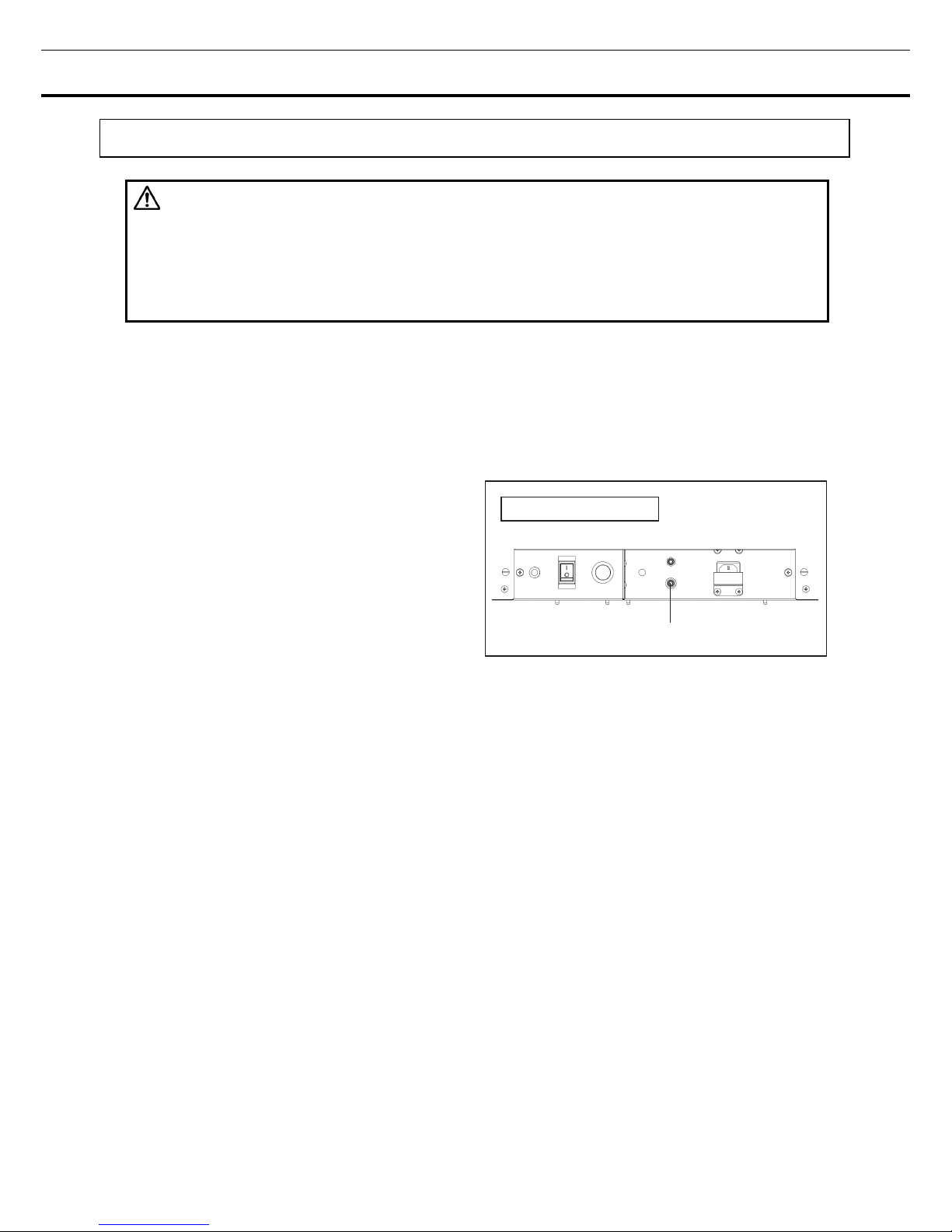
2. Using a gas tube that is provided, connect the
connecting port A for CO
2
gas pipe and the gas
regulator of the CO
2
gas cylinder.
For details on installing the optional automatic CO
2
cylinder changeover kit (MCO-21GC), refer to page
75~77.
Note:
・By using 2 tube bands that is provided, connect the gas tube tightly to prevent it from coming off.
・Make sure that the gas tube is not folded.
・If the CO
2
gas is supplied to multiple CO2 incubators from a single gas cylinder, a CO2 solid will be formed
in the gas regulator. The gas regulator safety valve will operate, and there may an explosive sound.
3. After connecting the gas tube, make sure that no gas is leaking (ex. by using a gas leak detection
spray).
4. Set the CO
2
gas on the secondary side to 0.03 MPa(G) (0.3 kgf/cm2(G), 4.4 psi(G)) for gas injection.
Note: As the pressure increases, the CO
2
gas density control range will increase. Excessive pressure may
cause gas supply lines inside the incubator to come loose, which may result in gas poisoning or oxygen
deprivation due to gas leak. If gas lines come loose, the incubator must be repaired.
5. When there is no CO
2
gas left and the CO2 gas empty alarm is activated, replace the empty gas cylinder
to a new one.
Note: When an optional gas auto changer MCO-21GC is installed, it switches the empty CO
2
gas supply
line to the other automatically. Refer to page 75~77.
Note: The gas lines connected to the incubator will degrade over time. If any deterioration or abnormalities
are found during inspection, replace the lines immediately.
Connecting port A for CO2 gas pipe
Lower right side
21
BEFORE COMMENCING OPERATION
Initial cleaning method
Before using the incubator for the first time, clean dirt (tape residue, smear, etc.) from the
chamber and the inner attachments thoroughly. To keep the chamber clean is essential to
get the proper performance out of the incubator. Use the following steps to clean the
incubator properly.
1. Remove the inner attachments, referring to “Removing inner attachments” on page 22.
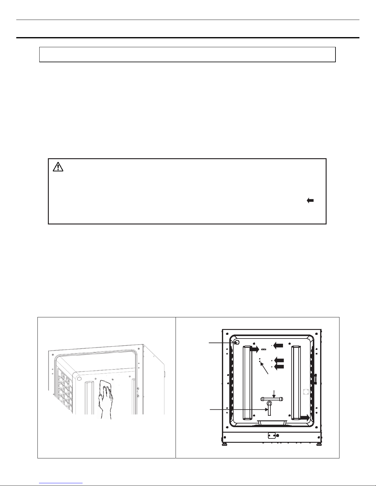
2. Clean the removed inner attachments, the chamber inside walls and the inner door gaskets with a cloth
or sponge soaked in neutral detergent, diluted by 5 % or less. (Undiluted detergent can damage the plastic
components. For the dilution, refer to the instruction of the detergent.) (Fig. 1)
CAUTION
Do not use detergents or antiseptic solutions with acid, alkali, or chlorine. Doing so may cause
discoloration, corrosion, or rusting.
Be careful to keep the diluted detergent or water out of the temperature sensor, the CO
2
gas injection port,
the inner sample air access port, the fan motor shaft bearing, and the inner sample air outlet (Fig.2 ).
Also, do not wash the temperature sensor and the UV lamp using detergent. Doing so may cause failure.
(Fig. 2)
3. Soak a gauze or unwoven cloth in distilled water and wring it tightly, and then wipe off the residual
detergent thoroughly.
4. Wash the silicon caps (2 pcs) for the access port and the fan using the above mentioned detergent and
rinse them with distilled water, and then autoclave them for sterilization (121
o
C, 20 minutes).
5. Wipe up the inside walls and the inner attachments like trays thoroughly with a cloth or unwoven cloth
soaked in alcohol for disinfection. Be careful not to leave any residue alcohol.
6. Reinstall the inner attachments correctly and securely, referring to “Installing inner attachments” on page
24.
Fig. 1 Fig. 2
Silicon
cap
Temp. sensor
(UV lamp)
Humidity
control bar
22
BEFORE COMMENCING OPERATION
Removing inner attachments
CAUTION
Wear rubber gloves when performing maintenance on the chamber. Failure to wear gloves may result
in cuts or abrasions from sharp edges or corners.
Always replace the inner attachments removed for the cleaning to keep the intended performance.
Be careful not to damage the UV lamp in the duct (MCO-230AICUVH/230AICUV or when an optional UV
system set MCO-170UVS is installed).
1. Turn OFF the power to the incubator.
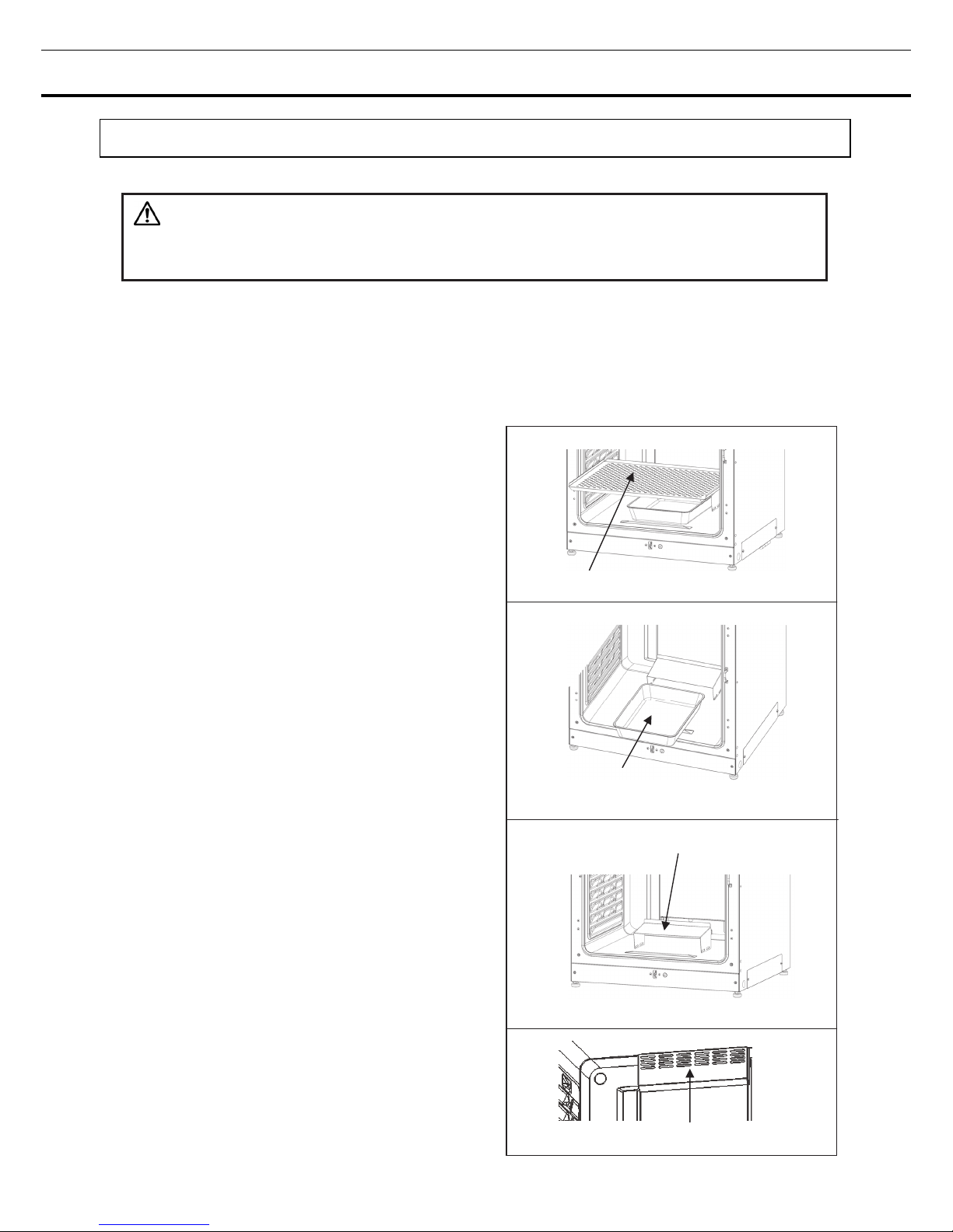
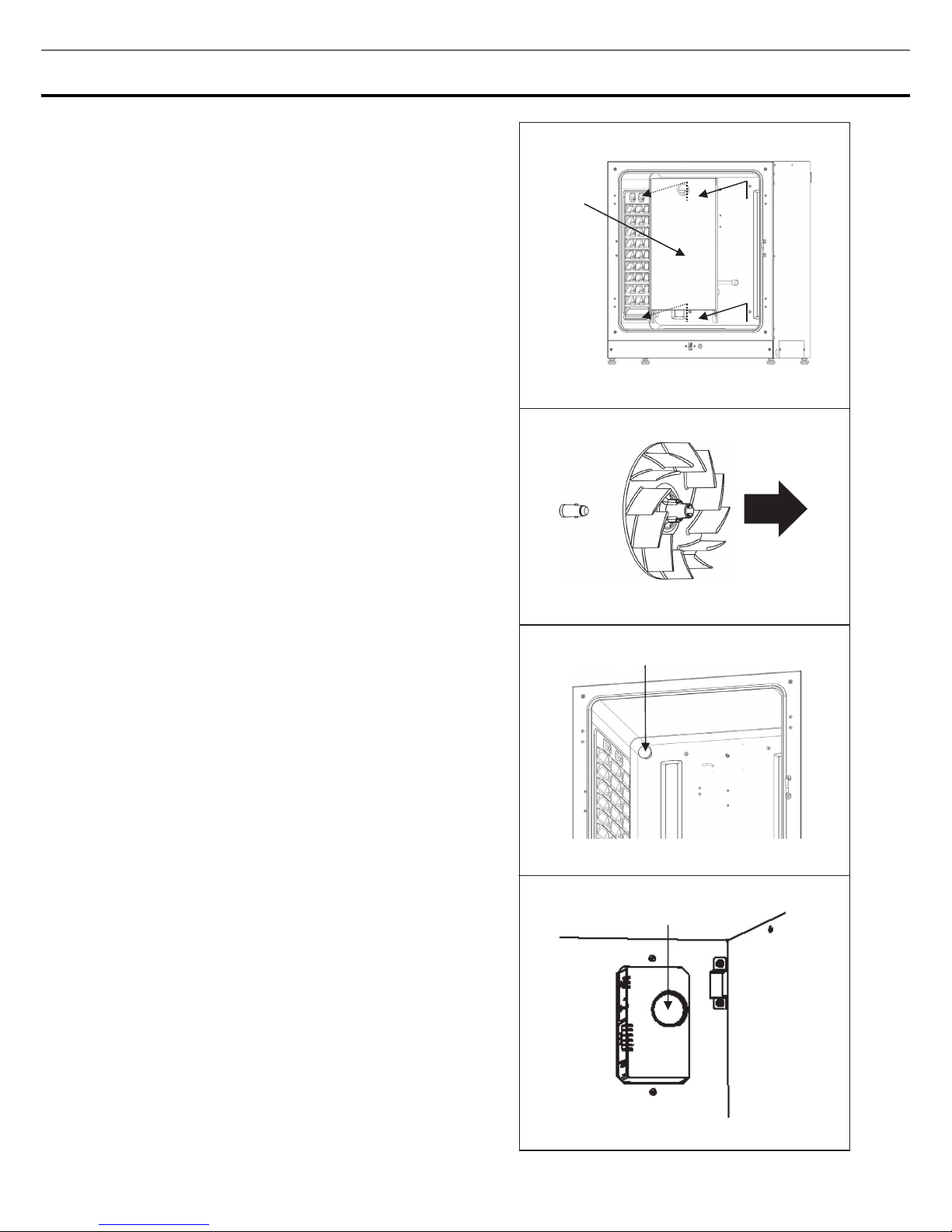
2. Open the outer and inner doors and pull out all the
trays (Fig. 1).
3. Pull out the humidifying pan (Fig. 2).
4. Pull out the humidifying pan cover (Fig. 3).
5. Pull out the fan cover (Fig. 4).
Humidifying pan cover
Fan cover
Fig. 1
Fig. 2
Fig. 3
Fig. 4
Humidifying pan
Tray
23
6. Lift the duct and remove it from the pins on the rear
side (Fig. 5).
7. Pull out the fan (Fig. 6).
8. Remove the silicon caps of each access port from
interior (Fig. 7) and exterior (Fig. 8).
Duct
Silicon cap
Fig. 5
Fig. 6
Fig. 7
Fig. 8
Silicon cap
24
BEFORE COMMENCING OPERATION
Installing inner attachments
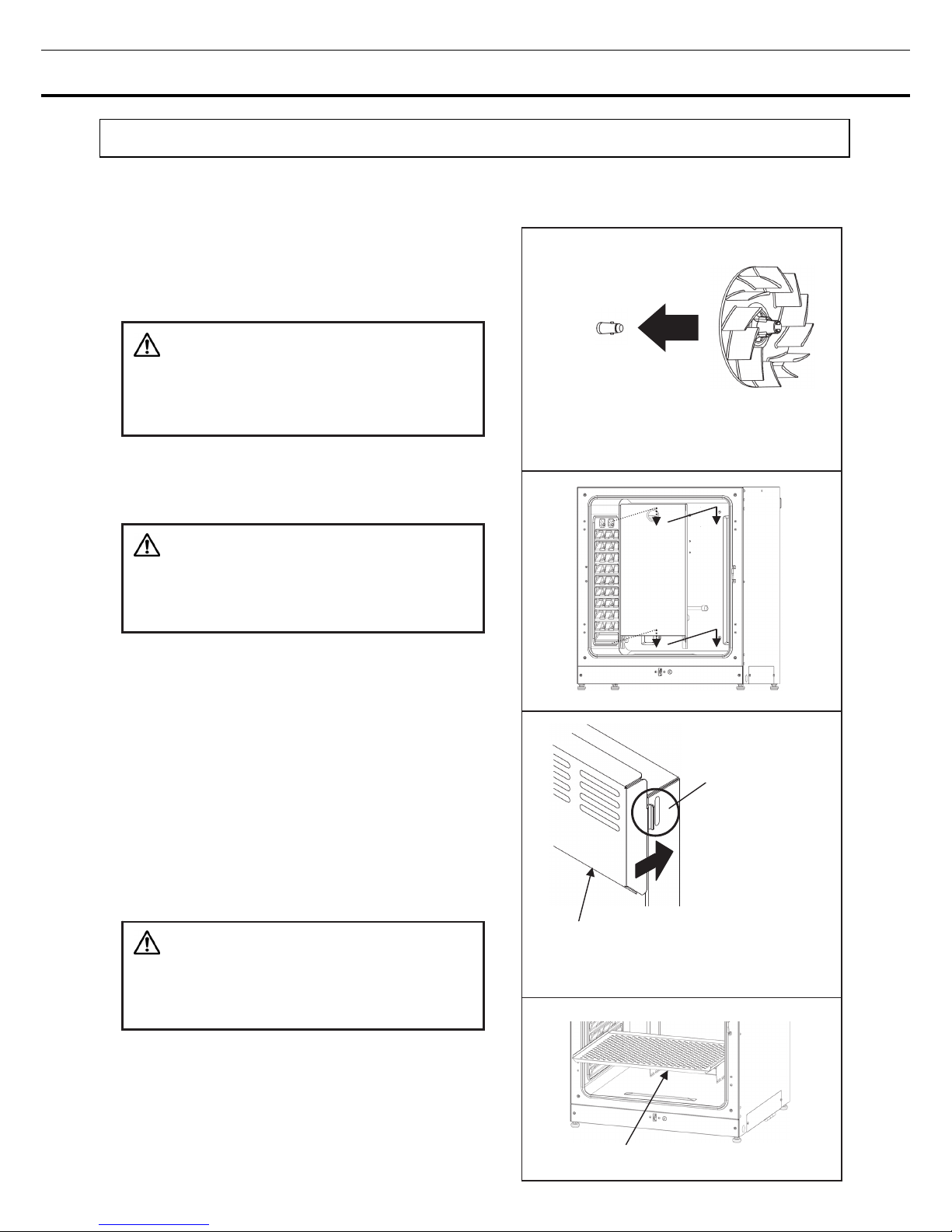
To re-install all the attachments, perform the procedure in reverse order from step 8 on page 23.
Note: When installing the fan, insert it to the motor
shaft securely. Lightly turn and pull the fan
manually to make sure that it does not touch the
rear panel and is installed securely (Fig. 1).
CAUTION
If the fan is not inserted deep enough, the intended
velocity performance cannot be achieved, and it may
cause culture failure or insufficient decontamination.
Note: To install the duct, confirm 4 pins are
securely installed in the 4 holes of the duct (Fig. 2).
CAUTION
If the duct is fixed insecurely, the intended velocity
performance cannot be achieved, which may cause
culture failure or insufficient decontamination.
Note: When installing the fan cover, position the
long hole of duct with the projection of fan cover
and insert directly (Fig. 3). Same applies for the
humidifying pan cover.
The fan cover may lean by strongly pushing the
head of it in the back. Make sure that there is no
space in the lower fan cover after installing
because the leaning fan cover may have a bad
influence on the camber temperature distribution.
CAUTION
If the fan cover is fixed insecurely, the intended
velocity performance cannot be achieved, which may
cause culture failure.
Note: Set the tray with only the front edge bent
down (Fig. 4).
①Position the center hole of the fan with the
projection of the motor shaft.
And insert it deeply.
Fig. 1
Fig. 2
Bent down
Fig. 4
Fig. 3
①Position
and insert.
②Confirm the
direction of fixing
position as shown.
③Make sure that there is no space in
the lower of fan cover.
②Lightly turn the fan manually
to make sure that it does not touch the rear panel.
③Lightly pull the fan manually to make sure that
it is installed.
25
Filling humidifying pan
Use the following procedure to fill the humidifying pan with water or to replace water in the humidifying
pan.
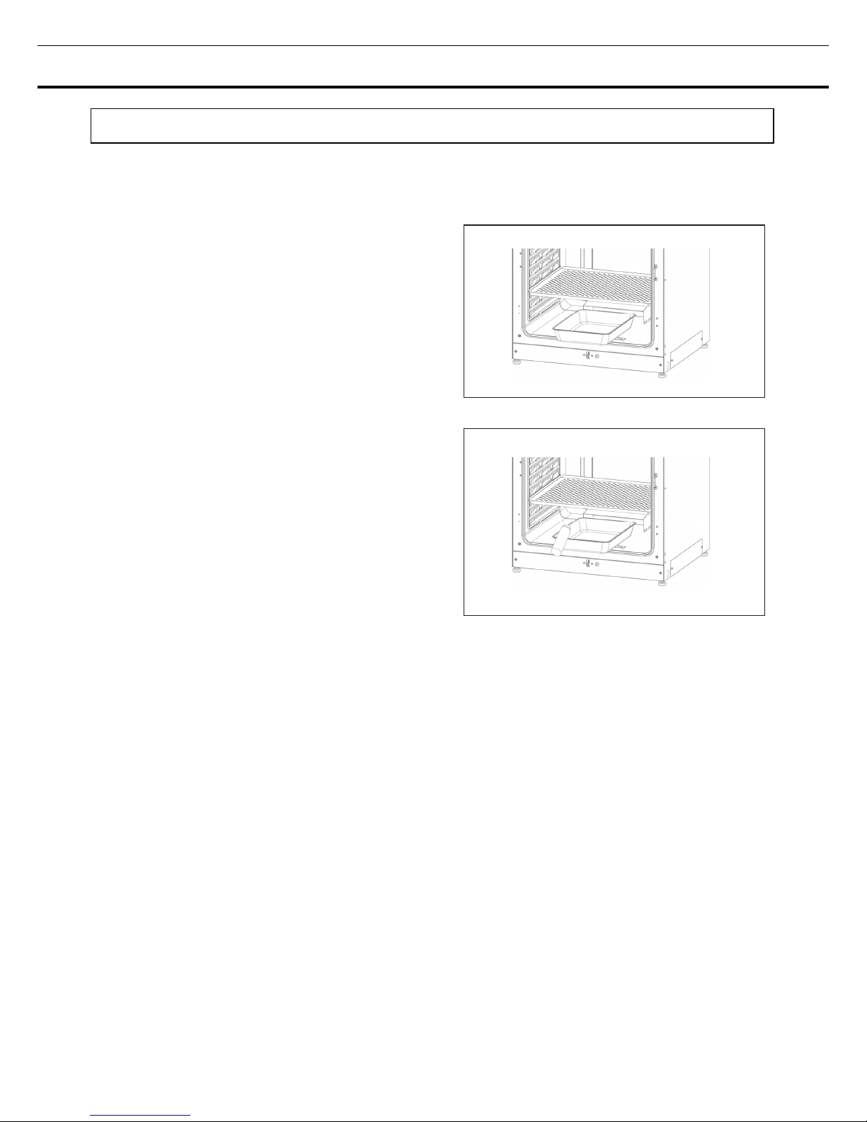
1. Pull out the humidifying pan toward you. (Fig. 1)
2. Dispose of the remaining water in the humidifying
pan and clean the humidifying pan with a diluted
detergent. Then rinse it thoroughly with distilled
water and wipe it with alcohol for disinfection.
3. Wipe all moisture from the bottom of the chamber.
4. Return the humidifying pan to the chamber and
pour sterile distilled water (approx. 1.5 L, preheated
to 37 C). (Fig. 2)
Note:
・Operation with no humidifying water may increase the chamber temperature than the set temperature
temporarily.
・Preheat the water to 37 C to be poured into the humidifying pan. Adding low-temperature water will lower
the temperature and humidity in the chamber.
・Install the humidifying pan in a longitudinal direction as its shorter side is placed in the back.
・Refill the humidifying pan with water early when the volume of water is decreased.
・Mixing any reagent in the humidifying water may have a bad influence on the cultivation. Especially when
using the UV lamp, do not use any reagent. Because the UV light may deteriorate the reagent mixed with
the humidifying water.
5. Set the humidifying pan with the inner side flush against the back, and close the inner door and the outer
door.
Note: Set the humidifying pan with the inner side flush against the back. The humidity control bar in the
duct keeps at low temperatures and inner moisture is recondensed. Slide the humidifying pan down right
under the humidity control bar, otherwise the recondensed water drops will directly fall to the chamber
bottom and will pool in the chamber bottom.
When the pooled water evaporates, it may leave a white mark on the chamber bottom. This is not a
malfunction. Wipe it off with alcohol-soaked gauze or unwoven cloth. When the mark cannot be removed,
scrub the mark off with using a cream cleanser.
Fig. 1
Fig. 2

26
FOR BETTER CULTIVATION
Precautions for cultures
Leave space between culture containers.
Always leave space for ventilation between culture containers (Petri dishes, flasks, etc.). Inadequate
spacing may result in uneven temperature distribution and CO
2
gas density.
Do not place harmful materials in the chamber.
Never place samples that release acidic, alkali, or corrosive gas in the chamber. Doing so may cause
damage resulting from discoloration or corrosion.
Close the inner door.
Always close the inner door before closing the outer door. Failure to close the inner door will adversely
affect performance even if the outer door is closed.
Open and close the doors gently.
Always open and close the doors gently. Closing the doors forcefully may cause spillage of the culture
medium, incomplete closing, or damage to the gasket. Before opening the inner door, check through the
glass to confirm that the UV lamp is OFF (if the MCO-230AICUVH/230AICUV or the optional
MCO-170UVS is installed).
Be careful when closing the outer door.
Use the handle when closing the outer door. Holding the door in other places may cause injury by getting
fingers caught in the door. Do not lean on the outer door. Doing so may result in injury from the outer door
coming loose or the incubator falling over, or it may cause current leakage or electric shock.
Be careful of the inside of the outer door.
The inside of the outer door may become hot.
Avoid using excessive force on the inner door.
Do not put your hand on the glass, poke it with sharp objects, or apply strong force. Doing so may result in
injury from breaking the glass.
Check the cause of any alarm buzzer.
If an alarm buzzer sounds while the incubator is in use, immediately check the cause of the alarm. For
details on what may cause an alarm buzzer to sound, refer to page 83~85.
Vibration of a shaker.
When stacking incubators and operating the shaker for CO
2
incubator MIR-S100C in the chamber of the
CO
2
incubator, it may have a bad influence on the other.

27
Preventing contamination
To prevent contamination of the chamber, select a suitable installation site.
Avoid locations with high temperatures or humidity.
Avoid locations with high temperatures or humidity, because of a greater presence of microorganisms in
the air.
Avoid locations with passers-by or drafts.
Avoid locations near doors, air conditioners, fans, etc., where passers-by or drafts can facilitate the entry of
microorganisms into the chamber.
If possible, use a cleanroom.
To achieve a better culture, it is recommended that a cleanroom be used if one is available.
Use clean containers.
The greatest cause of contamination is dirty containers for cultures. Be careful not to get containers or
trays dirty when taking them in and out.
Keep the chamber clean.
Wipe off any fingerprints. If water spills from the humidifying pan, or if the doors are left open for a long
time, condensation may form on the inside of the doors. If that occurs, wipe off the condensation with a dry
sterile gauze. In particular, clean and disinfect the chamber if the culture medium is spilled. For details,
refer to “ROUTINE MAINTENANCE” on page 82.
Use sterile distilled water in the humidifying pan.
Always use sterile distilled water in the humidifying pan. Do not use ultrapure water, because it may cause
red rust-like particles in the humidifying pan. Clean the humidifying pan once a month. In some cases, an
antibacterial ingredient may precipitate in the humidifying water. This is not a malfunction.
Keep the incubator out of direct airflows from air conditioners or fans.
Cool airflow from an air conditioner may cause condensation and lead to possible contamination.
28
CORRECT OPERATION
Use the following procedure to start trial operation or actual operation of the incubator.
1. Install the incubator correctly, referring to “INSTALLATION” on page 16 to 20.
2. Remove the packing materials from the chamber and inner attachments. Clean and disinfect the
chamber and all the inner attachments, referring to “ROUTINE MAINTENANCE” on page 82.
3. Add approximately 1.5 L of sterile distilled water to the humidifying pan (Refer to page 25).
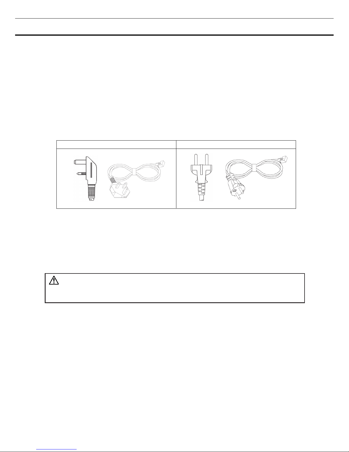
4. Connect the removal power supply cord that is provided, to the port on the lower rear side.
Note: 2 removal power supply cords are provided.
For UK For EU countries other than UK
5. Connect the removable power supply cord to the outlet.
6. Turn ON the power switch on the lower right side of the incubator.
7. (MCO-230AICUVH/230AICUV or when an optional UV system set MCO-170UVS is installed.) Set the
frequency of a power supply on the LCD touch panel (Refer to page 58~59).
WARNING
Always use the removal power supply cord that is provided. Other power supply cord may cause
electric shock or fire.
The provided removal power supply cord is only for this product.
Never use it for any other products.
When the incubator is not in use
Empty the water out of the humidifying pan and remove moisture from the chamber. Make sure that the
chamber is completely dry before closing the doors. Failure to do so may result in damage.
Before moving the incubator
Before moving the incubator, empty the water out of the humidifying pan, disconnect the power supply plug
from the outlet, and make sure that the cord will not be damaged. Failure to do so may result in electric
shock or fire.
 Loading...