

Page 1
SPECIFICA TIONS
MC-E761
Power source AC230V
AC230-240V Depending on version
50Hz
Input power (max.) 1500W
Vacuum 29 kPa
Power cord length 5 m
Radio of operation 7.8 m
Net weight 6.1 kg
Dimensions (LxWxH) mm 410x282x255
Attachments:
Floor nozzle
•
Extension tube
•
Crevice nozzle
•
Specifications are subject to change without notice for further improvement.
MODEL MC-E761
Ref.: Z32T4000
Matsushita Electric España, S.A.
VACUUM CLEANER DIVISION
Zona Industrial del Polígono de CELRÀ
17460 CELRÀ (Girona) SPAIN
Vacuum Cleaner
Page 2

2
TABLE OF CONTENTS PAGE
SPECIFICATIONS ............................................................................... 1
SCHEMATIC DIAGRAM ....................................................................... 3
PICTORIALWIRING DIAGRAM
................................................................. 3
EXPLODED VIEW
.............................................................................. 4
SPARE PARTS LIST
........................................................................... 7
REPLACEMENT OF MAIN PARTS
........................................................... 9
TROUBLE SHOOTING GUIDE
............................................................... 17
PACKING INSTRUCTIONS
.................................................................... 18
Page 3
3
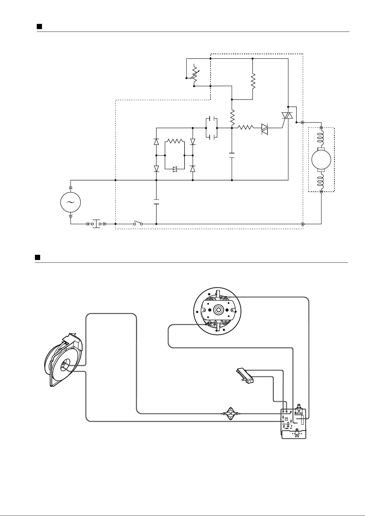
PICTORIALWIRING DIAGRAM
MC-E761
SCHEMATIC DIAGRAM
MC-E761
Black
Black
Yellow
Black
POWER
SUPPLY
AC 230 V
50 Hz
ON/OFF
SWITCH
C5
D4
D5
L1 AC1
D2
C6
VR22
VR21
R6
VR2
R1
NL2
R3
CN2
T2
T1
G
CN1
DIAC
TRIAC
C4
C2
D3
R4
C3
MOTOR
+
M
Grey
Blue
THERMAL
CUT-OUT
CORD REEL
Black
MOTOR
Yellow
Blue
POTENTIOMETER
Black Black
White
THERMAL
CUT-OUT
Grey
ON/OFF
SWITCH
POWER
CONTROL
CIRCUIT
Page 4
4
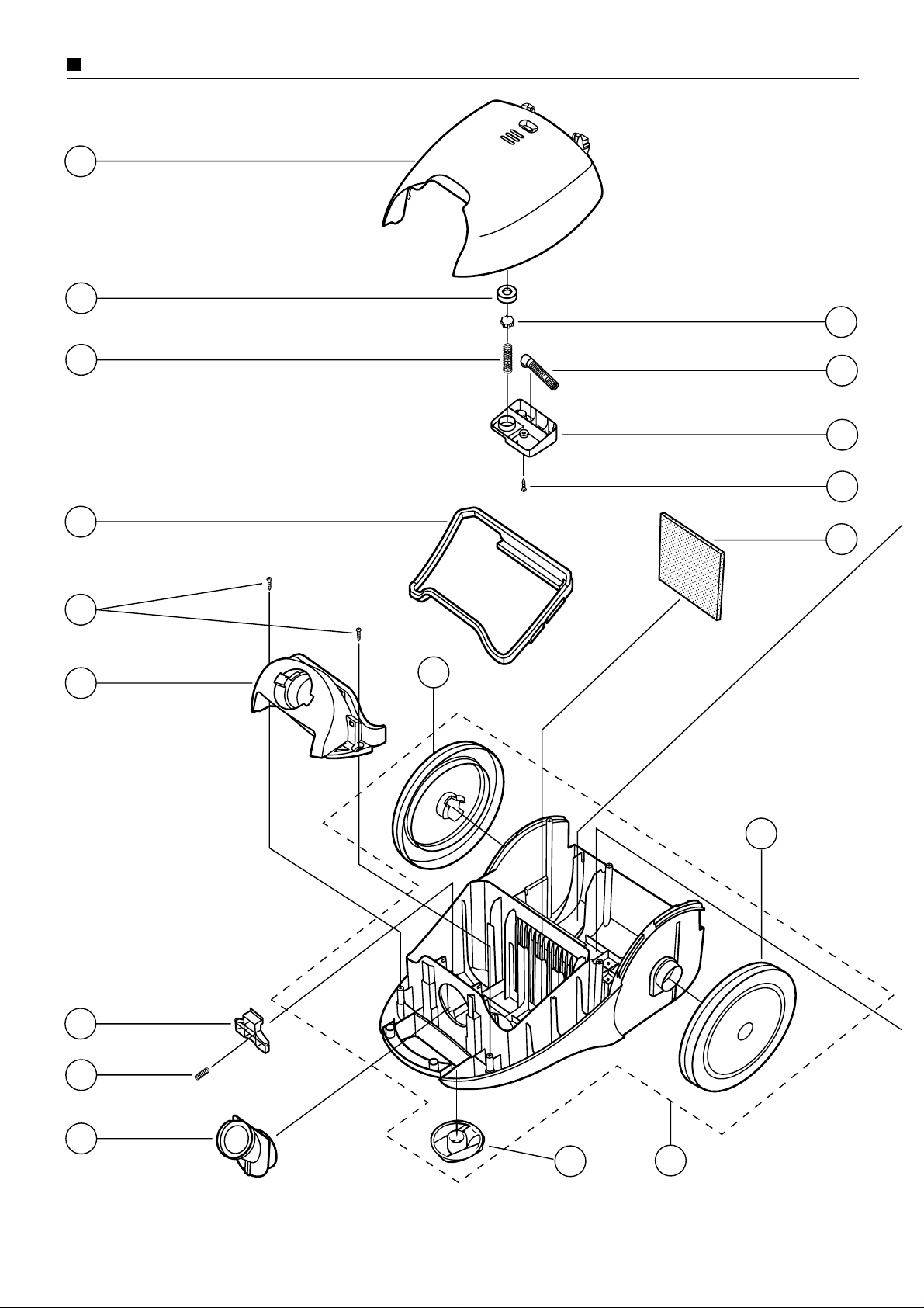
EXPLODED VIEW
15
16
11
12
30
13
14
33
29
32
35
36
31
28
27
29
10
34
Page 5
5
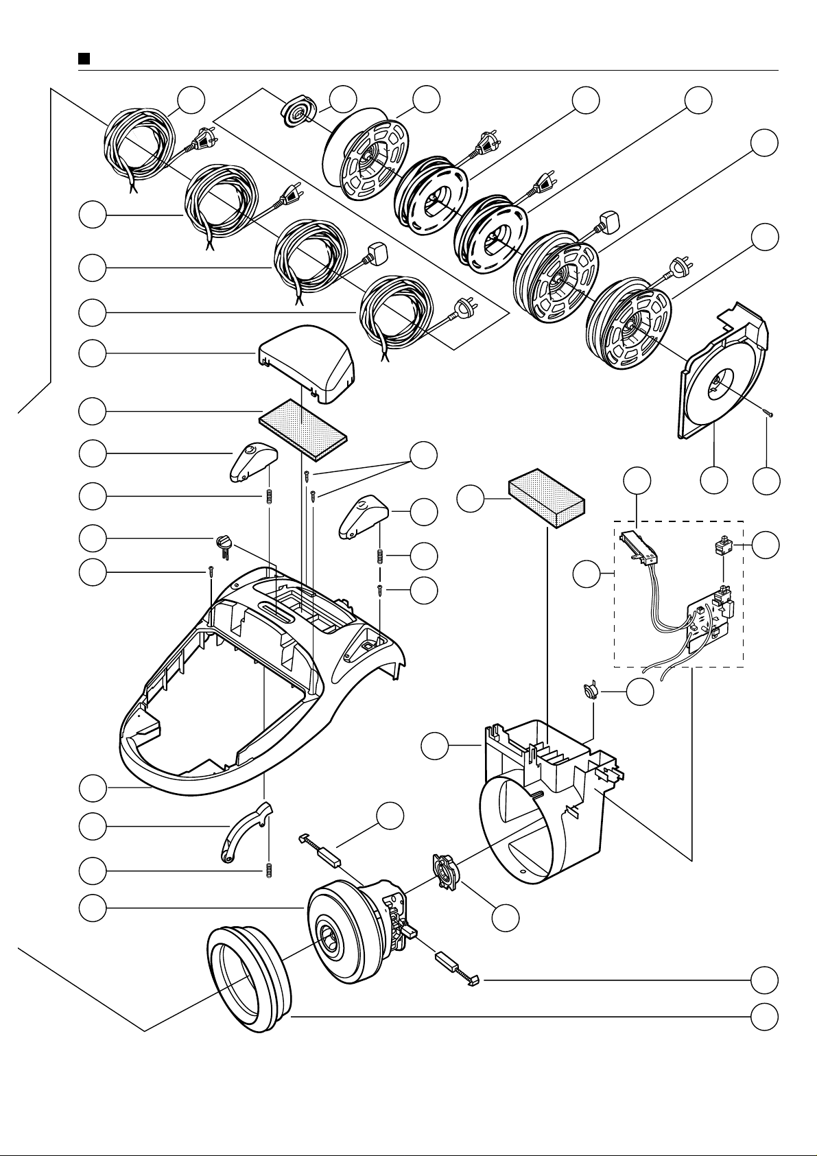
EXPLODED VIEW
58
45
26
25
22
43
24
18
17
41
18
39
38
42
46
44
38
23
24
19
18
50
51
54
53
55
49
48
47
57
37
21
20
40
52
56
Page 6
6
EXPLODED VIEW
9
6
4
60
F
o
M
r
M
C
M
M
C
-E
C
-E
o
7
d
-E
S
8
e
7
8
ls
S
8
:
S
e
r
e
ie
rie
e
rie
s
s
s
P
A
TYPE C-20
P
G
E
E
R
NU
B
A
G
M
D
a
Z
i
v
ts
o
is
n
i
a
ush
n
I
n
d
d
e
u
i
A
s
ta
s
t
r
p
i
a
E
i
r
l
a
d
d
lec
e
o
l
r
P
a
tric
s
o
l
g
o
E
n
o
sp
d
e
a
C
ñ
e
l
r
a, S
1
7
.A
4
6
.
0
C
E
L
R
¸
(
G
i
r
o
n
a
)
E
s
p
a
a
3
INE
E
In
s
O
tr
p
M
u
e
c
a
r
c
a
n
io
t
M
u
in
C
n
a
-
g
E
l d
e
7
in
s
8
0
e
d
,
s
i
M
e
t
n
C
r
M
s
u
-
E
t
c
7
a
r
8
ti
u
1
n
o
,
ç
e
M
n
o
jo
C
s
e
-
E
s
7
8
3
59
66
1
61
5
64
2
63
65
8
7
62
Page 7

7
SPARE PARTS LIST
REF. No. DESCRIPTION PART No. Pcs/Set
MC-E761
REMARKS
1 HOSE UNIT AMC8A92T1034 1 • ✓
2 HOSE AMC8A01K0034 1 • ✓
3 HOSE CONNECTING TUBE AMC8A0281034 1 • ✓
4 CURVED TUBE UNIT AMC8A94P1034 1 • ✓
5 HOSE HOLDER AMC8A1125034 2 • ✓
6 CREVICE NOZZLE AMC8A13P1034 1 • ✓
7 EXTENSION WAND (METALLIC) AMC8A12P1000 2 • ✓
8 TELESCOPIC WAND AMC8A85P3100 1 • ✓ Optional
9 FLOOR NOZZLE AMC8A99T4034 1 • ✓
10 DUST COVER AMC8T01T40Z2 1 • ✓
11 DUSTINDICATOR AMC8I99T1000 1 • ✓
12 VALVE AMC8I07A1000 1 • ✓
13 VALVE SPRING AMC8I09T1000 1 • ✓
14 VALVE SUPPORT AMC8I22E1061 1 • ✓
15 INDICATOR COVER AMC8I17T1164 1 • ✓
16 TAPPING SCREW XTN4+18B 1 • ✓
17 UPPER BODY AMC8C01T50Z2 1 • ✓
18 TAPPING SCREW XTN4+18B 4 • ✓
19 POTENTIOMETER BUTTON AMC8E17T1039 1 • ✓
20 BRAKE LEVER UNIT AMC8P96T1000 1 • ✓
21 BRAKE SPRING AMC8F30L1000 1 • ✓
22 SWITCH PEDAL AMC8T14T1039 1 • ✓
23 CORD REEL PEDAL AMC8T13T1039 1 • ✓
24 SPRING AMC8P2201000 2 • ✓
25 CLEAN AIR FILTER AMC8F28T1000 1 • ✓
26 EXHAUST COVER AMC8T07T40Z2 1 • ✓
27 LOWER BODY UNIT AMC8C99T0039 1 • ✓
28 CASTER AMC8R99V10G0 1 • ✓
29 WHEEL AMC8R01T1039 2 • ✓
30 DUST COVER SEAL AMC8T04T1034 1 • ✓
31 SUCTION PACKING AMC8T12T1000 1 • ✓
32 FRONT COVER AMC8T11T10Z2 1 • ✓
33 TAPPING SCREW XTN4+18B 2 • ✓
34 CENTRAL FILTER AMC8F03D1100 1 • ✓
35 PAPER BAG CLAMP AMC8F02E1164 1 • ✓
36 PAPER BAG CLAMP SPRING AMC8F30E1000 1 • ✓
37 MOTOR SDS-1504P 2 AMC81SF04P02 1 • ✓
38 CARBON BRUSH AMC8210C9801 2 • ✓
39 FRONT MOTOR SUPPORT AMC8E08T1000 1 • ✓
40 REAR MOTOR SUPPORT AMC8E09T0000 1 • ✓
41 MOTOR COVER AMC8E10T4000 1 • ✓
42 THERMAL CUT-OUT AMC8E14L1000 1 • ✓
43 POWER CONTROL CIRCUIT AMC8E91T4100 1 • ✓
44 SLIDING POTENTIOMTER AMC8E1693000 1 • ✓
45 ON/OFF SWITCH AMC8E01P1000 1 • ✓
46 REAR SUPPRESOR AMC8T09T4000 1 • ✓
47 CORD REEL UNIT AMC8PZ3P6000 1 • Applied to Australia and N.Zealand
48 CORD REEL UNIT AMC8PZ1P6000 1 • Applied to UK and Ireland
49 CORD REEL UNIT AMC8P88P6000 1 • Applied to Switzerland
Applied for
all countries (✓)
Page 8

8
SPARE PARTS LIST
REF. No. DESCRIPTION PART No. Pcs/Set
MC-E761
REMARKS
50 CORD REEL UNIT AMC8P97P6000 1 •
Applied to East & West European countries,
except the above.
51 CORD REEL AMC8P90P1000 1 • ✓
52 RAIL BASE UNIT AMC8P93L1000 1 • ✓
53 POWER SUPPLYCORD AMC8EZ3L0061 1 • Applied to Australia and N.Zealand
54 POWER SUPPLYCORD AMC8EZ1L0061 1 • Applied to UK and Ireland
55 POWER SUPPLYCORD AMC8E98L0061 1 • Applied to Switzerland
56 POWER SUPPLYCORD AMC8E97L0061 1 •
Applied to East & West European countries,
except the above.
57 CORD REEL SUPPORT UNIT AMC8P91T1000 1 • ✓
58 TAPPING SCREW (CORD REEL) XTN4+16K 1 • ✓
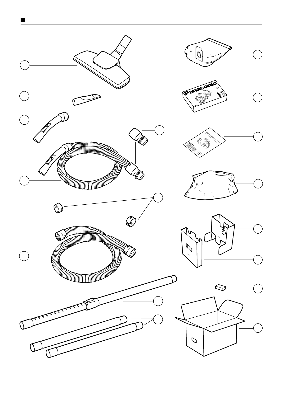
59 DUST PAPER BAG (PACK 5/UNIT) AMC8F96T1000 1 • ✓ Detachable type C-20E
60 CLOTH DUST BAG AMC8F99T1000 - • ✓ Optional
61 SET COVER AMC8Z05P1000 1 • ✓
62 CARTON BOX AMC8Z01T4100 1 • For version with Telescopic wand
CARTON BOX AMC8Z01T4000 1 • For version with Extension wand
63 CUSHION A AMC8Z02T1000 1 • ✓
64 CUSHION B AMC8Z03T1000 1 • For version with Telescopic wand
CUSHION B AMC8Z03T4000 1 • For version with Extension wand
65 CUSHION SUPPLEMENT AMC8Z09J2000 1 • ✓
66 OPERATING INSTRUCTIONS AMC8Z07T1210 1 •
Depend on Spanish, English, Portuguese,
language Italian, Finish and Greek
OPERATING INSTRUCTIONS AMC8Z07T1270 1 •
Depend on German, Dutch, French,
language Swedish, Norwegian and Danish
OPERATING INSTRUCTIONS AMC8Z07T1220 1 •
Depend on
Russian
language
Applied for
all countries (✓)
Page 9

9
REPLACEMENT OF MAIN PARTS
IMPORTANT: Before replacing any part always
DISCONNECT THE CLEANER FROM THE
ELECTRICITY SUPPLY.
• MOTOR / CARBON BRUSHES
(1) Motor
1. To remove the dust cover first pull it out from one side and
then rotate it up wards to take it out. (Fig.1)
2. Remove cord reel and switch pedal prying out as indicated
with a flat-head screwdriver. (Fig. 2)
NOTE: When prying out take care not to damage the body.
Fig. 2
Fig. 1
Dust cover
Cord reel Pedal
Switch
Pedal
Flat-head
screwdriver
Page 10

10
REPLACEMENT OF MAIN PARTS
3. Remove 7 screws from upper body and take out front cover
and upper body. (Fig. 3)
4. Remove black and white lead wires (provided with quickconnect terminal) from the contact spring tabs and take out
cord reel ass’y and motor unit. (Fig. 4)
Fig. 4
Motor unit
Fig. 3
Front cover
Cord reel
Pedal
Switch
Pedal
Upper
body
Lower body
Spring
Spring
Contact
spring
tabs
Cord reel
ass’y
Page 11

11
REMPLACEMENT OF MAIN PARTS
5. Disconnect yellow and black lead wires (provided with
quick-connect terminal) from the power control circuit tabs.
(Fig. 5)
Fig. 5
Remove
(quickconnect
terminals)
Rear filter
Sliding
potentiometer
6. Remove motor cover and rear/front motor support from the
motor. (Fig. 6)
Fig. 6
Front motor
support
Rear motor
support
Motor
Motor cover
Fig. 7
7. Disconnect yellow and black lead wires (provided with
quick-connect terminal) from the carbon brush holder tabs
and replace the motor with a new one. (Fig. 7)
8. Reassemble motor unit in the reverse order.
NOTE: Adjust the position of the rear motor support to the
proper motor cover position.
9. Place the motor unit and cord reel ass’y into the lower
body.
10. Connect the lead wires according to the schematic
diagram and reassemble the remaining parts in the
reverse order.
Yellow
Black
Page 12

12
REPLACEMENT OF MAIN PARTS
Fig. 11
(2) Carbon brushes
NOTE: The two carbon brushes should be replaced at
the same time.
1. Take out motor unit and remove motor cover A and B as
explained previously in paragraph (1) “Motor”, points 1-6.
2. Disconnect yellow and black lead wires (provided with
quick-connect terminals) from the carbon brush holder tabs.
3. Bend the metal end of the carbon brush holder and take out
the carbon brush. (Fig. 8)
4. Cut off the metal end of the carbon brush. (Fig. 9)
Fig. 10
Fig. 9
Fig. 8
Cut metal end
Carbon
brush
Carbon brush
Metal end
holes
5. Insert the new carbon brush into the brush holder and push
the carbon brush until the protruded pins of the brush holder
fix into the holes of the metal end. (Fig. 10)
6. Connect yellow and black lead wires to the carbon brush
holder tabs and reassemble motor unit.
7. Place motor unit and cord reel ass’y into the lower body.
8. Connect the lead wires according to the schematic diagram
and reassemble the remaining parts in the reverse order.
Metal end
• THERMAL CUT-OUT
1. Take out cord reel ass’y and motor unit as explained
previously in paragraph (1) Motor, points 1-4.
2. Take out thermal cut-out from its fastening points and
disconnect lead wires (provided with quick-connect
terminal) from the thermal cut-out tabs. (Fig.11)
3. Replace the thermal cut-out with a new one and connect the
lead wires to the tabs. Then re-install it.
4. Place motor unit and cord reel ass’y into the lower body.
6. Connect the lead wires according to the schematic diagram
and reassemble the remaining parts in the reverse order.
Termal cut-out
Thermal
cut-out
tabs
Page 13

13
REPLACEMENT OF MAIN PARTS
• POWER CONTROL CIRCUIT / ON/OFF SWITCH /
SLIDING POTENTIOMETER
(1) Power Control Circuit
1. Take out cord reel ass’y and motor unit as explained
previously in paragraph (1) “Motor”, points 1-4.
2. Disconnect yellow and black lead wires (provided with
quick-connect terminals) from the power control circuit
tabs. (Fig. 12)
Fig. 12
Remove
(quickconnect
terminals)
Power control circuit
3. Remove power control circuit from its fastening points and
disconnect the lead wires from the power control circuit.
(Fig. 13)
4. Replace power control circuit with a new one and connect
the lead wires according to the schematic diagram.
5. Reinstall power control circuit in its holding points.
6. Place motor unit and cord reel ass’y into the lower body and
reassemble the remaining parts in the reverse order.
Fig. 13
Fig. 14
(2) ON/OFF Switch
1. Remove upper body as explained previously in paragraph
(1) “Motor”, points 1-3.
2. Take out cord reel ass’y and motor unit.
3. Release power control circuit from its fastening points.
4. Remove ON/OFF switch from the power control circuit and
replace with a new one. (Fig. 14)
5. Place power control circuit in its fastening points.
6. Reinstall motor unit and cord reel ass’y into lower body,
connect according to the shematic diagram and
reassemble the remaining parts in the reverse order.
Fastening points
ON/OFF
Switch
Power
control
circuit
Page 14

14
REPLACEMENT OF MAIN PARTS
Fig. 15
(3) Sliding Potentiometer
1. Remove upper body as explained previously in paragraph
(1) “Motor”, points 1-3.
2. Take out the sliding potentiometer from its support and
remove lead wires (blue and grey) from the potentiometer
tabs. (Fig. 15)
NOTE: Observe the correct position of the lead wires
before installing the new one.
Sliding potentiometer
Grey lead wire
Blue
lead wire
Fig. 16
3. Replace the potentiometer with a new one and connect the
lead wires (blue and grey) to the potentiometer tabs.
4. Reinstall the potentiometer in its support and reassemble
the remaining parts in the reverse order. (Fig. 16)
• CORD REEL UNIT / POWER CORD
(1) Cord reel unit.
1. Remove upper body and cord reel ass’y as explained
previously in paragraph (1) “Motor”, points 1-4.
2. Before removing the screw that fix the cord reel unit and
cord reel support unwind the power cord to release the cord
reel spring efficiency. Them remove the screw .(Fig. 17)
Fig. 17
Cord reel ass’y
Page 15

15
REPLACEMENT OF MAIN PARTS
Fig. 18
3. Separate cord reel unit and cord reel support. (Fig. 18)
4. Replace the cord reel unit with a new one.
5. Reassemble cord reel unit and cord reel support and
refasten the screw.
NOTE: Wind up the power cord extra times as indicated on
the spring plate to maintain the cord reel spring efficiency.
6. Connect the lead wires according to the schematic diagram
and place the cord reel ass’y into place. Then reassemble
the remaining parts in the reverse order.
Cord reel support
Screw
Cord reel unit
Fig. 19
Fig. 21
Fig. 20
(2) Power cord
1. Remove cord reel unit and dissamsenble it as explained
previously in paragraph (1) “Cord reel unit”, points 1-3.
2. Unwind the total power cord length from the cord reel.
3. Press and release the stopper on the cord reel and lift the
contact base by pushing the lower end. (Fig. 19)
4. Disconnect the power cord from the contact base and
replace it with a new one. (Fig. 20)
NOTE: Observe the colour of the power cord lead wires
before reinstalling the new one.
5. Insert the contact base through the cord reel slot and wind
up the total power cord length in the arrow direction as
indicated on the spring plate. (Fig. 21)
6. Reassemble cord reel unit and cord reel support and
refasten the screw. Then wind up the power cord extra
times as indicated on the spring plate to maintain spring
efficiency.
7. Place cord reel ass’y into the lower body . Connect the lead
wires according to he schematic diagram and reassemble
the remaining parts in the reverse order.
Contact base
Blue wire
Brown wire
Stopper
Page 16

16
REPLACEMENT OF MAIN PARTS
Fig. 22
Brake lever
unit
Fig. 23
• BRAKE LEVER UNIT
1. Remove upper body as explained previously in paragraph
(1) “Motor”, points 1-3.
2. Turn upper body over exposing the underside and remove
brake lever unit by pressing it sidewards as indicated.
(Fig. 22)
3. Replace the brake lever unit with a new one and reinstall it
in its lodging. (Fig. 23)
4. Reassemble upper body and remaining parts in the reverse
order.
Brake lever unit
Spring
Page 17

17
TROUBLE SHOOTING GUIDE
CONDITION CHECKPOINT METHOD OF INSPECTION CAUSE / REMEDY
Motor fails to rotate. Power cord Check power cord continuity between If there is no continuity,
(no noise is heard connection. plug pins and contact base. replace the power cord.
at all).
Motor continuity. Check motor continuity between carbon If there is no continuity, replace
brush holder tabs. the motor.
Carbon brushes. Check if there is gap between If there is gap between carbon
carbon brush and conmutator. brush and conmutator, replace
both carbon brushes.
ON/OFF Switch. Check continuity across switch If there is no continuity, replace
connections. ON/OFF switch.
Thermal cut-out. Check continuity across If there is no continuity,
thermal cut-out tabs. replace thermal cut-out.
Triac. Check if the triac is in open circuit. If it is in open circuit, replace it.
replace power control circuit.
Power control circuit. Check if the diac is in open circuit. If it is in open circuit,
replace power control circuit.
Sliding potentiometer. Check if the potentiometer is in If it is i n open circuit, replace it.
open circuit or if the lead wires If the lead wire connections
connection are not correct. are not correct, repair them.
Motor runs but there Hose or Suction inlet. Check if there is any blockage If there is any blockage,
is no suction. in the hose or suction inlet. remove it.
Dust bag / Central filter. Check if dust bag is full or dust If the paper bag is full, replace it.
accumulated in central filter. If the central filter is dirt,
clean or replace it.
Noise or vibration. Motor fan Check dust accumulated in motor fan If there is dust accumulated in
(it could happen if the vacuum cleaner motor fan, replace the motor and
has been used with a broken dust bag check filter condition. (never try to
or without central filter). dismantle the motor fan).
Motor does Sliding potentiometer. Check if the potentiometer is If it is short-circuited, replace it.
not change power. short-circuited
(Runs always
at full speed)
Power control circuit Check if the power control circuit is If it is short-circuited, replace it.
short-circuited.
Motor runs Sliding potentiometer Check possible bad contact of the If there is bad contact,
irregularly. sliding potentiometer tabs. replace the sliding potentiometer.
Page 18

18
PACKING INSTRUCTIONS
Bedienungsankeitung
Gebruitesaannijeung
Instructions d'utilisation
Bruksanvisning
Bruksanwisning
Brugervejkedning
r
e
n
a
e
l
C
m
u
u
c
a
1
V
6
7
E
-
C
M
L
E
D
O
M
 Loading...