

Page 1
MA Motion Sensor (AMA1, AMB1, 2, 3)
New
Thin short type
(Mounting direction: V type)
Short type
(Mounting direction: H type)
Middle type
(Mounting direction: H type)
Long type
(Mounting direction: H type)
Long type
(Mounting direction: V type)
What is area reflective type?
The sensor emits a ray of light toward the
human body and detects the distance and
determine whether there is a person within
a given distance of the sensor. If the
sensor detects a person, it sets an output
non-contact switch to ON.
Output
Non-contact
switch
Reflected beam
Light beam
Compliance with RoHS Directive
MOTION SENSOR
(AREA REFLECTIVE TYPE)
FEATURES
1. Now even more miniature.
The new thin type cuts 35% from the
thickness of the previous short type.
Device installing is now easier than ever.
Existing short type
W10 × H20 × D19.5 mm
W.394 × H.787 × D.768 inch
⇓
Thin short type
W10 × H20 × D12.7 mm
W.394 × H.787 × D.500 inch
*“W” and “H” are detection value measurements.
2. Certain detection unaffected by the
reflectance of the object
The sensor can provide stable
detection that is not affected by the
condition (color or material of the
clothing) or parts (skin, hair, etc.) of the
object being monitored. (Reflectance
18% to 90%). Excellent performance
even when the detection surface is dirty.
3. Only connecting DC power supply
for operating
Built-in oscillation circuit type obviates
the hitherto existing need for start signal
input.
4. Use in adjacent positions is
possible
These sensors can be located in
adjacent positions, because the timing of
the external trigger signals can be
adjusted so that the beam frequency of
each adjacent sensor will not interfere
with the other.
5. Battery drive possible
By applying longer interval for the trigger
signal, you can reduce the total power
consumption.
6. Can be used with a number of
different supply voltages.
1) The 5V DC type (4.5 to 6.5V DC)
2) The free-ranging power type (6.5 to
27V DC)
They support the DC power supplies of
electronic products and equipment in
general.
*The thin short type is only available for 5V DC.
MA MOTION
SENSOR Series
7. The open collector output system
makes for easy load drive.
These sensors provide a continuous
output during detection because the
output system makes it easy to drive the
load.
They achieve an output performance of
30V, Built-in oscillation circuit type:
100 mA, External triggering type: 10 mA
(Thin short type: 100 mA). Also, the thin
short type is available in a PNP open
collector type in addition to a NPN open
collector type.
APPLICATIONS
1. Water-based product market
• Automatic lighting of wash basin units
• Toilets
• Automatic water flow from faucets
2. Stores and financial instructions
• Automatic doors
• Automatic lighting
• Cash dispensing machines
• Automatic teller machines
• Visitor detecting sensors
3. Amusement market
• Automatic lighting for game display
4. Medical field
• Non-contact switch
5. Others
• Automatic ticket gates
• Seat-taking sensors
• Detection of passengers getting on and
off a bus
All Rights Reserved © C
OPYRIGHT Panasonic Electric Works Co., Ltd.
Page 2
MA Motion Sensor (AMA1, AMB1, 2, 3)
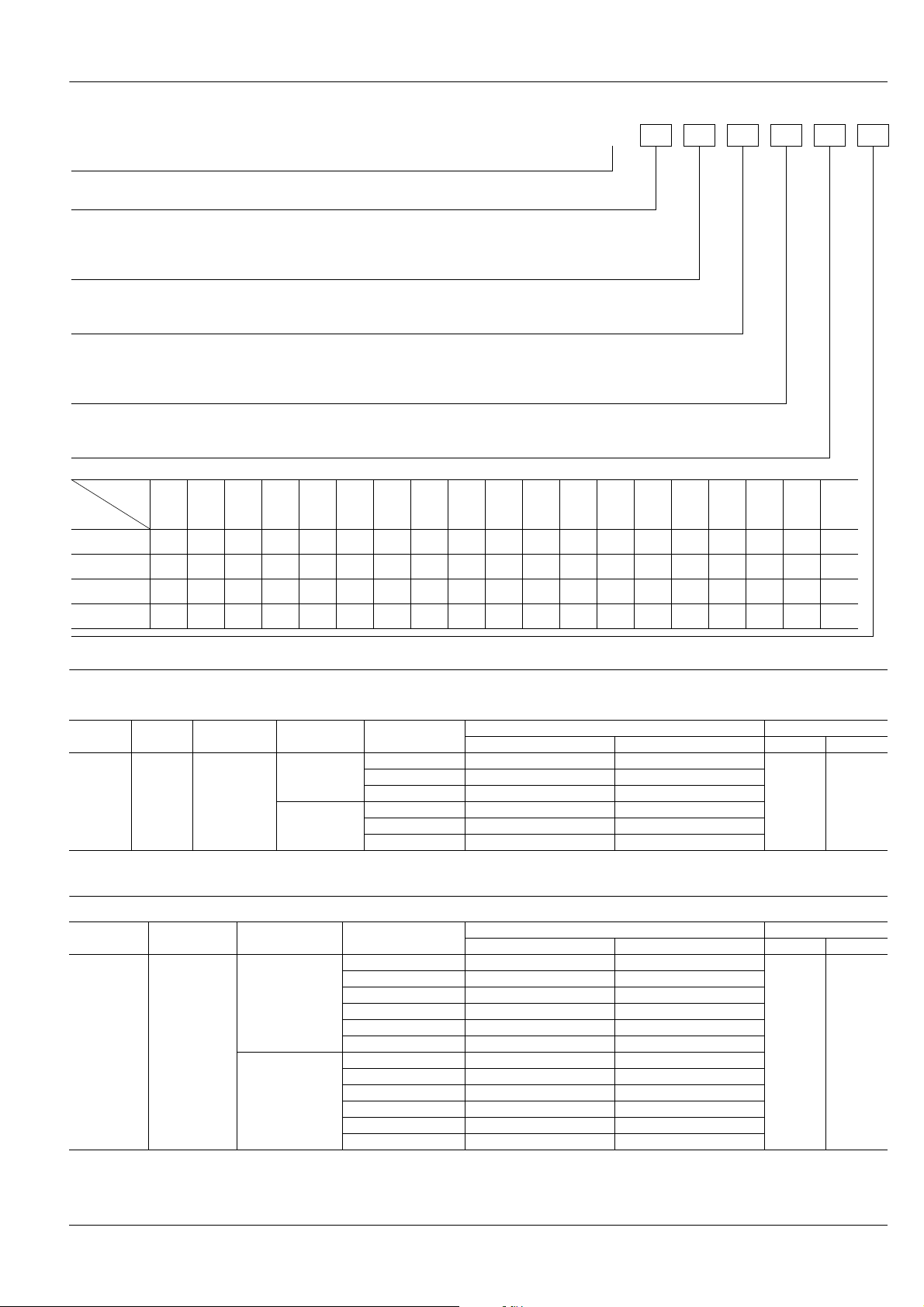
ORDERING INFORMATION
AM
MA Motion Sensor
A: Thin short type MA Motion sensor
B: MA Motion sensor
Detection distance type (shape)
1: Short type
2: Middle type
3: Long type
Triggering function
1: External triggering type
4: Built-in oscillation circuit type (Internal trigger)
Classification by output method & mounting direction
0: NPN open collector/H type
5: NPN open collector/V type
6: PNP open collector/V type
Operating voltage
2: Free-ranging power type (6.5 to 27V DC)
9: The DC 5V type (4.5 to 6.5V DC)
Rated detection distance inchcm
Part No.
Detection
distance
Thin short type — — —
Short type — — —
Middle type
Long type —
02 03 04 05 06 07
20 30 40 50 60 70 80
7.874 11.811 15.748 19.685 23.622 27.559 31.496
30 40 50 60 70 80 90 100 110 120 130 140 150 160 170 180 190 200
11.811 15.748 19.685 23.622 27.559 31.496 35.433 39.37 43.307 47.244 51.181 55.118 59.055 62.992 66.929 70.866 74.803 78.74
5
————
1.969 3.937 5.906
5678910
1.969 2.362 2.756 3.150 3.543 3.937
08
(Middle type
does not
need 08)
10
(Short type
09
————————————
11 12 13 14 15 16 17 18 19
does not
need 10)
10
————
——————————
15
—————
20
(Long type
does not
need 20)
DETECTION DISTANCE TYPE (distance limited)
1. Thin short type (V type)
Mounting
direction
V type
Note: If you plan to use multiple sensors side-by-side, or you wish to keep the current consumption small, inquire for details about external trigger type, which is suitable for
such applications.
Type
(shape)
Thin short
type
Operating
voltage
4.5 to 6.5 V DC
Output method
NPN open
collector output
PNP open
collector output
Rated detection
distance
5 cm 1.969 inch AMA145905 AMA115905
10 cm 3.937 inch AMA1459 AMA1159
15 cm 5.906 inch AMA145915 AMA115915
5 cm 1.969 inch AMA146905 AMA116905
10 cm 3.937 inch AMA1469 AMA1169
15 cm 5.906 inch AMA146915 AMA116915
Built-in oscillation circuit type External triggering type Inner Outer
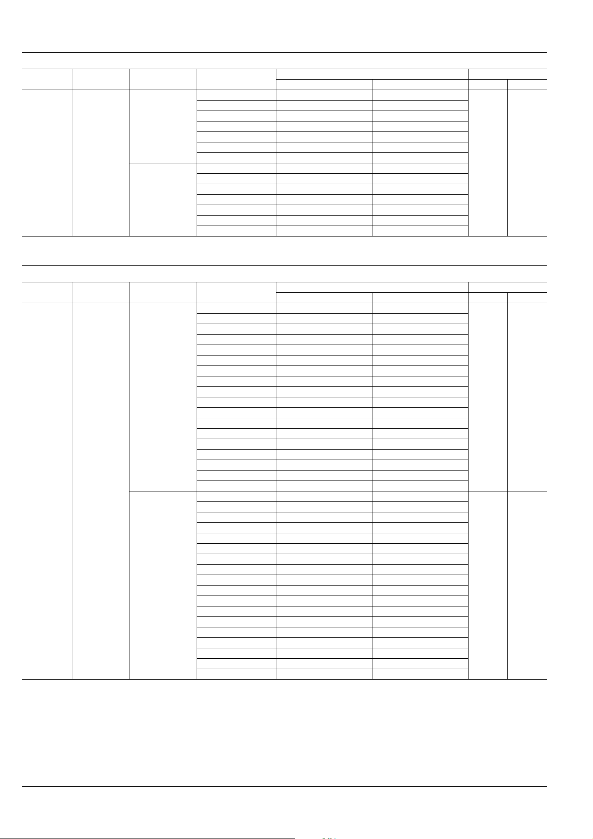
2. Short type (H type)
Mounting
direction
H type Short type
Note: If you plan to use multiple sensors side-by-side, or you wish to keep the current consumption small, inquire for details about external trigger type, which is suitable for
such applications.
Type (shape)
Rated operating
voltage
4.5 to 6.5 V DC
6.5 to 27 V DC
Rated detection
distance
5 cm 1.969 inch AMB140905 AMB110905
6 cm 2.362 inch AMB140906 AMB110906
7 cm 2.756 inch AMB140907 AMB110907
8 cm 3.150 inch AMB140908 AMB110908
9 cm 3.543 inch AMB140909 AMB110909
10 cm 3.937 inch AMB1409 AMB1109
5 cm 1.969 inch AMB140205 AMB110205
6 cm 2.362 inch AMB140206 AMB110206
7 cm 2.756 inch AMB140207 AMB110207
8 cm 3.150 inch AMB140208 AMB110208
9 cm 3.543 inch AMB140209 AMB110209
10 cm 3.937 inch AMB1402 AMB1102
Built-in oscillation circuit type External triggering type Inner Outer
Part No. Packing quantity
20 pcs. 200 pcs.
Part No. Packing quantity
20 pcs. 200 pcs.
All Rights Reserved © C
OPYRIGHT Panasonic Electric Works Co., Ltd.
Page 3
MA Motion Sensor (AMA1, AMB1, 2, 3)
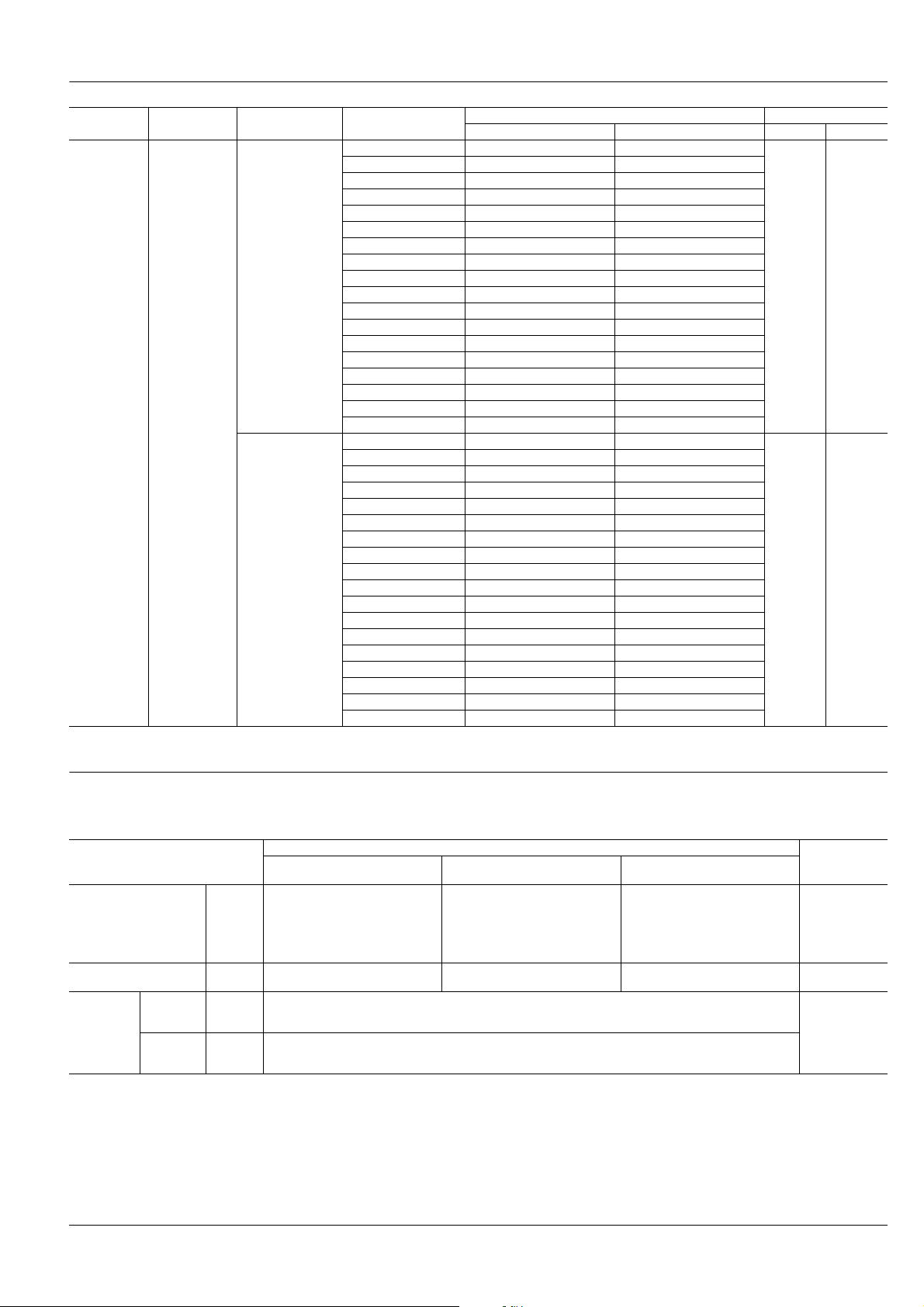
3. Middle type (H type)
Mounting
direction
H type Middle type
Note: If you plan to use multiple sensors side-by-side, or you wish to keep the current consumption small, inquire for details about external trigger type, which is suitable for
such applications.
Type (shape)
Rated operating
voltage
4.5 to 6.5 V DC
6.5 to 27 V DC
Rated detection
distance
20 cm 7.874 inch AMB240902 AMB210902
30 cm 11.811 inch AMB240903 AMB210903
40 cm 15.748 inch AMB240904 AMB210904
50 cm 19.685 inch AMB240905 AMB210905
60 cm 23.622 inch AMB240906 AMB210906
70 cm 27.559 inch AMB240907 AMB210907
80 cm 31.496 inch AMB2409 AMB2109
20 cm 7.874 inch AMB240202 AMB210202
30 cm 11.811 inch AMB240203 AMB210203
40 cm 15.748 inch AMB240204 AMB210204
50 cm 19.685 inch AMB240205 AMB210205
60 cm 23.622 inch AMB240206 AMB210206
70 cm 27.559 inch AMB240207 AMB210207
80 cm 31.496 inch AMB2402 AMB2102
Built-in oscillation circuit type External triggering type Inner Outer
4. Long type (H type)
Mounting
direction
H type Long type
Note: If you plan to use multiple sensors side-by-side, or you wish to keep the current consumption small, inquire for details about external trigger type, which is suitable for
such applications.
Type (shape)
Rated operating
voltage
4.5 to 6.5 V DC
6.5 to 27 V DC
Rated detection
distance
30 cm 11.811 inch AMB340903 AMB310903
40 cm 15.748 inch AMB340904 AMB310904
50 cm 19.685 inch AMB340905 AMB310905
60 cm 23.622 inch AMB340906 AMB310906
70 cm 27.559 inch AMB340907 AMB310907
80 cm 31.496 inch AMB340908 AMB310908
90 cm 35.433 inch AMB340909 AMB310909
100 cm 39.370 inch AMB340910 AMB310910
110 cm 43.307 inch AMB340911 AMB310911
120 cm 47.244 inch AMB340912 AMB310912
130 cm 51.181 inch AMB340913 AMB310913
140 cm 55.118 inch AMB340914 AMB310914
150 cm 59.055 inch AMB340915 AMB310915
160 cm 62.992 inch AMB340916 AMB310916
170 cm 66.929 inch AMB340917 AMB310917
180 cm 70.866 inch AMB340918 AMB310918
190 cm 74.803 inch AMB340919 AMB310919
200 cm 78.740 inch AMB3409 AMB3109
30 cm 11.811 inch AMB340203 AMB310203
40 cm 15.748 inch AMB340204 AMB310204
50 cm 19.685 inch AMB340205 AMB310205
60 cm 23.622 inch AMB340206 AMB310206
70 cm 27.559 inch AMB340207 AMB310207
80 cm 31.496 inch AMB340208 AMB310208
90 cm 35.433 inch AMB340209 AMB310209
100 cm 39.370 inch AMB340210 AMB310210
110 cm 43.307 inch AMB340211 AMB310211
120 cm 47.244 inch AMB340212 AMB310212
130 cm 51.181 inch AMB340213 AMB310213
140 cm 55.118 inch AMB340214 AMB310214
150 cm 59.055 inch AMB340215 AMB310215
160 cm 62.992 inch AMB340216 AMB310216
170 cm 66.929 inch AMB340217 AMB310217
180 cm 70.866 inch AMB340218 AMB310218
190 cm 74.803 inch AMB340219 AMB310219
200 cm 78.740 inch AMB3402 AMB3102
Built-in oscillation circuit type External triggering type Inner Outer
Part No. Packing quantity
20 pcs. 200 pcs.
Part No. Packing quantity
20 pcs. 200 pcs.
20 pcs. 200 pcs.
All Rights Reserved © C
OPYRIGHT Panasonic Electric Works Co., Ltd.
Page 4
MA Motion Sensor (AMA1, AMB1, 2, 3)
5. Long type (V type)
Mounting
direction
V type Long type
Note: If you plan to use multiple sensors side-by-side, or you wish to keep the current consumption small, inquire for details about external trigger type, which is suitable for
such applications.
Type (shape)
Rated operating
voltage
4.5 to 6.5 V DC
6.5 to 27 V DC
Rated detection
distance
30 cm 11.811 inch AMB345903 AMB315903
40 cm 15.748 inch AMB345904 AMB315904
50 cm 19.685 inch AMB345905 AMB315905
60 cm 23.622 inch AMB345906 AMB315906
70 cm 27.559 inch AMB345907 AMB315907
80 cm 31.496 inch AMB345908 AMB315908
90 cm 35.433 inch AMB345909 AMB315909
100 cm 39.370 inch AMB345910 AMB315910
110 cm 43.307 inch AMB345911 AMB315911
120 cm 47.244 inch AMB345912 AMB315912
130 cm 51.181 inch AMB345913 AMB315913
140 cm 55.118 inch AMB345914 AMB315914
150 cm 59.055 inch AMB345915 AMB315915
160 cm 62.992 inch AMB345916 AMB315916
170 cm 66.929 inch AMB345917 AMB315917
180 cm 70.866 inch AMB345918 AMB315918
190 cm 74.803 inch AMB345919 AMB315919
200 cm 78.740 inch AMB3459 AMB3159
30 cm 11.811 inch AMB345203 AMB315203
40 cm 15.748 inch AMB345204 AMB315204
50 cm 19.685 inch AMB345205 AMB315205
60 cm 23.622 inch AMB345206 AMB315206
70 cm 27.559 inch AMB345207 AMB315207
80 cm 31.496 inch AMB345208 AMB315208
90 cm 35.433 inch AMB345209 AMB315209
100 cm 39.370 inch AMB345210 AMB315210
110 cm 43.307 inch AMB345211 AMB315211
120 cm 47.244 inch AMB345212 AMB315212
130 cm 51.181 inch AMB345213 AMB315213
140 cm 55.118 inch AMB345214 AMB315214
150 cm 59.055 inch AMB345215 AMB315215
160 cm 62.992 inch AMB345216 AMB315216
170 cm 66.929 inch AMB345217 AMB315217
180 cm 70.866 inch AMB345218 AMB315218
190 cm 74.803 inch AMB345219 AMB315219
200 cm 78.740 inch AMB3452 AMB3152
Built-in oscillation circuit type External triggering type Inner Outer
Part No. Packing quantity
20 pcs. 200 pcs.
20 pcs. 200 pcs.
PERFORMANCE
1. Detection performance (Measuring conditions: ambient temp.: 25°C 77°F; operating voltage: 5 V DC)
1) Thin short type
Items
Minimum
Rated detection distance
Measuring tolerance Typical 10% 25% 35%
Usable
ambient
brightness
(Resistance
to ambient
light)*
Notes: *1. Ambient brightness: 500 lx
Brightness
of sensor
surface
Brightness
of reflection
2
surface
*2. Install so that light from direct light sources does not enter the sensor (within 30° of the sensor light beam).
Indicates brightness detectible enough for sensor operation. (Measuring conditions: ambient temp.: 25°C 77°F; operating voltage: 5 V DC type 5V, Free-ranging
power type 24V DC)
Typical
Maximum
Maximum 30,000 lx
Maximum 30,000 lx
All Rights Reserved © C
5 cm
1.969 inch
45 mm
1.772 inch
50 mm
1.969 inch
55 mm
2.165 inch
OPYRIGHT Panasonic Electric Works Co., Ltd.
Thin short type
10 cm
3.937 inch
90 mm
3.543 inch
100 mm
3.937 inch
110 mm
4.331 inch
15 cm
3.937 inch
135 mm
5.315 inch
150 mm
5.906 inch
165 mm
6.496 inch
Measured
conditions
with a standard
reflection
1
board*
Reflection rate:
90 to 18%
See the drawing
(Fig. 1) on the
next page.
Page 5

MA Motion Sensor (AMA1, AMB1, 2, 3)
2) Short type
50 cm
475 mm
500 mm
525 mm
1
8 cm
3.150 inch
72 mm
2.835 inch
80 mm
3.150 inch
88 mm
3.465 inch
1
23.622 inch
570 mm
22.441 inch
600 mm
23.622 inch
630 mm
24.803 inch
60 cm
9 cm
3.543 inch
81 mm
3.189 inch
90 mm
3.543 inch
99 mm
3.898 inch
70 cm
27.559 inch
665 mm
26.181 inch
700 mm
27.559 inch
735 mm
28.937 inch
10 cm
3.937 inch
90 mm
3.543 inch
100 mm
3.937 inch
110 mm
4.331 inch
31.496 inch
760 mm
29.921 inch
800 mm
31.496 inch
840 mm
33.071 inch
Items
Minimum
Rated detection distance
Measuring tolerance Typical 10% 15% 20% 25%
Usable
ambient
brightness
(Resistance
to ambient
light)*
Notes: *1. After receipt of order, average rated detection distance to 15 cm 5.906 inch is possible. Please inquire.
3) Middle type
Rated detection distance
Measuring tolerance Typical 3% 5% 10%
Usable
ambient
brightness
(Resistance
to ambient
light)*
Notes: *1. After receipt of order, average rated detection distance to 110 cm 43.307 inch is possible. Please inquire.
Brightness
of sensor
surface
Brightness
of reflection
2
surface
*2. Install so that light from direct light sources does not enter the sensor (within 30° of the sensor light beam).
(Measuring conditions: ambient temp.: 25°C 77°F; operating voltage: 5 V DC type 5V, Free-ranging power type 24V DC)
Items
Brightness
of sensor
surface
Brightness
of reflection
2
surface
*2. Install so that light from direct light sources does not enter the sensor (within 30° of the sensor light beam).
Typical
Maximum
Maximum 30,000 lx
Maximum 30,000 lx
Minimum
Typical
Maximum
Maximum 30,000 lx
Maximum 30,000 lx
5 cm
1.969 inch
45 mm
1.772 inch
50 mm
1.969 inch
55 mm
2.165 inch
20 cm
7.874 inch
190 mm
7.480 inch
200 mm
7.874 inch
210 mm
8.268 inch
6 cm
2.362 inch
54 mm
2.126 inch
60 mm
3.362 inch
66 mm
2.598 inch
30 cm
11.811 inch
285 mm
11.220 inch
300 mm
11.811 inch
315 mm
12.402 inch
40 cm
15.748 inch
380 mm
14.961 inch
400 mm
15.748 inch
420 mm
16.535 inch
Short type*
7 cm
2.756 inch
63 mm
2.480 inch
70 mm
2.756 inch
77 mm
3.031 inch
Middle type*
19.685 inch
18.701 inch
19.685 inch
20.669 inch
80 cm
Measured
conditions
with a standard
reflection board
Reflection rate:
90 to 18%
See the drawing
(Fig. 1) on the
next page.
Measured
conditions
with a standard
reflection board
Reflection rate:
90 to 18%
See the drawing
(Fig. 1) on the
next page.
4) Long type (Measuring conditions: ambient temp.: 25°C 77°F; operating voltage: 5 V DC type 5V, Free-ranging power type 24V DC)
Items
Minimum
Rated detection distance
Measuring tolerance Typical 3% 5%
Usable
ambient
brightness
(Resistance
to ambient
light)*
Rated detection distance
Measuring tolerance Typical 5% 10% 15%
Usable
ambient
brightness
(Resistance
to ambient
light)*
Note: * Install so that light from direct light sources does not enter the sensor (within 30° of the sensor light beam).
Brightness
of sensor
surface
Brightness
of reflection
surface
Items
Brightness
of sensor
surface
Brightness
of reflection
surface
Typical
Maximum
Maximum 30,000 lx
Maximum 30,000 lx
Minimum
Typical
Maximum
Maximum 30,000 lx
Maximum 30,000 lx
30 cm
11.811 inch
285 mm
11.220 inch
300 mm
11.811 inch
315 mm
12.402 inch
120 cm
47.244 inch
1140 mm
44.882 inch
1200 mm
47.244 inch
1260 mm
49.606 inch
40 cm
15.748 inch
380 mm
14.961 inch
400 mm
15.748 inch
420 mm
16.535 inch
130 cm
51.181 inch
1235 mm
48.622 inch
1300 mm
51.181 inch
1365 mm
53.740 inch
50 cm
19.685 inch
475 mm
18.701 inch
500 mm
19.685 inch
525 mm
20.669 inch
140 cm
55.118 inch
1330 mm
52.362 inch
1400 mm
55.118 inch
1470 mm
57.874 inch
60 cm
23.622 inch
570 mm
22.441 inch
600 mm
23.622 inch
630 mm
24.803 inch
150 cm
49.055 inch
1425 mm
56.102 inch
1500 mm
59.055 inch
1575 mm
62.008 inch
Long type
70 cm
27.559 inch
665 mm
26.181 inch
700 mm
27.559 inch
735 mm
28.937 inch
Long type
160 cm
62.992 inch
1520 mm
59.842 inch
1600 mm
62.992 inch
1680 mm
66.142 inch
80 cm
31.496 inch
760 mm
29.921 inch
800 mm
31.496 inch
840 mm
33.071 inch
170 cm
66.929 inch
1615 mm
63.583 inch
1700 mm
66.929 inch
1785 mm
70.275 inch
90 cm
35.433 inch
855 mm
33.661 inch
900 mm
34.433 inch
945 mm
37.205 inch
180 cm
70.866 inch
1710 mm
67.323 inch
1800 mm
70.866 inch
1890 mm
74.409 inch
100 cm
39.37 inch
950 mm
37.402 inch
1000 mm
39.37 inch
1050 mm
41.339 inch
190 cm
74.803 inch
1805 mm
71.063 inch
1900 mm
74.803 inch
1995 mm
78.543 inch
110 cm
43.307 inch
1045 mm
41.142 inch
1100 mm
43.307 inch
1155 mm
45.472 inch
200 cm
78.74 inch
1900 mm
74.803 inch
2000 mm
78.74 inch
2100 mm
82.677 inch
Measured
conditions
with a standard
reflection board
Reflection rate:
90 to 18%
See the drawing
(Fig. 1) on the
next page.
Measured
conditions
with a standard
reflection board
Reflection rate:
90 to 18%
See the drawing
(Fig. 1) on the
next page.
All Rights Reserved © C
OPYRIGHT Panasonic Electric Works Co., Ltd.
Page 6

•For thin short type:
a – b
a
Standard reflection board: 100 mm 3.937 inch square area,
90% reflection rate.
•For short type:
Standard reflection board: 100 mm 3.937 inch square area,
90% reflection rate.
•For middle type:
Standard reflection board: 200 mm 7.874 inch square area,
90% reflection rate.
•For long type:
Standard reflection board: 500 mm 19.685 inch square area,
90% reflection rate.
<Fig. 1>
[Brightness of sensor surface]
, θ1′) > 15°
(θ
Light meter
30°
1
❇Area for prohibit
θ
1
direct light
θ
1′
Sensor
Note: Light from direct light sources (sunlight, strobe light, inverter illumination,
reflected light from glass or mirrors etc.) that enters the sensor from within
the prohibited range can cause the sensor to operate erroneously.
MA Motion Sensor (AMA1, AMB1, 2, 3)
Notes: 1. Detecting an object within the maximum preset detection distance.
2. Distance deviation = × 100 (%)
a: detection distance of detection target with reflectance of 90%.
b: detection distance of standard detection target with reflectance of 18%.
[Brightness of reflection surface]
Sensor
30°*(θ2, θ2′)*45°
Rated detection distance
θ
2
θ
2′
Light meter
Reflection
board
2. Absolute maximum rating (Measuring condition: ambient temp.: 25°C 77°F)
Items
Type
Power supply voltage –0.3 to 8 V DC –0.3 to 30 V DC –0.3 to 8 V DC –0.3 to 30 V DC
Output dielectric strength 30 V 30 V
Output flow current 100 mA 10 mA*
Usable ambient temperature –25 to +75°C +5 to +131°F (No freezing) –25 to +75°C +5 to +131°F (No freezing)
Storage temperature –30 to +85°C –4 to +176°F –30 to +85°C –4 to +176°F
Note: * Thin short type is only: 100 mA
Built-in oscillation circuit type External triggering type
5 V DC type Free-ranging power type 5 V DC type Free-ranging power type
3. Electrical characteristics
(Measuring conditions: ambient temp.: 25°C 77°F; operating voltage: 5 V DC type =5V DC, free-ranging power type =24V DC)
1) Built-in oscillation circuit type
Thin short type*
Items Symbol
Minimum
Rated operating voltage
Average current
consumption
(Iout = 0 mA)
Measuring cycle Minimum T 8ms/cycle
Output
characteristics
Note: * The thin short type is only available for 5V DC.
No detection
Detection
Remain voltage Maximum Vr 1 V DC 1.2 V DC 1 V DC It = 100 mA
Leakage current Maximum Il 5µA 3µA V = 30V
Typical —
Maximum 5V DC type: 6.5V/Free-ranging power type: 27V
Minimum
Typical 4.5mA 5V DC type: 4.5mA/Free-ranging power type: 5.6mA
Maximum 6.2mA 5V DC type: 6.2mA/Free-ranging power type: 7.8mA
Minimum
Typical 7.0mA 11.0mA 5V DC type: 7.0mA/Free-ranging power type: 9.1mA
Maximum 11.2mA 15.2mA 5V DC type: 11.2mA/Free-ranging power type: 14.2mA
Vdd
NPN
output
type
It
It
PNP
output
type
5V DC type: 4.5V/Free-ranging power type: 6.5V
Short type Middle type Long type Measured conditions
—
—
All Rights Reserved © C
OPYRIGHT Panasonic Electric Works Co., Ltd.
Page 7

MA Motion Sensor (AMA1, AMB1, 2, 3)
2) External triggering type (trigger conditions: trigger pulse width = 20µs and trigger synchronization = 5ms)
Thin short type
Items Symbol
Minimum
Rated operating voltage
Typical —
Vdd
Maximum 5V DC type: 6.5V/Free-ranging type: 27V
Minimum
Average current
consumption
Without
trigger input
With trigger
input
Output OFF
Maximum 0.3m 5V DC type: 0.3mA/Free-ranging type: 1.8mA
Minimum
Output ON
Maximum 6.6mA 9.6mA 5V DC type: 3.4mA/Free-ranging type: 4.5mA
Minimum
Output OFF
Maximum 6.2mA 5V DC type: 6.2mA/Free-ranging type: 7.2mA
Minimum
Output ON
Ib
Id
Ia
Ic
Maximum 8.2mA 12.5mA 5V DC type: 8.2mA/Free-ranging type: 9.3mA
Measuring cycle (Trigger interval) Minimum Tt 5ms/cycle
Pulse width
External trigger
Level
Response performance:
time from trigger pulse fall to detection output
Output
characteristics
Remain voltage Maximum Vr 1 V DC 1.2 V DC 1 V I = 10 mA
Leakage current Maximum Il 5µA 3µA V = 30 mA
Minimum
Maximum 1/2Tt Half off the distance period
Maximum V
Tw
TL 0.8V
Minimum VTH 3V Note 3
Maximum Tr 5ms
Notes: 1. The thin short type is only available for 5V DC.
2. The ratio between the 4 operating modes (*a to *d) depends on the
external trigger period and detector time, and the current consumption
corresponds with this varying ratio.
Trigger input
*a *b *c *d
Operation
Internal sensor
operation
Output transistor
Stand by
OFF
OFF
ON
2 ms
(approx.)
(With trigger input)
2 ms
(approx.)
(Without trigger input)
2 ms
(approx.)
(With trigger input)
(approx.)
Non-detection status Detection status
(The output is latched
by the previous trigger.)
(The output is latched
by the previous trigger.)
2 ms
(Without trigger input)
3. A high level is established in the open state due to pull-up by the internal
circuit. (Refer to the connector wiring diagram.)
NPN
output
type
Note 1
PNP
Short type Middle type Long type Measured conditions
output
type
5V DC type: 4.5V/Free-ranging type: 6.5V
—
—
—
—
20µs
4. The output transistor is open collector.
The output transistor is turned ON by the sensor detection status and
turned OFF by its non-detection status.
Detection status:
output transistor ON
Non-detection status:
output transistor OFF
Detection status:
output transistor ON
Non-detection status:
output transistor OFF
Sensor
(NPN output types of the AMA series and all of AMB series)
Sensor
(PNP output types of the AMA series)
Output
transistor
Output
transistor
Note 2: *bTypical 0.1m 5V DC type: 0.1mA/Free-ranging type: 1.0mA
Note 2: *dTypical 2.6mA 6.7mA 5V DC type: 0.5mA/Free-ranging type: 1.4mA
Note 2: *aTypical 2.2mA 5V DC type: 2.2mA/Free-ranging type: 3.1mA
Note 2: *cTypical 4.2mA 6.2mA 5V DC type: 2.4mA/Free-ranging type: 3.3mA
Output
GND
Output
TIMING CHART
1. Built-in oscillation circuit type
(NPN output types of the AMA series and all of AMB series)
Power supply
Output transistor
(open collector)
ON
OFF
OFF
ON
Circuit
stability
time
Non-detection
status
Detection
status
Non-detection
status
Power supply
Output transistor
(open collector)
Notes: 1. Circuit stability time : Max. 12 ms
2. During the time taken for the circuit to stabilize after the power is turned on, the ON/OFF status of the output transistor is not determined by whether the sensor is
in the detection status or non-detection status.
All Rights Reserved © C
OPYRIGHT Panasonic Electric Works Co., Ltd.
(PNP output types of the AMA series)
ON
OFF
ON
OFF
Circuit
Non-detection
stability
status
time
Detection
status
Non-detection
status
Page 8

2. External triggering type
Power supply
External trigger
Output transistor
(open collector)
NPN output types
•
of the AMA series
AMB series
•
ON
OFF
VTH
VTL
OFF
ON
Circuit
stability
time
detection
status
Non-
Detection
status
Non-
detection
status
MA Motion Sensor (AMA1, AMB1, 2, 3)
Tt: Min. 5ms
Tr : M ax. 5ms
External trigger
Output
VTH
VTL
Tw
Change
(ON to OFF or
OFF to ON)
Output transistor
PNP output types
•
of the AMA series
ON
OFF
Circuit
stability
time
Non-
detection
status
Detection
status
Non-
detection
status
Notes: 1. Circuit stability time : Max. 12 ms
2. During the time taken for the circuit to stabilize after the power is turned
on, the ON/OFF status of the output transistor is not determined by
whether the sensor is in the detection status or non-detection status.
HOW TO USE
• Wiring diagram of connector
Built-in oscillation circuit type External triggering type
+
Min.
+
33 µF
Note 3.
NPN output type
N.C.
(No connection)
Power supply
4
GND
3
2
Note: The sensor recognizes at the V
external trigger has been input.
Output
1
Tr
Note 1.
External trigger input
Note 2.
TH → VTL edge of an external trigger that the
+
Min.
+
33 µF
Note 3.
Power supply
4
GND
3
Output
1
Note 1.
2
PNP output type
N.C.
(No connection)
Power supply
4
GND
+
Min.
+
33 µF
Note 3.
Note 2.
Power supply
4
3
Output
Tr
Note 1.
1
2
External trigger input
GND
+
Min.
+
33 µF
Note 3.
3
2
Notes: 1. The output transistor has an open collector structure.
• Detection status: Output transistor ON (connected to GND)
• Non-detection status: Output transistor OFF (open state)
2. The status of the external trigger input is as follows:
• Open at the high level
• GND (less than 0.8V) at the low level
Under no circumstances must a high-level voltage be applied.
3. To maintain the power supply noise performance, be certain to connect a capacitor (33µF or more) to the sensor power supply input terminal in order to stabilize
the power supply voltage.
Output
Note 1.
1
All Rights Reserved © C
OPYRIGHT Panasonic Electric Works Co., Ltd.
Page 9

MA Motion Sensor (AMA1, AMB1, 2, 3)
Detection width W (mm inch)
Detection distance L (mm inch)
0
10
.394
10
.394
20
.787
20
.787
0
100
3.937
10
.394
20
.787
30
1.181
40
1.575
50
1.969
60
2.362
70
2.756
80
3.150
90
3.543
Operating area
within the dotted lines
Operating region for
rated detection
distance of 8 cm
3.150 inch
Objects that enter the entire area are detected.
Operating area within the dotted lines
Object
Operating area
within the solid lines
Object
Objects that even partially enter the area are detected.
Operating area within the solid lines
Note: If only part of the object is in the detection area, it is not
detected.
0
250
9.843
500
19.685
750
29.528
1000
39.37
1250
49.213
1500
59.055
1750
68.898
2000
78.74
Reflection board
500 × 500 mm
19.685 × 19.685 inch
(reflectivity: 90%)
150 cm
59.055 inch
100 cm
39.37 inch
50 cm
19.685 inch
Y
X
Reflection
board
30
1.181
40
1.575
40
Detection width W (mm inch)
Detection distance L (mm inch)
0
10
.394
10
.394
30
1.181
20
.787
20
.787
Operating region for
rated detection distance
of 200 cm 78.74 inch
REFERENCE DATA
Operating region characteristics
• How to interpret the graph
Example: Operating area of the Short Type
with rated detection distance of
8 cm 3.150 inch.
(1) Thin short type (AMA14)
(2) Middle type (AMB24) (3) Long type (AMB34)
Short type (AMB14)
Detection distance L (mm inch)
3.937
3.543
3.150
2.756
2.362
1.969
1.575
1.181
.787
.394
100
90
80
70
60
50
40
30
20
10
0
Reflection
board
Reflection board
200 × 200 mm
7.874 × 7.874 inch
(reflectivity: 90%)
Y
X
20
.787
Detection width W (mm inch)
Operating region for
rated detection distance
of 10 cm 3.937 inch
0
20
.787
10
10
.394
.394
9 cm 3.534 inch
8 cm 3.150 inch
7 cm 2.756 inch
6 cm 2.362 inch
5 cm 1.969 inch
31.496
27.559
23.622
19.685
15.748
11.811
Detection distance L (mm inch)
7.874
3.937
800
700
600
500
400
300
200
100
Reflection board
200 × 200 mm
7.874 × 7.874 inch
(reflectivity: 90%)
Reflection
board
0
Y
X
20
40
.787
1.575
10
30
.394
1.181
Detection width W (mm inch)
0
20
.787
10
.394
1.181
Operating region for
rated detection distance
of 80 cm 31.496 inch
70 cm
27.559 inch
60 cm
23.622 inch
50 cm
19.685 inch
40 cm
15.748 inch
30 cm
11.811 inch
20 cm
7.874 inch
40
30
DIMENSIONS (Common to the Built-in oscillation circuit type and External triggering type)
1) Thin short type (V) 2) Short type (H)
2-R3.25
2-R.128
Stamped side
(one side only)
10.0
.394
12.7
.500
11.0
.433
.260
6.6
29.0
1.142
20.0
.787
*Rear side connector protrusion: Max. 0.4mm
6.5
.256
Receiver
Projector
4
.157
16
.630
16.25
.640
10
Connector surface
.394
(Front lens surface)
11
.433
20
.787
22.5
.886
2.5 dia.
.098 dia.
Optical surface
19.5
.768
.236
mm inch
6
3) Middle type (H)
22
.866
19.35
.762
Receiver
Projector
5
.197
.551
29.5
1.161
3.1 dia.
.122 dia.
Connector surface
(Front lens surface)
Optical surface
31.2
1.228
14
23.1
.909
0.4
.016
All Rights Reserved © C
OPYRIGHT Panasonic Electric Works Co., Ltd.
Page 10

MA Motion Sensor (AMA1, AMB1, 2, 3)
4) Long type (H) Long type (V)
33
.394
10
1.299
4.2 dia.
.165 dia.
Connector surface
24.7
.972
(Front lens surface)
Optical surface
20
.787
10
.394
4.2 dia.
.165 dia.
Optical
surface
.276
7
Connector
surface
Receiver
Projector
7
.276
20
.787
43
1.693
46
1.811
29.7
1.169
Max. 1
.039
Receiver
Projector
46
1.811
55
2.165
WIRING DIAGRAM (Connector surface view)
1) Thin short type (V) 2) Short type (H) 3) Middle type (H)
IL-Z-4P-S125L3-E
BM04B-SRSS
(J.S.T. Mfg. Co., Ltd.)
1: Output
2: GND
4321
3: Power source
4. Built-in oscillation circuit type: N.C.
External triggering type:
external trigger input
4) Long type (H) Long type (V)
IL-Z-4P-S125T3-E
(Japan Aviation Electronics Industry,
Limited)
1: Output
1
2
3
4
2: GND
3: Power source
4. Built-in oscillation circuit type: N.C.
External triggering type:
external trigger input
(Japan Aviation Electronics Industry,
Limited)
1
1: Output
2
3
4
2: GND
3: Power source
4. Built-in oscillation circuit type: N.C.
External triggering type:
external trigger input
IL-Z-4P-S125T3-E
(Japan Aviation Electronics Industry,
Limited)
1: Output
2: GND
3: Power source
1
2
3
4
4. Built-in oscillation circuit type: N.C.
External triggering type:
external trigger input
IL-Z-4P-S125T3-E
(Japan Aviation Electronics Industry,
Limited)
1
1: Output
2
3
2: GND
4
3: Power source
4. Built-in oscillation circuit type: N.C.
Notes: Purchase the follwing connections:
1. Socket housing IL-Z-4S-S125C3
(Japan Aviation Electronic Industry, Ltd.)
2. Lead wire (with metal connector at one end)
65
2.559
29.7
1.169
MAX. 1
.039
External triggering type:
external trigger input
OPTIONAL
1. Connector with cable (for AMB series)
AMV9001
Lead wires AWG 28
4.3
.169
6.45
.254
(Japan Aviation Electronics Industry, Limited)
All Rights Reserved © C
1. Output (Black)
2. GND (Blue)
3. Power source (Brown)
4. Built-in oscillation circuit type: N.C.
External triggering type: external trigger input (Purple)
150±5
5.906±.197
Socket housing IL-Z-4S-S125C3
OPYRIGHT Panasonic Electric Works Co., Ltd.
The edge is soldered
4.5±1
.177±.039
mm inch
Note: Mistaken cable assembly can cause
damage to the internal circuits, so please
check the power cord before switching
ON. (Par ticular care must be taken as to
avoid reverse connection of the power.)*Connectors with cable for thin short type are handled as “U orders”.
Page 11

MA Motion Sensor (AMA1, AMB1, 2, 3)
NOTES
1. Environment
1) Avoid using the sensor in
environments containing excessive
amounts of steam, dust, corrosive gas, or
where organic solvents are present.
2) When the sensor is used in noisy
environments, connect a capacitor
(minimum 33 µF) across its power input
terminals.
2. Wiring
1) Check all wiring before applying
power. Incorrect wiring may damage the
internal circuit (in particular, check that
the connection to the power supply is not
reversed.)
2) Avoid excessive removing and
replacing of the connector.
3. Detector surface (Optical surface)
1) Keep the detector surface clean.
Excessive dust or dirt on the detector
surface will deteriorate the sensing
performance.
2) Do not allow condensation or freezing
to occur on the surface of the sensor. If
condensation or freezing does occur at
low temperatures, the sensor may not
detect objects correctly.
3) This product is designed to detect the
existence of human body. The sensor will
not detect objects consisting of a low
reflective material (e.g., an object coated
with black rubber, etc.) or of a highly
reflective material (e.g., mirror, glass,
coated paper, etc.)
4) The front surface of the lens and case
are made of polycarbonate resin and can
withstand water, alcohol, oils, salts and
weak acids. Other fluids such as
alkalines, aromatic hydrocarbons and
halogenated hydrocarbons may melt or
swell the lens and case, please do not
have such fluids touch the lens and case.
5) If you use the sensor with a cover or
filter connected to the front of the sensor,
the sensor may detect the cover itself, the
detection distance can change, and
unstable operation can result.
6) When multiple sensors are to be used
side by side, please verify that there will
be no mutual interference by installing
them with the proper spacing, depending
on the type as shown below.
Model number Sensor spacing
AMB1 series 5 cm 1.969 inch
AMA1 series 8 cm 3.150 inch
AMB2 series 10 cm 3.937 inch
AMB3 series 20 cm 7.874 inch
7) To protect the inner circuit, wiring
should be max. 3 m 9.843 ft..
4. Recommended installation
procedure
Install the photoelectric sensor so that it
is orientated correctly in relation to the
pass directions of the target objects as
shown in the figure below.
Y
Z
Pass
directions
Pass directions
Pass
directions
Object
❈ → stands for pass direction of the target object.
X
Object
Object
For the general precautions, refer to the
Notes for Motion Sensors on next page.
All Rights Reserved © C
OPYRIGHT Panasonic Electric Works Co., Ltd.
 Loading...