

Page 1

M2X Series Inverter
for
3-phase Induction Motor Speed Control
INSTRUCTION MANUAL
Be sure to hand over this instruction manual to customers.
● Thank you for purchasing Panasonic Inverter.
● To ensure proper use of this product, read this instruction manual
thoroughly.
Keep this manual in place, and read it whenever required.
Page 2

Contents
Before startup
Preparation and
adjustment
Safety Precautions
Introduction
• Unpacking and inspection
• Checking the inverter model
System Configuration and Wiring
• Wiring general view
• Inverter and applicable
• Wiring
• Changing the input signal logic
• Terminal function
・・・・・・・・・・・・・・・・・・・・・・・
peripheral equipment
・・・・・・・・・・・・・・・・・・・・・・・・・・・・・・・
・・・・・・・・・・・・・・・・・
・・・・・・・・・・・・・・
・・・・・・・・・・・・
・・・・・・・・・・・・・・・・・・・・
・・・・・・・・・
・・・・・・・・・・
・・・・・・・・・・・・・・・・・・・・・・
・・
4
8
8
8
12
12
13
14
16
17
If necessary
Application
Specifications
Protective Function
• Protective functions
• Canceling trip
・・・・・・・・・・・・・・・・・・・・・・・・・
・・・・・・・・・・・・・・・
・・・・・・・・・・・・・・・・・・・・
Parameter Description
Detailed Parameter Description
• Function of parameter
(Parameter initialization
Specifications
Dimensions
・・・・・・・・・・・・・・・・・・・・
・・・・・・・・・・・・・・・・・・・・・・
・・・・・・・・・・・・
・・・・・・・・・・・・・・・・・
・・・・・・・・・・・・・・・・・・・
・・・・
33
33
36
39
45
45
59)
67
68
Conformity to EC Directive /
UL Standard
- 2 -
・・・・・・・・・・・・・・・・・・・・・・
69
Page 3

Parts Description
• Outline and Part Names
CAUTION
• Instructions for safe and
correct operation
• Precautions when wiring
Parameter Setting
• Setting
Test Operation
• Pre-operation inspections
• Tes t ru n
・・・・・・・・・・・・・・・・・・・・・・・・・
・・・・・・・・・・・・・・・・・・・・・・・・・・・・・・
・・・・・・・・・・・・・・・・・・・・・・・・・・・・・
・・・・・・・・・・・・・・・・・・
・・・・・・・・・・・・・・・・
・・・・・・・・・・・・・・・・・・・・・・
・・・・・・・・・・・・・・・
・・・・・・・・・・・・・・・・・
・・・・・・・・・・・・・・・・・・・・
・・・・・・・・・・・・・・
9
9
10
10
20
21
21 • Selection of the run command
23
23 • Acceleration/deceleration time
23
Installation
Operation Function
• Frequency command selection
・・・・・・・・・・・・・・・・・・・・・・・
・・・・・・・・・・・・・・・
・・・・・・・・・・
changing procedure
changing procedure
・・・・・・・・・・
・・・・・・・・・・
11
24
24
24
25
Before startup
• Operation function
• Run mode
Maintenance/Inspsection
Troubleshooting
• Inspection to determine cause
of problem
・・・・・・・・・・・・・・・・・・
・・・・・・・・・・・・・・・・・
・・・・・・・・・・
37
Servicing (Repair)
38
38
・・・・・・・・・・・・・・・・・・・・・・・・・・・
• Copying parameter
• Extracting and locking parameters
• Structure of peripheral equipment
・・・・・・・・・・・・・・・・・・・
・・・・・・
・・・・・・・
62
65
70
・・・・・・・・・・・・・・・・・・・・
・・・・・・・・・
Back cover
26
28
Preparation and adjustment
If necessary
Application
• List of Inverters and Applicable Peripheral
Equipment
- 3 -
・・・・・・・・・・・・・・・・・・・
Optional Accessories
71
Recommended Equipment
Warranty
・・・・・・・・・・・・・・・・・・・・・・・・・
・・・・・・・・・・・・・
・・・・・・・・
72
74
75
Spec.
Page 4

Safety Precautions
Precautions that must be heeded in order to protect the user and others from harm and
prevent property loss or damage are as follows:
■ The extent of injury or damage that could be suffered by
improper use contrary to directions is ranked as follows:
!
!
!!
!
!
!!
Items labeled as CAUTION could be connected with core serious
consequences, depending upon the circumstances. These instructions are extremely
important and should be observed in all cases.
DANGER
CAUTION
Situation involving danger which could result in death or serious
injury if equipment is handled incorrectly.
Situation involving danger which could result in medium to light injury,
or property damage if equipment is handled incorrectly.
!!!!
Safety precautions should always be followed.
■ Installation
!
!
!!
● Install on non-combustible material such as metal.
Failure to do so could result in fire.
● Do not use this product in a place where it may be splashed with water, in corrosive
gas or inflammable gas atmosphere, or near a combustible object. Neglecting this
instruction may result in fire.
● Do not carry by the front case when moving the inverter.
Doing so is dangerous and could result in injury if dropped.
● Do not allow foreign material such as metal chips to get inside the inverter.
Doing so could result in fire.
● Be sure to install on a base capable of supporting the inverter’s weight in
accordance with the directions given in the instruction manual.
Failure to do so could result in the inverter dropping or falling.
CAUTION
- 4 -
Page 5

■ Wiring
!
!
!!
DANGER
● Make sure the power is cut off before handling wiring.
Failure to do so could result in electrical shock or fire.
● Be sure to install a no-fuse breaker (NFB) or an earth leakage breaker.
Failure to do so could result in fire.
● Be sure to ground the GND terminal.
Failure to do so could result in electrical shock or fire.
● Have wiring work done a licensed electrician.
Failure to do so could result in electrical shock or fire.
● Be sure to install the inverter before wiring.
Failure to do so could result in electrical shock or fire.
CAUTION
!
!
!!
● Do not ground the AC power source with the output terminals (U/T1, V/T2,
W/T3).
Doing so could result in injury or fire.
● Make sure the voltage of the AC power source agrees with the rated voltage of the
inverter.
If not, it could result in injury or fire.
- 5 -
Page 6

Safety Precautions
Safety precautions should always be followed.
■■■■ Operation
!
!
!!
DANGER
● Be sure to mount the case and cover before turning the power on. Never remove
the case or cover while the inverter is receiving power.
Failure to mount or removing the case/cover could result in electric shock.
● Never operate the switches with wet hands.
Doing so could result in electric shock.
● Provide an emergency stop device externally, so that you can immediately stop
operation and turn OFF the power supply in case of emergency.
Neglecting this instruction may result in injury, electric shock, fire or damage to
equipment.
● Do not turn ON/OFF the electromagnetic contactor of the power supply frequently. Do
not start or stop the motor with this magnetic contactor.
Neglecting this instruction may result in breakdown or fire.
● If the retry function is selected, the inverter could unexpectedly start operating
again if tripped. Do not approach the inverter in the condition.
Doing so could result in injury.
● If trip reset is carried out with the operate signal ON, the inverter could
unexpectedly start operating again. Do not approach the inverter in the condition.
Doing so could result in injury.
● To copy parameters by using the operation panel, be sure to use the inverters of the
same model.
Neglecting this instruction may result in injury.
CAUTION
!
!
!!
● The radiator and regenerative resistor become very hot.
Touching these parts could result in skin burning injury.
● The inverter can be easily set to operate at speeds ranging from low to high. Set the
operating speed so that the motor and machine tolerance is not exceeded.
Failure to do so could result in injury.
- 6 -
Page 7

■■■■ Maintenance/Inspection
!
!
!!
DANGER
● Wait for at least 15 minutes after turning off the power to perform inspections.
Failure to do so could result in electric shock.
● Except for qualified personnel, anyone must not perform maintenance or inspection.
Neglecting this instruction may result in electric shock or injury.
■■■■ Other
!
!
!!
DANGER
● Never attempt to modify, disassemble or repair this product by yourself.
Neglecting this instruction may result in electric shock, injury or fire.
● Install this product securely to prevent a fire or accident resulting in injury or death in case
of earthquake.
Neglecting this instruction may result in fire, electric shock or injury.
● After occurrence of an earthquake, be sure to perform safety inspections.
Neglecting this instruction may result in fire, electric shock or injury.
GENERAL PRECAUTIONS
The diagrams given in this instruction manual may show the cases, covers or safety
breakers removed in order to show details.
When operating, be sure to return the cases, covers or safety breakers and operate as
specified in the manual.
When disposing of the inverter, handle it as an industrial waste.
- 7 -
Page 8

Introduction
Unpacking and inspection
• Is the model correct?
• Was the equipment damaged in transport?
If there is anything wrong with the equipment,
contact your Panasonic dealer.
Checking the inverter model
Legend on the nameplate
M1SO83CSA
M1SO83CSA
Rated input
Rated output
M1SO83CSAM1SO83CSA
Model No M2X374BSA
Power 3.7kW
Input 3PH AC 380~460V 50/60Hz
Output 3PH AC 380~460V 0~400Hz
Ser.No. 01110001
Matsushita Electric Industrial Co., Ltd Made in Japan
10.5A
9.0A
Model number
Production number
(serial number)
Model number
M
Series
Code
04
08
15
22
37
55
75
Code
4 3-phase 400V
2X
Applicable motor capacity
0.4 kW
0.75 kW
1.5 kW
2.2 kW
3.7 kW
5.5 kW
7.5 kW
Supply voltage
3
7
4
B S A
Code
B C With regenerative braking circuit and resistor
With regenerative braking circuit
Code Communication (RS485) specification
A
C
Code
S
V
N
Regenerative braking
Without communication interface
With communication interface
Operation panel specification
Without control dial (standard)
With control dial
Blank cover
- 8 -
Page 9

Parts Description
Outline and Part Names
0.4
0.4 - 7.5kW
0.40.4
Outline
7.5kW
7.5kW7.5kW
Example (0.4 to 3.7 kW)
Ventilation cover
Rubber bush for wiring
Case
Operation panel cover removed
Mounted at four places
Operation panel mounting screws
Operation panel
A control dial is equipped
on the control dial model.
Cover mounting screws
Cover
Cooling fan
Not provided for the inverter
with 0.4 to 1.5 kW capacity.
For terminal assignment, refer to P17, 18.
Operation panel connector
Control terminal
Output signal terminal
Power supply and motor terminals
Ground terminal
* The inverter is shipped with the ventilation cover mounted. If the inverter is
used at +40°C or higher temperatures, be sure to remove the ventilation cover
and the rubber bushes for wiring.
- 9 -
Page 10

CAUTION
Instructions for safe and correct operation
1. The capacity of the power source must be in the range 1.5 times the inverter capacity to 500
kVA. If the power source has 500 kVA or higher capacity and the length of the cable
between it and the inverter is 100 m or less, or if the power source has a phase advancing
capacitor selector, excessive peak current will flow into the power source input circuit and
may damage the converter. If this is the case, install power factor improvement AC reactor
at the input of each inverter.
2. Do not connect the phase advancing capacitor to the inverter output. Otherwise, the
capacitor may be damaged.
3. Do not install an electromagnetic contactor between the inverter and motor. Run/stop the
motor from inverter operation panel using the RUN switch or control input terminal. Do not
operate the electromagnetic contactor installed on the power source more often than
actually required.
In particular, never attempt to start or stop the motor with this electromagnetic contactor.
4. Operating the motor through the inverter increases leakage current that may trip the leakage
breaker. If this is the case, use leakage breaker of high frequency proof type (designed for
use with inverter) on both the system causing the problem and system affected.
5. The total cable length of the inverter and motor must be shorter than 30 m. To use a cable
longer than 30 m, provide a reactor between the inverter and the motor, or reduce the
inverter’s carrier frequency.
Inverter ↔ motor cable length
[ Carrier frequency]
Up to 30 m Up to 50 m Up to 100 m
0 to 7
(14.9 kHz or less)
0 to 5
(10.1 kHz or less)
0 to 2
(3.9 kHz or less)
6. To use the electronic thermal trip function incorporated in the inverter, observe the following
instructions.
• Check the rated current of your 3-phase induction motor to define the electric thermal
value.
• Use one motor for each inverter.
7. To control several motors with an inverter (parallel operation), select the inverter’s capacity
so that the total of the motors’ rated currents does not exceed the inverter’s rated current.
Note that, if you select the inverter’s capacity based on the total of the motors’ capacity, the
inverter’s rated current may be exceeded depending on the motor type.
- 10 -
Page 11

Installation
Install the inverter properly to prevent equipment failure or accidents.
Installation location
① Install the inverter indoors in a place not exposed to rain or direct sunlight. The
inverter is not waterproof.
② Install in a place not exposed to corrosive/flammable gases, grinding fluid, oil mist,
metal powder or chips.
③ Place with adequate ventilation, which is not exposed to excessive humidity, dirt
or dust.
④ Place not subject to vibration.
Environmental conditions
Item Conditions
-10 to 50°C (no freezing)
Ambient temperature
Ambient humidity
Storage temperature
Storage humidity
Protective construction
Vibration Max. 5.9 m/s2(10 to 60Hz)
Elevation Max. 1000 m
∗1 For a shorter period in transit.
If the ambient temperature exceeds 40°C, remove the
ventilation cover and rubber bushes.
Max. 90%RH(no dewing)
-20℃ to 65℃ (no freezing) ∗1
Max. 90 %RH(no dewing)
IP40 (Fully enclosed) (With ventilation cover)
Mounting direction and clearance
• Provide sufficient clearance for effective cooling.
30 mm
Min.
50 mm
Upper
Inverter Inverter
Min.
Lower
10 mm
Upper
Lower
Min.
10 mm
30 mm
Make sure ambient temperature doesn’t exceed allowable temperature at position indicated by
● in the figure above.
Upper
Inverter
Lower
Min.
100 mm
Min. 100 mm
30 mm
Min.
50 mm
- 11 -
Page 12
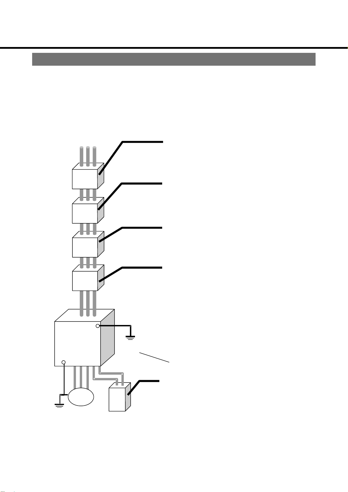
System Configuration and Wiring
Wiring general view
● Wiring must be performed by a qualified electrician.
● To avoid electric shock, do not connect the power supply to the unit.
Inverter
GND
Motor
No-fuse breaker (NFB)
or earth leakage breaker
Used to protect the power line.
Interrupts the circuit in the case of excessive
current.
Note: Use a high frequency proof earth leakage
breaker for the inverter.
Noise filter (NF)
Blocks noise from the power line.
Also reduces effect of noise from the inverter.
Magnetic contactor (MC)
Turn main power to inverter on/off.
Used with surge absorber mounted.
Note: Never attempt to start or stop the motor with
the electromagnetic contactor.
AC reactor (AC-L)
Reduces harmonic current of the power source.
Be sure to connect GND wire to the earth
to avoid electric shock.
Regenerative resistor
Improves regenerative braking capability.
Only for the inverter incorporating the
regenerative braking circuit and resistor
- 12 -
Page 13

)
)
)
)
)
)
)
Inverter and applicable peripheral equipment
Wiring apparatus selection
(1) Selection of no-fuse breaker, magnetic contactor, thermal relay, and wiring
Inverter No.
M2X044***
M2X084***
M2X154***
M2X224***
M2X374***
M2X554***
M2X754***
The cables connected to the ground terminal must be the same size as the power
supply cable and the motor cable, respectively.
(2) Relay selection
For relays used in control circuits such as the control input terminal, you should use a
small signal relay (min. guaranteed current of 1mA or less) in order to prevent poor
contact.
Applicable
motor
(kW)
0.4
0.75
1.5
2.2
3.7
5.5
7.5
No-fuse breaker
(Rated current)
Matsushita Electric Works
BBC35N
(5A)
BBC35N
(5A)
BBC310N
(10A)
BBC315N
(15A)
BBC320N
(20A)
BBC320N
(20A)
BBC330N
(30A)
Magnetic
contactor
(Contact configuration)
Matsushita Electric Works
BMFT61044N
(3P+1a)
BMFT61044N
(3P+1a)
BMFT61044N
(3P+1a)
BMFT61044N
(3P+1a)
BMFT61044N
(3P+1a)
BMFT61044N
(3P+1a)
BMFT61044N
(3P+1a)
Thermal
∗
relay
(Current adjustment range)
Matsushita Electric Works
BMF903E
(1.4 - 2.2A)
BMF904E
(1.7 - 2.6A)
BMF907E
(2.8 - 4.2A)
BMF911E
(4.0 - 6.0A)
BMF915E
(5.0 - 8.0A)
BMF927E
(9.0 - 13.0A)
BMF937E
(12 - 18A)
∗
2
Output
Control
circuit
0.75
(AWG18)
0.75
(AWG18)
0.75
(AWG18)
0.75
(AWG18)
0.75
(AWG18)
0.75
(AWG18)
0.75
(AWG18)
1
Input
(for power
supply)
2.0
(AWG14)
2.0
(AWG14)
2.0
(AWG14)
2.0
(AWG14)
2.0
(AWG14)
3.5
(AWG12)
3.5
(AWG12)
Wiring (mm2)
(for motor)
2.0
(AWG14
2.0
(AWG14
2.0
(AWG14
2.0
(AWG14
2.0
(AWG14
2.0
(AWG14
3.5
(
AWG12
<Examples> Matsushita Electric Works: DS type, NK type, HC type
Omron: G2A type
(3) Control circuit switch selection
If using a switch instead of a relay, use a switch for extremely small current in order to
prevent poor contact.
<Example> Nihon Kaiheiki: M-2012J-G
∗1 To use the inverter for parallel operation, select the thermal relay according to the motor used.
∗2 The above motor cable sizes apply to the case where the distance between the motor and the inverter is
20 m or less. If the distance between the motor and the inverter exceeds 20 m, select a cable size of
the next higher rank.
- 13 -
Page 14

System Configuration and Wiring
Wiring
Standard wiring diagram
・・・・0000.4kW,0
3-phase power supply
AC380~460V
50/60Hz
External frequency setting
potentiometer
1/4 W, 5 kΩ, B curve
CCW/stop switch
CW/stop switch
Frequency setting selection (1)
Frequency setting selection (2)
Free-run
Trip reset
Control ground
Note 1) When the “PLC” and “12 V” terminals are short-circuited, sink input is available.
4kW,0.75kW,1
4kW,04kW,0
Frequency meter
1 mA (full scale)
Terminate the shielded cables
properly.
75kW,1.5kW,2
75kW,175kW,1
NFB
③
①
Note 1) Short-circuit bar
5kW,2.2kW,3
5kW,25kW,2
R/L1
S/L2
T/L3
5V
②
FIN1
G
FOUT
FIN2
12V
PLC
I1
I2
I3
I4
I5
I6
G
3.3kΩ
2kW,3.7kW
2kW,32kW,3
Main circuit
Control circuit
▽
▽
▽
△
▽
△
▽
△
▽
△
▽
△
▽
△
(Frame ground)
E E
Be sure to connect the ground terminal. (Ground resistance:
10Ω or less, φ1.6 mm or more)
7kW
7kW7kW
U/T1
V/T2
W/T3
O1
(Collector) Trip output
(Collector) Arrival signal
O2
(Emitter)
COM1
NC
COM2
NO
CE
V
C
max.=50mA
I
Trip signal contact
capacity
DC30V 2A
AC30V 2A
Motor
IM
Ground terminal
max.=DC24V
When the “PLC” and “G” terminals are short-circuited, source input is available.
For details on sink input and source input, see P16.
- 14 -
Page 15

Wiring
・5
・5.5kW,7
5kW,7.5kW
・5・5
5kW,75kW,7
5kW
5kW5kW
3-phase power supply
AC380~460V
50/60Hz
External frequency setting
potentiometer
1/4 W, 5 kΩ, B curve
Frequency meter
1 mA (full scale)
Run/stop switch
CCW/CW switch
Frequency setting selection (1)
Frequency setting selection (2)
Free-run
Trip reset
Control ground
Note 2)
Regenerative
braking resistor
NFB
③
①
Note 1) Short-circuit bar
connection terminal
②
R/L1
S/L2
T/L3
5V
FIN1
G
FOUT
FIN2
12V
PLC
I1
I2
I3
I4
I5
I6
G
P PB
3.3kΩ
R
Main circuit
Control circuit
▽
△
▽
△
▽
△
▽
△
▽
△
▽
△
U/T1
V/T2
W/T3
O1
▽
▽
(Collector) Trip output
O2
(Collector) Arrival signal
COM1
(Emitter)
V
CE
max.=DC24V
I
C
max.=50mA
NC
Trip signal contact
capacity
COM2
DC30V 2A
AC30V 2A
NO
Motor
IM
Ground terminal
Terminate the shielded cables
properly.
(Frame ground)
E E
Be sure to connect the ground terminal. (Ground resistance:
10Ω or less, φ 1.6 mm or more)
Note 1) When the “PLC” and “12 V” terminals are short-circuited, sink input is available.
When the “PLC” and “G” terminals are short-circuited, source input is available.
For details on sink input and source input, see P16.
Note 2) If you intend to connect an external regenerative braking resistor, specification
check is required. Contact Motor Co., Matsushita Electric Industrial Co., Ltd.
- 15 -
Page 16

o
System Configuration and Wiring
Changing the input signal logic
The inverter provides two types of input signal logics: sink input and source input.
When the “PLC” and “12 V” terminals are short-circuited, sink input is available. When the “PLC”
and “G” terminals are short-circuited, source input is available.
The inverter has been set for sink input before shipment.
The following description is provided on the assumption that the inverter has been set for
sink input.
1) Sink input
This logic indicates that a signal turns ON when a current flows out of an input terminal.
“G” is the common terminal for input signals.
Short-circuit bar
12V
PLC
* The same logic applies to
“I2” through “I6”.
2) Source input
This logic indicates that a signal turns ON when a current flows into an input terminal.
“12 V” is the common terminal for input signals.
Short-circuit bar
G
I 1
G
12V
PLC
G
* The same logic applies t
“I2” through “I6”.
I1
- 16 -
Page 17

2
3
Terminal function
(1) Main circuit terminal
0.4kW - 3.7kW 5.5kW - 7.5kW
E R/L1 S/L2 T/L3 U/T1 V/T2 W/T3 E E R/L1 S/L
T/L3 P
U/T1V/T2
PB
/T
E
Capacity Terminal
screw
0.4kW - 7.5kW M4 1.0 - 1.2 All terminals (including “E” terminal)
Tightening torque
N・m
Location
Terminal code Terminal name Function
R, S, T/
L1, L2, L3
U, V, W/
T1, T2, T3
E
P
PB PB terminal
∗1: Only for 5.5 kW and 7.5 kW.
Power supply
terminal
Motor terminal Connected to a 3-phase induction motor.
Ground
terminal
P terminal Converter’s + terminal
Connected to a commercial power supply (3-phase 380 to 460 V,
50/60 Hz).
Inverter’s frame ground (FG) terminal. Ground resistance: 10 Ω or
less
Regenerative resistor connection terminal
Connect a regenerative resistor between the P and PB terminals.
∗1
- 17 -
Page 18

System Configuration and Wiring
(2) Control terminal
Relay contact output terminal
<
COM2 NC NO
Terminal code
5V
12V
FIN1
FIN2
G
FOUT
Terminal name Function
terminal for frequency
External power
supply terminal
Input terminal for
frequency setting
Control ground
Frequency meter
Power supply
setting
terminal
O1 O2 FIN2 FIN1 FOUT IIII2 IIII4 IIII6 12V
>
COM1 12V PLC G IIII1 IIII3 IIII5 G 5V
Short-circuit bar
Only fossr the inverter with
*
communication interface.
Terminal screw size: M2.5, Tightening torque: 0.3 to 0.5 N•m
+5 VDC is applied. Imax = 20 mA
+12 VDC is applied. Imax = 20 mA
Serves as a common terminal for contact inputs when the source input
logic is selected.
When the source input logic is selected (the PLC and G terminals are
short-circuited), short-circuiting each input terminal and this terminal turns
ON the input signal. Opening these terminals turns it OFF.
Frequency setting is enabled by applying 0 to +5 VDC (or 0 to +10 VDC)
between the FIN1 and G terminals, or by applying 4 to 20 mA between
the FIN2 and G terminals.
If both the FIN1 and FIN2 inputs are activated, a larger frequency setting
is enabled.
To use these terminals, change [ Frequency command selection] to
-
“
Input impedance FIN1: 100 kΩ
FIN2: 250 Ω
Common ground terminal for contact inputs.
Serves as a common terminal for contact inputs when the sink input logic is
selected.
When the sink input logic is selected (the PLC and 12V terminals are
short-circuited), short-circuiting each input terminal and this terminal turns
ON the input signal. Opening these terminals turns it OFF.
Outputs a voltage proportional to the output frequency between the
FOUT and G terminals. Connect a DC ammeter with 1 mA full-scale.
By changing [ FOUT switching], a pulse output synchronized with the
output frequency is enabled.
” or “
-
”.
DSW1*
CN4*
- 18 -
Page 19

Terminal code
IIII1
IIII2
IIII3
IIII4
Input terminals
IIII5
IIII6
G
O1
O2
COM1
Output terminals
NC
NO
COM2
*
CN4
*
DSW1
Terminal name Function
CCW/stop
command terminal
CW/stop command
terminal
Frequency setting
selection terminal
Control ground Common ground terminal for contact inputs.
Output signal
terminal
Output signal
terminal
RS485
communication
connector
Terminating
resistance
Short-circuiting the “I1” and “G” terminals activates the CCW command.
Opening these terminals activates the stop command.
Short-circuiting the “I2” and “G” terminals activates the CW command.
Opening these terminals activates the stop command.
When [ I1・I2 function selection] is changed, “I1” serves as run/stop
command, and “I2” serves as CCW/CW command.
By using [ Operation mode selection], [ I5 function selection] and
[ I6 function selection], you can select the following functions:
Operation mode
2-speed operation mode
4-speed operation mode
8-speed operation mode
16-speed operation mode
Open-collector output terminals. (Signal is not retained when power is OFF.)
By using [ Output signal ① selection] and [ Output signal ②
selection], you can select the signal type. The default settings of “O1” and
“O2” are trip signal (transistor turns ON at trip), and arrival signal (transistor
turns ON at arrival), respectively.
“O1” “O2” (collector) Ic max. = 50 mA
“COM1” (emitter) Vce max. = 24 VDC
Relay contact output terminals. (Signal is not retained when power is OFF.)
By using [ Relay output signal selection], you can select the signal
type.
When inactivated: NO - COM2 open, NC - COM2 closed
When activated: NO - COM2 closed, NC - COM2 open
Contact capacity: 30 VAC 2 A, 30 VDC 2A
Contact rating: Contact resistance 50 mΩ or less (via 5 VDC 1A voltage drop
method)
RS485 communication connector
(6-pin modular jack RJ11)
Terminating resistance selection switch
The 390Ω resistance ON/OFF can be selected.
OFF: ON:
Pin No.
1 Unused
2 +5V
3 RS485+
4 RS485-
5 G (Control ground)
6 Unused
IIII3
CCW jogging CW jogging
IIII4
Frequency setting selection
Function
IIII5
Selectable from Free-run stop, External
forced trip, No. 2 acceleration/ deceleration
time and Trip reset commands.
Pin 6
IIII6
Pin 1
* Only for the inverter with communication interface
- 19 -
Page 20

System Configuration and Wiring
Precautions when wiring
Internal circuits retain high voltage for a certain period time after power is off. Wait at least for
15 minutes after power off before starting any wiring.
Main circuit
(1) If the power supply terminals (R/L1, S/L2 and T/L3) and motor terminals (U/T1,
V/T2 and W/T3) are connected in reverse, the inverter will be damaged. Be
sure not to connect these terminals in reverse.
(2) Do not ground the main circuit terminal.
(3) Do not short-circuit the motor terminals (U/T1, V/T2 and W/T3).
(4) The ground (E) terminal is the inverter’s frame ground terminal.
(5) To connect the main circuit terminal, be sure to use a crimp terminal with
insulation sheath.
(6) To run the inverter, use the no-fuse breaker (NFB) according to the standard
connection diagram.
Select a no-fuse breaker according to the motor ratings.
(7) Be sure to remove the phase advancing capacitor from an existing motor.
Control circuit
(1) When connecting a control circuit conductor, strip off a suitable length of insulation: too
long bare conductor will touch with another conductor; too short bare conductor will
easily pull off the connection. When connecting two more conductors together, twist
them before wiring or connecting.
(2) When using a bar terminal or solid conductor, select one having a diameter equal to 0.9
mm or less. Fastening screw may be damaged.
(3) Do not apply more than 24 VDC, 50 mA to the output terminals (COM1, O1, O2), or
apply voltage to terminal in reverse.
Do not apply 30 VAC, 2 A (or 30 VDC, 2 A) to the output terminals (COM2, NO and NC).
(4) Do not apply an external voltage to the input terminals (I1 to I6).
(5) Do not short-circuit the frequency setting power supply terminal (5 V) and the external
power supply terminal (12 V) with the control ground (G) terminal.
(6) To directly drive the relay by the output terminals (COM1, O1, O2), mount a flywheel diode
(FD).
5.5㎜±1㎜
COM1
01/02
FD(100V
1A)
R Y
<Examples> Fuji Electric ERA15-01
Pay attention to polarity of diode.
(7) For connections to the control circuit, use twisted cables or shielded cables.
(8) The cable connected to the control circuit must be placed apart from a power cable.
(9) To tighten a cable, put a screwdriver on the terminal perpendicularly.
ERB12-01
- 20 -
Page 21

y
asonic
asonic
Parameter Setting
Setting
Operation Panel
2-digit LED
Pan
Pan
r/min
Hz
A
V
*
5-digit LED
DATA
SET
RUN
MODE
^
^
STOP
* Normally in the monitor mode, the operation panel displays frequency (Hz).
* The indicated value is just for reference. Do not use this device as a measuring instrument.
Also, the operation panel can display the magnification factor specified by [ Display scale
factor].
5-digit LED
2-digit LED
MODE switch
DATA SET switch
Displays an output frequency, set frequency, value magnified by the scale factor,
cause of error and parameter value.
Display a parameter number. In the monitor mode, the direction of motor rotation
is displa
Used to change the monitor mode. Pressing this switch changes the monitor as
follows:
Used to switch between the parameter No. mode and the parameter value mode,
and to register a parameter value.
ed.
Output frequency Converter voltage Motor current
Description on each mode
●
Monitor mode
Parameter No.
mode
Parameter
value mode
Displays an output frequency, converter voltage and motor current.
At power-ON, the operation panel is set to this mode.
If the MODE switch is pressed in the parameter No. mode or
parameter value mode, the display will be changed to this mode.
A parameter number (
is pressed in the monitor mode, the display will be changed to this
mode.
A parameter set value blinks. The set value can be changed with
the △ or ▽ button.
Pressing the DATA SET switch after changing a set value
registers the updated value. Even if the MODE switch is
pressed, the data will not be registered.
- )) blinks. If the DATA SET switch
△ ▽ switch
RUN switch
STOP switch
Use to select, set and modify a parameter.
Can be held down for continuous changing.
Issues the run command.
Issues the stop command.
- 21 -
Page 22

r
r
Parameter Setting
Power ON
Monitor mode
Output frequency
MODE
Output current
r/min
Hz
A
MODE
△
▽
Direct speed setting of No.0.
MODE
DATA SET
MODE
Converter voltage
V
Use △ and ▽ .
Note: When [ Speed
setting selection] is
● Parameter LED will blink
Parameter
No. mode
△
▽
△
▽
MODE
mode
DATA SET
Storage To monitor
DATA SET
Parameter value
mode
Pressing DATA SET switch in the
parameter value mode stores the data.
If MODE switch, the data will be
saved upon power off.
Select the desired paramete
No. using △ and ▽ .
● Parameter LED will blink
△
▽
Select the desired paramete
No. using △ and ▽ .
△
▽
- 22 -
Page 23

Test Operation
Pre-operation inspections
After installing and wiring, inspect the following before running the inverter.
(1) Check if wiring is correct. (In particular, check improper connections of the power
supply terminals (R/L1, S/L2 and T/L3) and motor terminals (U/T1, V/T2 and W/T3),
short-circuited load and ground fault.)
(2) Does input power comply with the rating?
(3) Are there any places that could be shorted by wire cuttings, etc?
(4) Are any screws or terminals loose?
Test run
(1) Preparation for safety operation
① Set the motor so that it can be independently operated.
② Turn off all the inputs on the control terminal block.
(2) Follow the test procedure:
Step
①
Power ON
Operation panel
Switch Display on LED
Remarks
•
Monitor mode upon power-up
(Output frequency display)
②
Frequency
setting
(See Note)
③
Return back
to the monitor
mode
④
Run (forward)
command
⑤
Stop
command
Press △ .
Press △ to
specify frequency.
Press
register data.
MODE
Press RUN .
to
Press STOP .
•
The 0th speed frequency is
displayed. (The set value is “0.00”
Hz.)
•
Set the 0th speed frequency to
“60” Hz.
•
Frequency gradually changes.
•
The direction of motor rotation is
displayed.
•
Frequency gradually changes to
“0” Hz.
<Operation check>
① Smooth motor rotation. No unusual sound. No excessive vibration.
② Smooth acceleration and deceleration.
③ Motor direction and speed.
Note) To specify frequency with the inverter’s control dial, set [ Frequency command selection] to
(Inverter’s control dial).
- 23 -
Page 24

(
)
(
)
(
)
y
Operation Function
Selection of the run command
The M2X series inverter provides the following six types of operations depending on
whether frequency commands and run commands are entered through the operation panel
or the terminal block.
Speed command
From
operation
panel, or
control dial
Terminal block
FIN1 or FIN2 on
terminal block
∗
2
Run command Parameter
Operation
panel
Terminal
block
Frequency command
selection
1 ○ ○ ∗1 ○ ∗1 or
2 ○ ○ ∗1 ○ ∗1 or
3 ○ ○ or
4 ○ ○ or
5 ○ ○ or
6 ○ ○ or
Run command
selection
both)
(both
panel
panel
(terminal block)
(terminal block)
Default settings of [ Frequency command selection] and [ Run command selection] are and
, respectively.
Frequency command selection changing procedure
Example) Change [ Frequency command selection] from to .
Step
① Power ON
② Parameter
number mode
③ Parameter set
value mode
Switch LED displa
Press DATA SET
Using △ , select the
parameter No.
Press DATA SET
Using △ , select the
parameter value
Press DATA SET to
save the value
Operation panel
∗1 The run command from the terminal block overrides the command from the operation panel, if both
are enabled.
The RUN switch on the operation panel is active only when both the CCW/stop switch (I1) and the
CW/stop switch (I2) on the terminal block are OFF. If both or one of [I1] and [I2] are turned on while
the RUN switch is active, the operation mode set from RUN switch is cancelled.
∗2 The “FIN1” and “FIN2” terminals are intended for voltage command (0 to 5 VDC or 0 to 10 VDC) and
current command (4 to 20 mADC), respectively. For details, refer to “Terminal function: “(2) Control
Terminal” on P18.
- 24 -
Page 25

y
Acceleration/deceleration time changing procedure
Example) Change [ Acceleration time] from
.
to
.
Step
①
Power ON
②
Parameter
number mode
③
Parameter set
value mode
Switch
Press DATA SET .
Using △ , select the
parameter No.
Press DATA SET .
Using △ , select the
parameter value.
Press DATA SET to
save the value.
Operation panel
.
.
LED displa
∗1
∗
1
∗1 To change deceleration time, use [ Deceleration time].
- 25 -
Page 26

Operation Function
Operation function
The inverter has the following control functions that are made active from the operation
panel and terminal block.
Operation control
Jogging
Free-run stop
DC brake
Positioning DC
brake
Acceleration/deceleration time is set to “0”. This function is optimum for
positioning. By setting [ Operation mode selection] to “2-speed mode”,
jogging operation is enabled.
When the “I3” and “G” control input terminals are short-circuited, CCW
jogging is enabled. When “I4” and “G” are short-circuited, CW jogging is
enabled, and the jogging frequency is output.
You can switch over between the normal operation mode and the jogging
mode.
The jogging frequency can be specified in the range of 0 to 30 Hz. If the
jogging frequency is too high, the inverter may trip due to overcurrent.
Turns off the output voltage applied to the motor, allowing the motor to coast.
This function is useful to brake the motor mechanically. Remember that
touching the motor output terminals (U/T1, V/T2 and W/T3) may cause
electric shock even if the free-run stop function is activated.
Activates the brake by applying a direct current to the motor at the time
when the inverter shifts from the running status to the stop status. If the
CCW, CW or jogging command is issued while the DC brake function is
activated, the DC brake is disabled, and the motor starts running as
specified by the command.
When a stop command is issued during normal operation, the motor
soft-stops, and the DC brake is activated when the output frequency is
reduced to 3 Hz. (The frequency at which the brake is activated can be
changed with the parameter).
Description
DC brake for
full-range stop
When the frequency is set to “0”, the DC brake is activated when the output
frequency falls below 1 Hz.
The DC brake intensity (torque) and time can be specified with the
parameters.
When a stop command is issued during normal operation, the DC brake is
immediately activated without soft-stop.
The DC brake intensity (torque) and time can be specified with the
parameters.
The DC brake time is twice as long as the time specified for “Positioning DC
brake”.
- 26 -
Page 27

<Examples of DC Brake Operation Patterns>
Run
command
Positioning DC brake
Preset deceleration time
Time specified by [ DC brake time]
Frequency specified by [ Brake start frequency]
Output
frequency
Time determined by GD2 and
torque of the load, and [
DC brake intensity]
Motor speed
vs brake
Regenerative
braking
DC brake
DC brake for full-range stop
Run
command
Time specified by [ DC brake time]
Output
frequency
Motor speed
vs brake
DC brake
Time determined by GD2 and
torque of the load, and
[ DC brake intensity]
- 27 -
Page 28

Operation Function
Run mode
The inverter operates in the following two run modes.
Select the desired mode in the parameter [ Run mode selection].
Function of terminal block
Mode
IIII1 IIII2 IIII3 IIII4 IIII5
2-speed
4-speed CCW CW
CCW CW
CCW
jogging
Frequency setting
CW
jogging
selection
Free-run stop
External forced trip
command
No.2 acceleration/
deceleration time
selection
Trip reset command
Free-run stop
External forced trip
command
No.2 acceleration/
deceleration time
selection
Trip reset command
∗
1
IIII6∗1
Free-run stop
External forced trip
command
No.2 acceleration/
deceleration time
selection
Trip reset command
Free-run stop
External forced trip
command
No.2 acceleration/
deceleration time
selection
Trip reset command
Setting in
[ Run
mode
selection].
[Default setting]
Free-run stop
8-speed
CCW CW Frequency setting selection
External forced trip
command
No.2 acceleration/
deceleration time
selection
Trip reset command
16-speed
CCW CW Frequency setting selection
In the 4-, 8- or 16-speed mode, the following multi-speed operation is enabled by short-circuiting or
opening the frequency setting selection terminals. When all the terminals are opened, the 0th speed
frequency is selected, allowing you to specify frequency with the [ Set frequency (0th speed)]
parameter, external frequency setting control dial, or the inverter’s control dial.
With [ Frequency command selection], select whether to use the 0th speed frequency, external
frequency setting control dial or the inverter’s control dial.
■ Input terminal description
(1) Input terminals are given the following priority.
DC brake < Normal operation < Jogging < Free-run stop < External forced trip
Example)
① If the run command is issued while the DC brake is activated, the motor
will immediately start running.
② If the free-run stop command is issued during jogging operation, the
motor will coast to stop.
③ Even if the run command is issued while the free-run command is
activated, the motor will not start running.
(2) If both the CCW and CW commands are issued during trip, the trip can be
canceled. Before canceling the trip, remove the cause of the trip.
∗1 [ I5 function selection], [ I6 function selection]
- 28 -
Page 29

■ Frequency setting selection method for multi-speed operation
(1) When [ Multi-speed input selection] is set to (1 BIT): 1-bit
input
One type of multi-speed frequency can be assigned to one of the [Frequency
setting selection] terminals. When the 4-speed, 8-speed and 16-speed
operation modes are selected, up to 3-stepped, 4-stepped and 5-stepped
speed operations are enabled, respectively.
Example: 16-speed mode
Control terminal number
IIII3 IIII4 IIII5 IIII6
OFF OFF OFF OFF
ON × × ×
OFF ON × ×
OFF OFF ON ×
OFF OFF OFF ON
• “ON” and “OFF” indicate the connection between each frequency setting selection
terminal and the “G” terminal.
• “x” indicates that either “ON” or “OFF” is acceptable.
(2) When [ Multi-speed input selection] is set to
input [Default setting]
You can select frequency by setting a binary number for the frequency setting
selection terminals.
< 4-speed mode >
IIII3 IIII4
OFF OFF
ON OFF
OFF ON
ON ON
Frequency setting
0th speed frequency
1st speed frequency
2nd speed frequency
3rd speed frequency
Frequency setting
0th speed frequency
1st speed frequency
2nd speed frequency
3rd speed frequency
4th speed frequency
(Binary): Binary
<
8-speed mode
IIII3 IIII4 IIII5
OFF OFF OFF
ON OFF OFF
OFF ON OFF
ON ON OFF
OFF OFF ON
ON OFF ON
OFF ON ON
ON ON ON
>
Frequency setting
0th speed frequency
1st speed frequency
2nd speed frequency
3rd speed frequency
4th speed frequency
5th speed frequency
6th speed frequency
7th speed frequency
- 29 -
Page 30

Operation Function
< 16-speed mode >
Control terminal number
IIII3 IIII4 IIII5 IIII6
OFF OFF OFF OFF
ON OFF OFF OFF
OFF ON OFF OFF
ON ON OFF OFF
OFF OFF ON OFF
ON OFF ON OFF
OFF ON ON OFF
ON ON ON OFF
OFF OFF OFF ON
ON OFF OFF ON
OFF ON OFF ON
ON ON OFF ON
OFF OFF ON ON
ON OFF ON ON
OFF ON ON ON
ON ON ON ON
Frequency setting
0th speed frequency
1st speed frequency
2nd speed frequency
3rd speed frequency
4th speed frequency
5th speed frequency
6th speed frequency
7th speed frequency
8th speed frequency
9th speed frequency
10th speed frequency
11th speed frequency
12th speed frequency
13th speed frequency
14th speed frequency
15th speed frequency
• “ON” and “OFF” indicate the connection between each frequency setting
selection terminal and the “G” terminal.
- 30 -
Page 31

p
p
p
■ Operation pattern in 2-speed mode - Example:
When [ I5 function selection] is set to - (No. 2 acceleration/deceleration
time)
When [ I6 function selection] is set to (External forced trip)
CCW
CW
CCW/stop switch
(I1)
CW/stop switch
(I2)
CCW jogging
(I3)
CW jogging
(I4)
No. 2 acceleration/deceleration time
(I5)
External forced trip
(I6)
Acceleration time
0th speed
Deceleration
time
Positioning DC brake
0th
No. 2
eed
s
deceleration time
Jogging frequency
Positioning DC brake
■ Operation pattern in 4-speed mode - Example:
Acceleration time
Free-run stop
(trip)
0th speed
When [ I5 function selection] is set to (Free-run command)
When [ I6 function selection] is set to - (No. 2 acceleration/deceleration
time)
Acceleration time
2nd speed
CCW/stop switch
Frequency setting selection (1)
Frequency setting selection (2)
No. 2 acceleration/deceleration time
(I1)
CW/stop switch
(I2)
(I3)
(I4)
Free-run
(I5)
(I6)
CCW
CW
0th speed
Deceleration
time
Positioning DC brake
0th
s
eed
No. 2
deceleration
time
1st speed
Deceleration time
No. 2 acceleration time
3rd
s
eed
Free-run stop
- 31 -
Page 32

p
Operation Function
■ Operation pattern in 4-speed mode - Example:
When both [ I5 function selection] and [ I6 function selection] are set to
-
(No. 2 acceleration/deceleration time)
CCW
CW
CCW/stop switch
(I1)
CW/stop switch
(I2)
Frequency setting selection (1)
(I3)
Frequency setting selection (2)
(I4)
No. 2 acceleration/deceleration time
(I5)
No. 2 acceleration/deceleration time
(I6)
Acceleration time
0th speed
Positioning DC brake
Deceleration
time
No. 2 acceleration time
0th
eed
s
No. 4 acceleration time
1st speed
No. 3
acceleration
time
No. 2
deceleration
time
No. 4 deceleration time
2nd speed
- 32 -
Page 33

Protective Function
Protective functions
Your inverter is equipped with the following protective function that:
① displays warning message, or
② avoids trip without displaying warning message.
③ displays warning message and turns off inverter output, or
④ trips the inverter (the trip signal will be removed upon power off)
Display on
Type
①
②
③
5-digit LED
Electronic
thermal trip
Monitor
(
Flashes
Overcurrent stall
prevention
(Not displayed)
Overvoltage
stall prevention
(Not displayed)
Undervoltage
Instantaneous
power failure
protection
)
CW rotation
prevention
Monitor display flashes when the
∗
3
output current reaches the
electronic thermal trip level and
the timer operates.
If the output current exceeds [
Current limit operating point] during
acceleration or constant-speed
operation, the output frequency is
reduced for trip prevention.
(The operation level can be
adjusted with [ Current limit
operating point].)
If the converter’s DC voltage
exceeds approx. 775 V during
deceleration, the deceleration time
is prolonged for trip prevention.
(The deceleration time can be
adjusted with [ Deceleration
factor at stall].)
When the converter’s DC voltage
falls below approx. 360 V, it is
judged as “instantaneous power
failure”, and the inverter’s output is
turned off.
DC voltage falls below approx.
300 V, the control circuit is reset.
If the voltage is restored by the
time the control circuit is reset, the
operation can be continued.
When the CW rotation prevention
function is selected, CW rotation is
prevented when the CW signal is
issued.
Protective function
∗1
When the converter’s
Check for overloading and reduce
the load as necessary.
Increase the acceleration time, or
reduce the inertial load.
Prolong the deceleration time, or
reduce the inertial load.
Check the power source, cabling,
wiring, etc.
∗2
Check if the CW command is not
issued.
Corrective action
∗1 The inverter can continue normal operation with approx. 15 ms power interruption.
∗2 Enabled when [
∗3 This function is enabled only when [
- -
Restart prevention upon power recovery] is set to .
CW rotation prevention] is set to .
33
Page 34

Protective Function
Type
③
④
Display on
5-digit LED
Restart
prevention
when
power is
restored
Overcurrent trip
(at constant speed)
-
Protection by CT
detection
(During acceleration)
-
(During deceleration)
Regenerative
overvoltage trip
Overvoltage trip
retry at
power-ON
Overload trip
(electronic
thermal)
∗2
-
Protective function Corrective action
Prevents the inverter from
restarting automatically if already
given the run command before
power is recovered or turned up or
it is reset.
When the inverter’s output current
exceeds approx. 200% of its rated
current, the inverter trips. (The
displayed message varies
depending on the inverter’s
operating condition.)
When the converter’s DC voltage
exceeds approx. 800 V, the inverter
trips.
When overvoltage trip occurs
because of too large inductance of
the power factor improving AC
reactor in the inverter’s input circuit,
output is turned off.
When the converter’s DC voltage
falls below approx. 800 V, the trip
is automatically canceled,
enabling normal operation.
If the motor current continues to
exceed the level set in [Electronic
thermal], the inverter will be
tripped because it may be
overloaded.
is displayed, and the
∗1
Issue the stop command once,
and then issue the run command.
Power supply voltage drop,
excessive GD
acceleration/deceleration time,
short-circuited load or ground fault
may be considered as the cause
of the trip. Examine the cause of
trip thoroughly.
If trip occurs while the inverter is
running, the deceleration time may
be too short and should be
extended. In some cases, an
external regenerative resistor may
be required. If the trip occurs
upon power-up, the inductance of
the power factor improving AC
reactor at the input of inverter may
be too large, use an AC reactor
compatible with the capacity of the
inverter.
The power factor improving AC
reactor’ capacity may be too large.
Select a proper rector according to
the inverter’s capacity.
Reduce the load, change
operating pattern or use larger
size inverter.
2
of load, insufficient
∗1 This function is enabled only when [
∗2 When [
inverter from restarting automatically.
Restart prevention when power is restored] is set to , this function prevents the
- -
Overvoltage trip retry at power-ON] is set to .
34
Page 35

Type
Display on
5-digit LED
Radiator fin
overheat
protection
CPU error
When the temperature of the
radiator fin exceeds approx.
100℃, the temperature sensor is
activated to trip the inverter.
Trips the inverter if the
micro-computer causes an error.
Protective function
Examine the cooling fan and the
ambient temperature.
The microcomputer operation may
be interfered by external noise.
Locate and remove the noise
source or reduce the noise level.
Corrective action
④
Self-diagnosis
trip
Communication
error
External forced
trip
Trips upon changing in certain
parameter, e.g. [ Operation
mode selection].
If communication is interrupted for
a period of, or longer than [
Protocol timeout] as many times
as, or more frequently than [
Communication retry frequency], it
is judged as communication error.
Trips the inverter when [ I5
function selection] or [ I6
function selection] is set to
external forced trip and I5/I6 is not
connected to [G].
After short-circuiting “I5/I6” and
“G”, reset the trip.
This is not an error. After trip is
canceled, the updated result will
become effective.
Check the communication host for
abnormal condition.
After short-circuiting the “I5” or “I6”
terminal and the “G” terminal,
cancel the trip.
When a thermal protector is
connected, examine the cause of
overload.
Note) If the LED display shows a cause of trip and “ ” alternately after
the trip is reset, the cuase of trip has not been removed yet. Remove the
cause of trip first, and then reset the trip again.
Note) The cooling fan driving sequence is shown below.
Power supply
Run command
Fan
2 min. 2 min.
ON
OFF
Running
Halted
Driven
Halted
While the inverter trips, the fan is driven only for two minutes.
- -
35
Page 36

Protective Function
Canceling trip
First remove the cause and then reset the system by following one of the following steps.
[1] Turn off the inverter. Wait until the trip message disappears and then power
on again.
[2] Leaving the trip message displayed, connect both [I1] and [I2] to [G] for at
least 0.1 seconds. ∗1
[3] Leaving the trip message displayed, press both △ and ▽ switches
on the operation panel for at least 1 second.
[4] Leaving the trip message displayed, issue the trip reset command.∗2
* If the CPU error
procedure. The trip cannot be canceled with the above [2], [3] and [4] methods.
occurs, cancel the trip according to the above
∗1
When [
canceled.
∗2
This method is effective only when [ I5 function selection] or [ I6 function selection] are set
to
- -
I1/I2 function selection] is set to “I1: Run/stop” and “I2: CCW/CW”, the trip cannot be
.
36
Page 37

Maintenance/Inspection
You should perform maintenance/inspection on a regular basis in order to ensure safety
and keep the inverter in good running order.
Precautions when performing maintenance/inspections
(1) The power should be turned on/off only by the person performing the task.
(2) The internal circuits of the inverter remain charged with high voltage for a short
while after power is turned off. To perform inspection, first turn off the power and
then wait for the LED display on the operation panel to go off (min. 15 minutes).
(3) Do not use a megger for the purpose of measuring insulation resistance.
Otherwise, the inverter is damaged.
Inspection items and environment
●
Ordinary/normal usage conditions
Ambient conditions: Annual mean temperature 30°C, max. 20 hrs/day at max. load rate 80%
●
Perform daily and periodic inspections in accordance with the following items:
Classification Inspection cycle Inspection items
・Ambient temperature, humidity, dirt, dust, foreign objects, etc.
・Is there abnormal vibration/noise?
・Is main circuit voltage normal?
・Is there strange odor?
Daily inspection Daily
Periodic
inspections
Caution>
<
1 year
・Is there lint in the air holes?
・Cleanliness of control unit
・Is wiring damaged?
・Are equipment connections loose or off center?
・Are foreign objects lodged in at the load side?
・Are fastened sections loose?
・Is there evidence of overheating?
・Are terminal blocks damaged?
Inspection cycle for periodic inspections may vary if usage conditions differ from those
given above.
Approximate period for part replacement
Period for part replacement varies depending on how the inverter is used. Parts must
be replaced or repaired when something is wrong with them.
Product
name
Inverter
Part name
Smoothing capacitor Approx. 5 years
Cooling fan
Aluminum electrolytic
capacitor on PCB
Standard
replacement period
(hrs)
2 - 3 years (10 - 30
thousand hours)
Approx. 5 years
Remarks
Standard replacement period
gives a number of years for
reference only. If a part becomes
faulty it must be replaced even if
the standard replacement period
has not yet been reached.
- -
37
Page 38

Troubleshooting
Inspection to determine cause of problem
When a problem occurs, perform the inspections and take the measures prescribed in the
following table. If you cannot determine the cause of the problem, if you suspect that the
inverter is not working properly, if a part is damaged, or there are any other problems you
cannot solve, contact your Panasonic dealer.
Problem Possible cause Corrective action
Motor won't run
Motor runs in
wrong direction
Motor runs but
cannot change
speed
Motor runs at
incorrect speed
Unstable motor
speed
Improper wiring
Power is not fed to power input
terminals.
LED on the operation panel is
unlit.
Not a rated voltage on the supply
input terminals.
Error is displayed.
Free-run command is issued.
Both CCW and CW switches are
on.
Check if the frequency setting is
correct.
Motor is locked or overloaded.
One phase is missing.
Check the output terminals (U/T1,
V/T2 and W/T3) for incorrect
phase order.
Motor is overloaded.
No. of phases and voltage of the
motor do not match those of
power source.
Voltage on power input terminal
(R/L1, S/L2 or T/L3) is out of spec.
Check if the frequency setting
range is correct.
Check if the motor’s terminal
voltage is extremely low.
Motor is overloaded.
Load varies excessively.
Correct wiring.
Turn on power.
Turn off and then on power.
Check power supply.
Check the voltage.
See Section [Protective function].
Cancel the command.
Turn off unnecessary one.
Check the frequency setting.
Release the lock or reduce the
load.
Check wiring between the inverter
and motor.
Match the phase order of the output
terminals (U/T1, V/T2 and W/T3)
with those of the motor terminals.
Reduce the load.
Check the specifications and the
identification plate.
Check the voltage.
Check [ Lower limit frequency]
and [ Upper limit frequency].
Check [ Base frequency],
[
Maximum output voltage adjustment]
and [ V/F reduction
characteristic].
Reduce the load.
Keep fluctuations in the load at
minimum. Replace with larger
inverter and motor set.
- -
38
Page 39

,
Parameter Description
No. Parameter name
Set frequency (0th speed)0, 0.5
1st speed frequency 0, 0.5
2nd speed frequency 0, 0.5
3rd speed frequency 0, 0.5
4th speed frequency 0, 0.5
5th speed frequency 0, 0.5
6th speed frequency 0, 0.5
7th speed frequency 0, 0.5
8th speed frequency 0, 0.5
9th speed frequency 0, 0.5
10th speed frequency 0, 0.5
11th speed frequency 0, 0.5
12th speed frequency 0, 0.5
13th speed frequency 0, 0.5
14th speed frequency 0, 0.5
15th speed frequency 0, 0.5
Run command selection
Parameter setting
Adjustment range Min. unit
2
∗
- Upper limit frequency
2
∗
- Upper limit frequency
2
∗
- Upper limit frequency
2
∗
- Upper limit frequency
2
∗
- Upper limit frequency
2
∗
- Upper limit frequency
2
∗
- Upper limit frequency
2
∗
- Upper limit frequency
2
∗
- Upper limit frequency
2
∗
- Upper limit frequency
2
∗
- Upper limit frequency
2
∗
- Upper limit frequency
2
∗
- Upper limit frequency
2
∗
- Upper limit frequency
2
∗
- Upper limit frequency
2
∗
- Upper limit frequency
Operation panel
Factory setting
0.01Hz∗3 0Hz
0.01Hz∗3 50Hz
0.01Hz∗3 30Hz
0.01Hz∗3 15Hz
0.01Hz∗3 0Hz
0.01Hz∗3 0Hz
0.01Hz∗3 0Hz
0.01Hz∗3 0Hz
0.01Hz∗3 0Hz
0.01Hz∗3 0Hz
0.01Hz∗3 0Hz
0.01Hz∗3 0Hz
0.01Hz∗3 0Hz
0.01Hz∗3 0Hz
0.01Hz∗3 0Hz
0.01Hz∗3 0Hz
Check
∗1
Terminal block
Both
Frequency command
selection
RS485 communication
Operation panel
Control dial
- 0 - 5V(4-20mA)
Operation mode
selection
Torque control
- 0 - 10V(4-20mA)
2, 4, 8, 16 speed operation mode
0 - 100 2
Automatic boost
Slip frequency vector control
Jogging frequency
∗
1 Parameters marked by
memorized.
Cancel the trip before use.
∗
2 The lower limit of the adjustment range varies depending on the [
∗
3 When the set value exceeds 160 Hz, the minimum unit of setting is 0.05 Hz.
0
∗2
0.5
in the Check column are tripped for safety if modified or
~30Hz 0.01Hz 7Hz
40
20
4 speed
operation mode
400W -
1.5kW
2.2kW -
7.5kW
Starting frequency] setting.
- -
39
Page 40

(
)
Parameter Description
No.
Acceleration time
No.2 acceleration time
No.3 acceleration time
No.4 acceleration time
DC brake intensity
DC brake time
DC brake selection
Start-up brake time
Brake starting
Carrier frequency
Deceleration time
No.2 deceleration time
No.3 deceleration time
No.4 deceleration time
Base frequency
Maximum output
V/F reduction
characteristic
Parameter name
Adjustment range Min. unit
- 3 sec
0 - 3600 sec
3 sec - 10 sec
10 sec -
0 - 100 2 70
Case of :
0 - 3 sec
Case of - :
0 - 6 sec
Positioning
- Full-range stop
0 - 3 sec 0.05 sec 0
0.5 - 400Hz 0.01Hz∗3 3 Hz
0, 1, 2, 3, 4, 5, 6, 7 5
- 3 sec
0 - 3600 sec
3 sec - 10 sec
10 sec -
30 - 400Hz
0 - 100%
1.0 - 2.0 squared 0.1 1.0
Parameter setting
: in steps of 0.01 sec
: in steps of 0.1 sec
: in steps of 1 sec
: in steps of 0.01 sec
: in steps of 0.1 sec
: in steps of 1 sec
0.05 sec
0.1 sec
1Hz
1%
Factory setting
5 sec
5 sec
5 sec
5 sec
0.5 sec
1.0 sec
Disabled
5 sec
5 sec
5 sec
5 sec
50Hz
100%
Check
∗1
2nd V/F selection
No selection
(Ordinary V/F pattern)
Upper pattern
Lower pattern
2nd V/F base frequency
2nd V/F boost
Jump frequency width
Jump frequency ①
Jump frequency ②
Jump frequency ③
Jump frequency ④
∗
1 Parameters marked by
memorized.
Cancel the trip before use.
∗2 The lower limit of the adjustment range varies depending on the [
∗3 When the set value exceeds 160 Hz, the minimum unit of setting is 0.05 Hz.
in the Check column are tripped for safety if modified or
30 - 400Hz 1Hz 50Hz
0 - 100 2 0
0 - 400Hz 0.01Hz∗3 0Hz
∗2
0, 0.5
0, 0.5
0, 0.5
0, 0.5
- 400Hz 0.01Hz∗3 0Hz
∗2
- 400Hz 0.01Hz∗3 0Hz
∗2
- 400Hz 0.01Hz∗3 0Hz
∗2
- 400Hz 0.01Hz∗3 0Hz
Starting frequency] setting.
- -
40
Page 41

No. Parameter name
I1/I2 function selection
I5 function selection
I6 function selection
Multi-speed input
selection
Parameter setting
Adjustment range Min. unit
I2: Reverse (cw) /stop
I2: Forward (ccw) /Reverse (cw)
External forced trip
Trip reset
Binary
I1: Forward (ccw) /stop
I1: Run/stop
Free-run
- 2nd acceleration/deceleration
1 bit
Factory setting
Check
∗1
Unused
Output signal ①
selection
Output signal ②
selection
Relay output signal
selection
Enabled only when the
relay output terminals
(NC, COM2 and NO)
are used.
Motor current detection
level
Output signal polarity ①
selection
Current limit operating
point
Deceleration factor at
stall
Acceleration mode
selection
Deceleration mode
selection
Running
Free-run
CCW, CW
- Output frequency detection
- Motor current detection
Cause of trip
- DC braking
Running
Free-run
CCW, CW
- Output frequency detection
- Motor current detection
Trip,
Trip, Arrival
50 - 150% 5% 100%
Normal, Reverse
50 - 150% 10% 150%
x1, x2, x4, x8, x16 x8
Linear
Arrival
S curve ①
-
S curve ②
-
∗1 Parameters marked by in the Check column are tripped for safety if modified or
memorized.
Cancel the trip before use.
- -
41
Page 42

Parameter Description
No. Parameter name
Monitor mode
selection
Adjustment range Min. unit
- Set frequency
- Output frequency
Parameter setting
Factory setting
Check
∗1
Display scale factor
Frequency meter adjustment
Frequency meter full-scale
FOUT switching
Comparative frequency A
Comparative frequency B
Agreement detection width
Drop frequency at
instantaneous power failure
Free-run time at instantaneous
power failure
Restart prevention
upon power recovery
- DC voltage
Output current
- Feedback frequency
0.1 - 60.0 0.1 1.0
Current analog output
Digital
Analog
-
0 - 400Hz 1Hz 60Hz
0, 0.5∗2 - 400Hz
0, 0.5∗2 - 400Hz 0.01
0 - 400Hz 0.01
0 - 400Hz 0.01
1, 2, 3, 4, 5 1
Restart
No restart
-
0.01
-
-
∗3
0Hz
Hz
∗3
0Hz
Hz
∗3
3Hz
Hz
∗3
3Hz
Hz
Retry selection
Retry start time
Frequency setting bias
Lower limit frequency
Upper limit frequency
Input filter time constant
Overvoltage trip retry at
power-ON
Trip retry
CW rotation
prevention
No retry
-
Retry up to No. of times set
0 - 120 sec 2 sec 4 sec
0, 0.5
(Lower limit frequency + 0.01) to 400 Hz
0 - − 60Hz 0.01
2
∗
(Upper limit frequency – 0.01) Hz
to
1, 2, 3, 4, 5
No retry
Retry
Enables CW rotation
0.01
0.01
Hz
Hz
Hz
∗3
∗3
∗3
Prevents CW rotation
Electronic thermal
∗
1 Parameters marked by
memorized.
Cancel the trip before use.
∗
2 The lower limit of the adjustment range varies depending on the [
∗
3 When the set value exceeds 160 Hz, the minimum unit of setting is 0.05 Hz.
30 - 150% 5%
in the Check column are tripped for safety if modified or
0Hz
0Hz
60Hz
3
115%
Starting frequency] setting.
- -
42
Page 43

No. Parameter name
Parameter setting
Adjustment range Min. unit
Factory setting
Check
∗1
Trip cause clear
Trip cause①
Trip cause②
Trip cause③
Trip cause④
Trip cause⑤
Parameter initialization
Motor selection
Starting frequency
Automatic voltage
adjustment reference
voltage
Automatic voltage
adjustment selection
-
-
-
-
-
-
-
-
-
-
-
-
-
-
-
0.5 - 10Hz 0.01Hz
∗2
Motor capacity
Number of motor poles
4-pole inverter
capacity
1Hz
∗3
380, 400, 440, 460V 400V
-
-
Enables automatic voltage adjustment
Disables automatic voltage adjustment
Disables automatic voltage adjustment
during deceleration only
Parameter lock
Copy parameter
Motor rated current
Motor no-load current
Motor primary resistance
Slip correction gain
Slip correction response time
∗1 Parameters marked by in the Check column are tripped for safety if modified or memorized.
Cancel the trip before use.
∗2 The motor capacity is defined as follows:
: 3.7 kW, : 5.5 kW, : 7.5 kW.
∗3 The 4-pole motor with the same capacity as the inverter’s rating has been specified as the default
setting.
∗4 The parameter settings marked with asterisk (※) vary depending on the capacity. They will be restored
to the default settings through initialization.
Parameters are not locked
All parameters are locked
Locks unnecessary parameter
Parameters not copied
Parameters are read out to panel
Parameters are written into inverter
Panel data is initialized
0 - 100A 0.01
0 - 100A 0.01
0 – 100Ω 0.01
0, 1, 2, 3, 4, 5, 6, 7
0, 1, 2, 3, 4, 5, 6, 7
: 0.4 kW, : 0.75 kW, : 1.5 kW, : 2.2 kW,
∗4
※
※
※
∗4
∗4
4
0
- -
43
Page 44

Parameter Description
Parameter setting
No. Parameter name
Adjustment range Min. unit
∗1
Factory setting
Check
PID function selection
Proportional (P) gain setting
Integral ( I ) time constant setting
Differential (D) time
constant setting
PID scale ratio setting
Feedback input method
setting
Equipment number
Communication speed 2400, 4800, 9600, 19200bps 9600
Communication
standard
-
-
Disables PID control
Enables PID control (Reverse)
Enables PID control (Normal)
0.2 - 5 0.1 1.0
0.0 - 150.0 sec 0.1 sec 1.0 sec
0.0 - 100.0 sec 0.1 sec 0.0 sec
0.01 -
99.99 0.01 1.0
0 – 5 V input to FIN1
0 – 10 V input to FIN1
4 – 20 mA input to FIN2
80 - 9F 1 81
Bit length: 8, Parity: None, Stop bit: 1
Bit length: 8, Parity: None, Stop bit: 2
Bit length: 8, Parity: Odd, Stop bit: 1
Bit length: 8, Parity: Odd, Stop bit: 2
Bit length: 8, Parity: Even, Stop bit: 1
Bit length: 8, Parity: Even, Stop bit: 2
Bit length: 7, Parity: None, Stop bit: 1
Communication response time
Number of communication retries
Protocol timeout 1 - 255 sec 1 sec 2 sec
Parameter extraction Parameter No.
Bit length: 7, Parity: None, Stop bit: 2
Bit length: 7, Parity: Odd, Stop bit: 1
Bit length: 7, Parity: Odd, Stop bit: 2
Bit length: 7, Parity: Even, Stop bit: 1
Bit length: 7, Parity: Even, Stop bit: 2
5 - 1000ms
0 - 8
1ms 10ms
1
∗
1 Parameters marked by
memorized.
Cancel the trip before use.
- -
in the Check column are tripped for safety if modified or
44
Page 45

Detailed Parameter Description
Function of parameter
No. Parameter name Description
Set frequency
(0th speed)
Used to specify desired operating frequency.
Enabled when [ Frequency command selection] is set to
.
1st speed frequency
2nd speed frequency
3rd speed frequency
4th speed frequency
5th speed frequency
6th speed frequency
7th speed frequency
8th speed frequency
9th speed frequency
10th speed frequency
11th speed frequency
12th speed frequency
13th speed frequency
14th speed frequency
15th speed frequency
Run command
selection
Used to specify frequency for multi-speed operation.
Enabled when [ Operation mode selection] is set to 4-, 8- and 16-speed
operation modes.
Operation
mode
2-speed
mode
4-speed
mode
8-speed
mode
16-speed
mode
I3 I4 I5 I6
CCW
jogging
CW jogging
Frequency setting
selection
Select among:
free-run, external forced trip,
No.2 acceleration/deceleration
and trip reset.
Run command can be selected through the following control facility.
●
●
■
●
(PaNeL) : RUN switch on the operation panel
IIII
(TERminal) : Input terminal [
(BOTH) : Both operation panel and input terminals can
be used.
(SIG) : RS485 communication
1]/[
IIII2]
Frequency command
selection
■: Factory setting
*
When
command.
Used to select whether [ Set frequency (0th speed)], frequency setting input
terminals (FIN1 and FIN2) or the inverter’s control dial is used for the 0th speed
frequency setting.
■
● Analog command
●
● Inverter’s control dial
∗ If
is selected, the input terminal cannot be used for run
[
Set frequency (0th speed)]
FIN1 (Voltage command) 0 to 5 VDC
FIN2 (Current command) 4 to 20 mA
Analog command
FIN1 (Voltage command) 0 to 10 VDC
FIN2 (Current command) 4 to 20 mA
is selected for the inverter that is not equipped with the control
dial, the 0th speed frequency setting is disabled.
- -
45
Page 46

Detailed Parameter Description
No. Parameter name Description
Run mode
selection
Selects the run mode.
●
2-speed mode
Torque control
■
●
●
■
The inverter’s output voltage in
low-frequency range can be
adjusted
* If this parameter setting is
too high, the inverter may trip
due to overcurrent.
4-speed mode
8-speed mode
16-speed mode
-
: Manual torque boost
● :
●
●
:
:
Automatic boost. Performs optimum automatic
torque control for the motor with the same capacity
as the inverter.
Automatic boost. Performs relatively weak
automatic torque control for the motor with the same
capacity as the inverter.
Slip frequency vector control. Performs slip
frequency vector control for the motor selected by
[ Motor selection].
Maximum output voltage
Large
Output voltage
0
Small
Base frequency
Output frequency
Jogging frequency
Acceleration time
■: Factory setting
<Precaution for selecting automatic boost or slip frequency vector control>
・
Select the parameter when the motor is not in operation.
・
Do no use this parameter for parallel operation.
・
Control may become unstable depending on the actual load conditions.
In such a case, set this parameter to “manual torque boost”.
・
When the power supply voltage is high, reduce the inverter’s output
voltage by adjusting [ Base frequency] or [ Maximum output
voltage adjustment].
Used to specify frequency for jogging operation.
Used to determine the output frequency change ratio during acceleration.
・・・・Specify the time required for change by 50 Hz.
・
When this parameter is set to “0” seconds, the actual acceleration time is
0.01 seconds.
・
For a set value less than 3 sec., the increment/decrement step is 0.01
sec. For a set value over 3 sec. to less than 10 sec., the step is 0.1
sec. For a set value over 10 sec., the step is 1 sec.
- -
46
Page 47

0
No. Parameter name Description
No.2 acceleration
time
No.3 acceleration
time
No.4 acceleration
time
DC brake
intensity
DC brake time
DC brake
selection
Start-up brake
time
Brake starting
frequency
Carrier frequency Select eight of the following frequencies while the motor is in stop status.
The acceleration time can be set when [ I5 function selection] or [
I6 function selection] is set to
These acceleration times can be set when [ I5 Function selection] and
[ I6 Function selection] are both set to
deceleration.
(No. 2 acceleration/deceleration).
Used to adjust the DC brake time and the DC brake intensity at the time
when the inverter shifts from the running status to the stop status.
• When the
will coast.
* When the brake for urgent stop (full-range stop) is selected, the DC brake
time is twice as long as that of the positioning brake time.
Used to select the DC brake type.
■
At start-up, the DC brake is activated for a specified time before the motor
actually starts running. When this parameter is set to “0”, the DC brake
will not work.
• The DC brake intensity (torque) is specified by [
However, when this parameter is set to “0”, the DC brake will not work.
Used to adjust the frequency at which the positioning DC brake starts
working.
• The DC brake will be activated when the output frequency falls below
[Brake starting frequency] while the motor in normal operation is
soft-stopped by the stop command.
• If the motor in normal operation stops as the frequency setting is reduced,
the DC brake will be activated when the output frequency falls below 1
Hz, regardless of the [Brake starting frequency] setting.
Selection made while the motor is running cannot be accepted.
■
Setting I5 - G I6 - G
No. 3 acceleration Open Short-circuited
No. 4 acceleration Short-circuited Short-circuited
DC brake time and/or DC brake intensity is set to “0”, the motor
Positioning ● Full-range stop
Set
value
Carrier frequency
1.2kHz
1 2.6kHz
2 3.9kHz
3 6.0kHz
4 8.0kHz
5 10.1kHz
6 12.0kHz
7 14.9kHz
Metallic sound
from motor
Large
Small
No.2 acceleration/
DC brake intensity].
Noise and leak
current
Small
Large
■: Factory setting
- -
47
Page 48

Detailed Parameter Description
No. Parameter name Description
Deceleration time
No.2 deceleration
time
No.3 deceleration
time
No.4 deceleration
time
Used to determine the output frequency change ratio during deceleration.
• Specify the time required for change by 50 Hz.
• When this parameter is set to “0” seconds, the actual deceleration time
is 0.01 seconds.
• For a set value less than 3 sec., the increment/decrement step is 0.01
sec. For a set value over 3 sec. to less than 10 sec., the step is 0.1
sec. For a set value over 10 sec., the step is 1 sec.
The deceleration time can be set when [ I5 function selection] or
[ I6 function selection] is set to (No. 2
acceleration/deceleration).
These deceleration times can be set when [ I5 Function selection]
and [ I6 Function selection] are both set to
acceleration/ deceleration.
No.2
Setting I5 - G I6 - G
No. 3 acceleration Open Short-circuited
No. 4 acceleration Short-circuited Short-circuited
Base frequency
Maximum output
voltage
adjustment
V/F reduction
characteristic
Used to set the base frequency
(maximum frequency in
constant torque range)
between 30 and 400 Hz,
according to the motor’s rating.
Motor oscillation may occur
depending on the setting of this
parameter.
Used to adjust the maximum
output voltage (base frequency
voltage).
The adjustment range is 0 to
100% of input voltage.
Used to specify proper V/F
characteristic according to load
characteristic.
■
Constant torque load
●
Reduced torque load
Fine adjustment between 1.0 and 2.0
is enabled.
Maximum output voltage
Output voltage
0
Maximum output voltage
100:Power supply voltage
Output voltage
0
1.0
Output voltage
0
30~400Hz
(
Base frequency
Output frequency
Base frequency
Output frequency
Base frequency
Large
Output frequency
Adjustment range
-
Adjustment range
)
(0~100%)
-
Note) Enabled when [Torque control] is set to “manual boost” only. Motor
oscillation may occur depending on the setting of this parameter.
■: Factory setting
- -
48
Page 49

y
No. Parameter name Description
2nd V/F selection
2nd V/F base
frequency
2nd V/F boost
[2nd V/F selection] is used to specify a particular V/F pattern.
The upper pattern
specified by [2nd V/F base frequency] and [2nd V/F boost], as well as the
ordinary V/F pattern can be selected.
■
Ordinary pattern
and the lower pattern
Output voltage
0
2nd V/F
Ordinar
Output frequency
V/F
●
●
Jump frequency width
Jump frequency
Jump frequency
Jump frequency
Jump frequency
Note) Enabled when [ Torque control] is set to “manual boost” only.
To avoid mechanical resonance, you
①
can specify a range where frequency
②
setting is disabled, or [ Jump
③
frequency width], from the frequency
④
specified by [ Jump frequency
①
] to [
Upper pattern
Lower pattern
Jump frequency ④].
Upper
pattern
Output voltage
0
Output voltage
0
Output frequency
Lower pattern
Output frequency
Jump frequency
Set frequency
Frequency ① Frequency ④
Frequency command (FIN - G)
• During acceleration/deceleration, frequency output is enabled even in
jump range.
the
• If jump frequency ranges are overlapped with each other, the entire
overlapped range is regarded as the jump range.
I1/I2 function
selection
Used to switch the command for the “I1” and “I2” input terminals as
follows:
terminal
■
■: Factory setting
(
:Fwd-Stop/Rev-Stop :Run-Stop/Fwd-Rev)
- -
I1 – G I2 – G Input
Short-circuited Open Short-circuited Open
CCW Stop CW Stop
Run Stop CW CCW
49
Page 50

Detailed Parameter Description
No. Parameter name Description
I5 Function
selection
I6 Function
selection
Multispeed input
selection
The function of input terminals [I5] and [I6] can be one of the following:
●
: “Terminal”- “G” short-circuited → Free-run stop
●
: “Terminal”- “G” open→ External forced trip command
●
: “Terminal”- “G” short-circuited→No. 2 acceleration/deceleration time selection
●
: “Terminal”- “G” short-circuited
∗ Before selecting
terminal. Otherwise, the inverter will trip.”
∗ By setting both
[I5 function selection]
and [I6 function
selection] to
(No. 2 acceleration/
deceleration time), you
can select four types of
acceleration/deceleration
time.
Used to select the frequency setting method for multi-speed operation.
●
One type of multi-speed frequency can be assigned to one of the
[Frequency setting selection] terminals. When the 4-speed, 8-speed and
16-speed operation modes are selected, up to 3-stepped, 4-stepped and
5-stepped speed operations are enabled, respectively.
(FREE)
(THeRmal)
(UpーDown)
(ReSeT)
(1 bit): 1-bit input
→
Trip reset command
, short-circuit the input terminal and the ground
I5 – G
Open
Short-
circuited
Open
Short-circuited Short-circuited
I6 – G
Open
Open
Short-
circuited
Acceleration/deceleration
time setting
Acceleration time,
Deceleration time
No. 2 acceleration/
deceleration time
No. 3 acceleration/
deceleration time
No. 4 acceleration/
deceleration time
Unused
■: Factory setting
Example: 16-speed mode
IIII3 IIII4 IIII5 IIII6
Open
Short-circuited
Open
Open
Open
Input terminals
Open Open Open
× × ×
Short-circuited
Open
Open Open
Short-circuited
Frequency setting
0th speed frequency
1st speed frequency
× ×
Short-circuited
2nd speed frequenc
×
3rd speed frequency
4th speed frequency
• Open,
short-circuited:
connected to [G]
terminal
• ×: Don’t care
■
You can select frequency by setting a binary number for the [Frequency
setting selection] terminals. (See P29, 30.)
(Binary): binary input
- -
50
Page 51

No. Parameter name Description
Output signal ①
selection
Output signal ②
selection
Output signal to terminals [O1], [O2]-[COM1] can be selected as shown below.
●
●
●
●
(TRIP)
: trip output signal (trip: on)
(STaBLe)
: arrival signal (arrive: on)
(RUN)
: run/stop signal (run: on)
(FREE)
: free-run signal (free-run: on)
●
●
●
→
●
→
●
●
(Fwd)
: running in CCW signal (CCW: on)
(Rev)
: running in CW signal (CW: on)
(ChecK-F)
: Output frequency detection signal
See [
: Motor current detection signal
See [
: DC braking signal (DC braking: ON)
: Trip cause output signal
At occurrence of trip, the following signal is output.
Comparative frequency A] and [ Comparative frequency B].
(ChecK-C)
Motor current detection level].
(DC-Brake)
(CAUS)
Constant overcurrent
Overcurrent during acceleration
Overcurrent during deceleration
Overvoltage
External forced trip
Electronic thermal
Radiator fin overheat protection
CPU error
Communication error
Self-diagnosis shut-off
Overcurrent detected by current sensor
Trip ON duration OFF duration
Continual
1 sec 2 sec
3 sec 1 sec
1 sec 3 sec
1 sec 1 sec
0.25 sec 0.25 sec
0.9 sec 0.1 sec
2 sec 2 sec
0.1 sec 0.4 sec
0.4 sec 0.4 sec
0.5 sec 0.5 sec
∗ The polarity for [
signal ① polarity selection].
- -
51
Output signal ① selection] can be inverted by [ Output
Page 52

Detailed Parameter Description
No. Parameter name Description
Relay output
selection
Used to select the signal type when the relay output terminals (NC, COM2
and NO) are used.
Motor current
detection level
Output signal ①
polarity selection
■
●
●
●
●
●
●
●
When [ Output signal ① selection], [ Output signal ②
selection] and [ Relay output selection] are set to
parameter is used to define the current level to be detected as a
percentage relative to the inverter’s rated current.
When the motor current exceeds the specified detection level, the output
terminal is activated. When the motor current falls below the detection
level, the output turns OFF.
Reverses the polarity of output signal on output terminals [O1] and
[COM1].
■
(TRIP): Trip output signal
(
During trip: NC - COM2: Open, NO - COM2: Closed
(STaBLe): Arrival signal
(
At arrival: NC - COM2: Open, NO - COM2: Closed
(RUN): Run/stop signal
(During operation: NC - COM2: Open, NO - COM2: Closed)
(FREE): Free-run signal
(
During free-run: NC - COM2: Open, NO - COM2: Closed
(Fwd): CCW operation signal
(During CCW operation: NC - COM2: Open, NO - COM2: Closed)
(Rev): CW operation signal
(
During CW operation: NC - COM2: Open, NO - COM2: Closed
(ChecK -F):Output frequency detection signal
→ See [ Comparative frequency A] and
[ Comparative frequency B].
(ChecKーC): Motor current detection signal
→ See [ Motor current detection level].
)
)
)
, this
(NORmal):transistor: “ON” ... normal polarity
)
●
Current limit
operating point
■: Factory setting
Limits the motor current at the specified operating point.
The set value is a percentage relative to the inverter’s rated current.
- -
(REVerse):transistor: “OFF” ... reversed polarity
52
Page 53

y
No. Parameter name Description
Deceleration
factor at stall
Acceleration
mode selection
Deceleration
selection
Used to adjust the deceleration time when the stall preventing function is
activated during deceleration.
• Define a magnification factor relative to the ordinary deceleration time.
Linear acceleration/deceleration or S-curve acceleration/deceleration can
be selected.
■
Linear
●
S-curve
f2
① ●
f2
S-curve
②
Monitor mode
selection
Display scale
factor
Ou tput fr equ enc y
0
Time
General acceleration/
deceleration mode that
linearly increases output
frequency to set
frequency.
f1
Output frequenc
0
(Weak)
An S-curve is shown
between operating
frequencies f1 and f2.
It represents a relatively
weak acceleration/
deceleration characteristic.
Time
f1
Output frequency
0
(Strong)
An S-curve is shown
between operating
frequencies f1 and f2.
It represents a relatively
strong acceleration/
deceleration characteristic.
Time
Used to select the data type to be displayed on the 5-digit LED display.
When the frequency display mode is selected, a value magnified by [
Display scale factor] is displayed.
■ Output frequency ● Output current
● Set frequency ● Converter DC voltage
● Feedback frequency
(available when the PID function is selected)
Used to specify a scale factor for the value to be displayed on the 5-digit
LED display.
Motor’s synchronous revolution speed, line speed, etc. can be displayed.
∗ After the display scale factor is changed, the following frequency-related
parameters will be displayed as the values magnified by the scale
factor.
[ ---[ Jogging frequency] [ Drop frequency at instantaneous power failure]
[ Brake starting frequency] [ Frequency setting bias]
[ ---- Jump frequency] [ Lower limit frequency]
[ Frequency meter full-scale] [ Upper limit frequency]
[ ----
0th – 15th speed frequency] [ Match detection width]
Comparative frequency] [ Start-up frequency]
■: Factory setting
- -
53
Page 54

Detailed Parameter Description
No. Parameter name Description
Frequency
parameter
adjustment
Frequency meter
full-scale
Used to calibrate the frequency meter. With the
the frequency meter’s pointer so that it indicates the full-scale value.
Used to define the frequency meter’s full-scale frequency. The default setting
is 60 Hz. To use a higher full-scale frequency, adjust this parameter.
△
or
▽
button, adjust
FOUT switching
Comparative frequency A
Comparative frequency B
Match detection
width
Used to select the frequency output signal type applied to the “FOUT”
frequency output terminal.
●
■
●
When [ Output signal ① selection], [ Output signal ② selection] or
[ Relay output selection] is set to
detection signal), this parameter is used to specify the frequency to be
detected.
• When the output frequency
signal turns ON. When the output frequency falls below [Comparative
frequency B], the output signal turns OFF.
0
O1/O2 – COM1
Output frequency
・
∗ Unless the difference between the output frequency and the comparative
frequency exceeds 1 Hz, the output signal does not turn ON/OFF.
When [ Output signal ① selection], [ Output signal ② selection] or
[ Relay output selection] is set to
parameter is used to adjust the arrival signal output timing during
acceleration/deceleration.
• When the difference between the output frequency and the set frequency
reaches “Match detection width”, the arrival signal will be output.
Motor current output analog signal
Frequency output analog signal
Frequency output digital signal
ON
When A≧B
exceeds [Comparative frequency A], the output
(Output frequency
A
B
0
ON
Output frequency
O1/O2 – COM1
ON ON
When A<B
・
(Arrival signal), this
B
A
• When this parameter is set to “0”, the arrival signal will not be output.
• The arrival signal will not be output while the motor is stopped, DC brake is
activated, or the direction of motor rotation is switched (CCW – CW).
• When [
width], the arrival signal will be output in the range from the match detection
width to the DC brake starting frequency.
■: Factory setting
- -
Brake starting frequency] is smaller than [Match detection
54
Page 55

No. Parameter name Description
Drop frequency at
instantaneous
power failure
Used to adjust the output frequency at power recovery from instantaneous
power failure.
• At power recovery, the starting frequency is determined by subtracting
[Drop frequency at instantaneous power failure] from the output
frequency at instantaneous power failure.
• If a power failure continues for a long period and the control circuit is
reset, the starting frequency at power recovery is 0.5 Hz, as in the case
of the ordinary power-up.
Free-run time at
instantaneous
power failure
Restart
prevention upon
power recovery
Retry selection
Retry start time
Free-running time upon recovery from instantaneous power interruption
can be set.
■
When set to
restored after instantaneous interruption.
These parameters will automatically try to cancel the trip and continue
operation after the specified retry start time. The number of retries is
initialized if the parameters have not been used for 120 minutes after the
previous retry.
■
●
Set value
1 0.4s
2 0.8s
3 1.2s
4 1.6s
5 2.0s
, continuous operation is inhibited even if power is
Free-run time
(NO): no retry
- :No. of retries
• If [
selection] ] or [
is output during retry, until the retry is repeated to the set No. of times.
Output signal ① selection] or [ Output signal ②
Relay output selection] is set to TRIP, no trip signal
∗ When [Restart prevention upon power recovery] is set to
the retry function is disabled.
■: Factory setting
- -
55
,
Page 56

t
y
t
Detailed Parameter Description
No. Parameter name Description
Frequency setting bias
Lower limit frequency
Upper limit frequency
Used to define the relationship
between the frequency setting
voltage (or current) and the
output frequency for the
frequency command input to
the frequency setting input
terminal (FIN1 or FIN2).
• In the figure on the right,
Line ① applies to the case
where both [Lower limit
frequency] and [Frequency
setting bias] are set to “0”
Hz. (Default settings)
• Lines ② and ③ apply to the cases where [Lower limit frequency] or
[Frequency setting bias] is not “0”, respectively.
• When [Frequency setting bias] is used, the break point voltage (V1) is
determined by the following formula:
Lower limit frequency
Frequency setting
Output frequency
Upper limi
frequenc
(Lower limi
frequency)
(0 Hz)
bias
0V
(4mA)
②
①
Frequency setting
voltage (current)
V1
V1 = × 5 [V]
[Upper limit frequency] - [Lower limit frequency] +[Frequency setting bias]
[Frequency setting bias]
③
(20mA)
5V
Input filter time
constant
Overvoltage trip
retry at power-ON
The output frequency must not be smaller than [Lower limit frequency].
∗
∗ [
Used to specify the input filter time constant for the external frequency
setting signal (voltage or current signal).
If noise hinders stable operation, reduce the filter time constant.
∗
■
When this parameter is set to
indication, if overvoltage trip occurs at power-ON.
When the converter’s DC voltage falls below approx. 800 V, the trip will be
automatically canceled.
∗ If an overvoltage condition continues for more than the specified time
at power-ON, it is judged as the ordinary overvoltage trip, and the
displayed message changes from
0th speed frequency] through [ 15th speed frequency]
cannot be set higher than [Upper limit frequency].
Set value Filter time constant Response
1
2
3
4
5
Large
Small Excellent
, the inverter trips with
to .
Poor
■: Factory setting
- -
56
Page 57

P
No. Parameter name Description
CW rotation
prevention
Electronic thermal
Setting this parameter to
rotation.
Set the range of electronic
thermal level.
•
Set the level by the percent of
inverter rated current.
prevents a trouble caused by CW
50 100 150
arameter
value
• When the motor current
exceeds the set value, the
operation panel display blinks.
* To increase this parameter from the default value, you must check the
inverter’s temperature rise.
Trip cause clear Can be used to clear trip causes.
Trip cause ①
Trip cause
Trip cause
Trip cause
Trip cause
②
③
④
⑤
<Procedure>
1) Set this parameter to
turn OFF the power supply.
2) After the display turns off, it will be cleared at the next power-ON, and
the 5-digit LED display shows
3) In this status, the inverter will not work. Turn OFF the power supply
again, and turn it ON to operate the inverter.
Trip causes store trip cause, respectively - total 5. For further
information, see [Monitor].
Operating time
1 min.
0
100% 150% 200%
Motor current
by using the △ button, and
.
Parameter
initialization
Motor selection
■: Factory setting
- -
By using this parameter all other parameters can be initialized to the
standard factory settings.
<Procedure>
1) Using
2) Wait until the display turns off, and then turn on power. The 5-digit
LED displays
3) The inverter is not yet ready for operation. Simply turn off and on it
again.
When [ Torque control] is set to
vector control), this parameter is used to specify the capacity and
number of poles of the motor.
* Motor selection must be performed when the motor is not in operation.
△
switch, select
57
showing the completion of initialization.
and then turn off power.
(Slip frequency
Page 58

Detailed Parameter Description
No. Parameter name Description
Starting frequency Used to specify the inverter’s starting output frequency.
∗ Increasing [Starting frequency] enhances the torque at start-up.
However, this condition is almost direct start, and it is not suitable for
shockless start. Furthermore, the inverter may trip depending on the load
condition.
Automatic voltage
adjustment
reference voltage
Automatic voltage
adjustment
selection
Parameter lock Allows the optional locking of parameters.
Copy parameter For copying procedure, refer to [Parameter copying method].
Select the motor’s rated voltage for automatic voltage adjustment.
Used to suppress fluctuations in output voltage by correcting an output
voltage relative to fluctuations in input power supply voltage.
However, a voltage higher than the power supply voltage cannot be output.
■
●
●
• Selecting
and ▽ switches, inhibiting parameter setting procedure.
( RUN and STOP switches remain active.)
•
Selecting
parameter [ ] to be set.
■
Parameters are not locked
All parameters are locked
Parameters that require no setting are locked.
deactivates DATA SET , MODE , △
allows the parameters selected by means of
Disables parameter copy.
●
●
●
For details, refer to Copying parameter .
Motor rated current Used to specify the motor’s rated current for slip frequency vector control.
Motor no-load
current
Motor primary
resistance
Slip correction gain Used to adjust the slip correction gain for slip frequency vector control.
Slip correction
response time
Because a motor constant is required for slip frequency vector control, the standard constant for our
∗
1
motors has been specified as the default setting. To operate other manufacturer’s motor, specify
the constant of the motor used.
■: Factory setting
Used to specify the motor’s no-load current for slip frequency vector control.
∗1
Used to specify the motor’s primary resistance for slip frequency vector
control.
Used to specify the slip correction response time for slip frequency vector
control.
∗1
Loads a parameter onto the operation panel.
Saves a parameter into the inverter.
Panel data initialization
∗1
- -
58
Page 59

No. Parameter name Description
PID function
selection
When the PID function is selected, this parameter is used to adjust the
inverter’s output frequency according to the deviation of the detected value
from the target value. Using the PID function enables air flow rate, water
flow rate or other parameters to be controlled.
■
●
●
When this parameter is set to (Reverse), the output
・
frequency (control quantity) will be increased if the deviation (target value –
measured value) is a positive value. If it is a negative value, the output
frequency (control quantity) will be reduced.
・ When this parameter is set to
frequency (control quantity) will be increased if the deviation (target value –
measured value) is a negative value. If it is a positive value, the output
frequency (control quantity) will be reduced.
Disables PID control
Enables PID control (Reverse)
Enables PID control (Normal)
Relationship between deviation and output frequency
Reverse
Normal
Positive Negative
Deviation
(Normal), the output
Detected value and target value entering method
Detected value
4 - 20 mA signal
input to FIN2
0 - 5 V or 0 - 10 V
signal input to
Configuration (Example)
Target value
0 - 5V
FIN1
FIN1
FIN2
Detected value
Inverter
(specified by [ Frequency command selection])
Select either
Inverter’s control dial
0 - 5V(FIN1)
0 - 10V(FIN1)
Select either
Inverter’s control dial
4 - 20mA
Operation panel
Operation panel
Fan
Motor
Temperature
sensor
Target value
* Set [ Frequency command
selection] to
.
■: Factory setting
- -
59
Page 60

Detailed Parameter Description
No. Parameter name Description
Proportional (P)
gain setting
Integral ( I ) time
constant setting
Differential (D)
time constant
setting
Used to specify proportional gain.
In combination with [ Proportional (P) gain setting], this parameter
defines the output frequency (control quantity) according to the deviation
quantity and change with time.
Example of PI action for stepped feedback signal
Deviation
Target value
Measured value
In combination with [ Proportional (P) gain setting], this parameter
defines the output frequency (control quantity) according to the deviation
rate.
Example of PD action for proportionally changing feedback signal
P action
I action
PI action
Target value
Time
Time
Time
P action
D action
PD action
Measured value
Deviation
Time
Time
Time
PID scale factor
setting
Feedback input
method setting
■: Factory setting
Used to specify the scale factor for the control quantity (output
frequency) to be obtained by PID operation.
Used to specify the feedback input method for PID control.
●
●
■
Frequency command selection] is set to
selection] setting.
Specifies “FIN1: 0 – 5 V” input as the feedback input source.
Specifies “FIN1: 0 – 10 V” input as the feedback input source.
Specifies “FIN2: 4 – 20 mA” input as the feedback input source.
and
can be selected regardless of the [
- -
60
can be selected only when [
or
Frequency command
.
Page 61

No. Parameter name Description
Equipment No.
Communication
speed
Number of
communication
retries
Indicates a unique number of an inverter in a network.
Assign a different equipment number to an individual inverter in a
network. When this parameter is set to “80”, access from the host is
enabled for broadcast (broadcast for all stations) only.
Used to specify the speed of communication between the inverter and
the host.
● 2400bps
● 4800bps
■ 9600bps
● 19200bps
Used to specify the standard of communication between the inverter and
the host.
Bit length
Parity
Stop bit
8bit length
7bit length
(With this setting, abbreviated transmission
commands cannot be used.)
None
Odd
Even
Stop bit: 1 bit
Stop bit: 2 bits
Communication
response time
Number of
communication
retries
Protocol timeout
Parameter
extraction
・ The
interface.
■: Factory setting
through parameters can be used only for the inverter equipped with the communication
Used to specify a communication response time.
Used to specify allowable number of retries at occurrence of protocol
timeout error.
If communication is interrupted for a period of, or longer than [
Protocol timeout] as many times as, or more frequently than [Number of
communication retries], it is judged as communication error trip.
Used to specify the host’s allowable receiving wait time after the inverter
sends a command to the host.
Used to extract a parameter. For details, refer to
Extracting parameters .
When [ Parameter lock] is set to
enabled only for the extracted parameter.
, parameter setting is
- -
61
Page 62

Detailed Parameter Description
Copying parameter
Parameters can be copied through the operation panel.
∗ To copy parameters, be sure to use the inverters of the same model with the same
capacity.
[1] Producing master panel
Step
Operation panel
Switch Display on LED
<1. Initializing operation panel> ∗ Perform only once at the beginning.
①
Turn power
on
②
Call [
Copy
parameter]
③
Select
initialize
panel data
Press
.
DATA SET
Press and hold
.
△
Press
DATA SET
Using △
select
.
Parameter value
.
• At power-ON, the operation panel
is set to the monitor mode (output
frequency display mode).
• Parameter No. mode
• Parameter value mode
Remarks
④
Initialize
panel
⑤
Wait for
approx. 10
seconds
⑥
Panel is
initialized
Holding down
STOP , press
DATA SET for
1 second.
Press STOP
.
- -
62
• Parameter number mode
Page 63

Step
<2. Reading parameter values from inverter internal circuit to operation panel>
⑦
Select [Read
parameter out
to panel]
Press
DATA SET
Using △ , select
Operation panel
Switch Display on LED
.
.
Remarks
• Parameter value mode
⑧
Read
parameter
out to
panel
⑨
Wait for
approx. 20
seconds
⑩
Parameter
values have
been read from
the inverter
circuits to the
inverter panel
Holding STOP ,
press DATA SET
for 1 second.
Press STOP
.
[2] Copying parameter values to inverter
Step
Operation panel
Switch Display on LED
• 2-digit and 5-digit LEDs will flash.
• Parameter number mode
Remarks
<3. Copying parameter values from operation panel into inverter internal circuit>
⑪
Select [Write
parameter into
inverter]
- -
Press
.
.
DATA SET
Using △ ,
select
63
• Parameter value mode
Page 64

Detailed Parameter Description
⑫ Write
parameter
into
inverter
⑬ Wait for
approx. 10
seconds
⑭
Parameter
values have
been written
from the
operation
panel into the
inverter
circuits
⑮
Return to
monitor mode
To copy parameter values to two or more inverters, use the master panel produced in [1] and repeat the
Holding STOP ,
press
DATA SET
for 1 second.
Simultaneously press
△ and
▽ to cancel trip.
• 2-digit and 5-digit LEDs flash.
•
approx. 3 seconds.
• Self-diagnosis trip occurs.
• Monitor mode
is displayed for
steps of [2].
∗ If parameters are not copied correctly,
self-diagnosis trip.
To cancel the display, press STOP . For corrective action, refer to the description that follows.
Error message
Parameter values to be copied are invalid.
The copy is attempted between inverters of
different series.
After panel initialization, attempt is made to
write parameter value from the operation
panel into the inverter without first reading
parameter values in inverter out to the panel.
Description
or is displayed followed by no
Corrective action
The parameter values may have
been destroyed by external noises.
Press STOP and repeat steps
starting with <1. Initializing
operation panel>.
Be sure to copy between the same
series.
Press STOP and repeat steps
starting with <1. Initializing
operation panel>.
- -
64
Page 65

Extracting and locking parameters
Register numbers of parameters that can be edited. After that, these parameters can be
edited by calling the number.
Example: Only [ Acceleration time] can be set with .
Step
① Turn power
on
Operation panel
Switch Display on LED
Remarks
• Default mode: Monitor
(reading output frequency)
② Select
[ ]
③ Select
[ ]
④ Register
[ ]
Press
.
DATA SET
Using △ , select
[99].
Press
DATA SET
Using △ , select
[21].
Press
DATA SET
Press △
Press
DATA SET
.
.
.
.
Parameter value
-
-
-
-
-
-
• Parameter number mode
• Parameter value mode
• Parameter value mode
• Parameter is saved.
- -
65
Page 66

Detailed Parameter Description
Step
⑤ Select
[ ]
⑥ Select
partial lock
⑦ Trip reset
Switch Display on LED
Press ▽
Press
DATA SET
Press △ .
Press
DATA SET
Press △
and ▽
simultaneously.
.
.
.
Operation panel
Remarks
• Changes stored
• Monitor mode
When selecting more than one parameter, repeat steps ③ and ④ before proceeding to step
⑤.
● Canceling parameter lock
If a parameter is erroneously locked, cancel the parameter lock according to the following procedure.
1) Turn OFF the power supply, and make sure that the LED display turns off. Then, turn ON the
power supply while pressing the MODE key.
2) Call [Parameter lock], and change it to .
3) Turn OFF the power supply, and make sure that the LED display turns off. Then, turn ON the
power supply.
- -
66
Page 67

Specifications
(1) 3-phase power supply specifications
Applicable motor (kW)
Output capacity (kVA)
Rated output current (A)
Rated output voltage
Output ratings
Allowable voltage fluctuation
Power supply
Allowable frequency fluctuation
Frequency setting accuracy
Frequency setting resolution
Voltage/frequency characteristic
Regenerative brake torque
Control system
Acceleration/deceleration time
Model
1
∗
2
∗
3
∗
Others
Voltage
Frequency
Control method
Output frequency range
Frequency setting signal
Overload current rating
DC brake
Jogging frequency range
Operation mode
Protective functions
Protective structure
Cooling method Natural cooling
Weight (kg)
M2X044*** M2X084*** M2X154*** M2X224*** M2X374*** M2X554*** M2X754***
0.4 0.75 1.5 2.2 3.7 5.5 7.5
1.3 2.0 3.0 4.4 7.2 10.4 12.8
1.5 2.5 3.7 5.5 9.0 13 16
0.5 - 400Hz (Start/stop at 0.5Hz)
・
Digital: 0.01 Hz
・
Analog: Set frequency range/1000 Hz (0.05 Hz min.)
0 to +5VDC, 0 to +10V, 4 to 20mA
(0 to 3 sec: 0.01 sec. step, 3 to 10 sec.: 0.1 sec. step, 10 sec. or more: 1 sec. step)
* Time required for change by 50 Hz. Up to four types of acceleration/deceleration time can be specified.
recovery, Self-diagnosis trip (Causes of trip can be stored for up to five events in the
150% or more
(for short time)
Brake starting frequency, brake time and brake intensity are adjustable.
2-speed mode, 4-speed mode, 8-speed mode, 16-speed mode
Automatic boost / Slip frequency vector control can be selected.
Automatic voltage adjustment function / Retry function can be selected.
PID function, RS-485 communication function (only for the inverter with
communication interface), Parameter lock function are available.
Undervoltage protection, Overcurrent protection, Overvoltage protection,
Instantaneous power failure protection, Stall prevention, Overload limit (current
limiter), Overload trip (electronic thermal trip), Restart prevention upon power
3-phase 380 - 460VAC
3-phase 380 - 460VAC
50/60Hz
-15%,+10%
±5%
Low noise sine wave PWM
±0.5%(25℃±10℃)
Base frequency: 30 to 400 Hz (1 Hz step)
Reduced torque pattern is available.
150% for one minute
50% or more
(for short time)
0 to 3600 sec.
0 - 30Hz
past.)
IP40 (Fully enclosed) (With ventilation cover)
Forced air cooling
2.1 2.2 4.0
∗1 The applicable motors indicate the 3-phase (4-pole) induction motors manufactured by Motor
Company, Matsushita Electric Industrial Co., Ltd.
To use other manufacturer’s motor, select a proper motor within the inverter’s rating.
∗2 The output capacity indicates the capacity under a rated output voltage of 460 V.
∗3 The output voltage shall not exceed the power supply voltage.
- -
67
Page 68

Dimensions (Unit: mm) Tolerance ± 2 mm
● 0.4 – 3.7kW
● 5.5 – 7.5kW
* Use M4 mounting screws.
- -
68
Page 69

Conformity to EC Directive / UL Standard
EC Directive
The EC Directive is applied to all electronic products that provide proper functions and are exported to
EU (European Union) for direct sales for general consumers. These products must conform to the EU
uniformed safety standards, and the CE marking that indicates the conformity to the standards must be
affixed to the products.
Inverters are handled as the components to be incorporated in machinery or equipment, not the
above-mentioned product that provides proper functions and are exported for direct sales for general
consumers. Therefore, applying the CE marking to inverters is not compulsorily required.
To facilitate the conformity of the machinery or equipment that incorporates inverters to the EC Directive,
we attain conformity to the relevant standards of the Low Voltage Directive.
Conformity to the EMC Directive
Regarding our inverter systems, we define models (conditions) of their installation distance, wiring and
so on for inverters and general-purpose motors, so that the models conform to the relevant standards of
the EMC Directive. However, when an inverter system is actually incorporated in machinery or
equipment, its wiring and grounding conditions may be different from the models. For this reason, the
machinery or equipment in which the inverter and general-purpose motor are incorporated must
undergo the final examination to verify the conformity to the EMC Directive (particularly, in terms of
unnecessary radiation noise and noise terminal voltage).
Applicable standards
Object Applicable standards
EN50178
Inverter
EN55011 Radio Interference Wave Characteristics for Industrial,
Scientific and Medical High-frequency Equipment
Conformity to Low
Voltage Directive
relevant standards
IEC61000-4-2 Electrostatic Discharge Immunity Test
IEC61000-4-3 Radio Frequency Radiation Field Immunity Test
IEC61000-4-4 Electrical High-speed Transient Phenomena /
Burst Immunity Test
IEC61000-4-5 Lightning Surge Immunity Test
IEC61000-4-6 High-frequency Conduction Immunity Test
IEC61000-4-11 Instantaneous Power Failure Immunity Test
IEC: International Electrotechnical Commission
EN: Europaischen Normen= European standards
EMC: Electromagnetic Compatibility= Electromagnetic environmental compatibility
- -
69
Conformity to EMC
Directive relevant
standards
Page 70

Conformity to EC Directive / UL Standard
Structure of peripheral equipment
Installation environment
Use the inverter in an environment conforming to Pollution Degree 1 or 2 prescribed in IEC60664-1.
(Example: Install the inverter in a control panel with IP54 protection structure.) ∗1
Control panel
Surge
Circuit breaker /
Fuse
absorber
Signal line
noise filter
Noise filter
Controller
Inverter
R/L1
S/L2
T/L3
Protective earth
(PE)
U/T1
V/T2
W/T3
Signal line
noise filter
General-purpose
motor
Power supply
400 V: 3-phase 380V - 460V
・ Use the power supply in an environment conforming to Overvoltage Category III prescribed in
IEC60664-1.
・ Be sure to ground the neutral terminal of the power supply.
・ Select a cable size conforming to EN60204-1.
Circuit breaker / Fuse
Be sure to connect a circuit breaker conforming to the IEC and UL standards, or a fuse conforming to
the UL standard between the power supply and the noise filter. ∗2
Noise filter
To provide a noise filter for the power supply with several inverters connected, consult the noise filter
manufacturer.
Surge absorber
Connect a surge absorber in the noise filter’s primary circuit.
Conformity to the UL Standard
When the above ∗1 and ∗2 installation conditions are satisfied, the inverter conforms to the UL508C
+10%
-15%
50/60Hz
standard (File No. E164620).
<Note>
Before conducting a withstand voltage test for machinery or equipment, be sure to remove the surge
absorber. Otherwise, the surge absorber may be damaged.
- -
70
Page 71

Signal line noise filter
Connect signal line noise filters to all cables (power cable, motor cable, operation panel remote cable
and interface cable).
Grounding
(1) To prevent an electric shock, be sure to connect the inverter’s protective earth terminal ( ) with
the control panel’s protective earth terminal (PE).
(2) Two protective earth terminals ( ) are provided. Do not connect these terminals together.
List of Inverters and Applicable Peripheral Equipment
Voltage
Spec.
400V
Rated
400W
750W
1.5kW 10A
2.2kW 15A
3.7kW
5.5kW
output
Circuit breaker
(Rated current)
5A 5A
20A
∗1
Noise filter
10A
30A
R.A.V-801BXZ-4
Industries Co., Ltd.
Surge
absorber
Okaya Electric
Signal line noise
∗1
DV0P1460
filter
7.5kW 30A
●
Recommended circuit breaker:
•
Manufacturer: SANKEN-AIRPAX Co., Ltd.
•
TYPE: IEL series
Contact at: East Japan +81-492-83-7575
West Japan +81-6-6312-8716
∗1
For the recommended noise filters and surge absorber, see P74.
- -
71
Page 72

Optional Accessories
Operation panel
■
Operation panel
DV0P20704 DV0P20702
■
Operation panel cutout dimensions
Option part number Specification
DV0P20704 Standard
DV0P20702 With control dial
Bore
or
Operation panel remote cable
Connector Connector
HONDA TSUSHIN KOGYO CO., LTD. HKP-Z11-10MA01#01 HONDA TSUSHIN KOGYO CO., LTD. HKP-Z10-10F02#01
Pin Pin
HONDA TSUSHIN KOGYO CO., LTD. HKP-M503 HONDA TSUSHIN KOGYO CO., LTD. HKP-F403
Option part number Length L (m)
DV0P20801 0.5
DV0P20802 1.5
DV0P20803 3.0
- -
72
Page 73

Signal line noise filter
Option part number
Mfg P/N
DV0P1460 ZCAT3035-1330 TDK Corporation
Frequency meter (DV0P313) Full scale :1 mA
Manufacturer
φ39 bore
40 or less
2-φ3.5 bore
(Mounting pitch)
- -
73
Page 74

Recommended Equipment
Noise filter((((3SUP-HL○○
○○-ER-6B))))
○○○○
● Manufacturer: Okaya Electric Industries Co., Ltd.
Part No.
3SUP-HL5-ER-6B
3SUP-HL10-ER-6B 1.5/2.2kW 10A 226 220 195 180 100 85 13 18 120 5.5X7 5.5 M4
3SUP-HL30-ER-6B
Applicable motor
0.4/0.75kW
3.7/5.5/7.5kW
Allowable
current
5A 226 220 195 180 100 85 13 18
30A 246 230 215 200 100 85 13 18 140 5.5X7 5.5 M4
A B C D E F G H I J K L
120
5.5X7 5.5 M4
Surge absorber (R.A.V-801BXZ-4)
●
Manufacturer: Okaya Electric Industries Co., Ltd.
Circuit diagram
● Contact at:
Okaya Electric Industries Co., Ltd. East Japan +81-3-3424-8120
West Japan +81-6-6392-1781
Okaya Electric Industries, Hong Kong +852-2744-0628
- -
74
Page 75

Warranty
Period of warranty
● The warranty period for this product shall be one year from the date of purchase.
Scope of warranty
● If this product has a defect within the warranty period under the normal operating
conditions following this instruction manual, it shall be repaired free of charge.
● However, the following defects shall be repaired onerously even within the warranty
period.
1) A defect caused by improper use, improper repair or modification.
2) A defect caused by drop or damage in transit after purchase of the product.
3) A defect caused by use beyond the specified operating conditions.
4) A defect caused by fire, earthquake, lightning, storm/flood, salty water/breeze,
abnormal voltage or other natural disasters.
5) A defect caused by intrusion of water, oil, metal swarf or other foreign substances.
● The scope of warranty shall apply to the delivered unit only. Any damage or loss
derived from a trouble of the delivered unit shall be beyond the scope of warranty.
- -
75
Page 76

After-Sale Service (Repair)
Repair
● Ask the seller where the product was purchased for details of repair work.
When the product is installed in a machine or device, consult first the
manufacturer of the machine or device.
Memorandum
(Fill in the blanks for convenience in case of inquiry or repair)
Date of
purchase
Date:
Model No.
Place of
purchase
Telephone No. ( ) −
Motor Company, Matsushita Electric Industrial Co., Ltd.
1-1, Morofuku 7-chome, Daito City, Osaka, Japan 574-0044
IIIIMC27 S0202
- -
76
 Loading...