

Panasonic LP-V, LP-400, LP-W Maintenance Manual
Laser Marker
Operation /
Maintenance Manual
LP-400 series
LP-V series
LP-W series
ME-LP400V-OP-6 No.9000-0062-14V
2018.7
panasonic.net/id/pidsx/global
Please read these instructions carefully before using this product,
and save this manual for future use.

Preface
ME-LP400V-OP-6
Thank you for purchasing our product.
For full use of this product safely and properly, please read this document carefully.
This product has been strictly checked and tested prior to its delivery. However, please make sure that this product
operates properly before using it. In case that the product becomes damaged or does not operate as specied in this
document, contact the dealer you purchased from or our sales ofce.
General terms and conditions of this document
1. Before using this product, or before every starting operation, please conrm the correct functioning and performance
of this product.
2. Contents of this document could be changed without notice.
3. This document must not be partially or totally copied or revised.
4. All efforts have been made to ensure the accuracy of all information in this document. If there are any questions,
mistakes, or comments in this document, please notify us.
5. Please remind that we assume no liability for any results arising out of operations regardless of the above clauses.
Disclaimer
The applications described in this document are all intended for examples only. The purchase of our products described in
this document shall not be regarded as granting of a license to use our products in the described applications. We do NOT
warrant that we have obtained some intellectual properties, such as patent rights, with respect to such applications, or that
the described application may not infringe any intellectual property rights, such as patent rights, of a third party.
Trademark
• Windows is a registered trademark or trademark of Microsoft Corporation in the United States and/or other countries.
• QR Code is a registered trademarks of DENSO WAVE INCORPORATED.
• Adobe, the Adobe logo, Acrobat, and Reader are either registered trademarks or trademarks of Adobe Systems
Incorporated in the United States and/or other countries.
• All other product names and companies provided in this document are trademarks or registered trademarks of their
respective companies.
2
Cautions in Handling
WARNING
CAUTION
ME-LP400V-OP-6
To reduce the risk of injury, loss of life, electric shock, re, malfunction, and damage to equipment or property, always
observe the following safety precautions.
The following symbols are used to classify and describe the level of hazard, injury, and property damage caused when the
denotation is disregarded and improper use is performed.
ALWAYS FOLLOW THESE IMPORTANT
SAFETY PRECAUTIONS!
DANGER
The following symbols are used to classify and describe the type of instructions to be observed.
This symbol is used to alert users to a specic operating procedure that must not be performed.
This symbols is used to alert users to a specic operating procedure that must be followed in order to
operate the unit safely.
This symbols is used to alert users to a specic operating procedure that must be performed carefully.
Denotes a potential hazard that will result in serious injury or death.
Denotes a potential hazard that could result in serious injury or death.
Denotes a hazard that could result in minor injury.
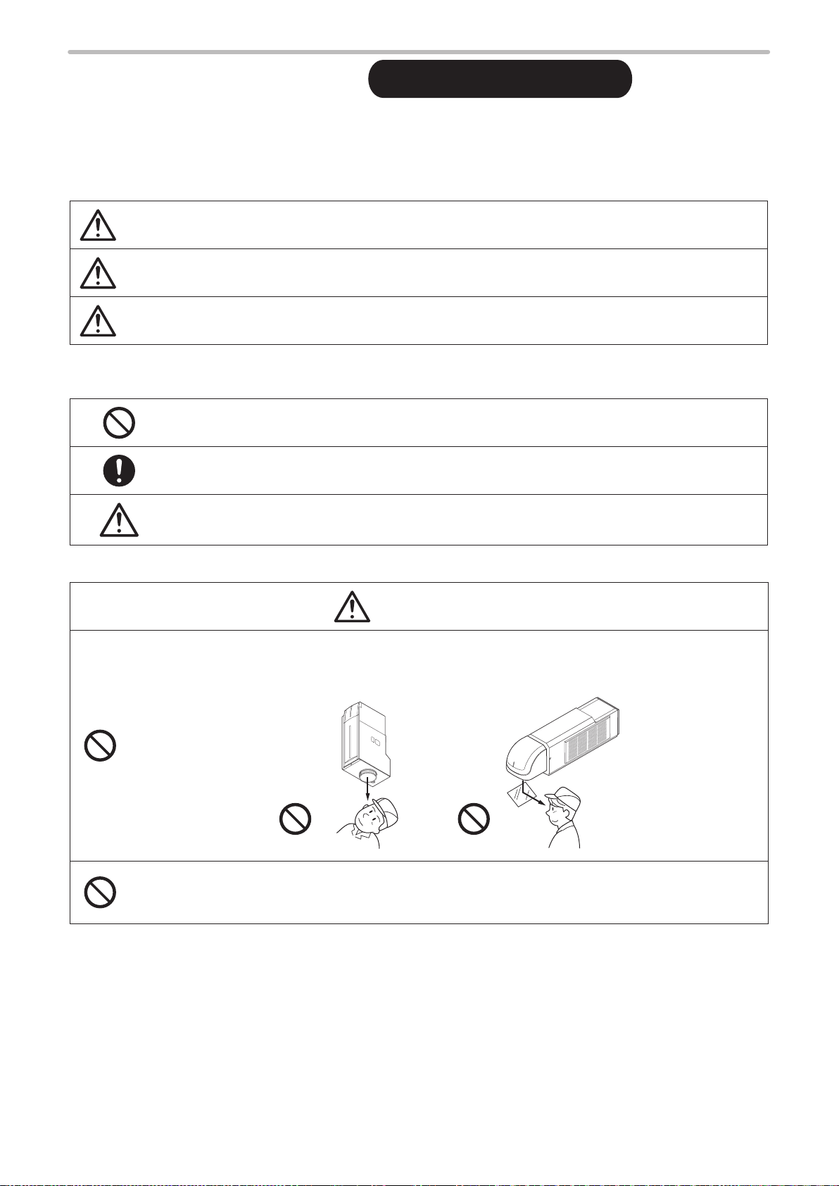
DANGER
• Never look at laser beam directly, through lens or through any other optical components. Laser beam
radiation into the eye causes blindness or serious damage to the eye.
Not only the direct beam of laser, but also diffused reected beam is harmful.
• Never touch laser beam and avoid human skin, clothing and any other ammable object from laser beam
exposure directly.
Burning into deep skin might result and there is a risk of re.
3
WARNING
• Do not use this product anywhere where re is strictly prohibited, near inammable gas, objects or organic
ME-LP400V-OP-6
solvents such as thinner or gasoline, or in dusty place. There is a risk of re.
• Do not use this product in wet place. In addition, never conduct wiring or maintenance work with wet hands
or when the product surface is wet. Otherwise, electric shock and/or malfunction may result.
• Never disassemble the product.
Doing so may cause exposure to the laser beam or electric shock.
• Do not insert hands or objects between the gaps of the exhaust port or inspiratory port.
There is a risk of electrical shock or injury.
• For LP-V / LP-W series, be careful neither to give strong power to the ber cable nor to nip it for installation.
Do not install the product to the systems that give excessive load acts on the ber cable, such as head
movement unit.
If the ber cable is damaged, laser beam comes out from the cable and it may cause laser exposures.
• Take laser protection measures required to use Class 4 laser products subject to the local laws and
regulations of the country or region in which this laser product is used.
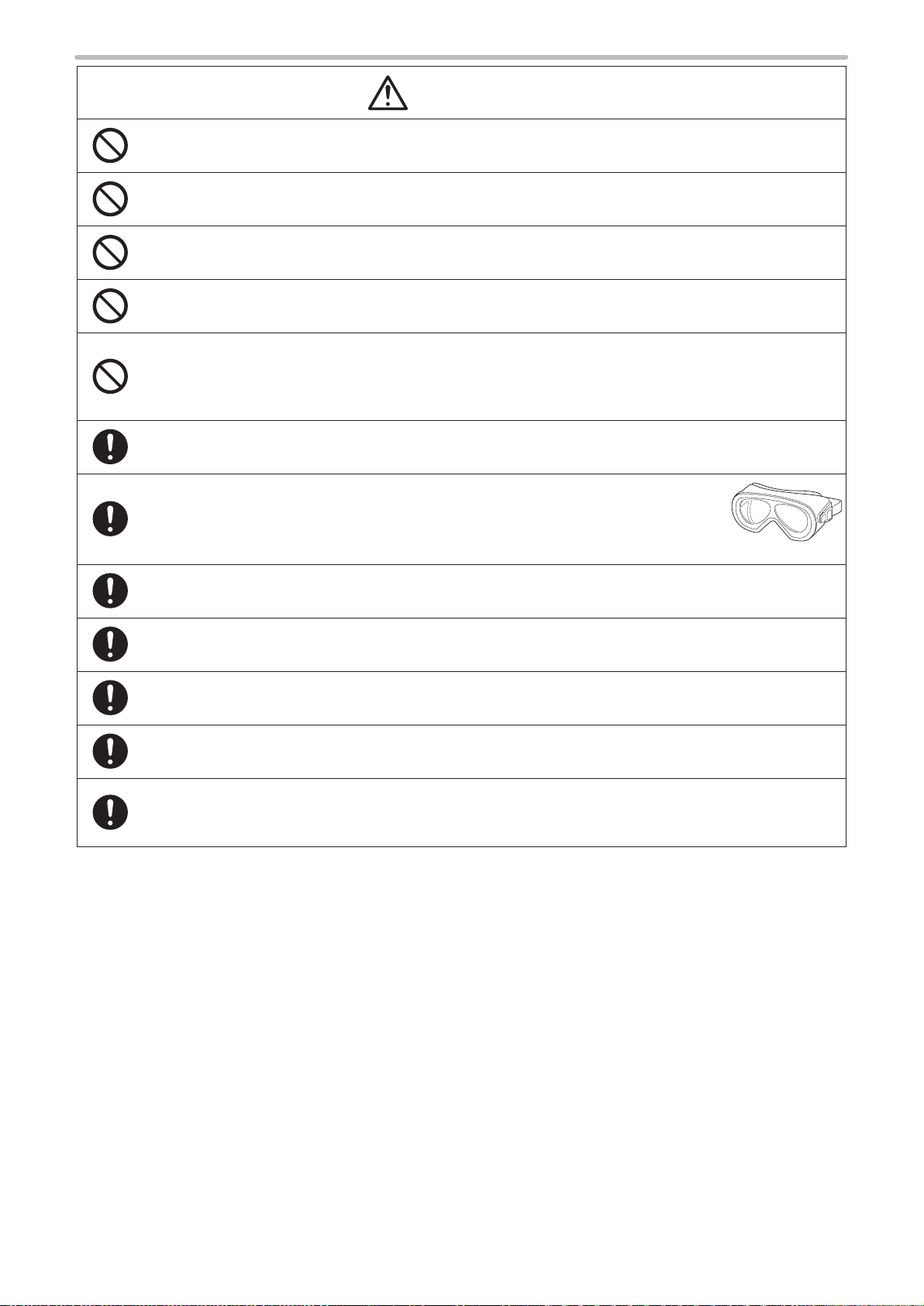
• To protect the operators’ eyes, make it mandatory to wear goggles against laser beam
within the laser controlled area. The protective goggles can momentarily protect the
eyes against the scattered beam. Never look at the direct beam or reected beam
even when you are wearing the protective goggles.
• Construct an interlock systems such as a function to stop laser radiation for the maintenance door of the
protective enclosure.
• Set protective enclosure with proper reectance, durability and thermal resistance to enclose the laser
radiation area without leakage.
• After power supply of laser marker is turned off, laser safety manager must remove the key and keep it.
• Be sure to connect the head to the exclusive controller. It will cause exposure of laser beam and a failure if it
connects with any equipment other than the exclusive controller.
• Read all packaged guides and manuals thoroughly, and do not operate, install and connect the laser marker
with any other methods except the instructions provided in the manuals. Inappropriate use might cause
injury, electrical shock or exposure of laser beam.
4

WARNING
• Remove the dust and/or gas which may be generated during the laser radiation with dust collector or
ME-LP400V-OP-6
exhauster. Use an appropriate dust collector or exhauster for dust or gas generated.
Depending on the material of the objects, harmful dust and/or gas to the human body and the laser marker
may be generated.
Dust collector
Protective enclosure
• When using the assist gas for laser processing, take safety precautions to protect operators from exposure,
ignition, toxic effect, excess or lack of oxygen.
• Prior to wiring, cable connecting, and/or maintenance work, ensure that all the power switches are turned
off. Otherwise, electrical shock may result.
• The wiring and maintenance must be conducted by the electrical engineers or under their supervision.
Incorrect work may cause electrical shock.
• Connect ground wire before using. A failure or electrical leakage that occurs when the unit is not properly
grounded may result in electric shock.
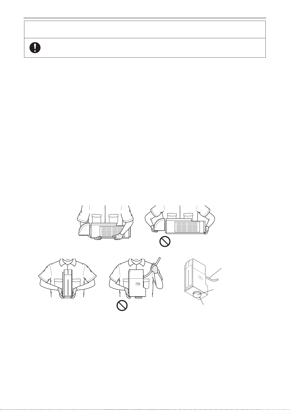
• To carry this product, wear the non-slip gloves and safety shoes, hold the bottom of the unit as shown below
gure. Carry the controller unit with two persons.
• Install this product in the stable place without vibration and shock.
• In case it falls down, it may cause injury.
Controller
5
For the Proper Use of Product
ME-LP400V-OP-6
• Be sure to observe the following matters to prevent a failure or a malfunction of this product and to maintain
the product performance properly.
Usage environment
• Do not use the product in a place with frequent vibrations or shocks. Moreover, please do not drop this product. It
may affect the precision component and optical component inside, which could impair the performance or result in a
failure.
• Do not use the system outdoors.
• The product is air-cooled. Please install not to bar the ow of air cooling. Avoid placing heat sources near the product.
• Be sure to use the product within the ambient temperature and humidity dened in the specications.
• Be careful not to have water, oil, ngerprints, dust, or dirt attached to the laser emission port of the head. This could
degrade the lasing performance and may result in a failure. If the laser emission port becomes dirty, use a dry soft
cloth to clean the port.
• If the air lter becomes dirt, clean the lter. Failure to do so may hinder the air ow, resulting in failure of this product.
Replace air lter periodically.
• Ensure that the dust or gas are removed by placing the intake duct of the dust collector or exhauster near the source
of dust or gas. Any dust or gas contamination on the laser emission port may cause failure or decrease the laser
marking or processing quality. In addition, when the laser beam is blocked by dust or gas, it may cause decrease in
laser marking or processing quality.
Installation and mounting
• Do not hold the cables and connectors at carrying this product.
• Do not touch the laser emission port on the bottom of the head. They may affect the laser marking quality badly.
• For LP-V / LP-W series, do not grasp the ber unit when carrying the head part.
• Carry the head as shown in the gure below.
LP-400 series
OK
LP-V/LP-W series
OK
• Do not install the product to the systems that give excessive load acts on the head and cables, such as head
movement unit. Failure to do so may damage the head precision parts or disconnect the cables, resulting in a failure.
• Be careful neither to give strong power to the cables nor to nip it for installation.
• Verify the minimum bend radius of each cable and install them without excess forces being applied.
• Do not hit the device with a tool such as a hammer at the installation. Do not use excessive force while tightening the
screws (nuts). It may cause a failure.
• Do not insert any objects between the gaps of the exhaust port or inspiratory port.
• Use anti-reection material (ex. black paint for metal) for an external shutter or a protective enclosure in a path of
laser beam. It may cause a failure of the components inside the laser marker head.
• If any other devices such as a sensor or a camera are installed near the laser marker, make sure that these devices
are installed in the place where laser beam and its reected beam do not damage to them.
NG
NG
Fiber cable
Laser emission port
Laser pointer emission port
6

For the Proper Use of Product
ME-LP400V-OP-6
• Be sure to observe the following matters to prevent a failure or a malfunction of this product and to maintain
the product performance properly.
Wiring
• Verify that the cables are wired correctly before powering on.
• For the connection of this product, use the dedicated cables attached to the product or the specied optional cables.
• Check the voltage uctuations of the power supply. Do not input the power supply exceeding the rating.
• If a surge occurs in the power supplied, connect a surge absorber to a source of the surge to absorb it.
• Be sure to take measures against surge before connecting any induction load such as DC relay to the load.
• The output has no protection function for short-circuit, therefore, do not connect the power supply or capacitive load
directly.
• Make sure to ground the frame ground terminal of this product.
• Install such that the controller housing and the head housing are at the same electric potential.
• Each connecting cable should not be used in the same raceway or connected in parallel to any device that generates
high-tension wires, power lines, large switching surge or the like. There is a risk of malfunction caused by induction.
• USB cable should not be connected in parallel with the controller power cable or the motor power cable.
• Make the wiring as short as possible to prevent a malfunction by the noise.
Operation
• Do not turn off the power supply until completing the system start.
• In case of turning ON the power supply after turning OFF, leave the interval at least 5 seconds between ON and OFF.
• The following items, Date, Lot, and Expiry Date are marked based on the internal clock of the laser marker. The
internal clock might be deviated due to error of the internal parts or degree of the battery drain, ambient temperature
and humidity. Therefore, be sure to check the time of the internal clock before the operation.
• Do not remove the USB media nor turn off the power during the data writing and reading operation.
Others
• Be sure to delete all registered data when transferring or discarding this product. Retained data might result in illegal
read out and leaking of information by a third-party with malicious intent.
7

General Terms and Conditions
ME-LP400V-OP-6
Although we are striving to improve quality and reliability of our products, failure in electric components and devices may happen with
a certain probability. It is highly recommended to employ fail-safe designs, including redundant design, ame propagation prevention
design, and malfunction prevention design, as well as periodical maintenance to avoid any risk of bodily injury, re accident, or social
damage due to any failure of our products.
Please read carefully and accept the following “Cautions for Safe Use” and “Warranty Policy” before using our products.
1. PRODUCT MODIFICATIONS & DISCONTINUANCE:
Panasonic Industrial Devices SUNX expressly reserves the right to modify, including the right to discontinue, any of the Products,
prior to their order, from time to time without notice.
2. WARRANTIES:
(1) Subject to the exclusions stated in 3 (EXCLUSIONS) herein below, Panasonic Industrial Devices SUNX warrants the Products
to be free of defects in material and workmanship for a period of one (1) year from the date of shipment under normal usage in
environments commonly found in manufacturing industry.
(2) Any Products found to be defective must be shipped to Panasonic Industrial Devices SUNX with all shipping costs paid by
Purchaser for inspection and examination. Upon examination by Panasonic Industrial Devices SUNX, Panasonic Industrial
Devices SUNX will, at its sole discretion, repair or replace at no charge, or refund the purchaser price of, any Products found to be
defective.
3. EXCLUSIONS:
(1) This warranty does not apply to defects resulting from any cause:
(i) which was due to abuse, misuse, mishandling, improper installation, improper interfacing, or improper repair by Purchaser;
(ii) which was due to unauthorized modication by Purchaser, in part or in whole, whether in structure, performance or
specication;
(iii) which was not discoverable by a person with the state-of-the-art scientic and technical knowledge at the time of manufacture;
(iv) which was due to an operation or use by Purchaser outside of the limits of operation or environment specied by Panasonic
Industrial Devices SUNX;
(v) which was due to Force Majeure; and
(vi) which was due to any use or application expressly discouraged by Panasonic Industrial Devices SUNX in 5 (CAUTIONS FOR
SAFE USE) hereunder.
(2) This warranty extends only to the rst purchaser for application, and is not transferable to any person or entity which purchased
from such purchaser for application.
4. DISCLAIMERS:
(1) Panasonic Industrial Devices SUNX’s sole obligation and liability under this warranty is limited to the repair or replacement, or
refund of the purchase price, of a defective Product, at Panasonic Industrial Devices SUNX’s option.
(2) THE REPAIR, REPLACEMENT, OR REFUND IS THE EXCLUSIVE REMEDY OF THE PURCHASER, AND ALL OTHER
WARRANTIES, EXPRESS OR IMPLIED, INCLUDING, WITHOUT LIMITATION, THE WARR ANTIES OF MERCHANTABILITY,
FITNESS FOR A PARTICULAR PURPOSE, AND NON-INFRINGEMENT OF PROPRIETARY RIGHTS, ARE HEREBY
EXPRESSLY DISCLAIMED. IN NO EVENT SHALL PANASONIC INDUSTRIAL DEVICES SUNX AND ITS AFFILIATED ENTITIES
BE LIABLE FOR DAMAGES IN EXCESS OF THE PURCHASE PRICE OF THE PRODUCTS, OR FOR ANY INDIRECT,
INCIDENTAL, SPECIAL OR CONSEQUENTIAL DAMAGES OF ANY KIND, OR ANY DAMAGES RESULTING FROM LOSS OF
USE, BUSINESS INTERRUPTION, LOSS OF INFORMATION, LOSS OR INACCURACY OF DATA, LOSS OF PROFITS, LOSS
OF SAVINGS, THE COST OF PROCUREMENT OF SUBSTITUTED GOODS, SERVICES OR TECHNOLOGIES, OR FOR ANY
MATTER ARISING OUT OF OR IN CONNECTION WITH THE USE OR INABILITY TO USE THE PRODUCTS.
5. CAUTIONS FOR SAFE USE:
(1) It is Purchaser’s sole responsibility to ascertain the tness and suitability of the Products for any particular application, as well as
to abide by Purchaser’s applicable local laws and regulations, if any.
(2) In incorporating the Products to any equipment, facilities or systems, it is highly recommended to employ fail-safe designs,
including but not limited to a redundant design, ame propagation prevention design, and malfunction prevention design so as not
to cause any risk of bodily injury, re accident, or social damage due to any failure of such equipment, facilities or systems,
(3) The Products are each intended for use only in environments commonly found in manufacturing industr y, and, unless expressly
allowed in the manual, specication or otherwise, shall not be used in, or incorporated into, any equipment, facilities or systems,
such as those:
(i) which are used for the protection of human life or body parts;
(ii) which are used outdoors or in environments subject to any likelihood of chemical contamination or electromagnetic inuence;
(iii) which are likely to be used beyond the limits of operations or environments specied by Panasonic Industrial Devices SUNX in
this document or otherwise;
(iv) which may cause risk to life or property, such as nuclear energy control equipment, transportation equipment whether on rail or
land, or in air or at sea, and medical equipment;
(v) which other wise require a high level of safety performance similar to that required in those equipment, facilities or systems as
listed in (i) through (iv) above.
6. EXPORT CONTROL LAWS:
In some jurisdictions, the Products may be subject to local expor t laws and regulations. If any diversion or re-export is to be made,
Purchaser is advised to abide by such local export laws and regulations, if any, at its own responsibility.
7. PURCHASER’S TRANSFER OBLIGATIONS:
If Purchaser resell or deliver the Products to a third party, Purchaser must provide such third party with a copy of this document, all
specications, manuals, catalogs, leaets and written information of any kind provided to Purchaser by Panasonic Industrial Devices
SUNX or its authorized local representative from time to time regarding the Products.
8
Applicable Standards and Related Regulations
ME-LP400V-OP-6
Applicable standards
This product is designed to meet the following standards according to the model.
Note that our products do not conform to the safety standards of the countries and regions not listed in the applicable
standards section. When exporting the product by itself or integrated into machine or device, conrm the regulations and
standards of the exporting country or region.
Model Applicable standards and regulations
LP-430(T)U / LP-431(T)U / LP-435(T)U /
LP-420S9(T)U / LP-421S9(T)U
LP-425S9(T)U / LP-410(T)U / LP- 411(T)U
LP-V10U / LP-V15U / LP-W052U
LP-430(T)U-A / LP-431(T)U-A
LP-435(T)U-A / LP-420S9(T)U-A
LP-421S9(T)U-A / LP-425S9(T)U-A
LP-410(T)U-A / LP-411(T)U-A
LP-V10U-A / LP-V15U-A / LP-W052U-A
LP-430(T)U-C / LP-431(T)U-C
LP-435(T)U-C / LP-420S9(T)U-C
LP-421S9(T)U-C / LP-425S9(T)U-C
LP-410(T)U-C / LP-411(T)U-C
LP-V10U-C / LP-V15U-C
JIS (Japanese Industrial Standards)
• JIS C 6802: 2014 “Safety of laser products”
FDA (Food and Drug Administration) Regulations
• 21 CFR1040.10 and 1040.11 except for deviations pursuant to Laser
Notice No. 50 “PART 1040 PERFORMANCE STANDARDS FOR
LIGHT-EMITTING PRODUCTS”
EN Standard (CE Marking) *1
• 2014/30/EU “EMC Directive”
• EN55011: 2009+A1: 2010 “Industrial, scientic and medical
equipment. Radio-frequency disturbance characteristics. Limits and
methods of measurement”
• EN61000-6-2: 2005 “Electromagnetic compatibility (EMC). Generic
standards. Immunity for industrial environments”
• 2014/35/EU “Low Voltage Directive”
• EN60204-1: 2006+A1: 2009 “Safety of machinery. Electrical
equipment of machines. General requirements”
• (partially applied *2) EN61010-1: 2010 “Safety requirements for
electrical equipment for measurement, control, and laboratory use.
General requirements”
• EN60825-1: 2014 “Safety of laser products. Equipment classication
and requirements”
• 2011/65/EU “RoHS Directive”
• EN 50581:2012 “Technical documentation for the assessment of
electrical and electronic products with respect to the restriction of
hazardous substances”
LP-430(T)U-CHN / LP-431(T)U-CHN
LP-435(T)U-CHN / LP-420S9(T)U-CHN
LP-421S9(T)U-CHN / LP-425S9(T)U-CHN
LP-410(T)U-CHN / LP-411(T)U-CHN
LP-V10U-CHN / LP-V15U-CHN
*1 : Contact for CE:
Panasonic Marketing Europe GmbH, Panasonic Testing Center
Winsbergring 15, 22525 Hamburg, Germany
*2 : Although EN 60204-1 is applied as a harmonized standard of LVD, EN 61010-1 is partially applied to enhance the
conformity with electrical safety and requirement of LVD.
• Construct a safety system before using this product as it is a class 4 laser product.
GB (Chinese National Standard)
• GB 7247.1-2012 (idt IEC60825-1: 2007)
备分类、要求”
“激光产品的安全 第 1 部分 : 设
9

Implementing safety measures for the laser products
ME-LP400V-OP-6
This product uses the Class 4 laser classied by the safety of laser products in JIS C6802, IEC60825-1, FDA standards 21
CFR 1040.10 and 1040.11.
Class 4 laser refers to “Laser products for which intrabeam viewing and skin exposure is hazardous and for which the
viewing of diffuse reections may be hazardous. These lasers also often represent a re hazard.”
To avoid injuries of the workers who handle the laser equipment or who may be exposed to the laser beam, use the
product safely and properly by observing the matters listed in the “For the Safety Use of Laser Product” (P.20) as well as the
standards and regulations of the region where this product will be used.
Removing and eliminating dust or gas
Depending on the laser radiation objects, noxious dust or gas may generate by the laser radiation, which could harm
human body or the environment.
Eliminate dust or gas generated using a dust collector or an exhauster according to the constituent of such dust or gas.
Dispose of the exhaust gas safely and appropriately according to the laws and regulations of the country, region, or area
applicable.
Attention for the laser marker disposal
For disposal of this product, segregate and dispose of it appropriately according to the laws and regulations of the country,
region, or area applicable.
Batteries, when disposed in the European Union, must be separately collected in accordance with the EU Battery Directive
(2006/66/EC). EU Battery Directive (2006/66/EC) obliges separate collection and recycling of batteries that were used in
the European Union.
Refer to “Disposal of Laser Marker” (P.289).
Conformity registration of KC mark (Korea Certication)
The following laser marker models get the KC mark registration.
Model
LP-430U-C, LP-430TU-C
LP-431U-C, LP-431TU-C
LP-435U-C, LP-435TU-C
LP-420S9U-C, LP-420S9TU-C
LP-421S9U-C, LP-421S9TU-C
LP-425S9U-C, LP-425S9TU-C
LP-410U-C, LP-410TU-C
LP-411U-C, LP- 411TU-C
LP-V10U-C
LP-V15U-C
KC mark (Korea Certication):
Class A Equipment (Industrial Broadcasting & Communication Equipment)
This equipment is Industrial (Class A) electromagnetic wave suitability equipment and seller or user should take notice of it,
and this equipment is to be used in the places except for home.
A 급 기기 ( 업무용 방송통신기자재 )
이 기기는 업무용 (A 급 ) 전자파적합기기로서 판매자 또는 사용자는 이 점을 주의하시기 바라며 , 가정외의 지역에서 사용하는
것을 목적으로 합니다 .
10

MEMO
ME-LP400V-OP-6
11
How to Read this Document
ME-LP400V-OP-6
Target laser marker
⿎
This document is subject to the following Laser Marker models.
In this document, “laser marker” means this product.
If the setting contents or specications vary by models, the target models are specied in the text. (The target models are
not specied for items which are common to all models.) In the text, multiple models may be described collectively, as
shown in the table below.
Note that the illustration and the screen images may vary with model.
Target model Description in the text
LP-430U, LP-430TU LP-4xx(T)U LP-430 LP-4x0 LP-400 Series
LP-430U-A, LP- 430TU-A LP-4xx(T)U-A
LP-430U-C, LP-430TU-C LP-4xx(T)U-C
LP-430U-CHN, LP-430TU-CHN LP-4xx(T)U-CHN
LP-420S9U, LP-420S9TU LP-4xxS9(T)U LP-420
LP-420S9U-A, LP-420S9TU-A LP-4xxS9(T)U-A
LP-420S9U-C, LP-420S9TU-C LP-4xxS9(T)U-C
LP-420S9U-CHN, LP- 420S9TU-CHN LP-4xxS9(T)U-CHN
LP-410U, LP-410TU LP-4xx(T)U LP-410
LP-410U-A, LP-410TU-A LP-4xx(T)U-A
LP-410U-C, LP-410TU-C LP-4xx(T)U-C
LP-410U-CHN, LP-410TU-CHN LP-4xx(T)U-CHN
LP-435U, LP-435TU LP-4xx(T)U LP-435 LP-4x5
LP-435U-A, LP-435TU-A LP-4xx(T)U-A
LP-435U-C, LP-435TU-C LP-4xx(T)U-C
LP-435U-CHN, LP- 435TU-CHN LP-4xx(T)U-CHN
LP-425S9U, LP-425S9TU LP-4xxS9(T)U LP-425
LP-425S9U-A, LP-425S9TU-A LP-4xxS9(T)U-A
LP-425S9U-C, LP-425S9TU-C LP-4xxS9(T)U-C
LP-425S9U-CHN, LP- 425S9TU-CHN LP-4xxS9(T)U-CHN
LP-431U, LP-431TU LP-4xx(T)U LP-431 LP-4x1
LP-431U-A, LP-431TU-A LP-4xx(T)U-A
LP-431U-C, LP-431TU-C LP-4xx(T)U-C
LP-431U-CHN, LP-431TU-CHN LP-4xx(T)U-CHN
LP-421S9U, LP-421S9TU LP-4xxS9(T)U LP-421
LP-421S9U-A, LP-421S9TU-A LP-4xxS9(T)U-A
LP-421S9U-C, LP-421S9TU-C LP-4xxS9(T)U-C
LP-421S9U-CHN, LP- 421S9TU-CHN LP-4xxS9(T)U-CHN
LP-411U, LP-411TU LP-4xx(T)U LP-411
LP-411U-A, LP-411TU-A LP-4xx(T)U-A
LP-411U-C, LP- 411TU-C LP-4xx(T)U-C
LP-411U-CHN, LP-411TU-CHN LP-4xx(T)U-CHN
LP-V10U LP-VxxU LP-V10 LP-V Series
LP-V10U-A LP-VxxU-A
LP-V10U-C LP-VxxU-C
LP-V10U-CHN LP-VxxU-CHN
LP-V15U LP-VxxU LP-V15
LP-V15U-A LP-VxxU-A
LP-V15U-C LP-VxxU-C
LP-V15U-CHN LP-VxxU-CHN
LP-W052U LP-W052U LP-W052 LP-W Series
LP-W052U-A LP-W052U-A
12
Symbol indications
ME-LP400V-OP-6
⿎
Notice
Reference
Type of manuals
⿎
For this product the following manuals are prepared. Read each manuals and operate this product correctly and safely.
Save the manuals for future use.
• “Notice” denotes any instructions or precautions for using this product. To prevent the
damage or malfunction of the product, observe these precautions fully.
• “Reference” denotes any hints for operation, detail explanations, or references.
Operation/Maintenance Manual
This manual describes the safety precautions and the items required for the installation, operation and maintenance of
the laser marker.
• Precautions and safety measures: All users shall be required for reading this part.
• Specications and outer dimensions
• Setup and connecting method
• How to operate the laser marker and set the marking data using touch panel console or monitor and mouse.
• Maintenance
• Troubleshooting
External Control Manual
This manual describes how to control this product externally using I/O signals and serial communication (RS-232C/
Ethernet) commands.
Mainly the machine builder and system integrator shall be required for reading this manual.
• I/O control method (interfaces, signal layout, I/O rating, timing chart etc.)
• Command control method (serial communication interfaces, communication settings, command data formats etc.)
Laser Maker NAVI Operation Manual
This manual describes how to operate the laser marker and set the marking data using PC setting software “Laser
Marker NAVI”.
Reference
• The PDF data of each manual are included on an attached CD-ROM “Laser Marker Driver & Utility”.
• To read the PDF manual, Adobe Reader (Version 7 or later) of Adobe Systems Incorporated is required.
13
Expiry DateExpiry Date
…
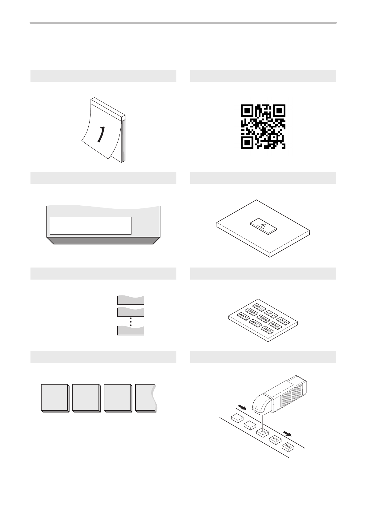
“Let’s Try” Contents
ME-LP400V-OP-6
The user can refer to the corresponding pages in which the contents of what user “tries to do” are described using this “Let's
Try” Contents.
Mark Current Date/Time Mark Code Symbol
P.91
January
P.105
Mark Expiry Date/Time Mark Logo
P.94
2020.04.01
.
P.110
Mark Lot Mark Step & Repeat
P.98
January
February
December
Ѝ
Ѝ
Ѝ
JAN
FEB
DEC
P.113
Mark Counter Mark to Flying Object
P.101
0001 0002 0003 0004
P.117
14
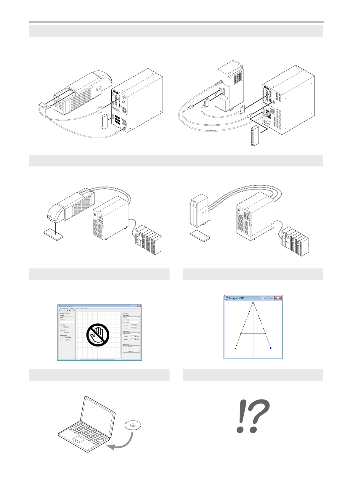
Install and Connect Laser Marker
ME-LP400V-OP-6
“2-1 Installation” (P.59)
“2-2 Connecting Laser Marker” (P.72)
Control by I/O or RS-232C / Ethernet
External Control Manual
ABC
ABC
Convert or Edit Graphic Data Create or Edit Making Font
• Logo Data Conversion Software Operation Manual
• Logo Data Editing Software Operation Manual
Font Maker Operation Manual
Install Laser Marker NAVI When in Trouble...
Laser Marker NAVI Operation Manual “Troubleshooting” (P.291)
15

Contents
ME-LP400V-OP-6
Preface ……………………………………………………………………………… 2
Cautions in Handling
Applicable Standards and Related Regulations
How to Read this Document
“Let’s Try” Contents
For the Safety Use of Laser Product
Radiation Information [LP-400 Series]
Radiation Information [LP-V/LP-W Series]
Safety Protection Measures for Users
Safety Functions on Laser Marker
………………………………………………………………… 3
………………………………… 9
……………………………………………………… 12
…………………………………………………………………14
………………………………………………20
………………………………………20
…………………………………23
………………………………………25
……………………………………………27
1 Product Overview ……………………………………………………32
1-1 Product Model ……………………………………………………………………33
1-2 Product Conguration …………………………………………………………35
1-3 Specication ……………………………………………………………………36
1-4 Outer Dimensional Drawing ……………………………………………………40
1-4-1 LP-400 Series …………………………………………………………40
1-4-2 LP-V/LP-W Series ………………………………………………………43
1-4-3 Cable ……………………………………………………………………45
1-4-4 Console (Option) ………………………………………………………46
1-5 Package …………………………………………………………………………47
1-6 Name of Each Part ……………………………………………………………49
1-6-1 Head ……………………………………………………………………49
1-6-2 Controller ………………………………………………………………53
1-6-3 DIP Switch ………………………………………………………………57
2 Installation and Connection …………………………………………58
2-1 Installation ………………………………………………………………………59
2-1-1 Installation Environment ………………………………………………59
2-1-2 Installation of LP-400 Series Head ……………………………………61
2-1-3 Rotation of LP-400 Standard Head Scanner ………………………64
2-1-4 Installation of LP-V / LP-W Head ……………………………………65
2-1-5 Installation of the Controller ……………………………………………67
2-1-6 Marking Field and Marking Center Position …………………………68
2-1-7 Lasing position check …………………………………………………69
2-1-8 Focus adjustment function ……………………………………………70
2-2 Connecting Laser Marker ………………………………………………………72
2-2-1 Connecting Head, Controller, Terminal Block ………………………72
2-2-2 Connecting Ground and Power Supply ……………………………… 74
2-2-3 When Using PC …………………………………………………………75
16

2-2-4 When Using Console (Option) ………………………………………76
ME-LP400V-OP-6
2-2-5 When Using Monitor and Mouse ……………………………………76
3 Basic Operation Procedure …………………………………………77
3-1 Display Operation ………………………………………………………………78
3-2 Operation Overview ……………………………………………………………80
3-2-1 Setup and connect the laser marker …………………………………81
3-2-2 Startup of Laser Marker ………………………………………………82
3-2-3 Set the marking data …………………………………………………83
3-2-4 Radiate the laser ………………………………………………………87
3-2-5 Save the marking data …………………………………………………89
3-2-6 Turn OFF Power of Laser Marker ……………………………………90
3-3 Setting Procedure for Basic Function …………………………………………91
3-3-1 Mark Current Date/Time ………………………………………………91
3-3-2 Mark Expiry Date/Time ………………………………………………94
3-3-3 Mark Lot No. ……………………………………………………………98
3-3-4 Mark Counter ……………………………………………………… 101
3-3-5 Mark Code Symbol ………………………………………………… 105
3-3-6 Mark Logo …………………………………………………………… 110
3-3-7 Mark Step & Repeat ………………………………………………… 113
3-3-8 Mark to Flying Object ……………………………………………… 117
4 Description of Operation Screen ……………………………… 121
4-1 Screen Composition ………………………………………………………… 122
4-2 Functional Description ……………………………………………………… 124
4-3 Operation Screen …………………………………………………………… 126
4-3-1 Character Display …………………………………………………… 126
4-3-2 Image Display ……………………………………………………… 127
4-3-3 Password to Open the Setting Screen …………………………… 128
4-4 Operator Adjustment Screen ……………………………………………… 129
4-4-1 Operator Adjusting Screen ………………………………………… 129
4-4-2 Operator Adjustable Items ………………………………………… 130
4-5 Maintenance ………………………………………………………………… 133
4-5-1 I/O Check Monitor …………………………………………………… 133
4-5-2 Error Log …………………………………………………………… 134
4-6 Selecting Marking Mode …………………………………………………… 135
4-6-1 Dual pointer ………………………………………………………… 136
4-6-2 Guide laser ………………………………………………………… 137
4-6-3 Test Marking ………………………………………………………… 138
4-6-4 RUN Mode…………………………………………………………… 139
4-7 FILE …………………………………………………………………………… 140
4-7-1 Comment …………………………………………………………… 140
4-7-2 Change File No. ……………………………………………………… 141
17

4-7-3 Save ………………………………………………………………… 142
ME-LP400V-OP-6
4-7-4 Save to Different No. ……………………………………………… 143
4-7-5 New Creation ………………………………………………………… 144
4-8 Character Setting …………………………………………………………… 145
4-8-1 Character Type ……………………………………………………… 145
4-8-2 Character Input ……………………………………………………… 148
4-8-3 Editing Character …………………………………………………… 151
4-8-4 Function Character ………………………………………………… 153
4-9 Function Setting ……………………………………………………………… 162
4-9-1 Expiry Date ………………………………………………………… 162
4-9-2 Counter ……………………………………………………………… 164
4-9-3 Lot …………………………………………………………………… 166
4-9-4 Rank ………………………………………………………………… 168
4-9-5 External Offset ……………………………………………………… 170
4-10 Marking Condition ………………………………………………………… 173
4-10-1 General Condition ………………………………………………… 173
4-10-2 Character Conditions ……………………………………………… 180
4-10-3 Logo Condition …………………………………………………… 186
4-10-4 Bar Code Condition ……………………………………………… 188
4-10-5 Processing Condition ……………………………………………… 207
4-10-6 Point Radiation Condition ………………………………………… 212
4-11 Laser Setting ………………………………………………………………… 214
4-11-1 Setting Parameters ………………………………………………… 214
4-11-2 Detail Adjustment (Laser Setting) ………………………………… 217
4-12 Trigger Setting ……………………………………………………………… 219
4-12-1 Marking to Static Work …………………………………………… 219
4-12-2 Marking to Flying Object ………………………………………… 220
4-13 Common Setting …………………………………………………………… 232
4-13-1 Common Character Setting ……………………………………… 233
4-13-2 Common Expiry Date ……………………………………………… 234
4-13-3 Common Counter ………………………………………………… 235
4-13-4 Common Lot ……………………………………………………… 237
4-14 Image Display Screen ……………………………………………………… 239
4-14-1 Image Display ……………………………………………………… 239
4-14-2 Work Image Display ……………………………………………… 240
4-15 USB Media ………………………………………………………………… 241
4-15-1 Registration File …………………………………………………… 241
4-15-2 Common File ……………………………………………………… 242
4-15-3 Logo File …………………………………………………………… 243
4-15-4 Font File …………………………………………………………… 244
4-15-5 File Management ………………………………………………… 246
4-15-6 Backup ……………………………………………………………… 249
4-16 Environment Setting ……………………………………………………… 253
18

4-16-1 Display Setting (Environment 1) ………………………………… 253
ME-LP400V-OP-6
4-16-2 System Setting (Environment 2) ………………………………… 258
4-16-3 Communication, I/O Setting (Environment 3) …………………… 261
4-16-4 Power check ……………………………………………………… 265
4-16-5 Output Simulation ………………………………………………… 267
4-16-6 Adjustment of Touch Panel ……………………………………… 268
4-16-7 Language Selection ……………………………………………… 269
4-16-8 System Information………………………………………………… 270
Maintenance ………………………………………………………… 272
Maintenance Items ……………………………………………………………… 273
Maintenance Details of Parts
Laser emission port (fθ lens)
Cleaning / Replacement of Laser Emission Port
Intake/exhaust vent
Air lter
Air-cooling fan
Laser oscillator
Galvano scanner
Internal shutter
Battery inside the controller
Replacement of fuse
Replacement of cable
Obtaining Backup Data
Serial No. Checking Method
Disposal of Laser Marker
Cautions for separate disposal of head of LP-400 series
Disposal of old equipment and batteries
……………………………………………………………………… 279
……………………………………………………………… 280
……………………………………………………………… 281
…………………………………………………………… 284
……………………………………………………………… 285
…………………………………………………… 274
……………………………………………… 274
………………………………………………………… 278
……………………………………………… 285
……………………………………………………… 286
……………………………………………………… 286
…………………………………………………………… 287
…………………………………………………… 288
………………………………………………………… 289
………………………………… 289
………………………… 276
……………… 289
Troubleshooting ……………………………………………………… 291
Troubleshooting …………………………………………………………………… 292
Error Indication
Alarm
Warning
…………………………………………………………………… 301
………………………………………………………………………… 301
……………………………………………………………………… 304
Appendix …………………………………………………………… 308
Description of Code Symbols …………………………………………………… 309
Readable DXF File
……………………………………………………………… 326
Index ………………………………………………………………… 328
Index ……………………………………………………………………………… 329
19
For the Safety Use of Laser Product
ME-LP400V-OP-6
This product falls into Class 4 laser (marking laser) and Class 2 laser (guide laser) based on the classications of “Safety
of laser products” IEC60825-1 and FDA standards 21 CFR 1040.10 and 1040.11. Perform the safety protection measure
before using the system. Refer to “Safety Protection Measures for Users” (P.25) for details.
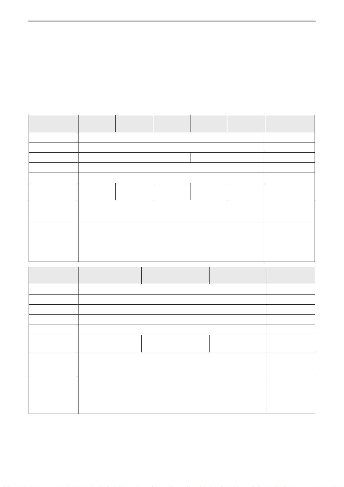
Radiation Information [LP-400 Series]
Marking Laser (Class 4)
⿎
Class 4 laser refers to “Laser products for which intrabeam viewing and skin exposure is hazardous and for which the
viewing of diffuse reections may be hazardous. These lasers also often represent a re hazard.”
Model Name
Wavelength 10.6 μm Invisible beam
Laser Medium CO
Max. Output *1 75 W 30 W ―
Mode of Operation CW (continuous wave) ―
Class 4 ―
NOHD *2 4.9 m 3 m 6.9 m 2.5 m 1.5 m
MPE *3 1000 W/m
NHZ
Model Name
LP-430U
LP-430TU
NHZ represents the area where the amount of beam irradiance or radiant
exposure exceeds the maximum permissible exposure to eyes. It is equal of
NOHD at a maximum.
NHZ varies depending on the reectance or surface condition of works.
Please calculate it based on the actual working environment.
LP-420S9U
LP-420S9TU
LP-431U
LP-431TU
LP-435U
LP-435TU
Laser ―
2
LP-421S9U
LP-421S9TU
2
LP-410U
LP-410TU
LP-411U
LP-411TU
LP-425S9U
LP-425S9TU
Remarks
Nominal ocular
hazard distance
Maximum
Permissible
Exposure
Nominal hazard
zone
Remarks
Wavelength 9.3 μm Invisible beam
Laser Medium CO
Max. Output *1 75 W ―
Mode of Operation CW (continuous wave) ―
Class 4 ―
NOHD *2 4.9 m 3 m 6.9 m
MPE *3 1000 W/m
NHZ represents the area where the amount of beam irradiance or radiant
exposure exceeds the maximum permissible exposure to eyes. It is equal of
NHZ
*1 : The maximum output power means the maximum value of output that can be output from a laser oscillator itself.
Refer to “1-3 Specication” (P.36) for details of average output.
*2 : “NOHD” means the distance that the area where the amount of beam irradiance or radiant exposure becomes equal
to the maximum permissible exposure to eyes.
*3 : MPE in this table is a value calculated with exposure time set to 10 seconds.
NOHD at a maximum.
NHZ varies depending on the reectance or surface condition of works.
Please calculate it based on the actual working environment.
Laser ―
2
Nominal ocular
hazard distance
2
Maximum
Permissible
Exposure
Nominal hazard
zone
20
Guide Laser and Pointer (Class 2)
G
G
ME-LP400V-OP-6
⿎
The laser classied into the Class 2 refers to “Laser products that emit visible radiation in the wavelength range from 400
nm to 700 nm that are safe for momentary exposures but can be hazardous for deliberate staring into the beam.”
Model Name LP-400 series Remarks
Wavelength 655nm Visible beam
Laser Medium Semiconductor Laser -
Max. Output
Mode of Operation CW (continuous wave) -
Class 2 -
*1 : Sum of the guide laser and pointer values.
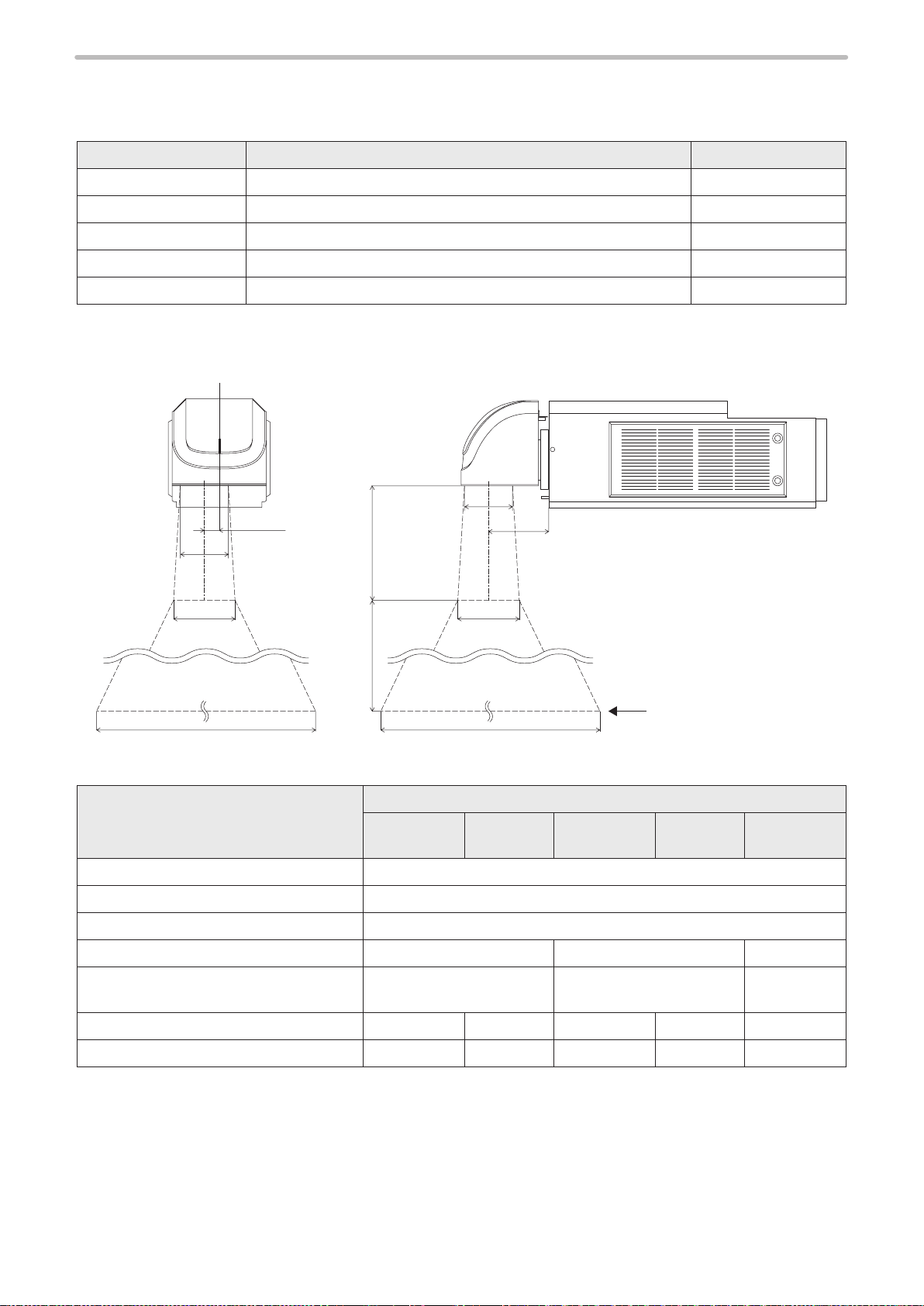
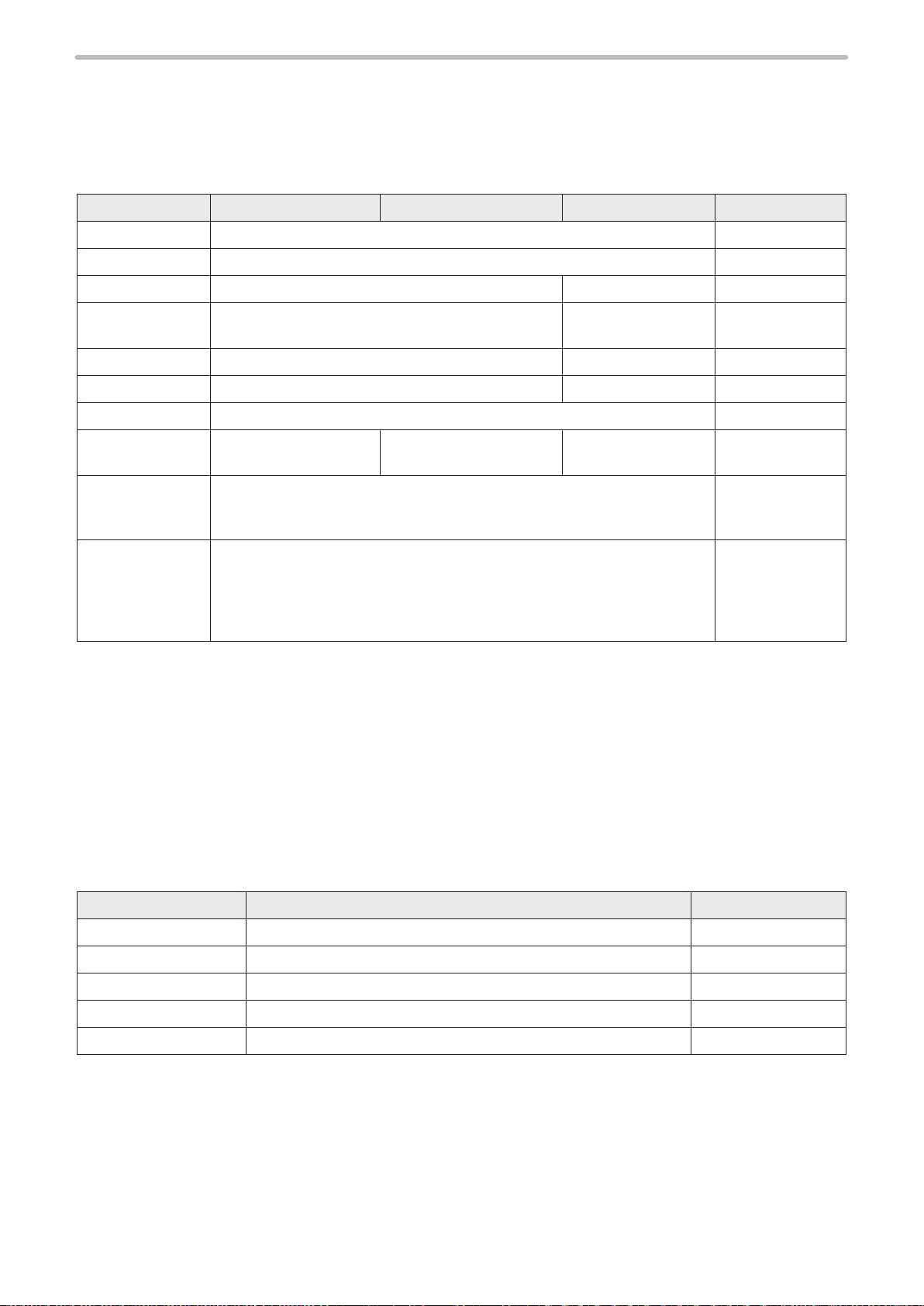
Radiation range of LP-400 Series Standard Head Model
⿎
*1
E
C
A
D
F
1mW -
C
B
E
NOHD
Unit: mm
Model
Specied Point
A : Center Position of Laser Emission Port 28
B : Center Position of Laser Emission Port 113
C : Diameter of Laser Emission Port
D : Working distance 185 111 262
E : Laser Radiation Range at Working
distance
F : NOHD 4900 2500 3000 1500 6900
G : Laser Radiation Range at NOHD
LP-430U
LP-420S9U
3500
φ
φ
160
LP-410U
1900
φ
LP-431U
LP-421S9U
66
φ
1600
φ
φ
80
LP-411U
800
φ
LP-435U
LP-425S9U
230
φ
5300
φ
21
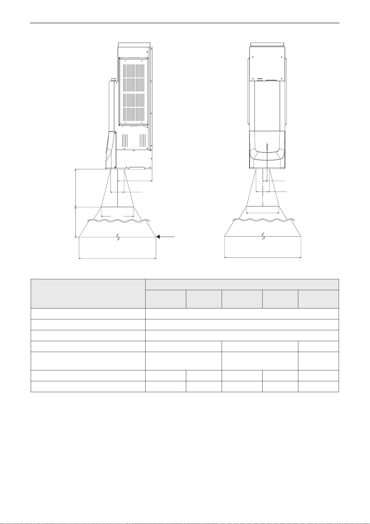
Radiation range of LP-400 Series Tower Head Model
ME-LP400V-OP-6
⿎
B
D
E
F
G
Specied Point
A : Center Position of Laser Emission Port 22
B : Center Position of Laser Emission Port 170.5
C : Diameter of Laser Emission Port
D : Working distance 185 111 262
E : Laser Radiation Range at Working
distance
C
LP-430TU
LP-420S9TU
φ
NOHD
160
LP-410TU
Model
LP-431TU
LP-421S9TU
66
φ
φ
80
E
G
LP-411TU
A
C
Unit: mm
LP-435TU
LP-425S9TU
230
φ
22
F : NOHD 4900 2500 3000 1500 6900
G : Laser Radiation Range at NOHD
φ
3500
φ
1900
φ
1600
φ
800
φ
5300
Radiation Information [LP-V/LP-W Series]
ME-LP400V-OP-6
Marking Laser (Class 4)
⿎
Class 4 laser refers to “Laser products for which intrabeam viewing and skin exposure is hazardous and for which the
viewing of diffuse reections may be hazardous. These lasers also often represent a re hazard.”
Model Name LP-V10U LP-V15U LP-W052U Remarks
Wavelength 1060nm Invisible beam
Laser Medium Yb:FIBER ―
Max. Output *1 40 W 7.5 W ―
Mode of Operation Pulsed
Pulse Cycle 10 μs to 50 μs ― ―
Pulse Width *2 1 ns to 1000 ns ― ―
Class 4 ―
NOHD *3 35.8 m 65.9 m 21 m
MPE *4 50 W/m
NHZ represents the area where the amount of beam irradiance or radiant
exposure exceeds the maximum permissible exposure to eyes. It is equal of
NHZ
*1 : The maximum output power means the maximum value of output that can be output from a laser oscillator itself.
Refer to “1-3 Specication” (P.36) for details of average output.
*2 : The pulse width means the available output range from the laser oscillator itself.
*3 : “NOHD” means the distance that the area where the amount of beam irradiance or radiant exposure becomes equal
to the maximum permissible exposure to eyes.
*4 : MPE in this table is a value calculated with exposure time set to 10 seconds.
NOHD at a maximum.
NHZ varies depending on the reectance or surface condition of works.
Please calculate it based on the actual working environment.
2
CW
(continuous wave)
―
Nominal ocular
hazard distance
Maximum
Permissible
Exposure
Nominal hazard
zone
Guide Laser and Pointer (Class 2)
⿎
The laser classied into the Class 2 refers to “Laser products that emit visible radiation in the wavelength range from 400
nm to 700 nm that are safe for momentary exposures but can be hazardous for deliberate staring into the beam.”
Model Name LP-V/LP-W series Remarks
Wavelength 655nm Visible beam
Laser Medium Semiconductor Laser -
Max. Output *1 1mW -
Mode of Operation CW (continuous wave) -
Class 2 -
*1 : Sum of the guide laser and pointer values.
23
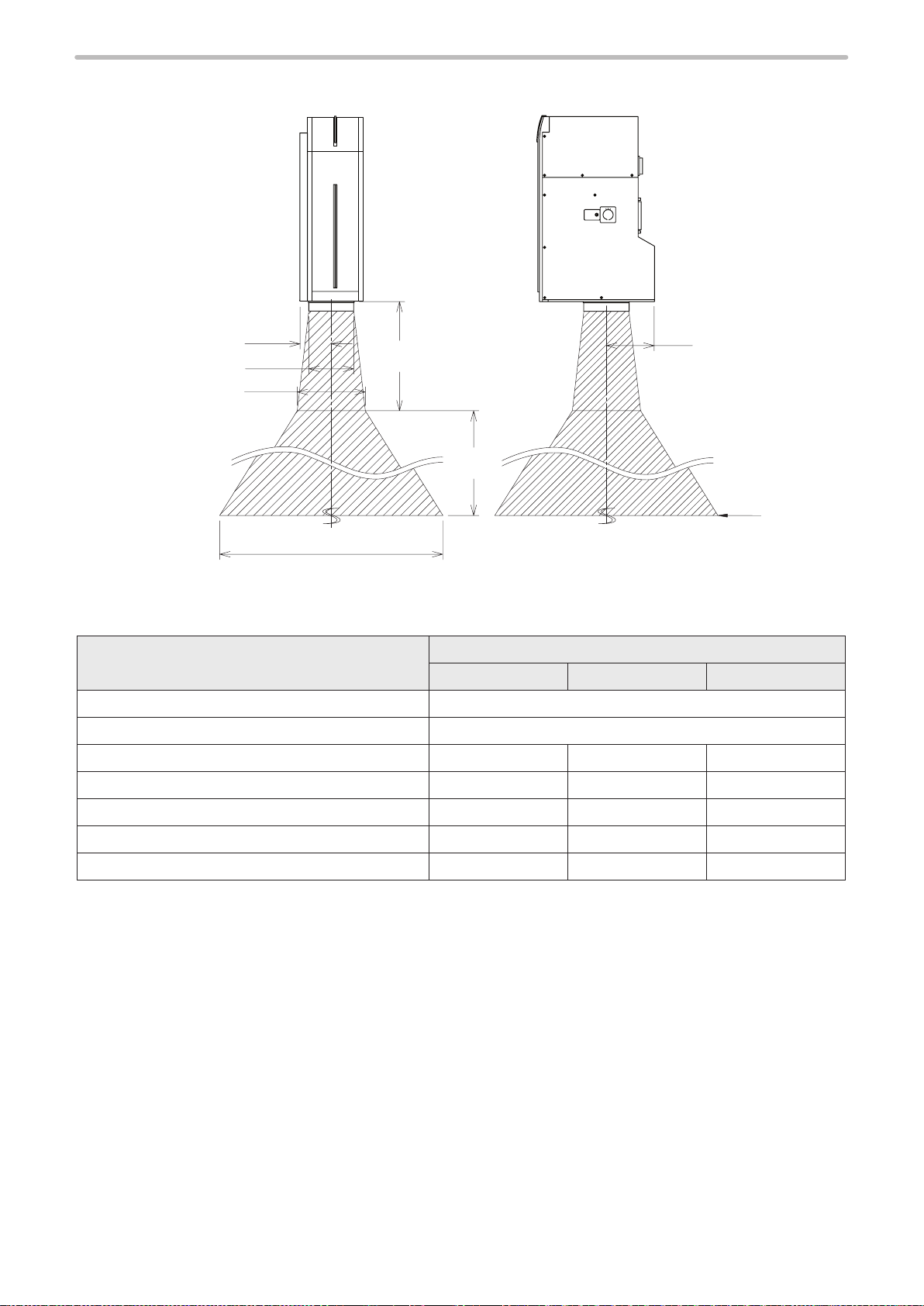
Radiation range of LP-V / LP-W Series
ME-LP400V-OP-6
⿎
A
C
E
G
Specied Point
A : Center Position of Laser Emission Port 60
B : Center Position of Laser Emission Port 91
C : Diameter of Laser Emission Port
D
F
Model
LP-V10U LP-V15U LP-W052U
87
φ
φ
106
B
NOHD
Unit: mm
87
φ
D : Working distance 190 350 127
E : Laser Radiation Range at Working distance
F : NOHD 35800 65900 21000
G : Laser Radiation Range at NOHD
φ
φ
130
19200
φ
φ
230
37700
φ
φ
80
10000
24
Safety Protection Measures for Users
WARNING
ME-LP400V-OP-6
This product falls into Class 4 laser (marking laser) and Class 2 laser (guide laser) based on the classications of the Safety
of laser products by IEC60825-1 / FDA standards 21 CFR 1040.10 and 1040.11 / JIS C 6802.
Perform the safety protection measure shown below before using the system.
For more detail instruction, refer to each of the standard.
Moreover, there is a case where related regulations are set for using the laser product depending on a country and a
region. When use this product, follow these regulations.
Construction of interlock system
⿎
For operating this product, construct the protective enclosure enclosing the range of the laser radiation for protecting
the exposure caused by the reection of the laser radiation from the marking object or the surrounding objects, and also
construct the interlock system at the same time. Additionally, install the control part that is not to exposure to the laser
beam. Refer to “Construction of Interlock System” (P.31) for details.
• Construct a system for re-pumping the laser manually as safety protection
measures after stop of the laser radiation.
Wearing protective goggles
⿎
For protection eyes of an operator, make it mandatory to wear goggles against laser beam in the laser control area.
Use the laser protective goggles or glasses applicable for wavelength of the specic to the marking laser and appropriate to
working conditions.
For this product, use the laser protective goggles or glasses which meet the following requirements.
• For LP-400 series: The goggles or glasses that have Optical Density (OD) of more than 6 at wavelength 9300 nm to
10600 nm (9.3 to 10.6 micrometers).
• For LP-V/LP-W series: The goggles or glasses that have Optical Density (OD) of more than 6 at wavelength 1060 nm to
1070 nm (1.06 to 1.07 micrometers).
• Through the goggles or glasses, the laser radiation indicator should be recognized.
• ANSI Z136 and CE certied laser safety goggles or glasses
The protective goggles can momentarily protect the eyes against the scattered beam. Never look at the direct beam or
reected beam even when the goggles are used.
Protective enclosure
⿎
In order to prevent exposure to laser beam accidentally reected from the marking object or from its circumferential areas,
place a protective enclosure so that it can enclose the area in the range of laser radiation.
Construct the enclosure with proper reectance, durability and thermal resistance materials that does not transmit a
wavelength of the marking laser.
Recommended material for the enclosures:
• For LP-400 series: Metals such as iron, aluminum, or stainless steel, or acrylic resins. For acrylic plate, its thickness
should be more than 3mm and it is recommended to use the plate that has a color to reduce the secondary radiation
beam such as spark during the lasing.
• For LP-V / LP-W series: Metals such as iron, aluminum, or stainless steel.
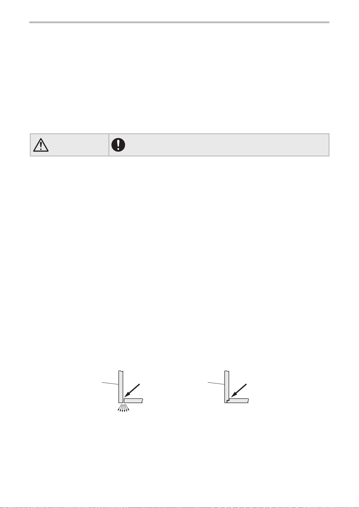
Design the enclosure not to leak the laser beam from the joint parts.
Example of the joint parts:
Enclosure Enclosure
Laser
Danger of laser exposures
Laser Laser
Example of recommended joint design
25

Key control
WARNING
ME-LP400V-OP-6
⿎
In order to avoid the operation of the system by the person without authorization and allowance, the laser safety manager
must remove key and keep it when not in use.
• It is obligated by IEC/FDA/JIS that laser products shall incorporate a keyactuated master control. Actuation of this product is basically controlled by
the key switch located on the front of the controller. However, in considering
situations when the laser marker is operating as a part of a larger system, the
laser marker turns on if the key switch is already in ON position, and power is
supplied. In this case, be sure that the external system controls the operation
of the laser marker with a key-actuated master control.
Power failure recovery
⿎
For power failure occurs on the laser marker, construct a laser re-pumping system by manual operation for safety.
Radiation direction of laser beam
⿎
To assure safety, be sure to place the protective enclosure.
Measures should be taken so that the direction of laser radiation can be seen and checked by others as well as an operator.
(The warning labels are adhered to this product with shipment. Do not peel them off.)
Termination of laser beam
⿎
Terminate a laser beam path within the marking range by using a ame-resistant object. Do not use the specular object for
the termination.
Path of laser beam
⿎
The laser beam path should be set avoiding the eye level of workers at both sitting and standing time.
Illumination
⿎
Make the area surrounding the laser marker well-lighted as much as possible.
Because the pupils are contracted in the well-lit place, it reduces the risk to the eyes.
For LP-V/LP-W series, do not expose strong beam to the laser radiation exit. Failure to do so could cause the malfunction
of the power check monitor.
Protective clothing
⿎
Exposure of the skin to the laser beam may cause a skin burn. Exposure of the clothing to the laser beam may cause
burning as well.
Wear the clothing which can minimize the exposure of the skin to the laser and which is ame-resistant.
Appointment of laser safety manager
⿎
By appointing a laser safety manager*, ensure that the laser product is handled safety.
Items that the laser safety manager has to manage and execute are as follows:
• Implementation of countermeasure against the prevention of disability from laser beam
• Setting and management of laser management area
• Management of laser device and system and key
• Inspection and maintenance of laser device, and storage of records
• Inspection, maintenance, and check the status of use of protective equipment
• Execution of safety education and training for users for the laser
* Responsible person having adequate knowledge of laser hazard evaluation and competence in protection against laser
hazards
26

Safety Functions on Laser Marker
WARNING
ME-LP400V-OP-6
This laser marker has the functions shown below for safety measures.
Use these functions properly and operate the laser marker system safely.
Head
LP-400 Series Standard Head Model
1
4
2
3
LP-400 Series Tower Head Model
1
2
5
5
LP-V/LP-W series
2
1
3
4
5
1 Internal Shutter : This is a shutter inside the head. The emission of laser beam is stopped by closing the
internal shutter.
2
Laser Radiation
Indicator
: The operations of the laser radiation indicator are as follows:
3
4
4
Laser in non-pumped state Lights-out
Laser pumping is in progress (uncompleted) and internal shutter closed Blue ashing
Laser pumping is in progress (uncompleted) and internal shutter opened Purple ashing *1
Being in laser pumped state and internal shutter closed Blue lighted-up
Being in laser pumped state and internal shutter opened Purple lighted-up
Being in laser emitting Red lighted-up
*1 : This status is shown only by LP-V and LP-W series.
• If the laser emission indicator on the laser marker is placed out of the
sight of operators, place the external indicator light or warning lamp on the
immediately apparent place on the system.
27
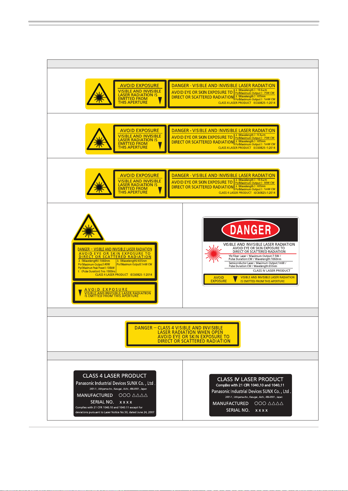
3 to 5 Labels : The labels shown below are afxed to the laser marker.
ME-LP400V-OP-6
(Contents of the labels vary depending on model.)
If the head is placed out of the sight of operators, place the attached warning label on
the immediately apparent place on the system.
3 Warning / Explanatory / Aperture Label
LP-430(T)U-A / LP-431(T)U-A / LP-435(T)U-A / LP-430(T)U-C / LP-431(T)U-C / LP-435(T)U-C
LP-420S9(T)U-A / LP-421S9(T)U-A / LP- 425S9(T)U-A / LP-420S9(T)U-C / LP- 421S9(T)U-C / LP-425S9(T)U-C
LP-410(T)U-A / LP-411(T)U-A / LP-410(T)U-C / LP- 411(T)U-C
LP-V10U-A / LP-V15U-A / LP-V10U-C / LP-V15U-C LP-W052U-A
4 Protective Housing Label
5 Certication and Identication Label for FDA compliant model
LP-4xx(T)U-A / LP-4xxS9(T)U-A / LP-VxxU-A
LP-W052U-A
28
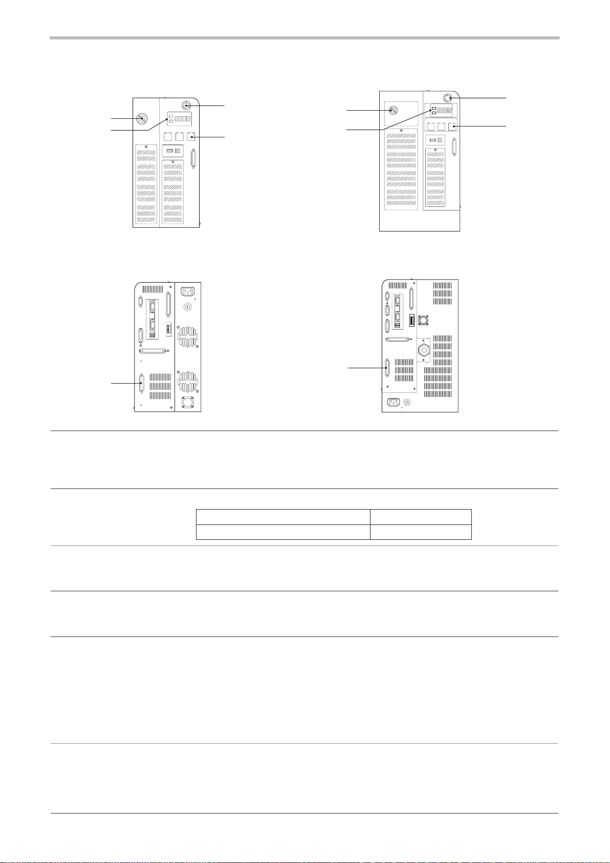
Controller
ME-LP400V-OP-6
LP-400 Series
Front
3
1
2
Rear Rear
4
1
2
LP-V/LP-W Series
Front
3
4
5, 6
5, 6
1 Key Switch : This is the key switch for starting up the laser marker.
Only when the key switch is turned OFF (in O position), the key can be pulled out.
When the laser marker is not in use, the key should be in safekeeping by a laser safety
manager.
2
Laser Radiation
Indicator
3 Emergency Stop
Switch
4 Alarm Reset Switch : This switch is used to reset the system when an alarm generates. LED lights up in blue
5 Laser Stop Input
Emergency Stop
Input (I/O terminal)
: The operations of the laser radiation indicator are as follows:
Non-emitting state Lights-out
Being in laser emitting Orange lighted-up
: This switch is used to forcibly stop the laser pumping.
Push this switch at emergency or to stop the laser radiation. Turn the switch to the
direction of the arrow to release it.
when an alarm generates. Release the cause of alarm and press this switch. Alarm
can be reset from the input/output terminal, console (optional) or monitor screen.
: The I/O terminal equips Laser Stop input and Emergency Stop input. Opening either of
the signals or making its voltage level Low disables the laser emission. Construct the
safety system by connecting it to the door or switch of the equipment.
Operation when Laser stop is released :
• When laser is not radiating: Close the internal shutter.
• When laser is radiating: Close the internal shutter and turn Laser pumping OFF.
Operation when Emergency stop is released :
• Close the internal shutter and turn Laser pumping OFF.
6 Input/Output Terminal : The terminal equips various signals, such as shutter input, marking output, mark end
output, ready output etc.
Use these signals for the purpose of controlling other external safety devices, such as
an indicating lamp.
Refer to the External control manual for details.
29

Laser Marker Operation at Inputting the Safety Functions
ME-LP400V-OP-6
⿎
Safety Function Laser Marker Operation Release Method
Laser Stop in I/O terminal *1
CLOSE to OPEN
Emergency Stop in I/O
terminal
CLOSE to OPEN
Push Emergency Stop
Switch
*1 : The operation behavior of Laser Stop varies depending on the laser emission ON / OFF status.
(Inputting Emergency Stop in I/O terminal and Emergency Stop Switch, regardless laser emission ON/OFF status, the
laser is powered OFF and the shutter is closed.)
*2 : Under the non-remote mode in closing shutter status (non-emitting status), the error does not occur.
Laser stop input during laser emission
• Laser Pumping: OFF
• Internal Shutter: CLOSE
• Status: Alarm E011
Laser stop input at non-emitting with opened shutter
• Laser Pumping: Hold ON
• Internal Shutter: CLOSE
• Status: Warning E811
• Laser Pumping: OFF
• Internal Shutter: CLOSE
• Status: Alarm E004 *2
• Laser Pumping: OFF
• Internal Shutter: CLOSE
• Status: Alarm E002 *2
Close Laser Stop and input alarm
reset.
Close Laser Stop.
Close Emergency Stop and input
alarm reset.
Push emergency stop switch and
input alarm reset.
30
 Loading...