

Panasonic LP-310, LP-310-B, LP-310-A, LP-310-C Operation Manual
表紙~はじめに
CO2 Laser Marker
LP-300 SERIES
Operation Manual
ME-LP300-OP-12 No.9000-0062-20V
2018.5
panasonic.net/id/pidsx/global
Preface
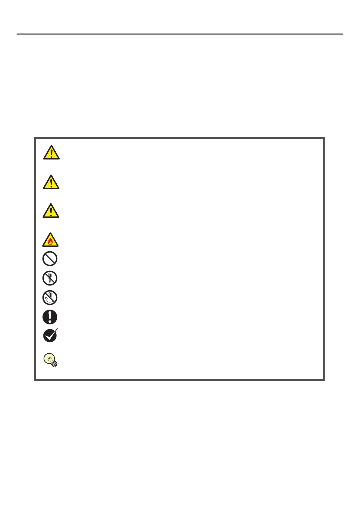
“DANGER” denotes hazards that could result in serious personnel injury or death when
handling error occurs, and emergency precautions (urgency level) when any dangerous
situation causes.
“WARNING” denotes hazards that could result in serious personnel injury or death when
handling error occurs.
“CAUTION” denotes that any damages on personnels or objects could result in when
handling error occurs.
This symbol denotes the possibility of fire.
This symbol denotes a general prohibition notice.
This symbol denotes the prohibition of disassembling the product.
This symbol denotes the prohibition of touching the specified place.
This symbol denotes a general action which operators must take.
“CHECK” denotes any instructions or precautions for using this product.
“REFERENCE” denotes any hints for operation, detail explanations, or references.
DANGER
W ARNING
CAUTION
REFERENCE
Thank you for purchasing Laser Marker .
For full use of this laser marker safely and properly, please read this manual carefully.
This system has been strictly checked and tested prior to its delivery, however, please make sure that this
system operates properly before using it.
In case that the system becomes damaged or does not operate as specified in this manual, contact the shop
you bought it or our sales office.
■ Symbol Indications
This manual uses a variety of symbols to explain safety precautions, instructions, and references for operating
personnel.
Before reading this manual, fully understand the contents of these indications.
■ Note
1. Contents of this manual will be changed without notice.
2. This manual and software must not be partially or totally copied or revised.
3. If there are any questions, mistakes, or comments in this manual, please notify us.
4. Please remind that we do not have responsibility of any results of operations in regardless of the above 3
clauses.
2

■ General Terms And Conditions
Please read this document carefully with respect to our product warranty policy before using our Panasonic Industrial
Devices SUNX products (“Products”). If you have any questions or comments regarding do's and don'ts of the Products,
please consult your local Panasonic Industrial Devices SUNX authorized dealer for the correct use and application of the
Products.
1. PRODUCT MODIFICATIONS & DISCONTINUANCE:
Panasonic Industrial Devices SUNX expressly reserves the right to modify, including the right to discontinue, any of
the Products, prior to their order, from time to time without notice.
2. WARRANTIES:
(1) Subject to the exclusions stated in 3 (EXCLUSIONS) herein below, Panasonic Industrial Devices SUNX warrants
the Products to be free of defects in material and workmanship for a period of one (1) year from the date of
shipment under normal usage in environments commonly found in manufacturing industry.
(2) Any Products found to be defective must be shipped to Panasonic Industrial Devices SUNX with all shipping
costs paid by Purchaser for inspection and examination. Upon examination by Panasonic Industrial Devices
SUNX, Panasonic Industrial Devices SUNX will, at its sole discretion, repair or replace at no charge, or refund
3. EXCLUSIONS:
4. DISCLAIMERS:
5. CAUTIONS FOR SAFE USE:
6. EXPORT CONTROL LAWS:
7. PURCHASER'S TRANSFER OBLIGATIONS:
the purchaser price of, any Products found to be defective.
(1) This warranty does not apply to defects resulting from any cause:
(i) which was due to abuse, misuse, mishandling, improper installation, improper interfacing, or improper repair
by Purchaser;
(ii) which was due to unauthorized modification by Purchaser, in part or in whole, whether in structure,
performance or specification;
(iii)which was not discoverable by a person with the state-of-the-art scientific and technical knowledge at the time
of manufacture;
(iv)which was due to an operation or use by Purchaser outside of the limits of operation or environment specified
by Panasonic Industrial Devices SUNX;
(v) which was due to Force Majeure; and
(vi)which was due to any use or application expressly discouraged by Panasonic Industrial Devices SUNX in 5
(CAUTIONS FOR SAFE USE) hereunder.
(2) This warranty extends only to the first purchaser for application, and is not transferable to any person or entity
which purchased from such purchaser for application.
(1) Panasonic Industrial Devices SUNX's sole obligation and liability under this warranty is limited to the repair or
replacement, or refund of the purchase price, of a defective Product, at Panasonic Industrial Devices SUNX's
option.
(2) THE REPAIR, REPLACEMENT, OR REFUND IS THE EXCLUSIVE REMEDY OF THE PURCHASER, AND ALL
OTHER WARRANTIES, EXPRESS OR IMPLIED, INCLUDING, WITHOUT LIMITATION, THE WARRANTIES OF
MERCHANTABILITY, FITNESS FOR A PARTICULAR PURPOSE, AND NON-INFRINGEMENT OF
PROPRIETARY RIGHTS, ARE HEREBY EXPRESSLY DISCLAIMED. IN NO EVENT SHALL Panasonic Industrial Devices SUNX AND ITS AFFILIATED ENTITIES BE LIABLE FOR DAMAGES IN EXCESS OF THE
PURCHASE PRICE OF THE PRODUCTS, OR FOR ANY INDIRECT, INCIDENTAL, SPECIAL OR
CONSEQUENTIAL DAMAGES OF ANY KIND, OR ANY DAMAGES RESULTING FROM LOSS OF USE,
BUSINESS INTERRUPTION, LOSS OF INFORMATION, LOSS OR INACCURACY Of DATA, LOSS OF
PROFITS, LOSS OF SAVINGS, THE COST OF PROCUREMENT OF SUBSTITUTED GOODS, SERVICES OR
TECHNOLOGIES, OR FOR ANY MATTER ARISING OUT OF OR IN CONNECTION WITH THE USE OR
INABILITY TO USE THE PRODUCTS.
(1) It is Purchaser's sole responsibility to ascertain the fitness and suitability of the Products for any particular
application, as well as to abide by Purchaser's applicable local laws and regulations, if any.
(2) In incorporating the Products to any equipment, facilities or systems, it is highly recommended to employ fail-safe
designs, including but not limited to a redundant design, flame propagation prevention design, and malfunction
prevention design so as not to cause any risk of bodily injury, fire accident, or social damage due to any failure of
such equipment, facilities or systems,
(3) The Products are each intended for use only in environments commonly found in manufacturing industry, and,
unless expressly allowed in this manual, specification or otherwise, shall not be used in, or incorporated into, any
equipment, facilities or systems, such as those:
(i) which are used for the protection of human life or body parts;
(ii) which are used outdoors or in environments subject to any likelihood of chemical contamination or
electromagnetic influence;
(iii)which are likely to be used beyond the limits of operations or environments specified by Panasonic Industrial
Devices SUNX in this manual or otherwise;
(iv)which may cause risk to life or property, such as nuclear energy control equipment, transportation equipment
(whether on rail or land, or in air or at sea), and medical equipment;
(v) which otherwise require a high level of safety performance similar to that required in those equipment,
facilities or systems as listed in (i) through (iv) above.
In some jurisdictions, the Products may be subject to local export laws and regulations. If any diversion or re-export
is to be made, Purchaser is advised to abide by such local export laws and regulations, if any, at its own
responsibility.
If Purchaser resell or deliver the Products to a third party, Purchaser must provide such third party with a copy of this
document, all specifications, manuals, catalogs, leaflets and written information of any kind provided to Purchaser by
Panasonic Industrial Devices SUNX or its authorized local representative from time to time regarding the Products.
3

■ Trademarks
• Window is a registered trademark or trademark of U.S.A. Microsoft Corporation in U.S.A and other
countries.
All other product names and companies provided in this manual are trademarks or registered trademarks
of their respective companies.
■ Warranty of Product
1. Warranty Period
• The warranty period is one year after delivery of the system to the ordered place by a purchaser.
2. Warranty Limitation
• When a failure is produced by a supplier, exchange of the failure parts of the system, or repair of it is
performed in the responsibility of the supplier.
However, if failure of the system has resulted from the following reasons, the warranty is void.
1) Any fault or defect caused by inadequate handling or abnormal use.
2) Any fault or defect caused by the other reasons than the supplier's fault.
3) Any fault or defect caused by modification or repair of the system by any others than the suppliers.
4) Any fault or defect caused by force majeure.
Note that the warranties set forth herein cover faults of defects of delivered products alone and do not
cover any damage induced by faults or defects of delivered products.
4

MEMO
5
Cautions in Handling Laser Beam
1453300
78
ȭ80
ȭ43
200
16
ȭ1500
ȭ80
ȭ43
ȭ1500
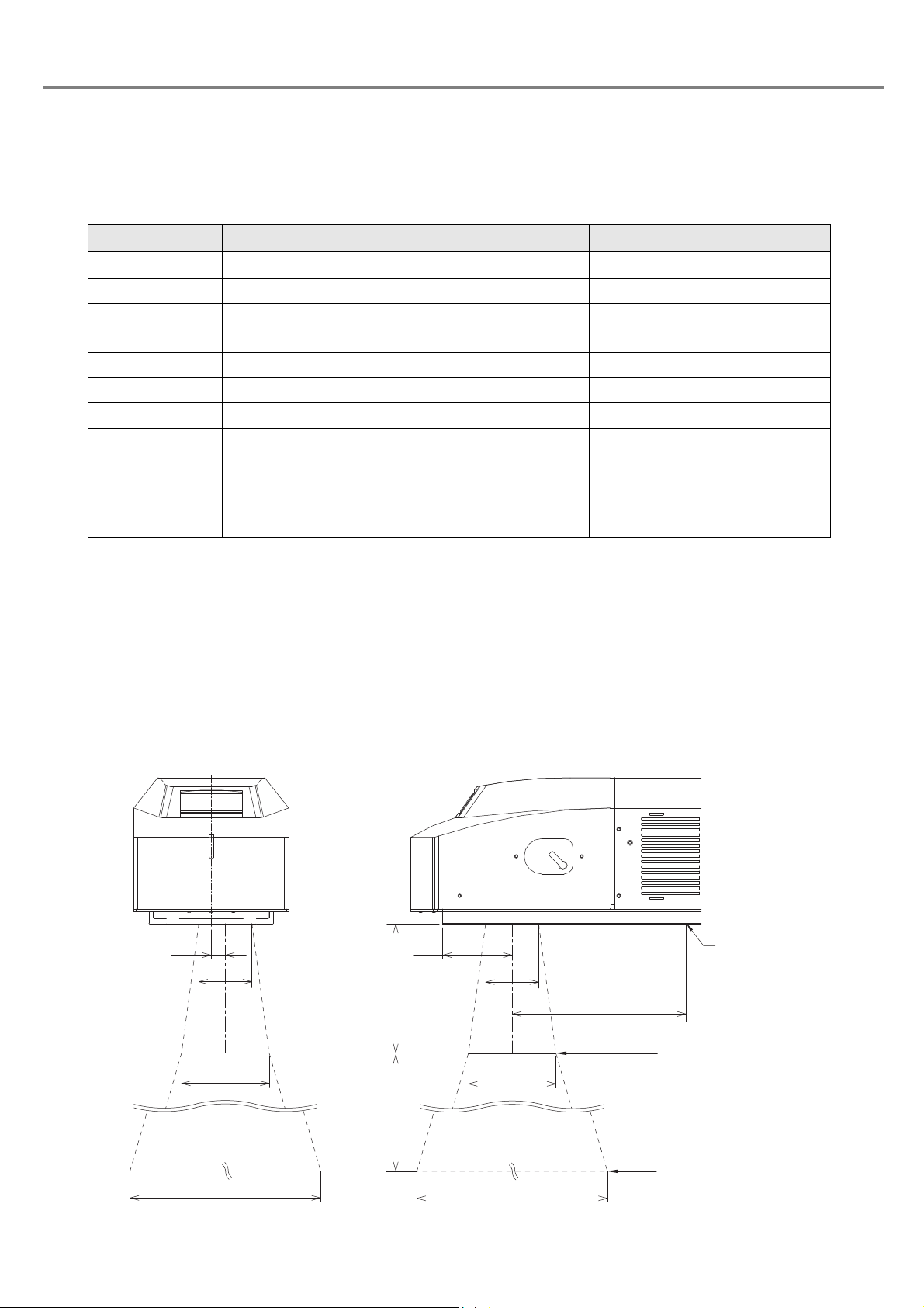
Screw Hole
Marking Position
NOHD Position
This product falls into Class 4 laser (marking laser) and Class 2 laser (guide laser) based on the classifications of IEC608251 “Safety of laser products”.
Class 4 laser refers to “Laser products for which intrabeam viewing and skin exposure is hazardous and for which the viewing
of diffuse reflections may be hazardous. These lasers also often represent a fire hazard.”
Perform the safety protection measure before using the system. Refer to “Safety Protection Measures” (P.8) for details.
Item Specification Remarks
Wave Length
Laser Medium CO
Max. Output *1 30W
Laser frequency 10kHz
Class 4
NOHD *2 3.3m Normal ocular hazard distance
MPE*3
NHZ represents the area where the amount of beam irradiance or radiant expposure exceeds the maximum per-
NHZ
missible exposure to eyes. It is equal to the value of
NOHD at a maximum.
NHZ varies depending on the reflectance or surface condition of works. Please calculate it based on the actual
working environment.
10.6μm
2
1000W/m
2
Maximum permissible exposure
Invisible beam
-
-
-
-
Nominal hazard zone
*1:The maximum output is the maximum value that the laser oscillator outputs laser beam.
This product is set to 10W as the average output of laser oscillator. Moreover, the optical power emitted from the laser
marker is decreased further.
*2:NOHD represents the distance from the light source of laser beam, where the amount of beam irradiance or radiant
expposure is equal to the maximum permissible exposure to eyes.
*3:
MPE means the assumed exposure duration for determination of the value.
The value colculated on 10 seconds.
■Laser Radiation Range
Unit: mm
6
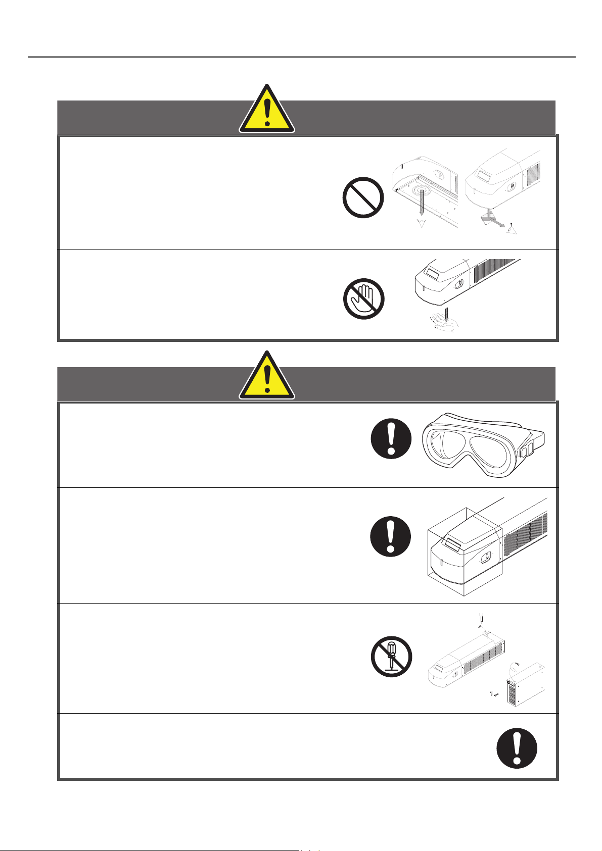
Never look at laser beam directly or
DANGER
WARNING
through lens.
Diffused reflected beam is also harmful.
laser does not enter into eye's retina,
CO
2
however, if it exposed to the eyes, it can
inflict severe corneal injuries.
Never touch laser beam. Be careful not
to touch laser beam with clothing as
well. Burning into deep skin might
result.
Wear laser protective goggles for operator's
eyes. The goggles should be used against
scattered beam, so avoid to direct beam or
reflection beam.
In order to prevent unexpected exposures
from object to be marked or its peripherals, set
protective enclosure which is made of acrylic
resin, glass, or metal to enclose the laser
radiation area.
Never disassemble the product.
Exposure of laser beam or electric shock by high-voltage
area might occur.
Read this manual thoroughly, and do not operate any other
methods except the instructions provided in this manual.
Exposure of laser beam might occur.
7
Safety Protection Measures
WARNING
Laser
Laser
Enclosure
Enclosure
Laser
Danger of laser exposures Example of recommended joint design
This product falls into Class 4 laser (marking laser) and Class 2 laser (guide laser) based on the classifications of the Safety
of laser products (JIS C 6802) / FDA standards 21 CFR 1040.10 and 1040.11/IEC60825-1.
Perform the safety protection measure shown below before using the system.
For more detail instruction, refer to each of the standard.
1. Construction of interlock system
In order to prevent exposure to laser beam accidentally reflected from the laser marking object or from its
circumferential areas, place a protective enclosure so that it can enclose the area in the range of laser
radiation, and construct the interlock mechanism in the system.
Additionally, install the control part that is not to exposure to the laser beam. Refer to “Construction Sample of
Interlock System” (P.14).
• For laser pumping is shut-off by interlock system, construct a laser re-pumping system by
manual operation for safety.
2. Wearing protective goggles
For protection eyes of an operator, make it mandatory to wear goggles against laser beam in the laser
controlled area.
For this product, use the laser protective goggles or glasses which meet the following requirements.
• The goggles or glasses that have Optical Density (OD) of more than 6 at wavelength 10600nm (10.6μm).
• Through the goggles or glasses, the laser radiation indicator should be recognized.
• ANSI Z136 and CE certified laser safety goggles or glasses
The protective goggles can momentarily protect the eyes against the scattered beam. Never look at the direct
beam or reflected beam even when the goggles are used.
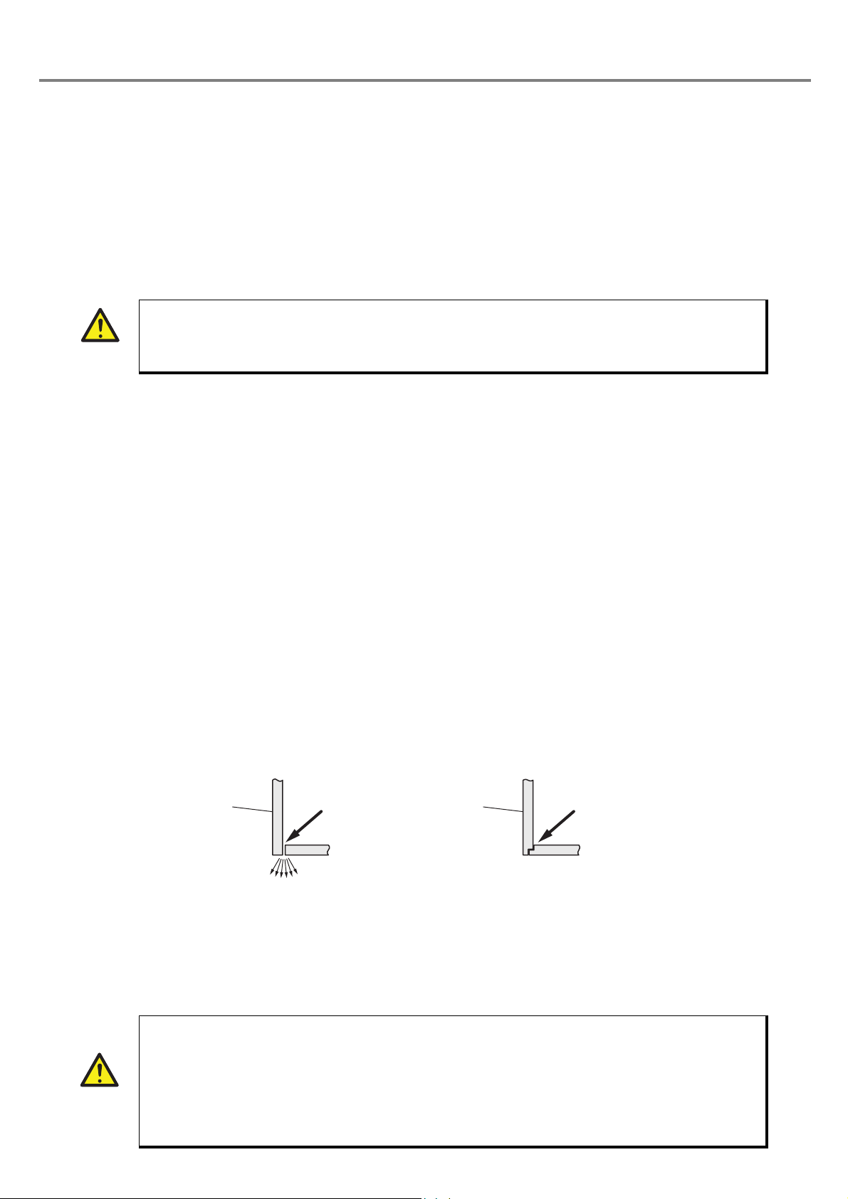
3. Protective enclosure
In order to prevent exposure to laser beam accidentally reflected from the laser marking object or from its
circumferential areas, place a protective enclosure so that it can enclose the area in the range of laser
radiation.
Construct the enclosure with proper reflectance, durability and thermal resistance materials that does not
transmit a wavelength of 10600 nm (10.6 μm).
Recommended materials for the enclosure: metals such as iron, aluminum, stainless steel, or acrylic resins.
For acrylic plate, its thickness should be more than 3 mm and it is recommended to use the plate that has a
color to reduce the secondary radiation beam such as spark during the lasing.
Design the enclosure not to leak the laser beam from the joint parts.
Example of the joint parts:
4. Key control
In order to avoid the operation of the system by the person without authorizatio and allowance, the laser
safety manager must remove key and keep it when not in use.
WARNING
8
• It is obligated by IEC/FDA/JIS that laser products shall incorporate a key-actuated master
control. Actuation of Our laser marker is basically controlled by the key switch located on the
front of the power supply box. However, in considering situations when the laser marker is
operating as a part of a larger system, the laser marker turns on if the key swith is already in ON
position, and power is supplied.
• In this case, be sure that the external system controls the operation of the laser marker with a
key-actuated master control.
5. Power failure recovery
REFERENCE
For power failure occurs on the laser marker, construct a laser re-pumping system by manual operation for
safety.
6. Radiation direction of laser beam
To assure safety, be sure to place the protective enclosure. Measures should be taken so that the direction of
laser radiation can be seen and checked by others as well as an operator. (The warning labels are adhered to
this product with shipment. Do not peel them off.)
7. Termination of laser beam
Terminate a laser beam path within the laser radiation range by using a flame-resistant object.
Do not use the specular object for the termination.
8. Path of laser beam
The laser beam path should be set avoiding the eye level of workers at both sitting and standing time.
9. Illumination
Make the area surrounding the laser marker well-lighted as much as possible. Because the pupils are
contracted in the well-lit place, it reduces the risk to the eyes.
10.Protective clothing
Exposure of the skin to the laser beam may cause a skin burn. Exposure of the clothing to the laser beam
may cause burning as well. Wear the clothing which can minimize the exposure of the skin to the laser and
which is flame-resistant.
11.Appointment of laser safety manager
By appointing a laser safety manager, ensure that the laser product is handled safety.
Items that the laser safety manager has to manage and execute are as follows:
1. Implementation of countermeasure against the prevention of disability from laser beam
2. Setting and management of laser management area
3. Management of laser device and system and key
4. Inspection and maintenance of laser device, and storage of records
5. Inspection, maintenance, and check the status of use of protective equipment
6. Execution of safety education and training for users for the laser
• There is a case where related regulations are set for using the laser product depending on a
country and a region. When use the laser marker, follow these regulations.
9
Functions for Safety Measures
132
REFERENCE
This laser marker has the functions shown below for safety measures.
■ Head Section
qew
1. Shutter Lever
• The laser can be radiated with the shutter opened, or it cannot be radiated with the shutter closed. Howevr, the
guide laser is available.
2. Laser Radiation Indicator
• The indicator lights in red for 0.5 seconds just after the power supply is turned ON. Then, it lights in blue
during trigger standby.
The color of the indicator is changed into red during marking.
• During excitation of the laser (approx. 15 seconds), the product is not ready for radiating laser.
3. File No./Error Code Display: FILE No./ERROR CODE
• The selected file No. is displayed. When an error occurs, the corresponding error code is displayed as well.
Refer to “5 Troubleshooting” (P.187) for details of error code.
10
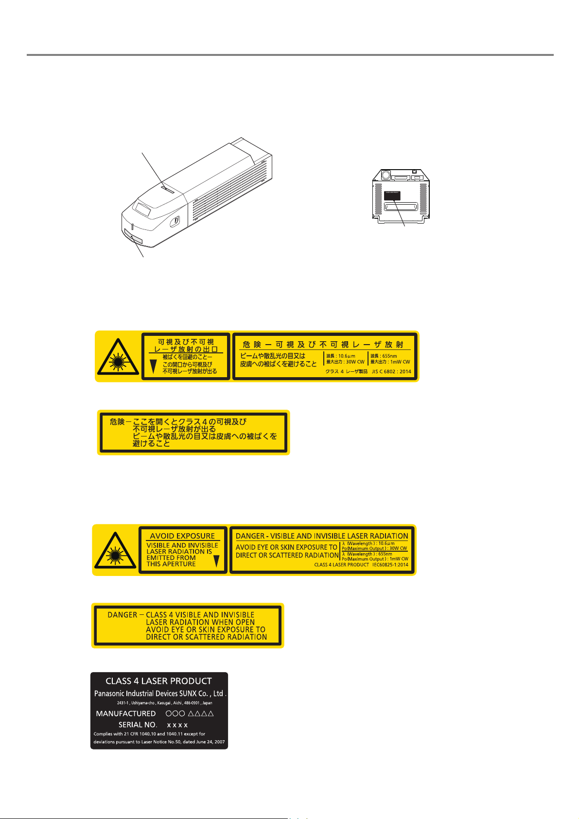
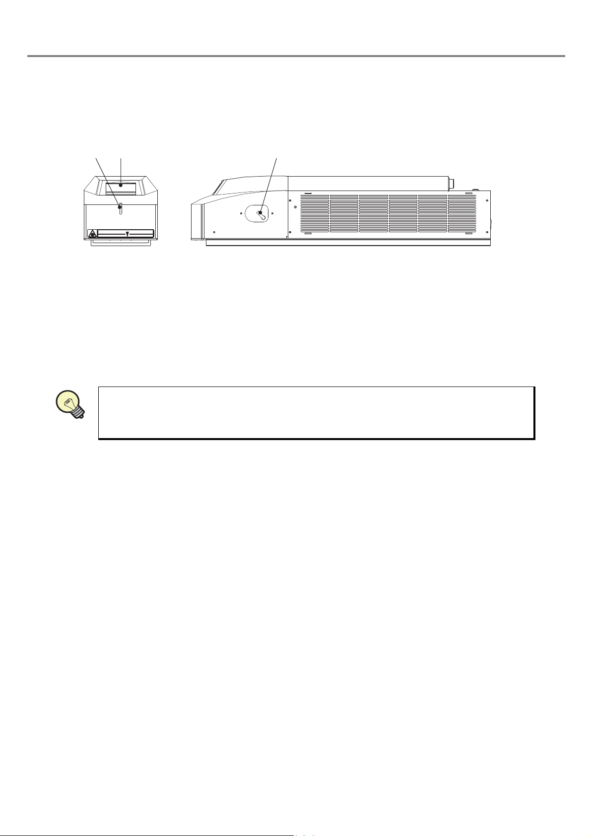
■ Labels
Warning, explanatory, aperture label
Protection Housing Label
Certification and identification label *1
Head rear side
A variety of labels shown below are affixed to the head part of the laser marker.
• LP-310
Warning, explanatory, aperture label
Protection Housing Label
• LP-310-A
• LP-310-C
Warning, explanatory, aperture label
Protection Housing Label
Certification and identification label *1
*1: Attached to LP-310-A only.
11
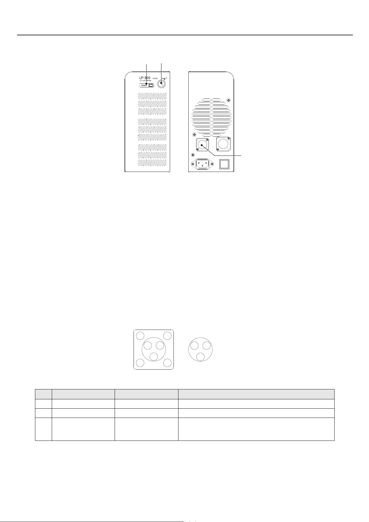
■ Power Supply BOX
1
3
2
On power supply
box side
On user side
1. Power Supply Display
• When turning ON the key switch, this indicator flashes in green.
When the system starts up and runs completely, the indicator switches into lighting status.
2. Key Switch
• This key switch is used to start the laser marker system. While the switch is ON, the key cannot be
removed, however, while it is OFF, the key can be removed. Remove the key while not using the laser
marker, and maintain and control the key by the safety controller without fail.
• Since the ON/OFF operation of the key switch makes a load to the laser marker, do not turn OFF the power until
completing the start of the system. Besides, leave an interval for at least 5 seconds from turning OFF the power
to turning ON the power again.
3. Interlock Connector
• This interlock connector controls the deactivating/activating status of the laser. It enables to construct the
interlock system.
■ Interlock Connector
•
This product is equipped with the interlock connector to the power supply box. Use this interlock connector
11
22
33
Interlock Connector: SRCN6A13-3P Japan Aviation Electronics Industry,Ltd.
Connector on the body side: SRCN2A13-3S Japan Aviation Electronics Industry,Ltd.
No. Signal Name Name Content
1 INTERLOCK COM. Interlock Common Common for interlock
2 N.C. - Do not connect anything.
3 INTERLOCK Interlock Input When connected to INTERLOCK COM., the product is ready
* Keep the OPEN state between INTERLOCK (Pin 3 ) and INTERLOCK COM. (Pin 1) for 1 sec. or more when they are
oepned. If the OPEN state is too short, the laser tube error (E23) may occurs.
for laser radiation. When the product is in open status, the
laser radiation is stopped.
.
12

■ I/O Connector
Laser Radiation Stop Input
Pin 4
CHECK
IN COM.
OUT COM.
LASER STOP
㸨
䠍
䠍
㻟 㻞
㻝㻠
㻝㻡
㻝㻤
㻝㻥
㻞㻜
㻞㻡
㻝㻟
䠏
䠎
䠐
㻡
㻣
㻢
㻤
1. INTERLOCK COM.
3. INTERLOCK
1. +12V
2. 0V
3. TRIG. IN
4. LASER STOP
14. IN COM.
15. OUT COM.
Interlock Input Terminal
(Power Supply BOX)
To Emergency
Stop Switch
I/O Connector
To Sensor
To Manual Door
0V
12V
• This product is equipped with the laser radiation stop input in the I/O connector.
Laser Marker Side Connector Type : Female D-sub 25 pin
User Side Connector Type : Male D-sub 25 pin *
* As a user side connector, following items are attached to this product.
[Attached item] User Side Connector : HDBB-25P (Hirose Electoric Co., Ltd.)
[Attached item] User Side Connector Cover : HDB-CTF (Hirose Electoric Co., Ltd.)
Laser Radiation Stop Input
• When changing the status of both laser radiation stop input (Pin 4) and output common (Pin 15) into open
status, the laser radiation is stopped and the marking is invalid.
When performing marking, connect both laser radiation stop input (Pin 4) and output common (Pin 15).
• This product is not activated by connecting (Pin 14), (Pin 15), and
(Pin 4) terminals of the I/O connector.
■ Connecting Sample (In case of operating only laser marker)
* Example when only the file No. 1 is used. To change the files, connect the pin No. 5 to 8 and 18 to 20 (D0 to D6) to the
external control device.
13
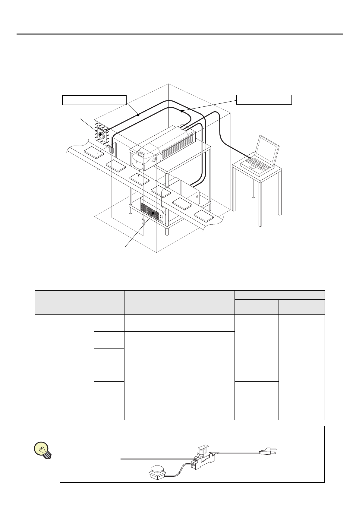
■ Construction Sample of Interlock System
㪘㪙㪚㪛
㪘㪙㪚㪛
㪘㪙㪚㪛
㪘㪙㪚㪛
Power Supply BOX
To Interlock Connector
I/O Connector at Head
To Laser Stop Input
Emergency Stop
Switch
Power Supply BOX
PC
REFERENCE
Relay
Emergency Stop Switch
AC Power Cable
• For operating this product, construct the protective enclosure enclosing the range of the laser radiation for
protecting the exposure caused by the reflection of the laser radiation from the object being marked or the
surrounding objects, and also construct the interlock system at the same time. The following figure shows
the construction sample of the interlock system.
■ Operation at Interlock Input
As shown in the table below, this product outputs error state by canceling the interlock input and also stops the
laser oscillation aiming for safety use of this product.
Laser Marker
Status
Normal
Operation
↓
Ready ON
Normal
↓
Head display
Error Code
after 15 sec.
Error Code
Interlock Input
Short-circuit
Short-circuit
Short-circuit
(Releasing during
marking operation)
Status of
Release
Release
↓
↓
Release
•
When primary AC power supply of the system is performed as a safety measure, process AC
power cable to set the switch as follows.
Shutter
OPEN
CLOSE OFF Blue
OPEN
CLOSE
OPEN
CLOSE Ready OFF
OPEN
Laser Oscillation
(Marking
Operation)
ON Red
Laser Radiation
Indicator
OFF Blue Alarm Status Error Code
OFF Blue
Ready OFF
after 15 sec.
ON
↓
OFF
Red
↓
Blue
Alarm Status
panel
File No.OFF Blue
↓
File No.
File No.
↓
14
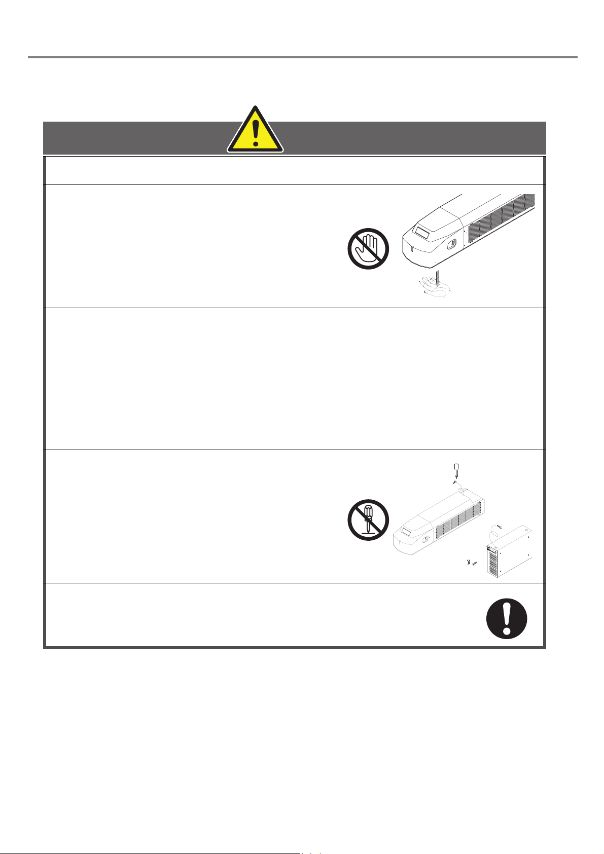
Cautions in Handling
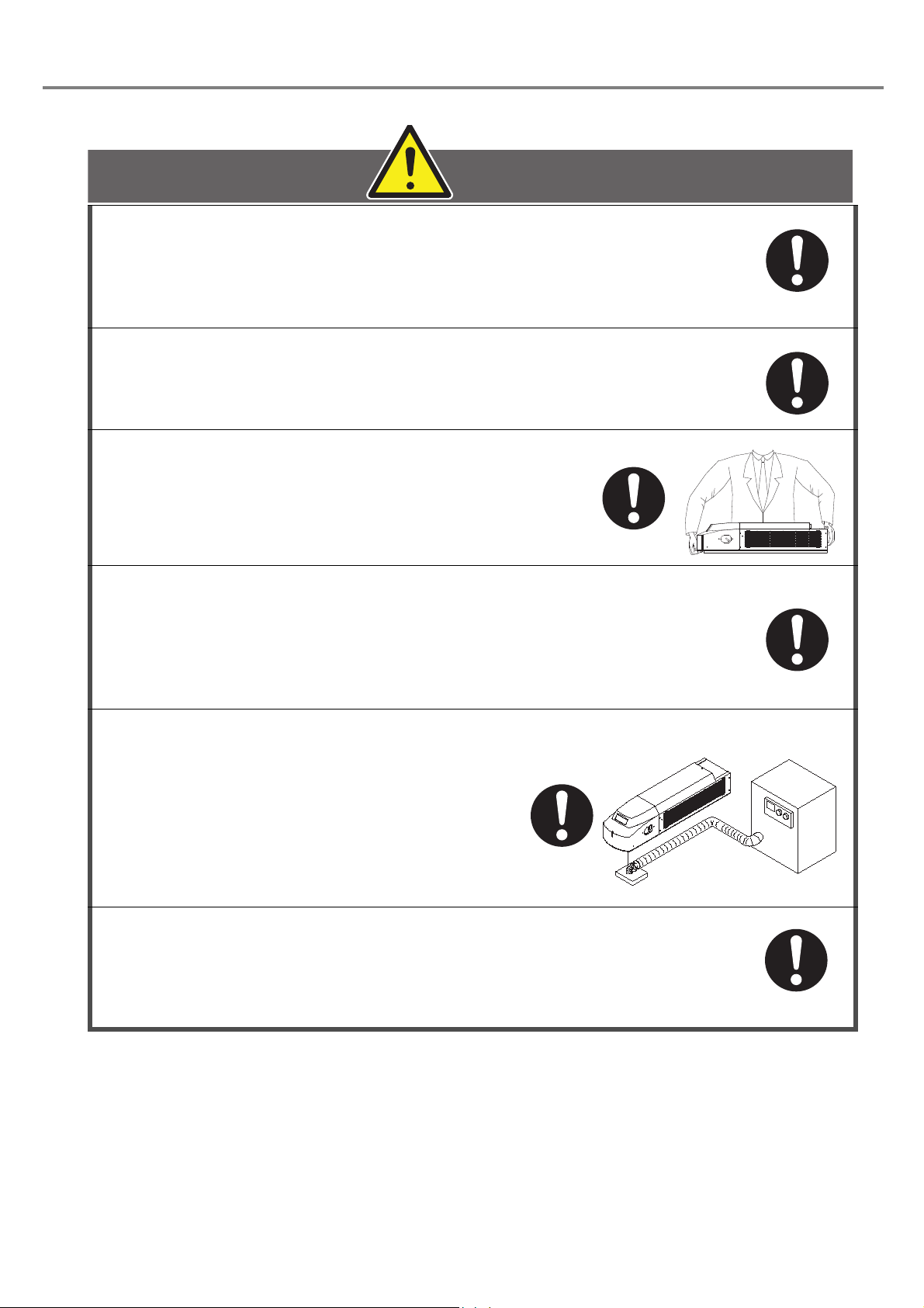
WARNING
■ Handling the System
This product has been developed/produced for industrial use only.
When using the system, do not touch laser
beam with any part of body, papers, or
clothing, etc
This product contains ZnSe (zinc selenide) in the lens mounted on the
laser radiation window. If the lens is damaged, care should be taken of the
.
following.
• In order to prevent from swallowing of flakes or particles, inhaling them, or adhering them to skin, be
sure to wear glove, mask and protective goggles.
• When disposing the lens, be sure to obey the disposing method prescribed in the regulations of user’s
region/countryfully. Do not dispose the lens with general industrial waste.
• Do not throw the lens into the fire.
• Do not soak the lens in acid and alkali.
Never disassemble the product. It can
result in exposure to laser radiation or an
electric shock due to high voltage.
In the event a failure occurs in the system, contact us.
After the power supply of laser marker is turned off, laser safety
manager must remove the system key and keep it.
15
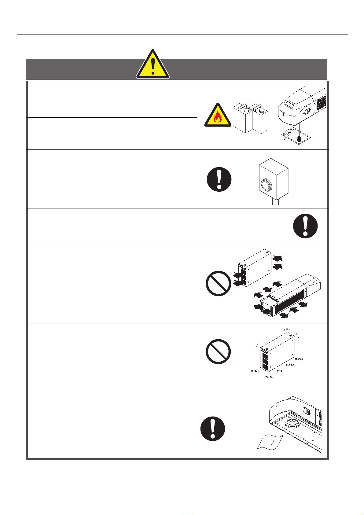
Use this product neither in inflammable
CAUTION
Gasoline
Thinner
Emergency Stop
Soft Cloth
gas, a dusty place nor the place of fire
strict prohibition. It might cause a fire.
Never put the object which is easy to
burn on near. It might causes a fire.
Construct an interlock systems such as a
function to stop laser radiation for the
maintenance door of the protective
enclosure
.
Use the product with the below environmental condition:
Ambient temperature: 0 to +40 degrees C (no condensation)
Ambient humidity : 35 to 85% (no condensation)
The air cooling system is used for this
product as a laser cooling system. Please
install not to bar the flow of air cooling.
Moreover, please do not install a heat
source in near, either.
Since this product includes precision
parts, please avoid vibration and use in a
place with any shocks. Printing quality
may deteriorate or the optical system may
be affected. Moreover, please do not drop
this product.
Never let water, oil, fingerprints, dust
garbage, etc. adhere to the lens part of
the head. It might result in deterioration
of printing quality, and failure. When
cleaning, wipe with the dry soft cloth etc.
lightly.
16
Be sure to connect the head to the exclusive controller. It will
CAUTION
Dust
Collector
cause a failure if it connects with any equipment other than the
exclusive controller. Moreover, it may be exposed to dangerous
laser radiation.
When re-switching on the power supply, after turning OFF key
switch of the power supply BOX supply and 5 seconds or more
pass, turn ON key switch of the power supply BOX again.
When carrying the head part, carry the head part
as shown in the right figure.
Clean air filter when it is dirty with dust etc. If the air filter is
dirty, the air-flow might become bad and might stop marking
operation. Exchange air filter periodically.
While marking is carried out, dust and/or
gas may be produced from the place to be
marked. Always ventilate and remove
them using a dust collector, etc.
Not collecting dust may affect the marking quality
badly.
When the laser marker is not used for a significant period of time,
be sure to save the back-up data of the laser marker files. During
the unelectrified period, the battery for the back up will be out of
charge and the data in the laser marker may be deleted.
17

■ Applicable Standards
This product is applied the following standards. When the system is exported as a single unit or a part mounted on other
machines or equipment, prior to exporting, make sure that the system may meet the requirement of the standards in countries
or regions where the system is to be exported.
Model Applicable standards and regulations
LP-310
LP-310-A
LP-310-C
JIS (Japanese Industrial Standards)
JIS C 6802: 2014 “Safety of laser products”
FDA (Food and Drug Administration) Regulations
21 CFR1040.10 and 1040.11 except for deviations pursuant to Laser Notice No. 50
“PART 1040 PERFORMANCE STANDARDS FOR LIGHTEMITTING PRODUCTS”
EN Standard (CE Marking) *1
• 2014/30/EU “EMC Directive”
• EN55011: 2009+A1: 2010 “Industrial, scientific and medical equipment. Radio-frequency disturbance
characteristics. Limits and methods of measurement”
• EN61000-6-2: 2005 “Electromagnetic compatibility (EMC). Generic standards. Immunity for industrial
environments”
• 2014/35/EU “Low Voltage Directive”
• EN60204-1: 2006+A1: 2009 “Safety of machinery. Electrical equipment of machines. General
requirements”
• (partially applied *2) EN61010-1: 2010 “Safety requirements for electrical equipment for measurement,
control, and laboratory use. General requirements”
• EN60825-1: 2014 “Safety of laser products. Equipment classification and requirements”
• 2011/65/EU “RoHS Directive”
• EN 50581:2012 “Technical documentation for the assessment of electrical and electronic products with
respect to the restriction of hazardous substances”
KC mark (Korea Certification)
Class A Equipment (Industrial Broadcasting & Communication Equipment)
This equipment is Industrial (Class A) electromagnetic wave suitability equipment and seller or user
should take notice of it, and this equipment is to be used in the places except for home.
A 급 기기 ( 업무용 방송통신기자재 )
이 기기는 업무용 (A 급 ) 전자파적합기기로서 판매자 또는 사용자는 이 점을 주의하시기 바라며 , 가정외의
지역에서 사용하는 것을 목적으로 합니다 .
*1:Contact for CE:
Panasonic Marketing Europe GmbH, Panasonic Testing Center
Winsbergring 15, 22525 Hamburg, Germany
*2:Although EN 60204-1 is applied as a harmonized standard of LVD, EN 61010-1 is partially applied to enhance the
conformity with electrical safety and requirement of LVD.
■ Other Cautions
1. Prior to wiring and/or cable connecting work, ensure that all the power has been turned off.
2. Use the accessory cables attached to the system for connecting cables without fail.
3. Be sure that the supplied power does not exceed the rating. Prior to turning the power on, check any change
in voltage.
4. If a surge occurs in the power supplied, connect a surge absorber to a source of the surge to absorb it.
5. Make sure to ground a terminal of a frame ground (F.G.) of the system when using the device caused the
noise around this product.
6. Install such that the housing of the power supply box and that of the head are at the same electric potential.
7. Since the ON/OFF operation of the key switch makes a load to the laser marker, do not turn OFF the power
until completing the start of the system. Besides, leave an interval for at least 5 seconds from turning OFF the
power to turning ON the power.
8. Note that the marked characters may be blurred if a CD cleaner or other liquid gets on the marked surface of
the attached CD-ROM “LP-310 Setting Software”.
18
■ Equipment Harnessed High Frequency Wave
Our CO2 laser marker harnesses high frequency wave internally. Because the product has the mechanism
generating laser, it is classified into “various equipment” in the equipment harnessed high frequency wave in
Japan. Before using the product, please check whether the product is required to apply the similar law and
regulation described above or not in user’s region/country, and if required, go through the required procedure(s)
by the user.
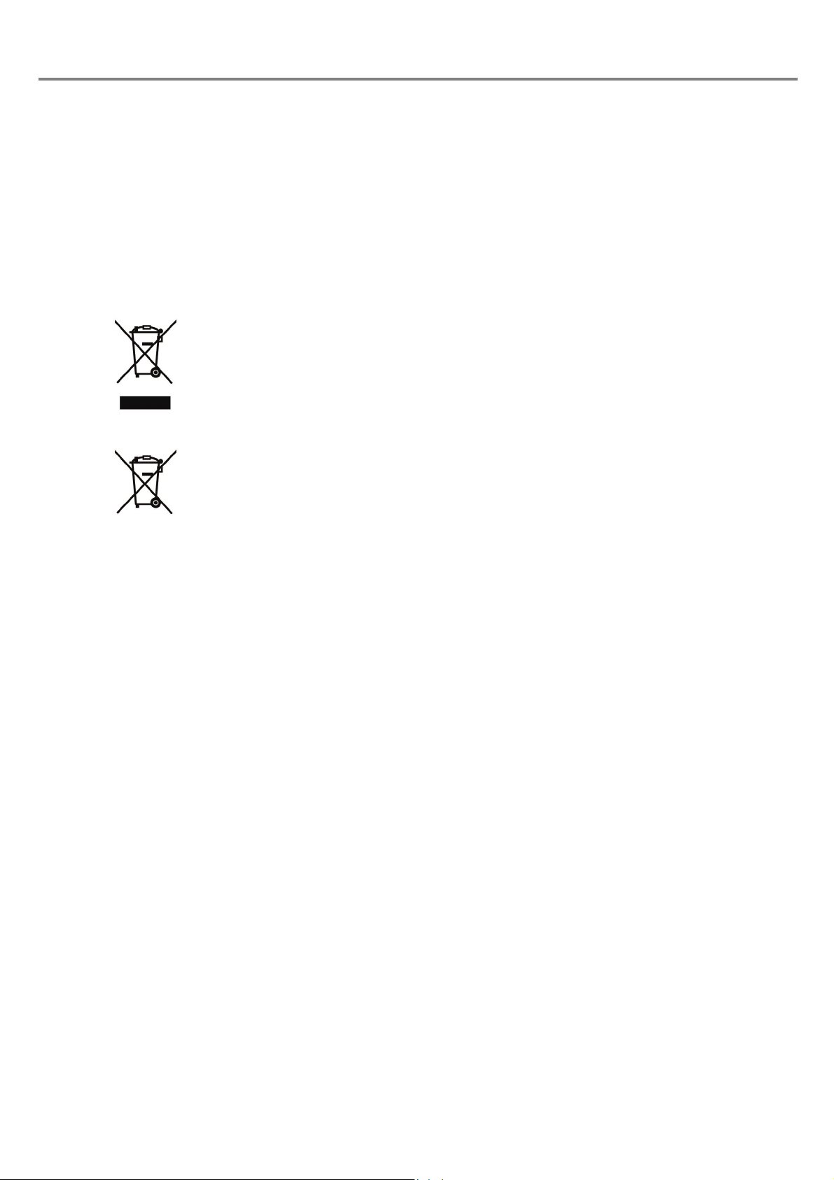
■ Disposal of old equipment and batteries
Only for European Union and countries with recycling systems
These symbols on the products, packaging, and/or accompanying documents mean that used electrical and electronic products and batteries must not be mixed with general household waste.
For proper treatment, recovery and recycling of old products and batteries, please take them to applicable collection points in accordance with your national legislation.
By disposing of them correctly, you will help to save valuable resources and prevent any potential negative effects on human health and the environment.
For more information about collection and recycling, please contact your local municipality.
Penalties may be applicable for incorrect disposal of this waste, in accordance with national legislation.
Note for the battery symbol (bottom symbol)
This symbol might be used in combination with a chemical symbol. In this case it complies with the
requirement set by the Directive for the chemical involved.
Refer to “Detaching Method of Battery” (P.20) for details.
19
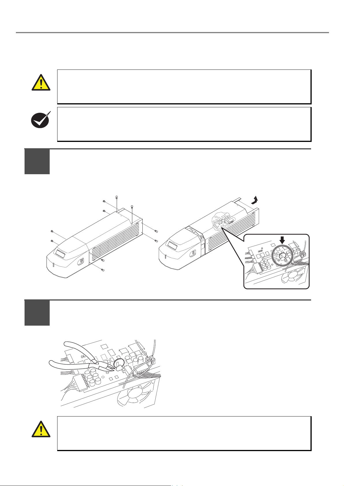
◆ Detaching Method of Battery
CAUTION
CHECK
1
2
CAUTION
The method for detaching the used battery installed in the laser marker to be disposed is described below in
accordance with the EU Battery Directive (2006/66/EC).
• When detaching the used battery, be sure to disconnect the power cable so that the power shall
not be supplied to the device.
• This method is never described with the replacing method of the battery. The battery is replaced
by our service section. Please contact our sales office.
Note that the indication of the life duration of the battery might be 10 years.
Remove the rear cover of the head.
Remove 10 screws of the rear cover as shown in the figure below, and then slide the cover
backward.
After removing the cover, the battery is installed in the position as shown in the figure below
(surrounded with circle).
20
Remove the used battery.
Remove the adhesive used for enhansing the installation of the battery to the board using the
nipper.
Then, cut the terminal of the battery one by one, and remove the battery from the board.
• Be sure to cut the terminal of the battery one by one. Cutting two terminals of the battery at the
same time might cause the electrical shock.

MEMO
21

Contents
Preface.........................................................................................................................2
Cautions in Handling Laser Beam................................................................................6
Safety Protection Measures .........................................................................................8
Functions for Safety Measures ..................................................................................10
Cautions in Handling ..................................................................................................15
Contents.....................................................................................................................22
Construction of Manual ..............................................................................................27
1 Preparation ................................................................................................. 31
1-1 Package Check....................................................................................................32
1-2 Name of Each Part...............................................................................................34
1-2-1 Head.........................................................................................................34
1-2-2 Power Supply BOX...................................................................................35
1-3 Installation............................................................................................................36
1-3-1 Installation Method ...................................................................................36
1-3-2 Center of Marking.....................................................................................38
1-3-3 Useful Function for Installation .................................................................39
1-4 Connecting Laser Marker.....................................................................................40
1-4-1 Connecting Head and Power Supply BOX...............................................40
1-4-2 Connecting Laser Marker and Personal Computer ..................................41
1-5 Connecting with External Device .........................................................................42
1-5-1 Operation Sample Using External Control Device ...................................42
1-5-2 Operation Procedure Using External Control ...........................................43
1-5-3 Shift to Remote Mode...............................................................................44
2 Basic Operation Procedure ........................................................................ 45
2-1 When Using Laser Marker for the First Time .......................................................46
2-1-1 Preparation of Laser Marker Operation....................................................47
2-1-2 Startup of Laser Marker............................................................................48
2-1-3 Procedure from Laser Marker Setting to Test Marking ............................49
2-1-4 Turn OFF Power of Laser Marker ............................................................57
2-2 Setting Procedure for Basic Function ..................................................................58
2-2-1 Mark Counter............................................................................................58
2-2-2 Mark Lot No..............................................................................................62
2-2-3 Mark Expiry Date......................................................................................66
2-2-4 Mark Current Date....................................................................................71
3 Description of Operation Screen ................................................................ 75
3-1 Description of Main Screen..................................................................................76
3-1-1 Main Screen .............................................................................................76
3-1-2 Construction of Main Screen ....................................................................78
3-1-3 Menu Function..........................................................................................79
22

3-1-4 Tool Button Function................................................................................ 81
3-2 File Selection ....................................................................................................... 82
3-2-1 Marking File..............................................................................................82
3-2-2 Registration File ....................................................................................... 83
3-2-3 Registration File and Marking File............................................................ 86
3-3 Character Setting................................................................................................. 88
3-3-1 Character Setting Screen......................................................................... 88
3-3-2 Input of Marking Character....................................................................... 89
3-3-3 Input of Function Character...................................................................... 90
3-4 Function Setting................................................................................................. 104
3-4-1 Function Setting Screen......................................................................... 104
3-4-2 Setting of Expiry Date Function..............................................................105
3-4-3 Setting of Counter Function ................................................................... 106
3-4-4 Setting of Lot Function ........................................................................... 107
3-5 Marking Condition.............................................................................................. 110
3-5-1 Setting Screen of Marking Condition...................................................... 110
3-5-2 General Conditions ................................................................................ 111
3-5-3 Character Condition ...............................................................................115
3-5-4 CAD Condition ....................................................................................... 120
3-5-5 Laser Check...........................................................................................124
3-6 Laser Setting...................................................................................................... 126
3-6-1 Screen for Laser Setting ........................................................................ 126
3-6-2 Line Width .............................................................................................. 127
3-6-3 Marking Pitch ......................................................................................... 127
3-6-4 Adjustment of Laser Start/End Points .................................................... 128
3-6-5 Adjustment of Marking Quality ............................................................... 129
3-7 Image Display .................................................................................................... 130
3-7-1 Image Display Screen............................................................................ 130
3-7-2 Magnification Method .............................................................................131
3-7-3 Adjustment of Marking Position.............................................................. 132
3-7-4 Adjustment of Display Position............................................................... 133
3-8 Guide Indication................................................................................................. 134
3-8-1 Center Position Indication ......................................................................134
3-8-2 Guide Indication ..................................................................................... 134
3-8-3 Cautions................................................................................................. 136
3-9 Test Marking ...................................................................................................... 138
3-9-1 Test Marking .......................................................................................... 138
3-10 Send/Read....................................................................................................... 140
3-10-1 File Transmit ....................................................................................... 140
3-10-2 File List................................................................................................ 142
3-10-3 Backup ................................................................................................ 142
3-10-4 Restore................................................................................................143
3-11 PC Control/Remote Mode................................................................................ 144
23

3-11-1 Remote Mode......................................................................................144
3-11-2 PC Control Mode.................................................................................146
3-12 Switching Language between Japanese and English......................................147
3-13 Error History.....................................................................................................148
3-14 Environmental Setting......................................................................................150
3-14-1 Environmental Setting Related to Laser Marker...................................150
3-14-2 Environmental Setting Related to PC...................................................152
4 External Control........................................................................................ 155
4-1 Control Through I/O Connector..........................................................................156
4-1-1 Before External Controlling Laser Marker Using I/O Connector.............156
4-1-2 I/O Connector .........................................................................................157
4-1-3 Signal Name and Content of I/O Connector...........................................159
4-1-4 Input Rating and Input Circuit.................................................................160
4-1-5 Output Rating and Output Circuit ...........................................................161
4-1-6 Input/Output Operation...........................................................................162
4-1-7 Timing Chart...........................................................................................164
4-2 Control with RS-232C ........................................................................................166
4-2-1 Before External Controlling Laser Marker Using RS-232C ....................166
4-2-2 RS-232C Connector ...............................................................................167
4-2-3 Specification for RS-232C ......................................................................167
4-2-4 Setting of Communication Condition ......................................................168
4-2-5 Connecting Sample of External Control Device .....................................168
4-2-6 Check Connection ..................................................................................169
4-2-7 Sample of Control...................................................................................170
4-2-8 Communication Data Format .................................................................173
4-2-9 Communication Sequence .....................................................................177
4-2-10 Communication Command and Function .............................................180
5 Troubleshooting........................................................................................ 187
5-1 Troubleshooting .................................................................................................188
5-2 Measures for Indicated Error .............................................................................189
6 Maintenance ............................................................................................. 191
6-1 Maintenance ......................................................................................................192
6-1-1 Contamination of f-theta Lens ................................................................192
6-1-2 Air Filter ..................................................................................................192
7 Specification ............................................................................................. 193
7-1 Specification.......................................................................................................194
7-2 Outer Dimensional Drawing ...............................................................................195
7-2-1 Head.......................................................................................................195
24

7-2-2 Power Supply BOX ................................................................................ 196
Appendix ...................................................................................................... 197
Character Code Table.............................................................................................. 198
Readable DXF File................................................................................................... 207
Glossary...................................................................................................................209
Index ............................................................................................................ 212
Index ........................................................................................................................213
25

MEMO
26

Construction of Manual
Before Use
Appendix
Index
Preparation
Chapter
1
Chapter
2
Basic Opreation
Procedure
Chapter
3
Description of
Operation Screen
Chapter
4
Control by
External Device
Chapter
5
Chapter
6
Maintenance
Chapter
7
Specification
Troubleshooting
The important items for safety laser
marker operation are described in
this section.
Be sure to read this section before
using the laser marker.
P. 2
This chapter describes the items
required for using the laser marker.
Be sure to read this chapter at
preparation.
P. 3 1
This chapter describes the basic
operation targetting for the first user
briefly. Since the control sample is
also involved, refer to them
together.
P. 4 5
Read this chapter for operating the
laser marker such as the setting
character to be marked and the
function for marking.
P. 7 5
This chapter describes the connecting
method to the external control devices
(such as PLC, device using external
power supply). Read this chapter
when connecting this product to the
external device.
P. 1 55
This chapter describes the error
messages and measures. Read this
chapter when error message is
appeared or marking is not performed
properly.
P.187
This chapter describes the maintenance,
replacement of filter and cleaning of lens,
etc.
Please read this chapter when performing
maintenance.
P.191
This chapter describes the specification
and outer dimension of laser marker.
P.193
This appendix describes the character
code table.
With this table, the code of character
and symbols to be marked can be
checked.
P.197
With this index, the corresponding
page describing details for desired
contents using the terms.
P.212
27
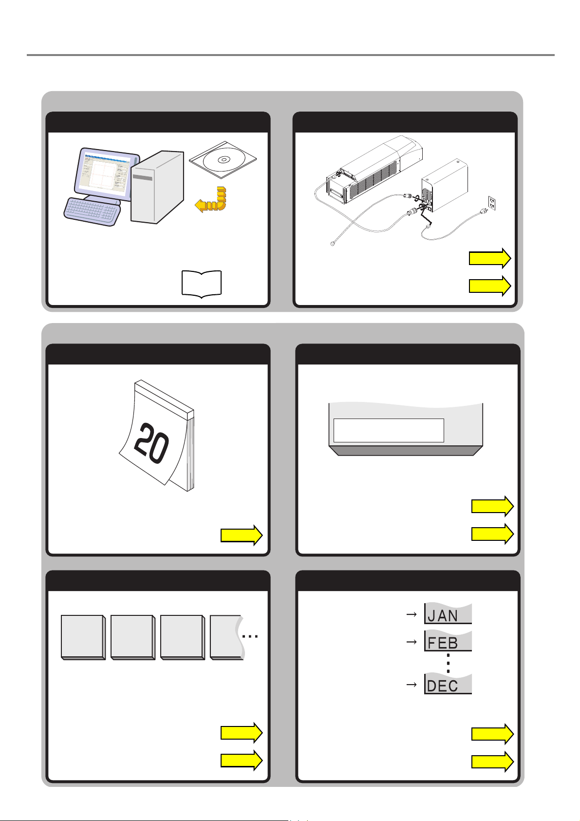
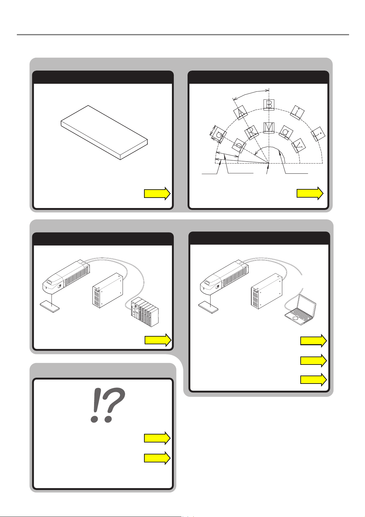
Setup Laser Marker
Install Setting Software Install and Connect
Marking
Mark Date Mark Expiry Date
Mark Counter Mark Lot
“Let’s Try” Contents
2020. 3
.20.
Expiry DateExpiry Date
0001 0002 0003 0004
The user can refer to the corresponding pages in which the contents of what user “tries to do” are described
using this “Let’s Try” Contents.
“Installation” P.36
Installation
Install
Manual
“Connecting Laser Marker” P.40
“Input current date” P.90
“Setting of Expiry Date Function” P.105
January
February
“Input expiry date” P.93
“Setting of Counter Function” P.106
“Input counter” P.96
28
December
“Input lot” P.98
“Setting of Lot Function” P.107
Control by I/O
Control by RS-232C
When in Trouble...
Control Laser Marker From External Device
Marking
Mark Logo Set Character Condition
Center Position (X, Y)
Character
Height
Start
Radius
Line Interval
Radius
Character
Width
Character Interval
Angle
Start Angle
ABCD
ABC
ABC
“CAD Condition” P.120
PLC
“Control Through I/O Connector” P.156
“Communication Command and Function” P.180
“Character Condition” P.115
Personal
Computer
“Control with RS-232C” P.166
“Troubleshooting” P.188
“Measures for Indicated Error” P.189
“Details of Commands” P.180
29

MEMO
30
 Loading...