

Page 1
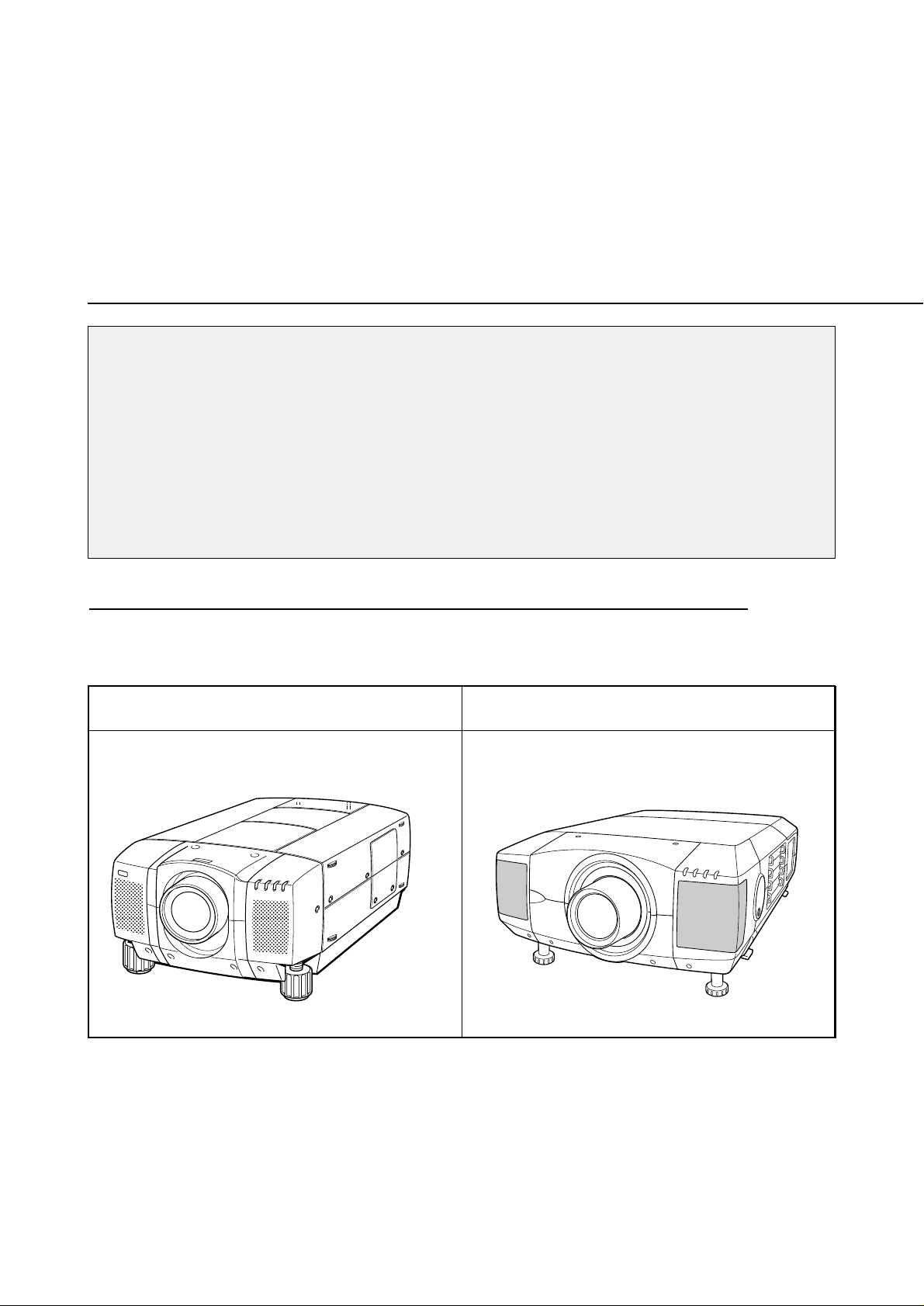
Type of the Cabinet (1) See Page 2
LCD PROJECTOR LENS
MODEL NO. LNS-W03
LENS REPLACEMENT
AND INSTALLATION PROCEDURES
NOTES ON REPLACEMENT AND INSTALLATION
The procedures and the needed pars for lens installation depend on the type of
cabinet. Before installing or replacing the lens, make sure the type of cabinet and be
sure to refer to the Installations corresponding with your projector.
When installing or replacing the lens, make sure the Lens Model No. matches with
your projector. Refer to the catalog, or contact your sales dealer for the proper Lens
Model No.
TYPE OF THE CABINET AND INSTALLATION PROCEDURES
Refer to the Installation procedure corresponding to your projector and install the lens
correctly. (See the chart below.)
Type of the Cabinet (2) See Page 4
1AA6P1P2952-- (ICYZ)
※ For use the other models (other than above cabinet), contact your sales dealer.
Page 2
Some parts are not used for installation or replacement. Keep these parts for later use.
Note : Figures in this manual may be differ from the actual product.
NOTES ON LENS INSTALLATION
The ZOOM, FOCUS and LENS SHIFT adjustment on the Top Control or the
Remote Control cannot be operated with this Lens.
• Lens installation and replacement should be made by the qualified service personnel.
• Be sure to install the lens following this procedure precisely.
• The lens cover is on the lens for protection. Be sure to replace the lens cover
before installation.
• When installing or replacing the lens, be careful not to stain, scratch or damage
the lens.
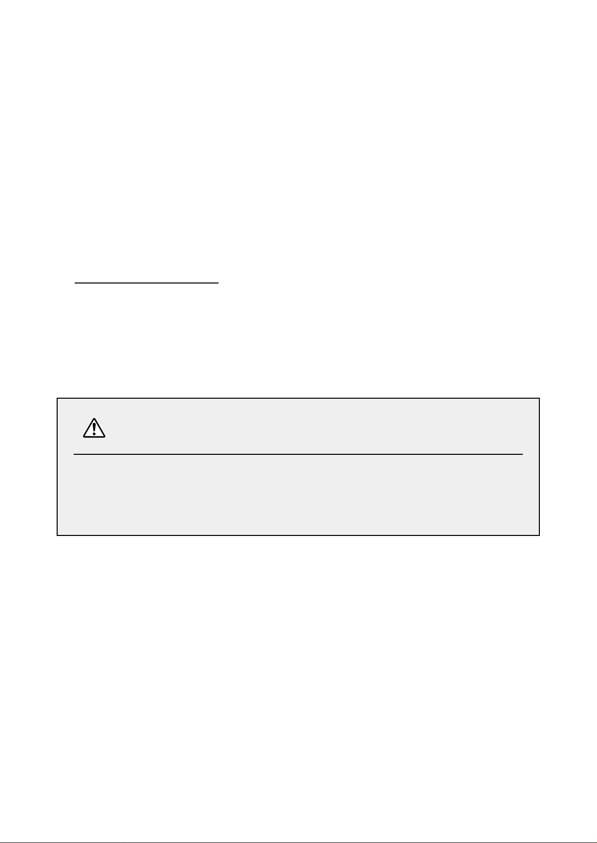
After installing or replacing the lens, be sure to check the following for safety.
1. Check the lens is securely fixed by 4 screws.
2. Check no part is missing, or no mounting part is loose.
BE SURE T O CHECK FOR SAFETY
LIST OF CONTENTS
Following parts are included in the packing.
• LENS 1 pc.
• DRIVER 1 pc.
• LIGHT-BLOCK SHEET 2 pcs.
-1-
Type FE1 (Part No. 610 280 2634) For use the Type (1) Cabinet
Type FB1 (Part No. 610 285 8211) For use the Type (2) Cabinet
Page 3
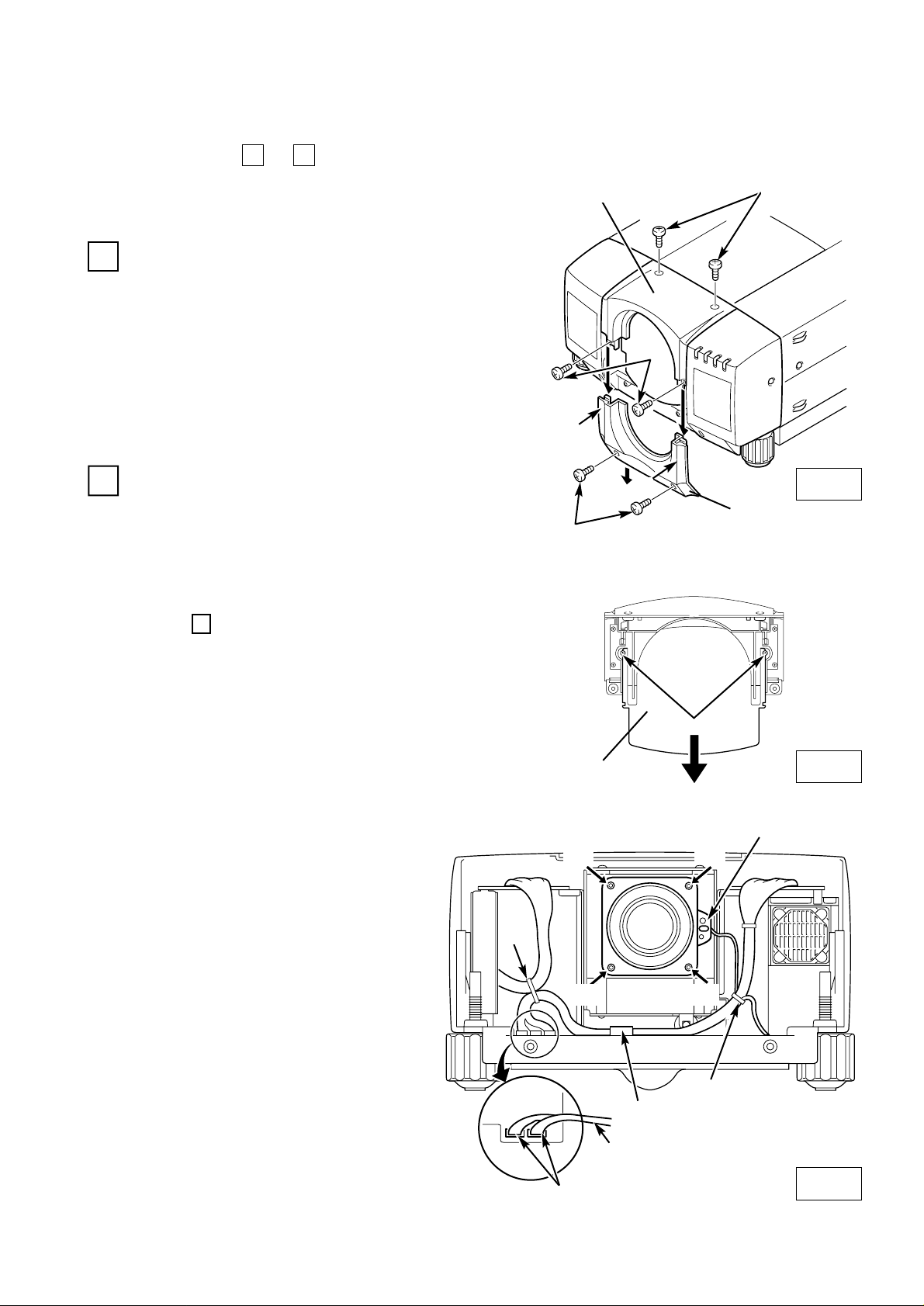
LENS REPLACEMENT AND INSTALLATION PROCEDURE
1. Remove screws A (2 screws).
2. Pull down the lower lens cover while pushing
the part D, then remove it.
3. Remove screws B (2 screws).
4. Remove screws C (2 screws) and remove
upper lens cover.
1
A
Fig-1
Fig-2
● IN CASE OF MODEL WITHOUT LENS
Remove 2 screws and pull down the plate.
2
UPPER LENS COVER
LOWER LENS COVER
C
B
D
D
COVER PLATE
REMOVE THE LENS COVER. (See figure-1)
(At the step , insert the light-block sheet in
the same position as the removed cover plate
has been placed. Two screws are not used.)
4
REMOVE THE COVER PLATE OF THE LENS COVER. (See figure-2)
LENS
MOTOR LEAD
CONNECTORS " K16A" and " K16B"
(D)
(D)
(D)
(D)
B
A
LENS MOTOR
Fig-3
❋Figure shown inside of the cabinet.
REMOVE THE LENS. (See figure-3.)
1. Disconnect the Lens Shift connector
“K16A” from circuit board.
2. Disconnect the Zoom and Focus connector “K16B” from circuit board.
3. Loosen the A, B wire holder and
remove the lens motor lead.
4. Remove screws D (4 screws) which
fastens the lens and remove the lens.
● IN CASE OF MODEL WITH LENS
A
Perform the steps to for lens replacement and installation.
51
SCREWS
First set the lens at the center position with lens
shift adjustment.
(Type 1 Cabinet)
Disconnect the Lens Shift connector
("K16A") from circuit board. (See Fig. 3.)
-2-
Page 4
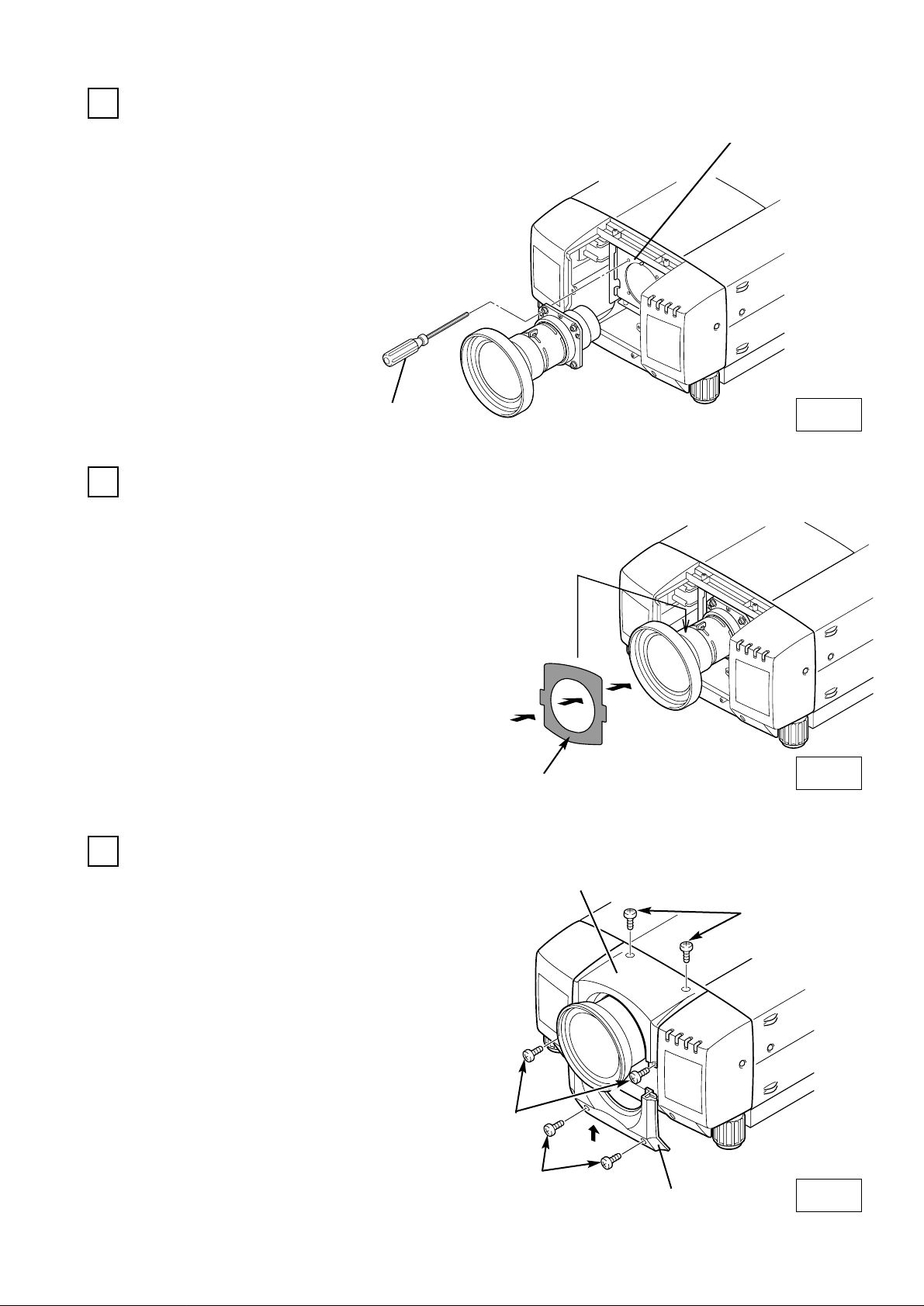
MOUNT THE LENS COVER. (See figure-6)
INSTALL THE LENS. (See figure-4)
1. Remove protective caps(front and
back) on the lens.
2. Mount the lens on mounting bracket
of the main cabinet with 4 screws.
Use the screws included with the lens.
Use the driver included with the lens to
fasten the screws.
(After using, keep it for latter use.)
3
A
INSTALL THE LIGHT-BLOCK SHEET. (See figure-5)
4
Install the light-block sheet around the lens
as shown in the illustration. Use the sheet
included with the lens.
Make sure the part no. and mark (TOP and
BACK) on Light-Block Sheet and set them
properly.
1. Insert the upper part lens cover and fix
them with screws A (4 screws).
2. Insert the lower part lens cover and fix
them with screws B. (2 screws).
5
LENS MOUNTING BRACKET
ATTACHED DRIVER
UPPER LENS COVER
LOWER LENS COVER
A
B
Fig-4
Fig-5
Fig-6
When in install the both upper and lower
lens covers, install the light-block sheet so
that it should be placed in the guide slot.
(place of the cover plate had been placed.
See figure-2.) If the installation of light-block
sheet is incorrect, it will be the cause of
leakage of light or the dust entering at the
main cabinet.
LIGHT-BLOCK SHEET
Type FE1
(Part No. 610 280 2634)
-3-
ADJUST FOCUS
Adjust focus following Focus Adjustment on
page 6.
Page 5
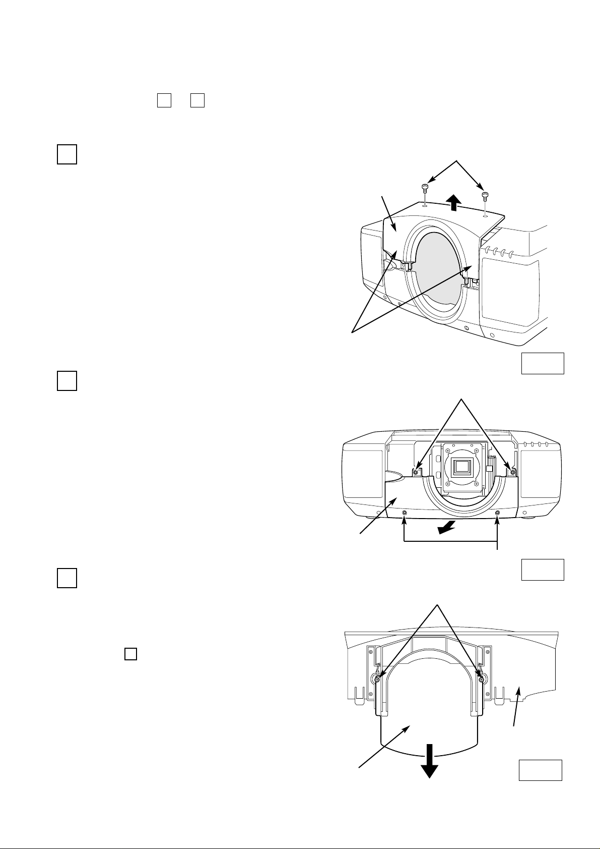
1. Remove screws A (2 screws).
2. Push part B and pull Upper Lens Cover up.
1
Fig-1
Fig-2
2
REMOVE THE UPPER LENS COVER. (See figure-1)
(At the step , insert the light-block sheet in
the same position as the removed cover plate
has been placed. Two screws are not used.)
6
Perform the steps to for lens replacement and installation.
71
First set the lens at the center position with lens shift adjustment.
UPPER LENS
COVER
A
LOWER LENS
COVER
C
COVER PLATE
UPPER LENS
COVER
D
C
B
Fig-3
1. Remove screws C (4 screws).
2. Pull Lower Lens Cover toward front and
remove.
REMOVE THE LOWER LENS COVER. (See figure-2)
3
1. Remove screws D (2 screws) and Cover
Plate on the back of Upper Lens Cover.
REMOVE THE COVER PLATE. (See figure-3)
LENS REPLACEMENT AND INSTALLATION PROCEDURE
(Type 2 Cabinet)
-4-
Page 6

INSTALL THE LENS. (See figure-5)
1. Remove protective caps(front and
back) on the lens.
2. Mount the lens on mounting bracket
of the main cabinet with 4 screws.
Use the screws included with the lens.
Use the driver included with the lens to
fasten the screws.
(After using, keep it for latter use.)
5
INSTALL THE LIGHT-BLOCK SHEET. (See figure-6)
6
Install the light-block sheet around the lens
as shown in the illustration. Use the sheet
included with the lens.
Make sure the part no. and mark (TOP and
BACK) on Light-Block Sheet and set them
properly.
LENS MOUNTING BRACKET
ATTACHED DRIVER
Fig-5
Fig-6
LIGHT-BLOCK SHEET
Type FB1
(Part No. 610 285 8211)
LEAD
HOLDER
CONNECTOR
"K96S"
Fig-4
DISCONNECT THE LENS SHIFT CONNECTORS. (See figure-4)
Disconnect the Lens Shift Connectors
("K96S" and "K96R") from circuit board.
4
CONNECTOR
"K96R"
-5-
ADJUST FOCUS
Adjust focus following Focus Adjustment on
page 6.
Page 7

FOCUS ADJUSTMENT
Set up the projector and project image on the screen.
1. Loosen the Focus Lock Screw on the projection
lens.
2. Rotate the projection lens to obtain proper focus
on center area of the screen.
When the distance of the screen and lens is 1 meter,
set
● mark (yellow) of the lens on Focus Lock Screw
position.
3. Lock the Focus Lock Screw securely.
When proper focus is not observed at outer area of
the screen, proceed following adjustments.
4. Loosen the Focus Lock Ring on the projection
lens. (Turn the Lock Ring to counter-clockwise.)
5. Rotate the lens to obtain proper focus on outer
area of the screen.
6. Lock the Focus Lock Ring securely. (Turn the Lock
Ring to clockwise.)
If proper focus is not observed entire screen, repeat
above adjustment 1~ 6.
Focus Lock Screw
Focus Lock Ring
LOWER LENS
COVER
UPPER LENS
COVER
LIGHT-BLOCK
SHEET
FLAP
Slide into front
of the flap.
Slide into front
of the flap.
FLAP
Slide upper both side of LIGHT BLOCK
Sheet into between and
.
CABINET
GUIDE
MOUNT THE LENS COVER. (See figure-7)
7
1. Replace Lower Lens Cover. Slide Light-Block Sheet into the guide of Lower Lens Cover
and set them in front of the flap. (See Fig. 7.) Fix Lower Lens Cover with 4 Screws C.
(See Fig. 2.)
2. Replace Upper Lens Cover. Slide Light-Block Sheet into the guide of Upper Lens Cover
and set them in front of the flap. (See Fig. 7.) Fix Upper Lens Cover with 2 Screws A.
(See Fig. 1.)
Fig-7
● mark (yellow)
-6-
1
2
1
2
Page 8

キャビネットの形状 (2)4ページ参照
1AA6P1P2952-- (ICYZ)
液晶プロジェクターレンズ
品番 LNS-W03
レンズ交換・取付作業手順書
ご注意:レンズを取り付けるまえに
レンズはご使用になるプロジェクターのキャビネットの形状により、取付部品、お
よび取付方法が異なります。取り付けるまえにキャビネットの形状をよくお確かめ
のうえ、キャビネットに合った取付作業手順にしたがい、正しくご使用ください。
レンズは液晶プロジェクターに適合した正しい品番のものをお使いください。詳し
くはカタログ、または販売店でお確かめください。
キャビネットの形状と取付作業手順
キャビネットの形状により取付作業手順が異なります。下図を参照のうえ、正しい作業
手順で行ってください。
キャビネットの形状 (1)2ページ参照
※上記形状以外の機種へのご使用については取扱販売店へご相談ください。
Page 9

レンズの取り付け、または交換のあとに、お使いにならない部品が残る場合があります。
これらの部品は後日必要となる場合がありますので、大切に保管してください。
※説明文中の図は実際のものと異なる場合があります。
取り付け作業上の注意
このレンズは、リモコンまたは液晶プロジェクター本体でのズーム、フォーカス
およびレンズシフト調整はできません。
●レンズの取り付け、交換作業はサービス技術員が行ってください。
●レンズの取り付け、交換作業はこの作業手順書にしたがい、正しく行ってくだ
さい。
●レンズにはレンズ保護のためのキャップが付いています。レンズを取り付ける
まえに、かならずキャップをはずしてください。
●レンズの取り付け、取り外しのとき、レンズの表面を手でさわったり傷を付け
たりしないようご注意ください。
レンズを取り付けたあと、レンズカバーを取り付けるまえに、つぎの点検を行って
ください。
1. レンズが4本のスクリューでしっかり固定されているか。
2. 外れている部品はないか。
安全のため、必ずつぎの点検と確認を行ってください。
部品明細
梱包には以下の部品が入っています。
・レンズ本体 1個
・専用ドライバー 1本
・遮光プレート 2枚
型番 FE1(品番 6102802634)キャビネット形状 (1)へ使用
型番 FB1(品番 6102858211)キャビネット形状 (2)へ使用
-1-
Page 10

1. スクリューA(2本)を外します。
2. レンズカバー下のD部を押さえ下方向に引いて外します。
3. スクリューB(2本)を外します。
4. スクリューC(2本)を外し、レンズカバーの上を外します。
レンズの交換と取り付けかた (キャビネット形状 1の場合)
レンズカバーを外す。(図1参照)
1
2本のスクリューを外し、プレートを下方向に引くと外れます。
(手順 で遮光プレートを取り付けるとき、外したカバ
ープレートと同じ位置に差し込んでください。2本のスク
リューは不要です。)
4
2
カバープレート
●レンズなしモデルの場合
レンズカバーのカバープレートを外します。(図2参照)
図2
●レンズ付モデルの場合
レンズモーター
レンズモーターリード
K16A,K16Bコネクター
図3
B
(D)
(D)
(D)
(D)
✽図はキャビネット内部の様子を
示しています。
レンズを外します。(図3参照)
1.基板のレンズシフトコネクターK16Aを
外します。
2. 基板のズーム、フォーカスコネクター
K16Bを外します。
2. ワイヤーホルダーA,Bをゆるめ、レンズモ
ーターのリードを外します。
3.レンズを固定しているスクリューD(4本)
を外し、レンズを外します。
A
レンズカバー上
C
D
B
A
レンズカバー下
図1
D
レンズの交換・取り付けは 〜 の手順で行います。
51
スクリュー
基板のレンズシフトコネクターK16Aを外します。
(図3参照)
はじめにレンズシフトでレンズを移動範囲の中央にします。
-2-
Page 11

付属ドライバー
レンズマウントブラケット
図4
レンズを取り付けます。(図4参照)
3
1. はじめにレンズに取り付けられている保護用のキャップ
を外します。(前後2ケ所)
2. レンズに付属のスクリュー4本で、レンズを液晶プロジ
ェクターのレンズマウントブラケットへ取り付けます。
スクリューの締め付けは付属のドライバーをご使用くだ
さい。(ドライバーはご使用になったあと、大切に保管し
てください。あとでレンズの取り付け取り外しのとき必
要です。)
遮光プレートを取り付けます。(図5参照)
4
レンズカバーを取り付けます。(図6参照)
5
1. レンズカバー上を、上から差し込み、スクリューA
(4本)で固定します。
2. レンズカバー下を、下から差し込み、スクリューB
(2本)で固定します。
A
A
B
レンズカバー上
レンズカバー下
図6
図5
上下のレンズカバーを取り付けるとき、遮光プレート
を上下レンズカバーのガイドスロットの中(カバープ
レートが入っていた所。図2参照)に入る様に取り付
けてください。遮光プレートが正しく取り付けられて
いないと、光モレを起こしたり、本体にホコリが入る
原因となります。
遮光プレート
型番 FE1
(品番 6102802634)
レンズの図の位置に遮光プレートを取り付けます。
(レンズに付属されている正しい型番のものをご使用
ください。)
遮光プレートには取り付け方向が表示されています。
THISSIDEBACKを後方に、TOPを上側に取り付け
ます。
-3-
フォーカスを合わせます。
ここで映像を投映し、フォーカスを合わせます。
{フォーカス調整のしかた (ページ 6)参照 }
Page 12

レンズカバー上
A
レンズカバー下
C
カバ−プレ−ト
レンズカバー上
D
C
B
1. スクリューA(2本)を外します。
2. B部を矢印の方向に押し、レンズカバー上を上方へ引い
て外します。
レンズの交換と取り付けかた (キャビネット形状 2の場合)
レンズカバー上を外す。(図1参照)
1
(手順 で遮光プレートを取り付けるとき、外したカ
バープレートと同じ位置に差し込んでください。2本の
スクリューは不要です。)
6
2
図2
図3
図1
レンズの交換・取り付けは 〜 の手順で行います。
71
はじめにレンズシフトでレンズを移動範囲の中央にします。
1. スクリューC(4本)を外します。
2. レンズカバー下を手前に引いて外します。
3
1. レンズカバー上裏面のスクリューD(2本)を外します。
2. カバープレートを下方へ引いて外します。
レンズカバー下を外す。(図2参照)
レンズカバーのカバープレートを外します。(図3参照)
-4-
Page 13

図4
レンズを取り付けます。(図5参照)
1. はじめにレンズに取り付けられている保護
用のキャップを外します。(前後2ケ所)
2. レンズに付属のスクリュー4本で、レンズ
を液晶プロジェクターのレンズマウントブ
ラケットへ取り付けます。スクリューの締
め付けは付属のドライバーをご使用くださ
い。(ドライバーはご使用になったあと、大
切に保管してください。あとでレンズの取
り付け取り外しのとき必要です。)
遮光プレートを取り付けます。(図6参照)
5
6
4
図5
図6
遮光プレート
型番 FB1
(品番 6102858211)
レンズマウントブラケット
付属ドライバー
K96Sコネクター
レンズシフトコネクターを取り外します。(図4参照)
K96Rコネクター
リードホルダー
基板のレンズシフトコネクターK96Sおよび
K96Rを外します。(図3参照)
レンズの図の位置に遮光プレートを取り付けます。
(レンズに付属されている正しい型番のものをご使用
ください。)
遮光プレートには取り付け方向が表示されています。
THISSIDEBACKを後方に、TOPを上側に取り付け
ます。
-5-
フォーカスを合わせます。
ここで映像を投映し、フォーカスを合わせます。
{フォーカス調整のしかた (ページ 6)参照 }
Page 14

レンズカバー下
レンズカバー上
遮光プレート
フラップ
フラップの前面へ
差し込む
フラップの前面へ
差し込む
フラップ
遮光プレート上部の両サイドを と の
間に差し込みます。
キャビネット上
ガイド
図7
フォーカス固定リング
レンズを取り付けます。(図7参照)
7
フォーカス固定スクリュー
フォーカス調整のしかた。
1. レンズカバー下を取り付けます。遮光プレートをカバー下に差し込んで取り付けます。
遮光プレートがカバー下のフラップ前面になる様に取り付けてください。(図7-参照)レンズカバー下の
スクリューの取り付けは図-2を参照ください。
2. レンズカバー上を取り付けます。遮光プレートをカバーのガイドとキャビネットの間に差し込みます。
遮光プレートはフラップの前面になる様に取り付けます。(図-7参照)上面カバーを2本のスクリューで
取り付けます。スクリューの取り付けは、図-1を参照ください。
プロジェクターを設置場所に据え付け、電源を入れ、
映像を投映します。プロジェクターの位置を調整し、
投映位置を合わせます。
1.フォ−カス 固定スクリューを緩めます。
2.レンズを回転させ画面中央のフォ−カスを合わせま
す。{プロジェクターとスクリ−ンの距離が1mの場
合はフォ−カス固定スクリューの位置をレンズの●
(黄色の丸印)に合わせる}。
3.フォ−カス 固定スクリューを締めます。
もし画面周辺のフォーカスが合っていない場合は以下
の調整を行います。
4.フォ−カス固定リングを左に回し緩めます。
5.レンズを回転させスクリ−ン周辺のフォーカスを合
わせます。
6.フォ−カス固定リングを右に回し締めます。
全体のフォ−カスが合っていない場合、1〜6をくり返
しフォーカスを合わせます。
黄色の丸印
-6-
2
1
1
2
 Loading...