

Page 1
This product complies with the RoHS Directive (EU 2002/95/EC).
0
0
10
20
30
40
50
20 40 60 80 100
02.0 3.0 4.0 5.0 6.0 −20 20 40
60
80 100
10
1
3
5
10
10
50
100
500
1 000
30
50
100
30
50
100
300
500
1 3 5 10 30 50 100
−90
0
20
40
100
120
y
80
60
−60 −30 300 60 90−90
0
20
40
100
120
x
80
60
−60 −30 300 60 90
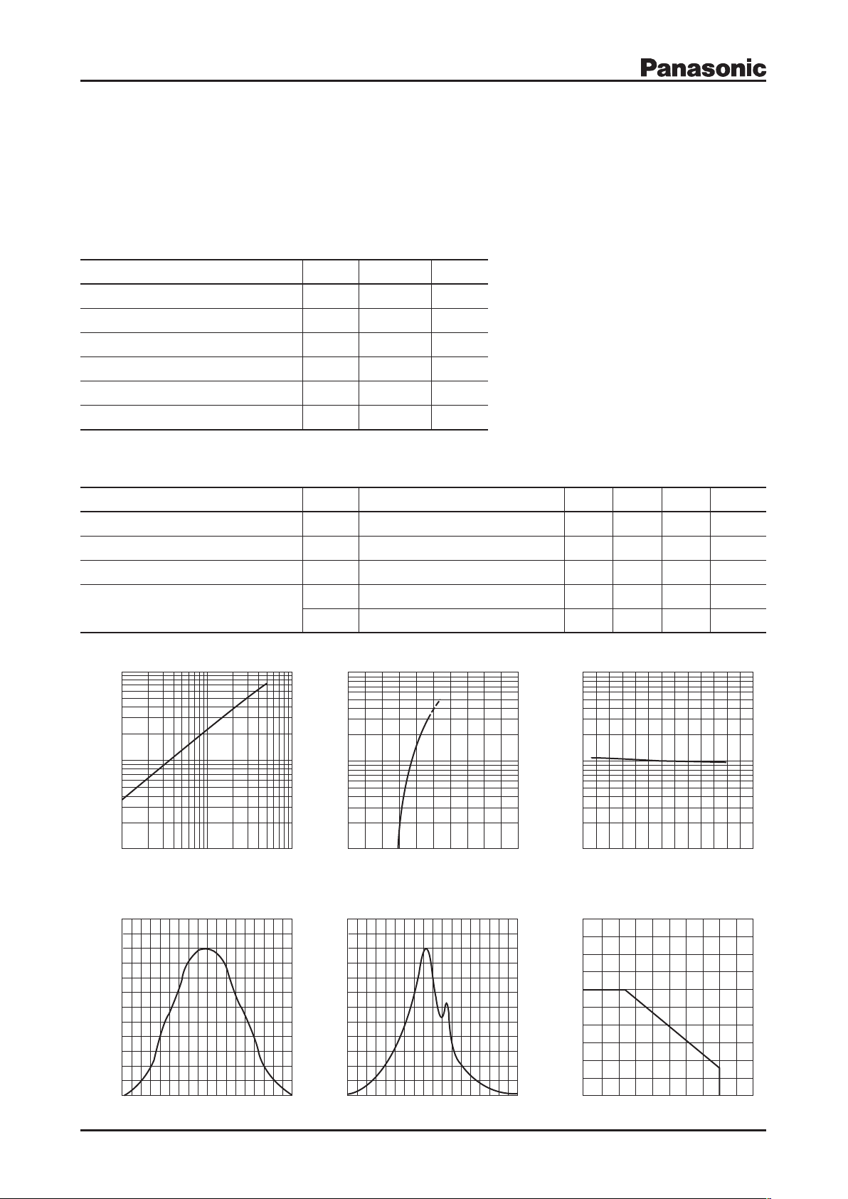
Angle ( ° )
Relative luminous intensity (%)
Relative luminous intensity (%)
Directive characteristics Directive characteristics
Angle ( ° )
IO I
F
IF V
F
IF T
a
Ambient temperature Ta (°C)
Ambient temperature Ta (°C)
Forward current I
F
(mA)
Forward voltage VF (V)Forward current IF (mA)
Luminous intensity I
O
(mcd)
Relative luminous intensity T
a
Relative luminous intensity (%)
Forward current I
F
(mA)
Light Emitting Diodes
LNG0A8CYBZ
Oval Type
φ4.0 mm
Absolute Maximum Ratings Ta = 25°C
Parameter Symbol Rating Unit
Power dissipation P
Forward current I
Pulse forward current
*
Reverse direct current I
Operating ambient temperature T
Storage temperature T
Note) *: The condition of IFP is duty 10%, Pulse width 1 msec.
I
FP
RDC
opr
stg
D
F
Electro-Optical Characteristics Ta = 25°C±3°C
Parameter Symbol Conditions Min Typ Max Unit
Luminous intensity I
Forward voltage V
Reverse voltage V
Chromaticity coordinates
O
F
RIR
x IF = 20 mA 0.22 0.26
y IF = 20 mA 0.17 0.36
Lighting Color
White
120 mW
30 mA
100 mA
100 mA
–25 to +80
–30 to +100
IF = 20 mA 150 400 mcd
IF = 20 mA 3.7 4.3 V
= 10 mA 2.5 V
°C
°C
Publication date: December 2008
SHD00607BEK
1
Page 2
This product complies with the RoHS Directive (EU 2002/95/EC).
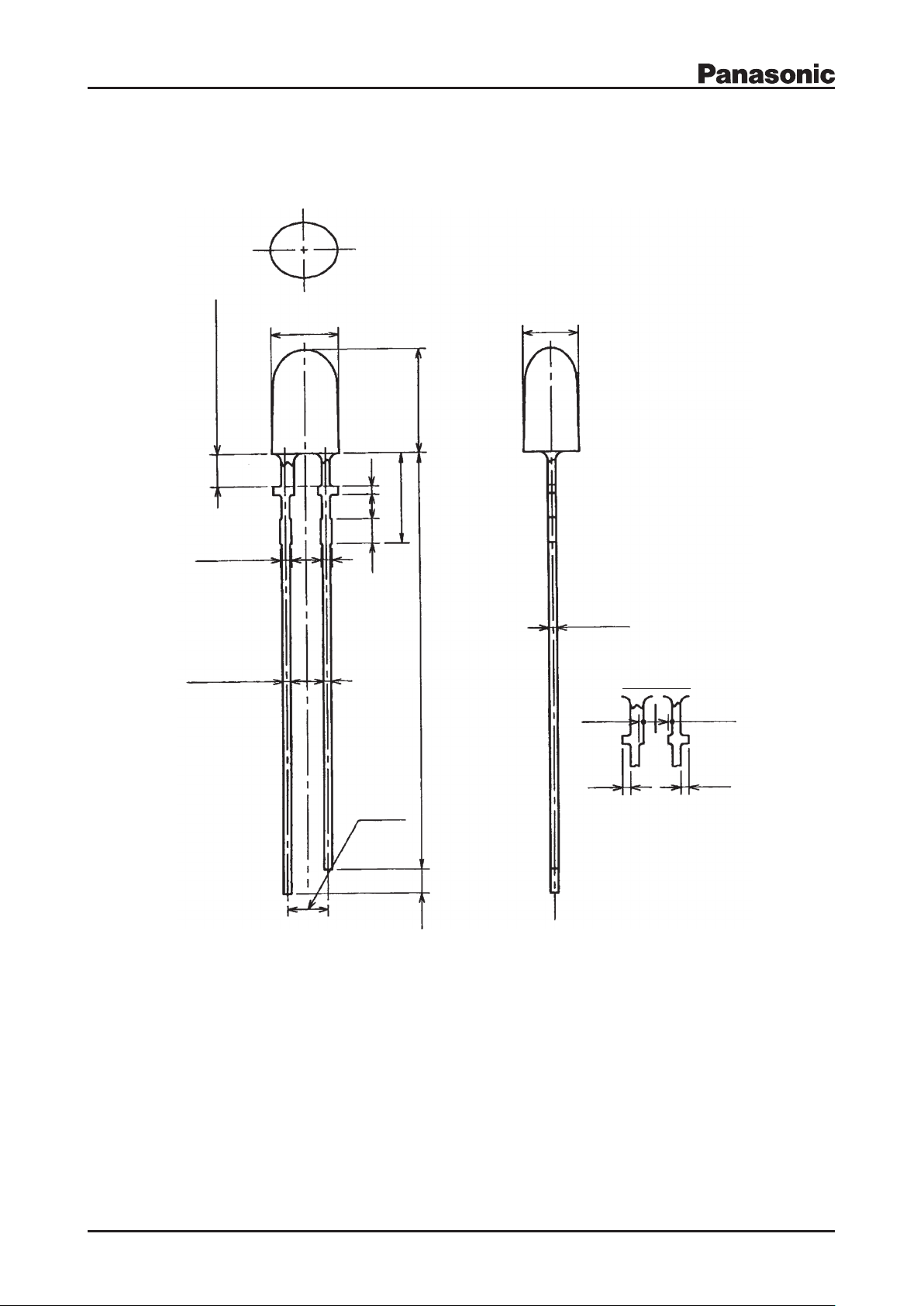
4.2±0.2
0.6±0.1
※
(2.54)
2-0.8 Max
2-0.6±0.1
1.5
5.52
±
0.3
6.4
±
0.2
(1.5)
Not Soldered
2 Max.
無はんだ・樹脂盛上がり部
1.5
0.5
26.0
±
1.0
1 2
(0.3)
(0.3)
(0.5)
(0.5)
3.4±0.2
ストッパ-部
Stopper portion
LNG0A8CYBZ
Package (Unit: mm)
LLXLTN2SYA81
Pin name
1: Anode
2: Cathode
2
SHD00607BEK
Page 3

Request for your special attention and precautions in using the technical information and
semiconductors described in this book
(1)If any of the products or technical information described in this book is to be exported or provided to non-residents, the laws and
regulations of the exporting country, especially, those with regard to security export control, must be observed.
(2)The technical information described in this book is intended only to show the main characteristics and application circuit examples
of the products. No license is granted in and to any intellectual property right or other right owned by Panasonic Corporation or any
other company. Therefore, no responsibility is assumed by our company as to the infringement upon any such right owned by any
other company which may arise as a result of the use of technical information described in this book.
(3)The products described in this book are intended to be used for standard applications or general electronic equipment (such as office
equipment, communications equipment, measuring instruments and household appliances).
Consult our sales staff in advance for information on the following applications:
– Special applications (such as for airplanes, aerospace, automobiles, traffic control equipment, combustion equipment, life support
systems and safety devices) in which exceptional quality and reliability are required, or if the failure or malfunction of the products may directly jeopardize life or harm the human body.
– Any applications other than the standard applications intended.
(4)The products and product specifications described in this book are subject to change without notice for modification and/or im-
provement. At the final stage of your design, purchasing, or use of the products, therefore, ask for the most up-to-date Product
Standards in advance to make sure that the latest specifications satisfy your requirements.
(5)When designing your equipment, comply with the range of absolute maximum rating and the guaranteed operating conditions
(operating power supply voltage and operating environment etc.). Especially, please be careful not to exceed the range of absolute
maximum rating on the transient state, such as power-on, power-off and mode-switching. Otherwise, we will not be liable for any
defect which may arise later in your equipment.
Even when the products are used within the guaranteed values, take into the consideration of incidence of break down and failure
mode, possible to occur to semiconductor products. Measures on the systems such as redundant design, arresting the spread of fire
or preventing glitch are recommended in order to prevent physical injury, fire, social damages, for example, by using the products.
(6)Comply with the instructions for use in order to prevent breakdown and characteristics change due to external factors (ESD, EOS,
thermal stress and mechanical stress) at the time of handling, mounting or at customer's process. When using products for which
damp-proof packing is required, satisfy the conditions, such as shelf life and the elapsed time since first opening the packages.
(7)This book may be not reprinted or reproduced whether wholly or partially, without the prior written permission of our company.
20080805
 Loading...