

Panasonic LN65 Datasheet

Infrared Light Emitting Diodes
LN65
GaAs Infrared Light Emitting Diode
For optical control systems
ø3.5±0.2
4.5±0.3
Unit : mm
4.2±0.3
2.3 1.9
Features
High-power output, high-efficiency : PO = 5.5 mW (typ.)
Good radiant power output linearity with respect to input current
Suited for use in high-speed modulation
Infrared light emission close to monochromatic light :
λP = 950 nm (typ.)
Absolute Maximum Ratings (Ta = 25˚C)
Parameter Symbol Ratings Unit
Power dissipation P
Forward current (DC) I
Pulse forward current I
Reverse voltage (DC) V
Operating ambient temperature
Storage temperature T
*
f = 100 Hz, Duty cycle = 0.1 %
D
F
*
FP
R
T
opr
stg
160 mW
100 mA
1.5 A
3V
–25 to +85 ˚C
– 40 to +100 ˚C
2.8
12.5 min.
10.0 min.
4.8±0.3
1.8
R1.75
2.4 2.4
1.0
2.54
12
Not soldered
2-0.98±0.2
2-0.45±0.15
0.45±0.15
1.2
1: Cathode
2: Anode
Electro-Optical Characteristics (Ta = 25˚C)
Parameter Symbol Conditions min typ max Unit
Radiant power P
Peak emission wavelength λ
Spectral half band width ∆λ IF = 100mA 50 nm
Forward voltage (DC) V
Reverse current (DC) I
Capacitance between pins
C
Half-power angle θ The angle in which radiant intencity is 50% 35 deg.
IF = 100mA 4.3 5.5 mW
O
IF = 100mA 950 nm
P
IF = 100mA 1.3 1.6 V
F
VR = 3V 10 µA
R
VR = 0V, f = 1MHz 50 pF
t
1
LN65 Infrared Light Emitting Diodes
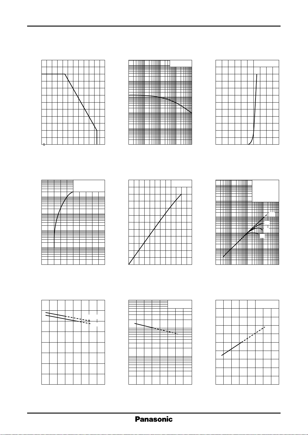
I
— Ta
120
100
(mA)
F
80
60
40
20
Allowable forward current I
0
– 25
F
0 20406080100
Ambient temperature Ta (˚C )
I
— V
4
10
3
10
(mA)
FP
2
10
10
1
Pulse forward current I
FP
tw = 10µs
Duty Cycle = 0.1%
Ta = 25˚C
I
— Duty cycle
FP
2
10
10
(A)
FP
1
–1
10
–2
Pulse forward current I
10
–3
10
10
–1
–2
10
Ta = 25˚C
10 10
1
(mA)
F
Forward current I
2
120
100
80
60
40
20
0
0 0.4 0.8 1.2 2.01.6
Duty cycle (%)
∆P
— I
O
F
120
100
O
80
60
40
Relative radiant power ∆P
20
F
Ta = 25˚C
3
10
O
2
10
10
1
Relative radiant power ∆P
–1
10
I
— V
F
F
Ta = 25˚C
Forward voltage VF (V)
∆P
— I
O
FP
tw = 10µs
(1) f = 100Hz
(2) f = 21kHz
(3) f = 42kHz
(4) f = 60kHz
Ta = 25˚C
(3)
(4)
(1)
(2)
–1
10
0
13524
Forward voltage VF (V)
V
— Ta
1.6
1.2
(V)
F
0.8
Forward voltage V
0.4
0
– 40 0 40 80 120
F
Ambient temperature Ta (˚C )
2
IF = 100mA
50mA
0
20 40 60 80 100 120
0
Forward current IF (mA)
∆P
— Ta
3
10
O
2
10
10
O
IF = 100mA
Relative radiant power ∆P
1
– 40 0 40 80 120
Ambient temperature Ta (˚C )
–2
10
110
2
10
10
Pulse forward current IFP (mA)
λ
— Ta
1000
980
(nm)
P
960
940
920
P
IF = 100mA
Peak emission wavelength λ
900
– 40 0 40 80 120
Ambient temperature Ta (˚C )
3
4
10
 Loading...