

Panasonic LN51L, LN51F Datasheet
Infrared Light Emitting Diodes
LN51F, LN51L
GaAs Infrared Light Emitting Diodes
For optical control systems
Features
High-power output, high-efficiency : PO = 6 mW (typ.)
Fast response : tr, tf = 1 µs (typ.)
Infrared light emission close to monochromatic light :
λ
=950 nm (typ.)
P
Narrow directivity, suitable for effective use of optical output :
θ = 8 deg. (LN51L)
Wide directivity, matched for external optical systems :
θ = 32 deg. (LN51F)
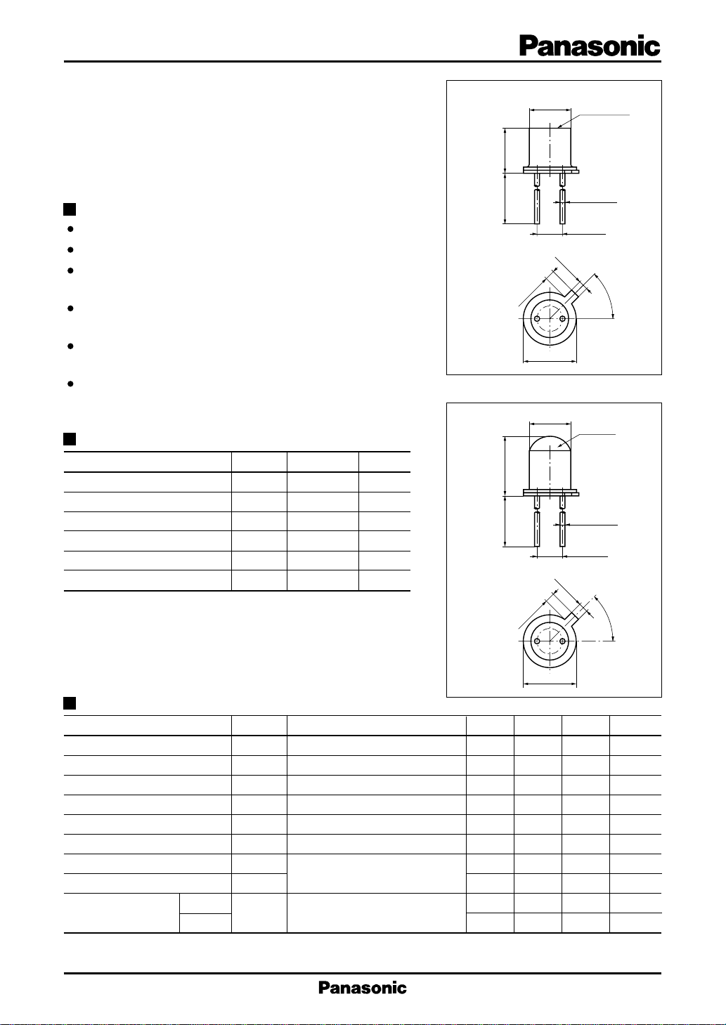
TO-18 standard type package
Absolute Maximum Ratings (Ta = 25˚C)
Parameter Symbol Ratings Unit
Power dissipation P
Forward current (DC) I
Pulse forward current I
Reverse voltage (DC) V
Operating ambient temperature
Storage temperature T
*
f = 100 Hz, Duty cycle = 0.1 %
D
F
*
FP
R
T
opr
stg
150 mW
100 mA
2A
5V
–25 to +100 ˚C
–30 to +100 ˚C
LN51F
LN51L
4.5±0.2
12.7 min.
1.0±0.15
6.3±0.3
12.7 min.
1.0±0.15
ø4.6±0.15
1.0±0.2
12
ø5.75 max.
ø4.6±0.15
1.0±0.2
12
Glass window
2-ø0.45±0.05
2.54±0.25
45±3˚
Glass lens
2-ø0.45±0.05
2.54±0.25
45±3˚
Unit : mm
1: Cathode
2: Anode
Unit : mm
ø5.75 max.
1: Cathode
2: Anode
Electro-Optical Characteristics (Ta = 25˚C)
Parameter Symbol Conditions min typ max Unit
Radiant power P
Peak emission wavelength λ
Spectral half band width ∆λ IF = 100mA 50 nm
Forward voltage (DC) V
Reverse current (DC) I
Capacitance between pins
C
Rise time t
Fall time t
Half-power angle
LN51F
LN51L 8 deg.
θ
IF = 100mA 3 6 mW
O
IF = 100mA 950 nm
P
IF = 100mA 1.25 1.5 V
F
VR = 5V 0.005 10 µA
R
VR = 0V, f = 1MHz 50 pF
t
r
I
= 100mA
f
FP
The angle in which radiant intencity is 50%
1 µs
1 µs
32 deg.
1
LN51F, LN51L Infrared Light Emitting Diodes
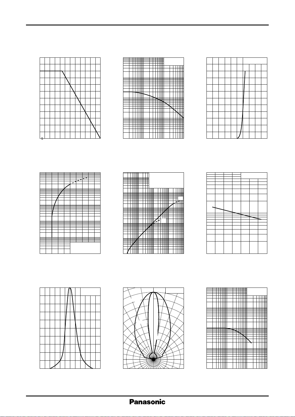
I
— Ta
120
100
(mA)
F
80
60
40
20
Allowable forward current I
0
– 25
F
0 20406080100
Ambient temperature Ta (˚C )
I
— V
10
10
(mA)
FP
10
10
4
3
2
FP
I
— Duty cycle
FP
2
10
10
(A)
FP
1
–1
10
Pulse forward current I
–2
10
–1
10
11010
tw = 10µs
Ta = 25˚C
120
100
(mA)
F
Forward current I
2
80
60
40
20
0
0 0.4 0.8 1.2 2.01.6
Duty cycle (%)
∆P
— I
F
3
10
O
2
10
10
1
O
FP
(1) t
= 10µs
w
Duty Cycle = 0.1%
(2) DC
Ta = 25˚C
(1)
(2)
10
O
1
I
— V
F
F
Ta = 25˚C
Forward voltage VF (V)
∆P
— Ta
O
IF = 100mA
1
Pulse forward current I
–1
10
0
13524
tw = 10µs
Duty Cycle = 0.1%
Ta = 25˚C
Forward voltage VF (V)
Spectral characteristics
100
80
60
40
Relative radiant intensity (%)
20
0
850 900 950 1000 1050 1100
800
Wavelength λ (nm)
I
= 100mA
F
Ta = 25˚C
Relative radiant power ∆P
–1
10
–2
10
110
2
10
Pulse forward current IFP (mA)
Directivity characteristics
LN51F
LN51L
0˚ 10˚ 20˚
100
90
80
70
60
50
40
30
20
Relative radiant power ∆P
4
30˚
40˚
50˚
60˚
Modulation output
70˚
80˚
90˚
10
10
10
3
10
10
Ta = 25˚C
Relative radiant intensity(%)
–1
– 40 0 40 80
Ambient temperature Ta (˚C )
Frequency characteristics
2
10
10
1
–1
–2
10
2
10
Frequency f (kHz)
3
10
Ta = 25˚C
4
10
2
 Loading...