

Infrared Light Emitting Diodes
,
LN189L
GaAlAs Infrared Light Emitting Diode
Light source for distance measuring systems
Features
High-power output, high-efficiency : PO = 5.5 mW (typ.)
Fast response and high-speed modulation capability :
Infrared light emission close to monochromatic light :
Narrow directivity using spherical lenses; works well with optical
systems in auto focus systems
Mini hollow mold resin package
Absolute Maximum Ratings (Ta = 25˚C)
Parameter Symbol Ratings Unit
Power dissipation P
Forward current (DC) I
Pulse forward current I
Reverse voltage (DC) V
Operating ambient temperature
Storage temperature T
*
f = 10 kHz, Duty cycle = 25 %
D
F
*
FP
R
T
opr
stg
190 mW
100 mA
0.2 A
–25 to +85 ˚C
– 40 to +100 ˚C
tr, tf = 20 ns (typ.)
λP = 880 nm(typ.)
3V
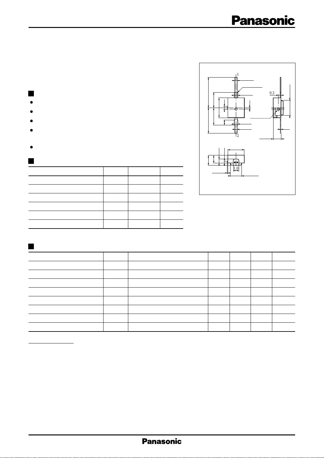
6.0±0.35.0±0.3
2.0±0.2
3.0±0.2
4.0±0.15
3.4±0.2
0.75
1.5
0.1 max.
0.60.35
1.0
3.2±0.15
1.0
1
2
0.4±0.1
0.6±0.1
0.6±0.1
0.5±0.1
Mark (Red)
0.2
Spherical lens
ø0.55±0.05
2.2±0.15
1.5±0.2
Unit : mm
0.38
1: Anode
2: Cathode
3.0±0.15
0.15
Electro-Optical Characteristics (Ta = 25˚C)
Parameter Symbol Conditions min typ max Unit
Radiant power
Peak emission wavelength λ
PO IF
P
Spectral half band width ∆λ IF = 100mA 50 nm
Forward voltage (DC) V
Reverse current (DC) I
Rise time t
Fall time t
F
R
r
f
Half-power angle θ
Precautions for Use
[Airtightness] This product is not structured to provide a complete air seal. Therefore it cannot be immersed in solutions for
purposes such as boiling tests or ultrasonic cleaning.
[Ability to withstand soldering heat]
[Ability to withstand chemicals]
The package of this product contains thermoplastic resin which has a limited ability to withstand heat. Therefore
this product cannot be put through automated soldering operations in which the ambient temperature exceeds
the specified temperature. The recommended soldering conditions are as follows.
· Temperature of soldering iron tip : 260˚C or less
· Soldering time : 5 seconds or less : 1 second or less
· Soldering position : At least 2 mm away from lead base
If the transparent case requires cleaning, wipe it lightly using ethyl alcohol, methyl alcohol, or isopropyl alcohol.
If you plan to use other solvents, carefully check to make sure there are no problems such as a misshapen case or
a change in the condition of the case material.
= 100mA 3 5.5 mW
IF = 100mA 880 nm
IF = 100mA 1.55 1.9 V
VR = 3V 10 µA
I
= 100mA 20 ns
FP
I
= 100mA 20 ns
FP
The angle in which radiant intencity is 50%
: 300˚C or less
or
]
20 deg.
1
LN189L Infrared Light Emitting Diodes
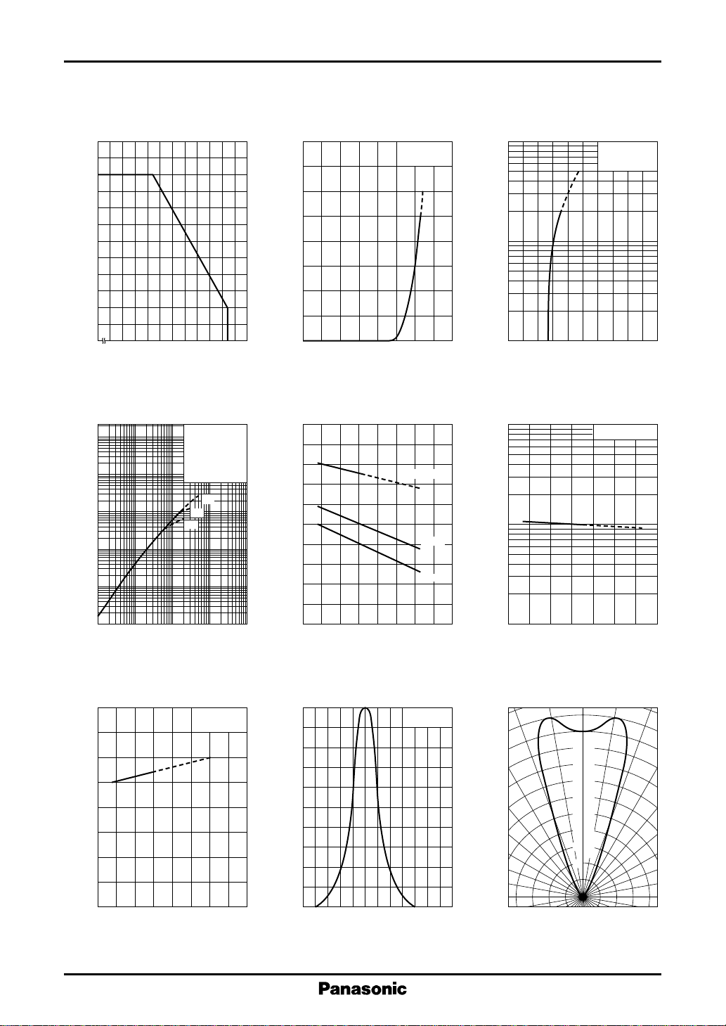
I
— Ta
120
100
(mA)
F
80
60
40
20
Allowable forward current I
0
– 25
F
0 20406080100
Ambient temperature Ta (˚C )
∆P
— I
O
3
10
O
2
10
10
1
F
(1) tw = 10µs
Duty = 0.1%
(2) tw = 50µs
Duty = 50%
(3) DC
Ta = 25˚C
(1)
(2)
(3)
I
— V
F
160
140
120
(mA)
F
100
80
60
40
Forward current I
20
0
0 0.5 1.0 1.5 2.0
F
Forward voltage VF (V)
V
— Ta
F
(V)
F
1.8
1.6
1.4
1.2
Ta = 25˚C
IF = 100mA
10mA
I
FP
(A)
FP
10
1
–1
Pulse forward current I
–2
10
0
13524
Forward voltage VF (V)
∆P
10
O
1
O
— V
F
t
= 10µs
w
f = 100Hz
Ta = 25˚C
— Ta
IF = 100mA
Relative radiant power ∆P
–1
10
–2
10
–3
–2
10
10
–1
10
1
Forward current IF (A)
λ
— Ta
1000
(nm)
900
P
800
700
P
IF = 100mA
Peak emission wavelength λ
600
– 40 0 40 80 120
Ambient temperature Ta (˚C )
Forward voltage V
1.0
10
0.8
– 40 0 40 80 120
Ambient temperature Ta (˚C )
Spectral characteristics
100
80
60
40
Relative radiant intensity (%)
20
0
780
1mA
I
= 100mA
F
820 860 900 940 980 1020
Wavelength λ (nm)
Relative radiant power ∆P
–1
10
– 40 0 40 80
Ambient temperature Ta (˚C )
Directivity characteristics
0˚ 10˚ 20˚
100
90
80
70
60
50
40
30
Relative radiant intensity (%)
20
30˚
40˚
50˚
60˚
70˚
80˚
90˚
2
 Loading...