

Page 1
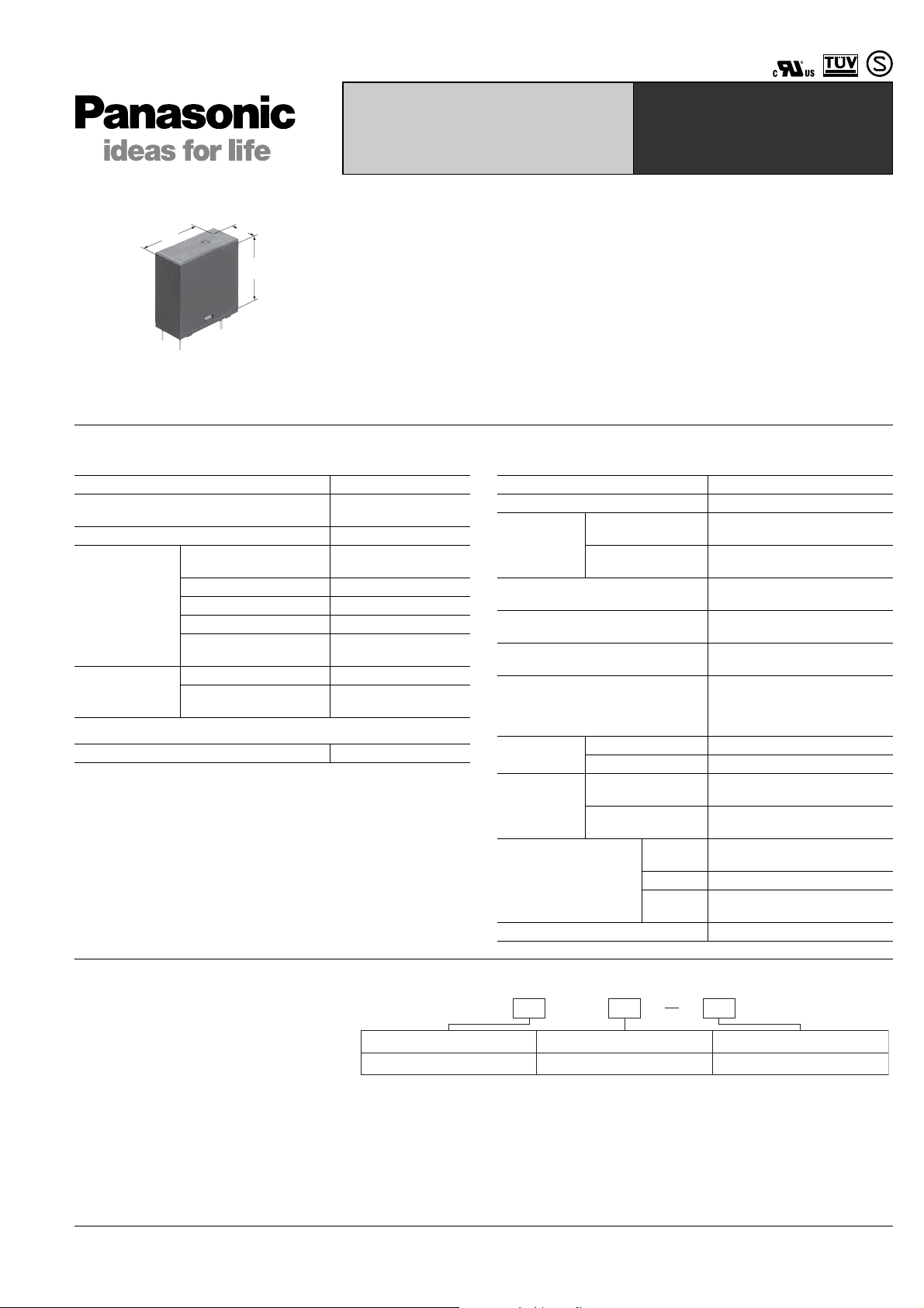
SLIM POWER RELAY
WITH HIGH INRUSH
CURRENT CAPABILITY
TV-8 CERTIFIED
LK-T
LK-T RELAYS
24.0
.945
11.0
.433
25.0
.984
FEATURES
1. High inrush current capability
1) Operating load capability:
inrush 118 A, steady 8 A
2) UL/C-UL TV-8 approved
2. High insulation resistance
1) Creepage distance and clearances
between contact and coil: Min. 6 mm .236
inch (In compliance with IEC65)
2) Surge withstand voltage between
contact and coil: 10,000 V or more
SPECIFICATIONS
Contact
Arrangement 1 Form A
Initial contact resistance
(By voltage drop 6 V DC 1 A)
Contact material AgSnO2 type
Nominal switching
capacity
Rating
(resistive load)
Expected life
(min. operations)
Max. switching power 1,385 V A
Max. switching voltage 277 V AC
Max. switching current 8 A (120V AC)
Min. switching capacity
(Reference value)
Mechanical (at 180 cpm) 10
Electrical (at 20 cpm)
(at rated load)
#1
Coil
Nominal operating power 250 mW
#1 This value can change due to the switching frequency , environment al conditions,
and desired reliability level, therefore it is recommended to check this with the
actual load.
Remarks
*1Measurement at same location as “Initial breakdown voltage” section.
2
Detection current: 10mA
*
3
Wave is standard shock voltage of ±1.2 × 50μs according to JEC-212-1981
*
4
Excluding contact bounce time.
*
5
Half-wave pulse of sine wave: 11 ms; detection time: 10 μs
*
6
Half-wave pulse of sine wave: 6 ms
*
7
Detection time: 10 μs
*
8
The upper operation ambient temperature limit is the ma ximum t emperature t hat
*
can satisfy the coil temperature rise value. Refer to 1. Usage, transport and
storage conditions in NOTES on page 3.
Max. 100 mΩ
5 A 277 V AC
100 mA, 5 V DC
6
5
10
3. High noise immunity realized by the
card separation structure between
contact and coil
4. Conforms to the various safety
standards
UL, C-UL, TÜV, and SEMKO approved
Characteristics
Max. operating speed 20 cpm (at rated load)
Initial insulation resistance*
Initial *2
breakdown
voltage
Initial surge voltage between contact
and coil*
Operate time*
(at nominal voltage)
Release time (without diode)*
(at nominal voltage)
Temperature rise (at 70°C)
Shock
resistance
Vibration
resistance
Conditions for operation,
transport and storage*
(Not freezing and
condensing at low
temperature)
Unit weight Approx. 12 g .42 oz
Between open
contacts
Between contact
and coil
3
4
Functional*
Destructive*
Functional*
Destructive
1
4
5
6
7
Ambient
temp.
8
Humidity 5 to 85% R.H.
Air
pressure
Min. 1,000 MΩ (at 500 V DC)
1,000 Vrms for 1 min.
4,000 Vrms for 1 min.
10,000 V
Max. 15ms (at 20°C 68°F)
Max. 5ms (at 20°C 68°F)
Max. 35°C with nominal coil
voltage and at 5 A contact
carrying current
(resistance method)
200 m/s2{approx. 20 G}
1,000 m/s2{approx. 100 G}
10 to 55Hz
at double amplitude of 1.5mm
10 to 55Hz
at double amplitude of 1.5mm
–40°C to +70°C
–40°F to +158°F
86 to 106 kPa
TYPICAL
APPLICATIONS
• Audio visual equipment
• Flat TVs and audio equipment, etc.
• Office equipment
• Home appliances
ds_61113_0004_en_lkt: 091008J
ORDERING INFORMATION
Ex. LKT 1a F 12V
Contact arrangement Protective construction Coil voltage(DC)
1a: 1 Form A F: Flux-resistant type 5, 9, 12, 24V
UL/C-UL, TÜV, SEMKO, TV-8 approved type is standard.
Notes: 1. Standard packing Carton: 100 pcs. Case: 500 pcs.
2. 3 V, 6 V, and 18 V DC types are also available. Please consult us for details.
1
Page 2
LK-T
2-0.9 dia. 2-1.3 dia.
2
a.
A
TYPES AND COIL DATA (at 20°C 68°F)
Drop-out
voltage,
V DC (min.)
(Initial)
Coil resistance,
Ω (±10%)
Part No.
Nominal voltage,
V DC
Pick-up voltage,
V DC (max.)
(Initial)
LKT1aF-5V 5 (Initial) 3.5 (Initial) 0.5 100 50 250 6.5
LKT1aF-9V 9 (Initial) 6.3 (Initial) 0.9 324 27.8 250 11.7
LKT1aF-12V 12 (Initial) 8.4 (Initial) 1.2 576 20.8 250 15.6
LKT1aF-24V 24 (Initial) 16.8 (Initial) 2.4 2,304 10.4 250 31.2
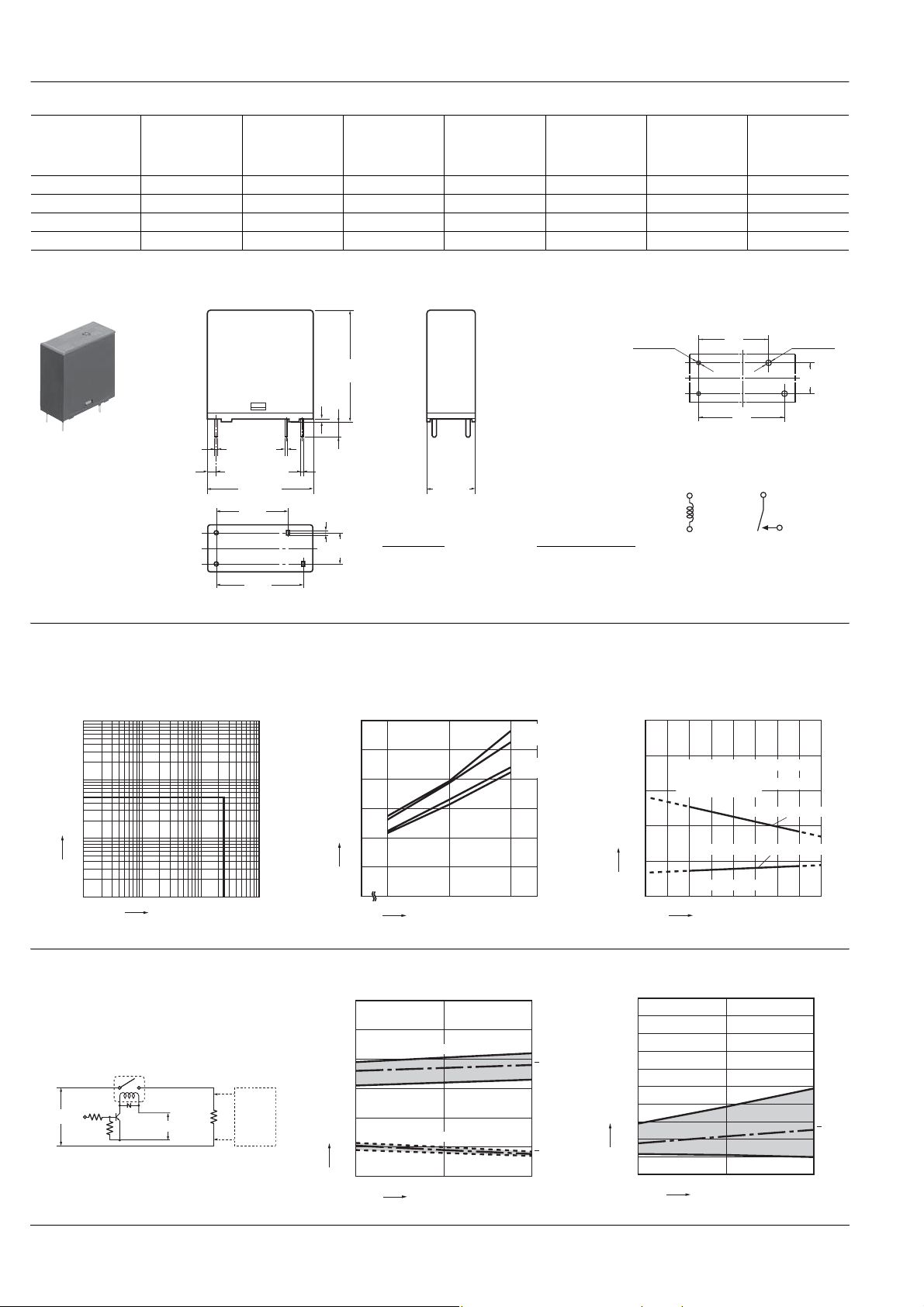
DIMENSIONS
Max. 25.0
.984
0.5
.020
4
0.4
.016
1.0
.039
7.5
.295
.157
Max. 11.0
.433
Dimension: General tolerance
Max. 1mm .039 inch: ±0.1 ±.004
1 to 3mm .039 to .118 inch: ±0.2 ±.008
Min. 3mm .118 inch: ±0.3 ±.012
0.5 dia.
.020 dia.
1.65
.065
0.3
.012
Max. 24.0
.945
16.5
.650
20.0
.787
Nominal
operating
current, mA
(±10%)
Nominal
operating power,
mW
PC board pattern (Bottom view)
-.035 dia. 2-.051 di
16.5
.650
20.0
.787
Tolerance: ±0.1 ±.004
Schematic (Bottom view)
Maximum
allowable
voltage, V DC
(at 20°C 68°F)
mm inch
7.5
.295
REFERENCE DATA
1. Max. switching power (AC resistive load) 2. Coil temperature rise
100
10
5
Contact current, A
1
0 10 100
Contact voltage, V
4-(1). Electrical life test
(5 A 277 V AC, resistive load)
Sample: LKT1aF-12V, 6 pcs.
Operation frequency: 20 times/min.
(ON/OFF = 1.5s: 1.5s)
Ambient temperature: 20°C 68°F
Circuit:
Contact
welding
detection
277V AC
12V DC
and Miscontacting
detection
circuit
2
Sample: LKT1aF-12V, 6 pcs.
Point measured: coil inside
Contact current: 0 A, 5A
30
25
20
15
Temperature rise, °C
10
5
0
Change of pick-up and drop-out voltage Change of contact resistance
12
10
8
6
4
Pick-up and drop-out voltage, V
2
0
0
800
100 120
Coil applied voltage, %V
Pick-up voltage
Drop-out voltage
510
No. of operations, ×10
4
20°C 5A
20°C 0A
70°C 5A
70°C 0A
Max.
x
Min.
Max.
x
Min.
3. Ambient temperature characteristics and coil
applied voltage
500
400
300
200
Coil applied voltage, %V
100
50
45
40
35
30
25
20
Contact resistance, mΩ
15
10
5
0
Allowable ambient temperatures
against % coil voltages
(max. inside the coil temperature
set as 115°C
0
0 1020304050607080
0
239°F)
Carrying current: 5
Coil & contact no carrying current
Pick-up voltage
Ambient temperature, °C
105
No. of operations, ×10
4
Max.
x
Min.
ds_61113_0004_en_lkt: 091008J
Page 3

4-(2). Electrical life test
(UL508 TV-8 rating test)
Sample: LKT1aF-12V, 6 pcs.
• Overload test
Load: 12 A 120 V AC (60 Hz),
Inductive load (cosφ = 0.75)
Operation frequency: 6 times/min
(ON : OFF = 1 s : 9 s)
No. of operations: 50 ope.
• Endurance test
Load: 8A 120 V AC (960 W lamp load),
(Inrush: 118 A)
Operation frequency: 1 times/min
(ON: OFF = 1 s: 59 s)
No. of operations: 25,000 ope.
NOTES
1. Usage, transport and storage
conditions
1) Temperature:
–40 to +70°C –40 to +158°F
2) Humidity: 5 to 85% RH
(Avoid freezing and condensation.)
The humidity range varies with the
temperature. Use within the range
indicated in the graph below.
3) Atmospheric pressure: 86 to 106 kPa
Temperature and humidity range for
usage, transport, and storage
Humidity, %RH
85
Tolerance range
(Avoid freezing
when used at
temperatures lower
than 0°C
4) Condensation
Condensation forms when there is a
sudden change in temperature under
high temperature and high humidity
conditions. Condensation will cause
deterioration of the relay insulation.
5) Freezing
Condensation or other moisture may
freeze on the relay when the
temperatures is lower than 0°C 32°F.
This causes problems such as sticking of
movable parts or operational time lags.
6) Low temperature, low humidity
environments
The plastic becomes brittle if the relay is
exposed to a low temperature, low
humidity environment for long periods of
time.
(Avoid
condensation
when used at
temperatures higher
32°F)
than 0°C 32°F)
5
070-40
+32 +158-40
Temperature, °C °F
Change of pick-up and drop-out voltage Change of contact resistance
12
10
8
6
4
Pick-up and drop-out voltage, V
2
0
025
Pick-up voltage
Drop-out voltage
No. of operations, ×10
Max.
x
Min.
Max.
x
Min.
3
2. Solder and cleaning conditions
1) Please obey the following conditions
when soldering automatically.
(1) Preheating: Within 120°C 248°F
(solder surface terminal portion) and
within 120 seconds
(2) Soldering iron: 260°C±5°C
500°F±41°F (solder temperature) and
within 6 seconds (soldering time)
2) Since this is not a sealed type relay, do
not clean it as is. Also, be careful not to
allow flux to overflow above the PC board
or enter the inside of the relay.
3. Certification
1) This relay is UL and C-UL certified
(File No. E43149).
UL, C-UL rating: TV-8
2) This relay is certified by TUV as an
electromagnetic relay that complies with
VDE0435 (File No. B040413461035).
(1) TUV rating: 8A, 250 V to COSφ = 1.0
(2) The terminals of this relay can only be
connected with solder.
(3) This relay is certified by SEMKO (File
No. 400968).
SEMKO rating: 3/100A 250 V AC, 5/40A
250 V AC
4. Others
1) For precautions regarding use and
explanations of technical terminology,
please refer to “Relay Technical
Information”.
2) T o ensure good operation, please keep
the voltage on the coil ends to ±5% (at
20°C 68°F) of the rated coil operation
voltage. Also, please be aware that the
pick-up voltage and drop-out voltage may
change depending on the temperature
and conditions of use.
3) Keep the ripple rate of the nominal coil
50
45
40
35
30
25
20
Contact resistance, mΩ
15
10
5
0
0
No. of operations,
4) The cycle lifetime is defined under the
standard test condition specified in the
JIS* C 5442 standard (temperature 15 to
°C 59 to 95°F, humidity 2 5 to 75%).
35
Check this with the real device as it is
affected by coil driving circuit, load type,
activation frequency, activation
phase,ambient conditions and other
factors.
Also, be especially careful of loads such
as those listed below.
(1) When used for AC load-operating and
the operating phase is synchronous.
Rocking and fusing can easily occur due
to contact shifting.
(2) High-frequency load-operating
When high-frequency opening and
closing of the relay is performed with a
load that causes arcs at the contacts,
nitrogen and oxygen in the air is fused by
the arc energy and HNO
can corrode metal materials.
Three countermeasures for these are
listed here.
• Incorporate an arc-extinguishing circuit.
• Lower the operating frequency
• Lower the ambient humidity
5) Heat, smoke, and even a fire may
occur if the relay is used in conditions
outside of the allowable ranges for the
coil ratings, contact ratings, operating
cycle lifetime, and other specifications.
Therefore, do not use the relay if these
ratings are exceeded.
6) If the relay has been dropped, the
appearance and characteristics should
always be checked before use.
7) Incorrect wiring may cause
unexpected events or the generation of
heat or flames.
voltage below 5%.
LK-T
Max.
x
Min.
25
3
×10
3 is formed. This
For Cautions for Use, see Relay Technical Information.
ds_61113_0004_en_lkt: 091008J
3
 Loading...