

Panasonic LCD-2016 Technical Manual
Model No. LCD-2016
2016 - LCD TV
Circuit Operation and Troubleshoot
c Panasonic Corporation 2016
Unauthorized copying and distribution is
a violation of law.
1

INDEX
1.Board Layout
2.Video Signal Processing
3.Power Supply
3-1. Power Board Structure
3-2. Stand by / Start up Operation
4.SOS Protection Circuit and Troubleshooting (except 1 time blink)
5.Difference of LED Drive Circuit (Troubleshooting for 1 time blink)
2

1. Board Layout
3
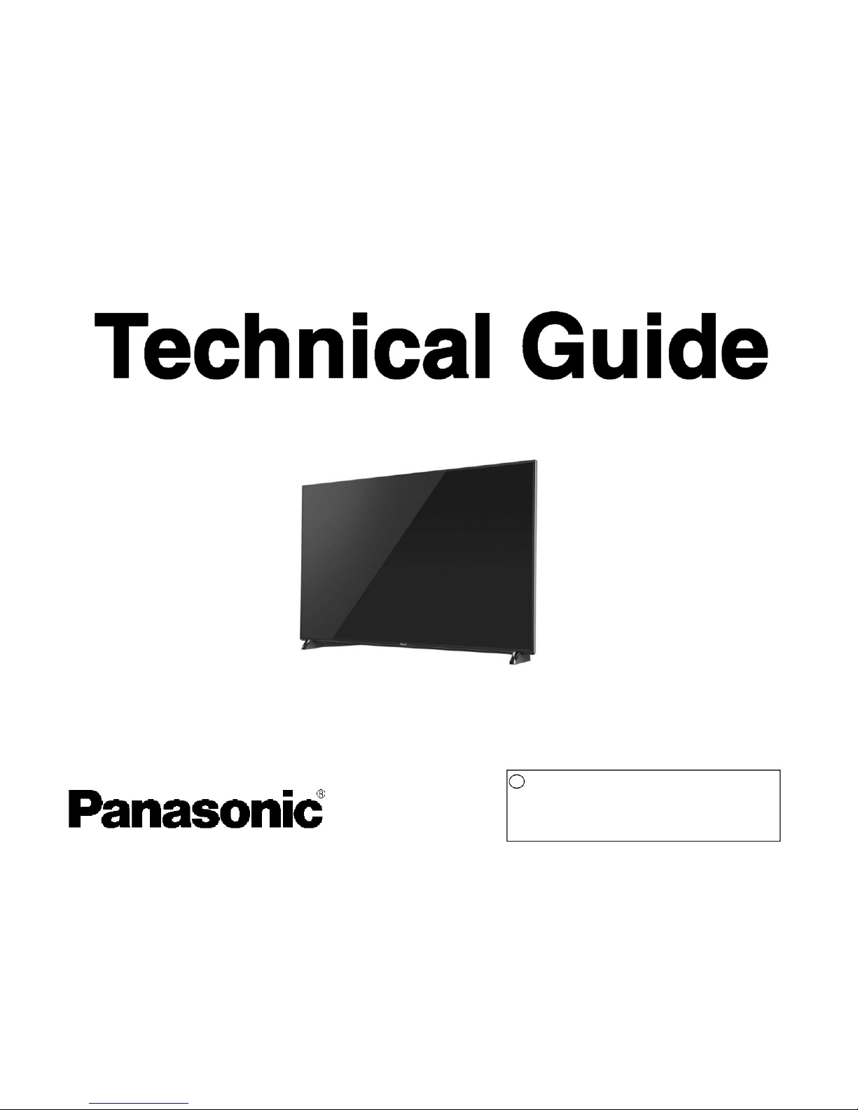
Board Layout -1 ( DX*** series )
T*-**DX900
G
P PB A
K
K
T*-65DX***, TH/TC-55DX***
G P PB A
K
K
T*-40DX*** T*-49/50/58DX***, TX-55DX***
LDP
G
P
A
G
P
A
K K
K K
GK board : depend on the model BT : depend on the model and region
4
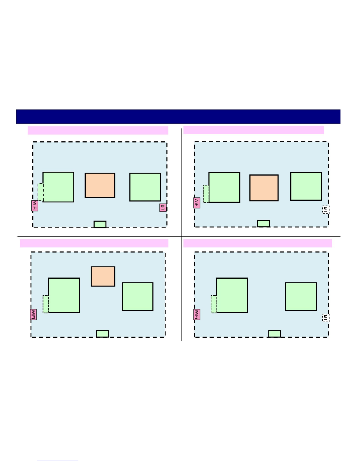
Board Layout -2 ( D/DS*** series )
T*-49/43DS*** T*-65/55DS***
T*-
49/43D***
LD
LDP
G
P
A
G
P
A
K
K
K K
T*-50/40/32DS***
T*-40/32D***
P
G A
K
TH-32D400
A
(P + A + GK)
K K
WiFi : only DS*** series
BT : only TC-**DS6**, TX-**DS630 series GK board : depend on the model
5
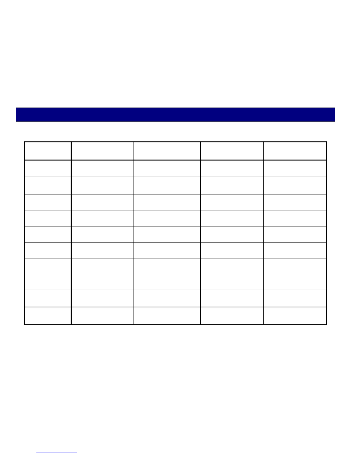
Main Board Structure
D4** DS6** DX6**/7**/8** DX900
(4K) (4K)
32inch A+P / A+P --- ---
40inch A+P A+P A+P+LDP ---
43inch A+P+LD A+P+LD --- ---
49inch A+P+LD A+P+LD A+P ---
50inch --- A+P A+P ---
55inch --- A+P+LDP A+P , ---
A+P+PB: (only
TH-55DX640*,
TC-55DX700*)
58inch --- --- A+P A+P+PB
65inch --- A+P+LDP A+P+PB A+P+PB
Except K, GK boards
6
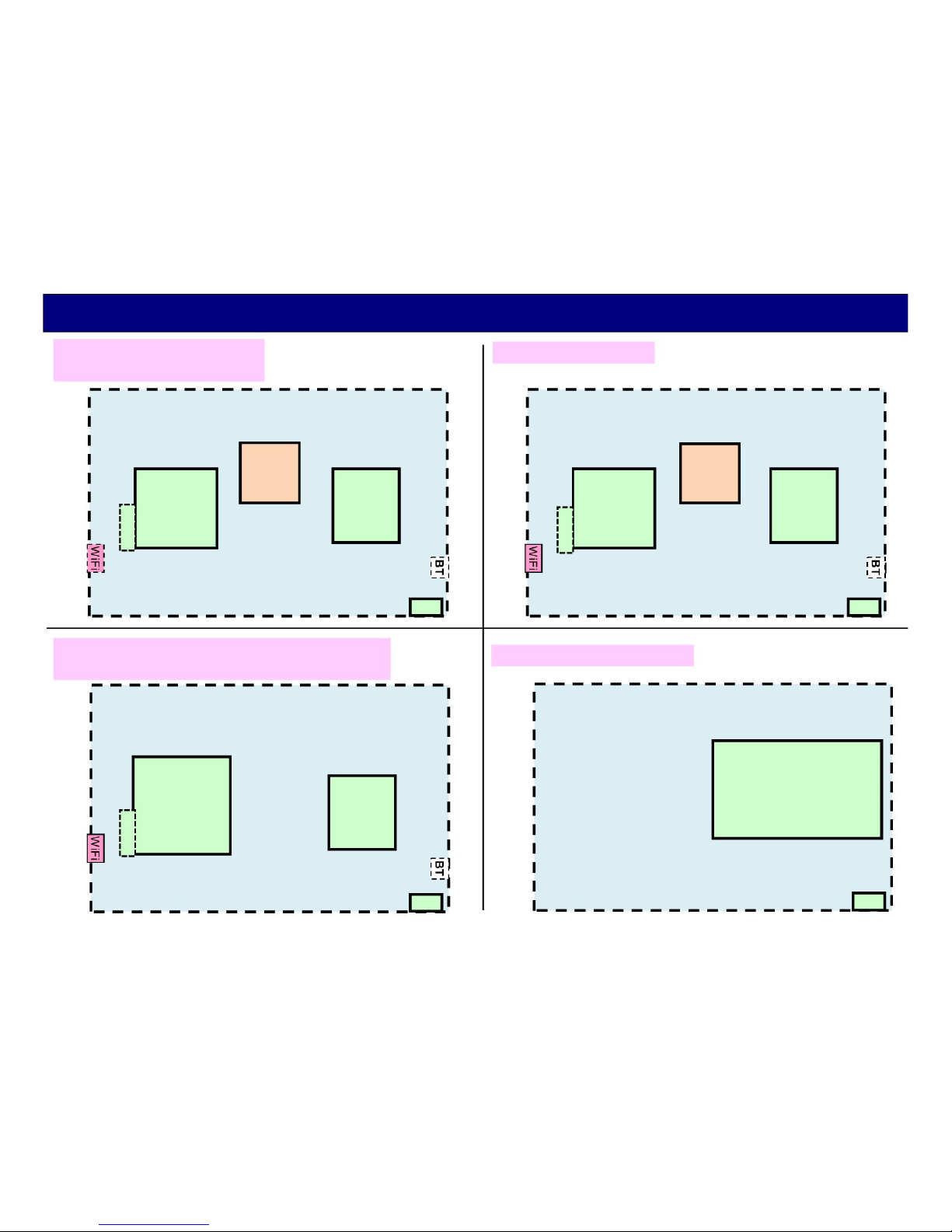
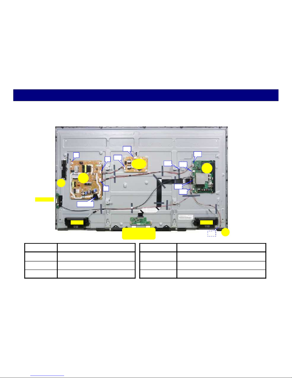
Board Layout -1
A+P
P3
P
A15
A10
AC input
Speaker
( 32D400 )
A02
A
A12
Speaker
K10
K
Board Name Function
A-Board Main Board
P-Board Power supply, Backlight Drive, Power key, Control key
K-Board Remote Receiver, LED
7
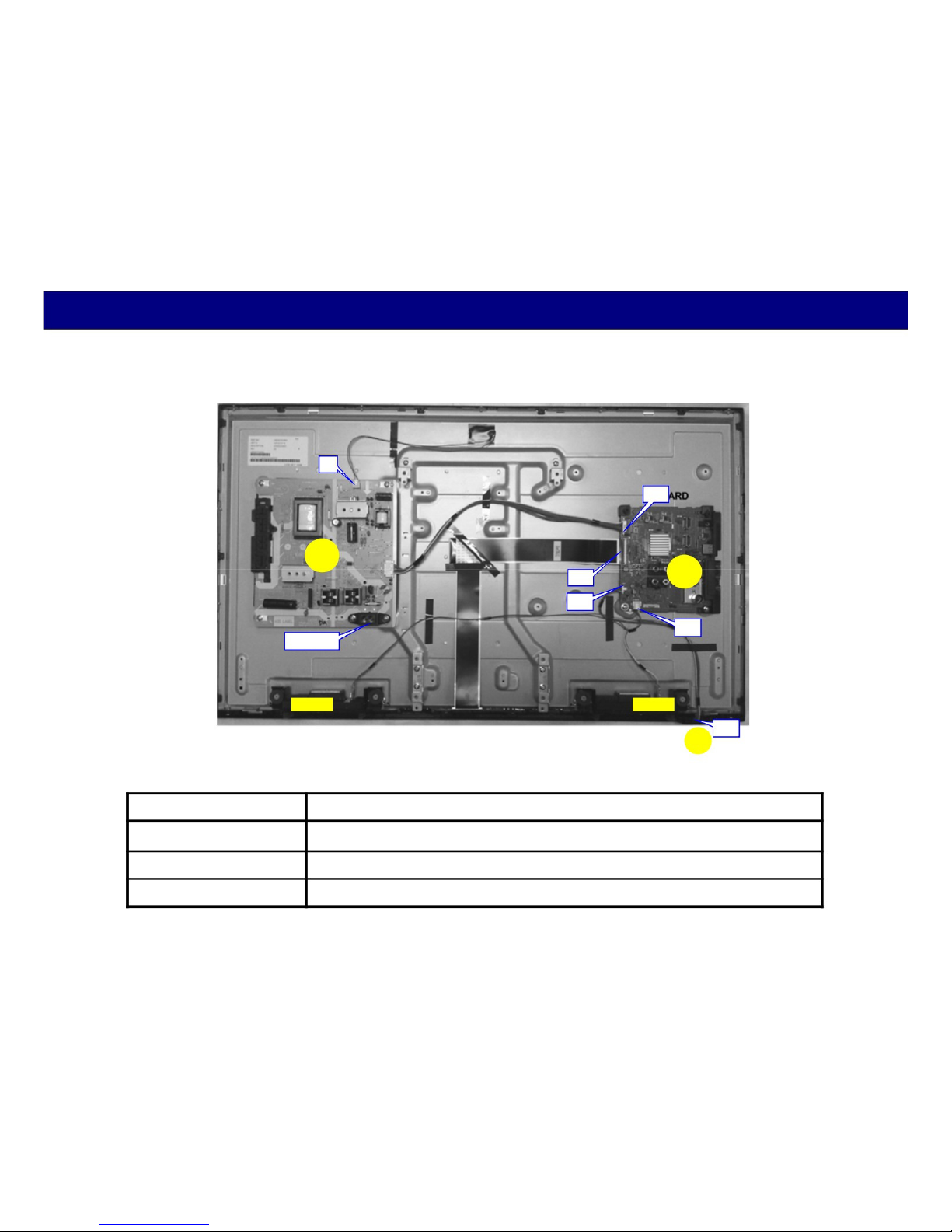
Board Layout -2
A+P+LD/LDP
P5
P4
P
GK
P2
WiFi Module
AC input
Speaker
LD2
LD1
LD A15 A10
A19
A12
(T-CON)
Not repairable,
One of the panel module
( 49DS630 )
A02
A
Speaker
K10 K
Board Name Function Board Name Function
A-Board Main Board GK-Board Key
P-Board Power supply for Signal Process K-Board Remote Receiver, Power LED
LD-Board Power supply for Backlight Drive
8
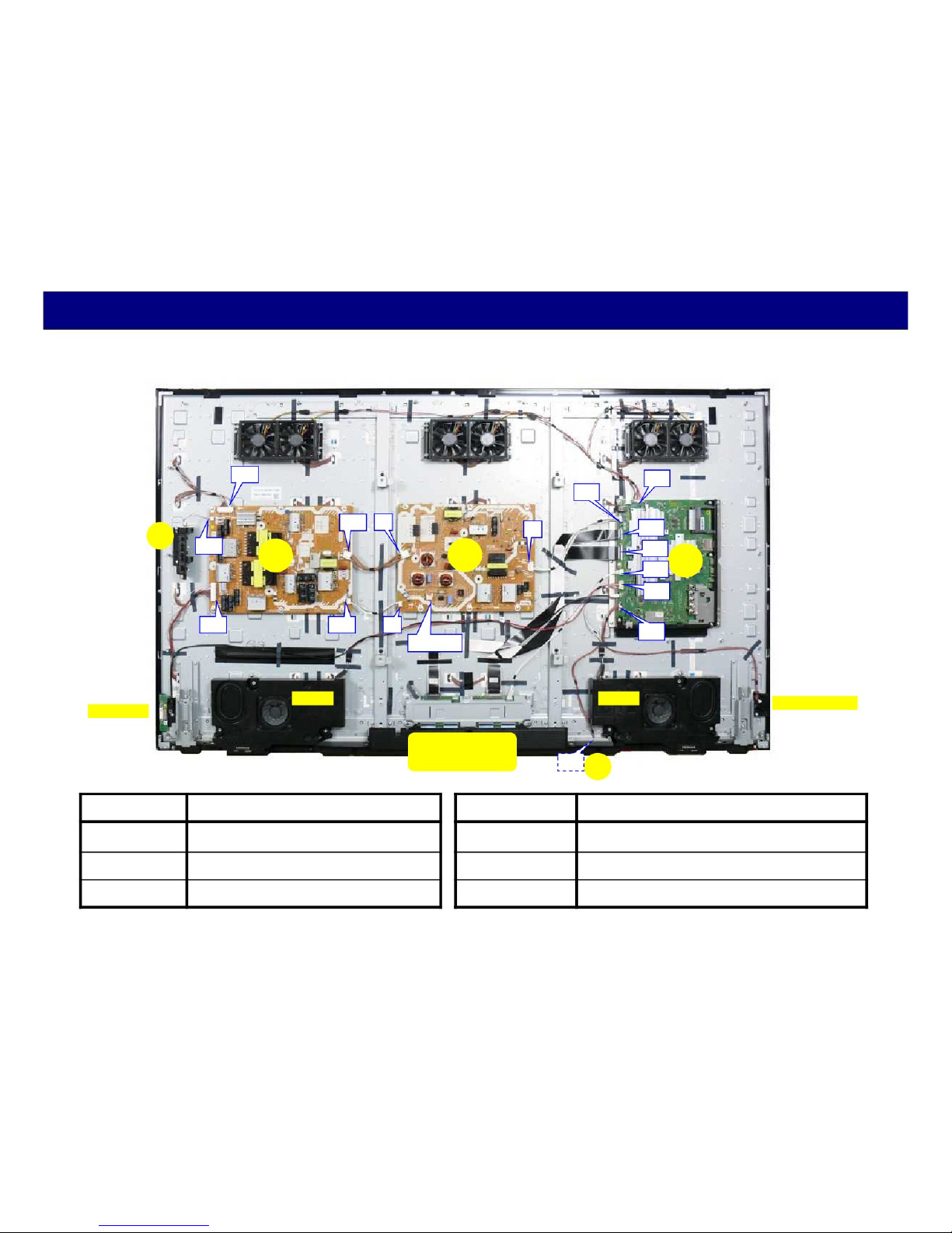
Board Layout -3
GK
A+P+PB
PB1
PB6 P6
PB5
( 65DX900 )
A08
A02
P2 A15
A16
PB2
WiFi Module
PB
PB3 P3
Speaker
P
AC input
(T-CON)
Not repairable,
One of the panel module K10
A17
A12
A10
Speaker
K
A
Bluetooth Module
Board Name Function Board Name Function
A-Board Main Board GK-Board Key
P-Board Power supply for Signal Process K-Board Remote Receiver, Power LED
PB-Board Power supply for Backlight Drive
9

2. Video Signal Processing
10
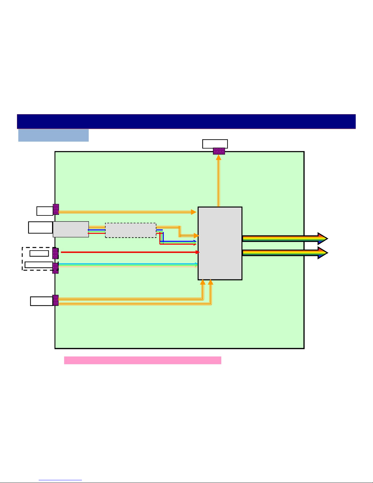
Video/Audio Signal Process - 1
D4** series
OPT_out
A
USB1
Antenna
terminal
AV
Component
HDMI1/2
TU670*
TUNER
IC68**
De-Modulation
IC8000
(
MTK5561)
Resize
IP conv.
OSD
LVDS Data
to LCD Panel
The input terminals are different by the models or countries.
11

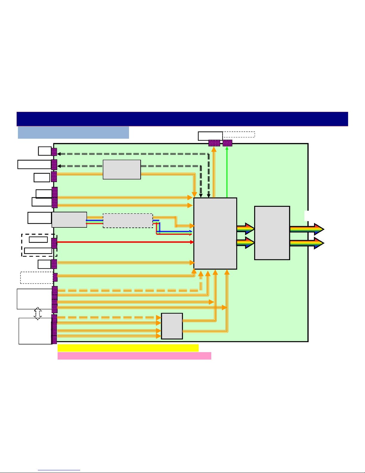
Video/Audio Signal Process - 2
DS6** series
WiFi
Bluetooth
USB1/2
Antenna TU670*
terminal TUNER
AV
Component
LAN
HDMI1/2/3
IC8601
(USB HUB)
IC68**
De-Modulation
IC8650
(LAN)
OPT_out
IC8000
(
Peaks LD6/
sLD8A)
Resize
IP conv.
OSD
A
LVDS Data
to LCD Panel
The input terminals are different by the models or countries.
12
SCART
(Europe)
CI - slot
(Europe)
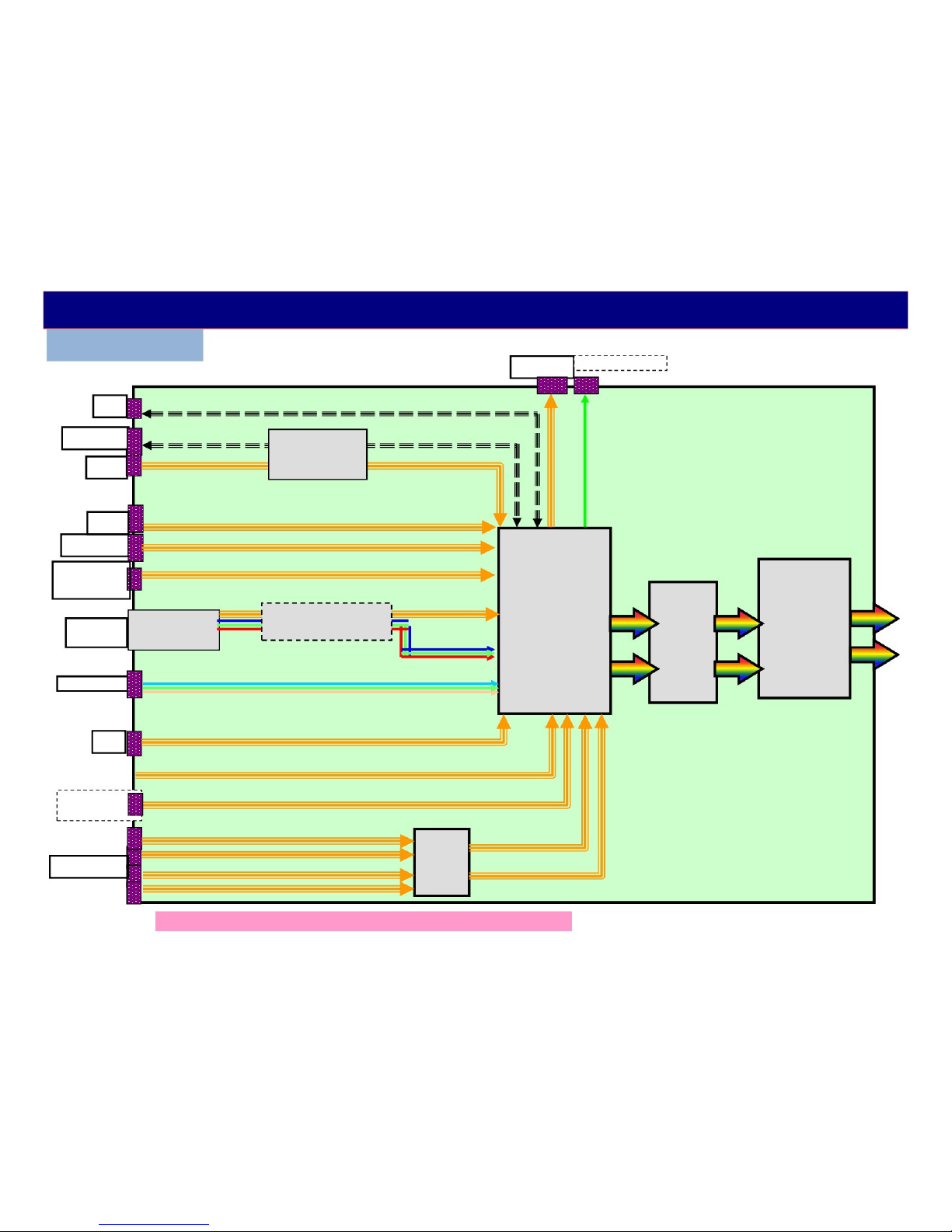
Video/Audio Signal Process - 3
DX6** / DX7** / DX8** series
WiFi
OPT_out
(*1)Bluetooth
IC8601
USB2
USB1
USB3.0
Antenna
terminal
AV
Component
LAN
(USB HUB)
TU670* IC68**
TUNER De-Modulation
IC8000
(
MT5810) IC9000
(Mstar/NTK)
Resize
IP conv. Frame Rate
OSD Convert
2D->3D
A
to LCD Panel
( V by One format )
HDMI1/2/3/(4)
(except below
models
HDMI1/2/3/(4)
(TX-DX8**
TH-DX640
TC-DX700C)
IC4500
HDMI
SW
(*1) Bluetooth : only DX9**/7** (except TC-**DX700C)
The input terminals are different by the models or countries.
13
CI - slot
(Europe)
Video/Audio Signal Process - 4
DX900 series
WiFi
Bluetooth
USB2
USB1
USB3(3.0)
SD card
(only TC/TX
Antenna TU670*
OPT_out
IC8705
(USB HUB)
IC8000
(
MT5810)
IC4300
IC68** Resize (GCEX2)
De-Modulation IP conv.
IC9000
(NTK)
A
to LCD
Panel
terminal TUNER
Component
LAN
HDMI1/2/3/4
OSD HDR
2D->3D Hexa-
chroma
IC4500
HDMI
SW
Frame Rate
Convert
( V by One format )
(*) The input terminals are different by the models or countries.
14

Video/Audio Signal Process - 5
The main function of the A board is to select and process one of the incoming video signals.
IC8601 ( or IC8705) is just switches of USB signals. The built in WiFi module is connected by
USB type of terminal.
Video input, Component Video Input, HDMI input and the composite video output of the tuner
are all connected to IC8000 for selection. The video input signal can be two formats: Video, or Y,
Pb, Pr. A comb filter inside IC8000 converts the composite video signal of the main picture to Y
and C (luminance and chrominance) signals. The signal is then converted to RGB. At the
completion of this process, the format of the composite signal is now the same as a digital 1080i
component signal. If the incoming video is in the 480p, 720p, 1080i, and 1080p format, the Y, Pb,
and Pr signals undergo A/D (analog to digital) conversion. Finally all picture signals are
converted to 1080p.
Digital television reception of the tuner is output in the form of an IF (Intermediate Frequency)
signal. The transport stream from the tuner enters the VSB I/F (Interface) section of IC8000 where
the video signal is extracted and converted to YUV data. The output is provided to the Video Input
I/F for selection. The JPEG data of the SD card enters the JPEG I/F section of IC8000 for
conversion into YUV data and output to the Video Input I/F circuit. The video input interface
outputs the selected picture data to the video process circuit.
This Video Process section of the IC performs all picture control operations such as brightness,
contrast, color, tint, etc. On Screen Display data such as channel numbers, Digital TV closed
caption, and picture adjustments are mixed with the video data. If in 3D mode, it converts to the
right and left pictures. After the process, LVDS (Low Voltage Differential Signaling) is output to
LCD panel module. # IC9000 is the frame rate converting IC for high speed LCD panel. IC4300
adjust the brightness for HDR feature.
15

Troubleshoot for Video Signal Problem
<LCD Panel Test Mode> :When abnormal picture is displayed, troubleshoot by the test pattern in LCD module.
If the picture is no problem, A board must be defective.
If the picture is also abnormal, LCD panel module must be defective. Just in
case, confirm the flat cable connection between A board and T-CON board.
How to enter :
While pressing "volume(-)" button of the TV unit,
press "option/yellow" button of the remote control 3 times within 2 seconds.
How to exit :
Switch off the TV unit
#)The test pattern is created by the circuit in LCD Panel Module(T-CON board).
A LCD Panel Module
IC8000 LCD Panel
Some patterns are
automatically changed.
The patterns are depend
on the LCD panel.
(Peaks/MTK )
Resize
IP conv.
T-CON
Test
Pattern
16
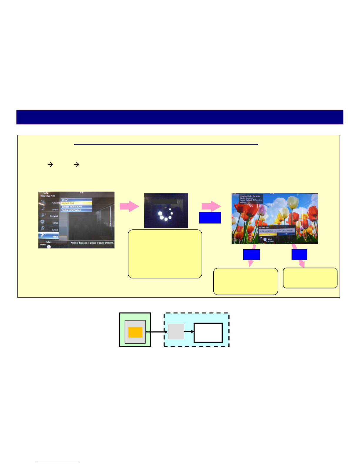
Troubleshoot for Video/Audio Signal Problem
<TV Self Test> : Customers also can check the picture and sound by internal data.
If the picture and sound is no problem, the reason of trouble is mostly not a TV.
How to display :
Menu HELP TV Self Test
#)The test pattern and test sound are created by the main IC on the A board.
TV Self Test
(OK)
1) During this indication
“Self Check of Service Mode”
is working at the background.
*) does not apply to D400/410 series
2) If NG, indication is shown.
# A board defective
3) If All OK, it shifts to picture
and sound test.
Yes
1.Antenna level low
2.Connection mistake
3.Input devices NG
4.Input select mistake
No
TV unit defective.
(A board, Panel or
Speaker)
A
IC8000
Test
Pattern
IP conv.
LCD Panel Module
T-CON LCD Panel
17

3. Power Supply
3-1. Power Board Structure
18
 Loading...