

Panasonic KX-TS3282B, KX-TS3282W User Manual
Integrated Telephone System
Operating Instructions
Model No. KX-TS3282B
KX-TS3282W
Pulse-or-tone dialing capability
Basic Operation Useful InformationAdvanced OperationPreparation
INTERCOM
KX-TS3282W
2 LINE Caller ID Compatible
PLEASE READ BEFORE USE AND SAVE.
Panasonic W orld Wide Web address: http://www.panasonic.com
for customers in the USA or Puerto Rico

Before Initial Use
Thank you for purchasing your new Panasonic integrated
telephone.
Please read IMPORTANT SAFETY INSTRUCTIONS on page
67 before use. Read and understand all instructions.
Caller ID and Call Waiting Service, where available, are telephone
company services. After subscribing to Caller ID, this phone will display
a caller’s name and phone number. Call Waiting Caller ID, which
displays a second caller’s name and phone number while the user is on
the phone line with the first caller, requires a subscription to both Caller
ID with Name and Call Waiting Service.
Attach your purchase receipt here.
For your future reference
Serial No. Date of purchase
(found on the bottom of the unit)
Name and address of dealer
2
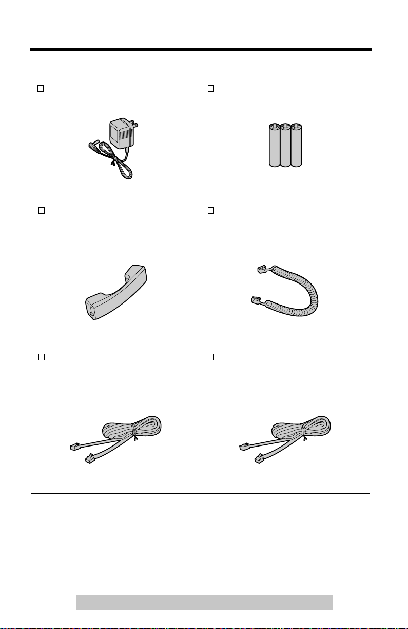
Accessories
AC Adaptor (p. 10)
Order No. KX-TCA1-G
(included)
For extra orders, call 1-800-332-5368.
AA (R6, UM-3) Batteries (p. 9)
one
Handset (p. 10)
Order No.
PQJXC0401Z (Black)
PQJXC0402Z (White)
one
4-Wire Telephone Line Cord
with Green Plugs
(p. 11-13)
Order No. PQJA10088Z
one
three
Handset Cord (p. 10)
Order No.
PQJA212V (Black)
PQJA212M (White)
one
2-Wire Telephone Line Cord
with Transparent Plugs (p. 13, 14)
Order No. PQJA10075Z
one
For assistance, please call: 1-800-211-PANA(7262)
3

Contents
Preparation
Location of Controls . . . . . . . . . . . . . . . . . . . . . . . . . . . . . . . . . . . . . . . . 6
Display . . . . . . . . . . . . . . . . . . . . . . . . . . . . . . . . . . . . . . . . . . . . . . . . . . . 8
Installation . . . . . . . . . . . . . . . . . . . . . . . . . . . . . . . . . . . . . . . . . . . . . . . . 9
Installing the Batteries . . . . . . . . . . . . . . . . . . . . . . . . . . . . . . . . . . . . . . . 9
Connecting the Handset and AC Adaptor . . . . . . . . . . . . . . . . . . . . . . . 10
Connecting Telephone Line Cords . . . . . . . . . . . . . . . . . . . . . . . . . . . . 11
Connecting a Communication Device . . . . . . . . . . . . . . . . . . . . . . . . . . 14
Programmable Settings. . . . . . . . . . . . . . . . . . . . . . . . . . . . . . . . . . . . . 15
Time and Date . . . . . . . . . . . . . . . . . . . . . . . . . . . . . . . . . . . . . . . . . . . . 15
Assigning the Extension Number. . . . . . . . . . . . . . . . . . . . . . . . . . . . . . 17
Programming Summary. . . . . . . . . . . . . . . . . . . . . . . . . . . . . . . . . . . . . 19
Dialing Mode . . . . . . . . . . . . . . . . . . . . . . . . . . . . . . . . . . . . . . . . . . . . . 20
LCD Contrast . . . . . . . . . . . . . . . . . . . . . . . . . . . . . . . . . . . . . . . . . . . . . 21
Ringer Volume . . . . . . . . . . . . . . . . . . . . . . . . . . . . . . . . . . . . . . . . . . . . 22
Ringer Pattern . . . . . . . . . . . . . . . . . . . . . . . . . . . . . . . . . . . . . . . . . . . . 23
Basic Operation
Making Calls . . . . . . . . . . . . . . . . . . . . . . . . . . . . . . . . . . . . . . . . . . . . . . 25
Answering Calls . . . . . . . . . . . . . . . . . . . . . . . . . . . . . . . . . . . . . . . . . . . 28
Caller ID Service. . . . . . . . . . . . . . . . . . . . . . . . . . . . . . . . . . . . . . . . . . . 29
Using the Caller List . . . . . . . . . . . . . . . . . . . . . . . . . . . . . . . . . . . . . . . 30
Viewing the Caller List . . . . . . . . . . . . . . . . . . . . . . . . . . . . . . . . . . . . . . 30
Calling Back from the Caller List . . . . . . . . . . . . . . . . . . . . . . . . . . . . . . 32
Editing the Caller’s Phone Number . . . . . . . . . . . . . . . . . . . . . . . . . . . . 33
The Caller ID Number Auto Edit Feature. . . . . . . . . . . . . . . . . . . . . . . . 34
Storing Caller List Information in the Directory or
in the One-Touch Dialer Memory. . . . . . . . . . . . . . . . . . . . . . . . . . . . . 36
Erasing Caller List Information. . . . . . . . . . . . . . . . . . . . . . . . . . . . . . . . 37
Advanced Operation
Directory . . . . . . . . . . . . . . . . . . . . . . . . . . . . . . . . . . . . . . . . . . . . . . . . . 38
Storing Names and Numbers. . . . . . . . . . . . . . . . . . . . . . . . . . . . . . . . . 38
Finding Stored Items . . . . . . . . . . . . . . . . . . . . . . . . . . . . . . . . . . . . . . . 40
Dialing . . . . . . . . . . . . . . . . . . . . . . . . . . . . . . . . . . . . . . . . . . . . . . . . . . 41
4

Editing. . . . . . . . . . . . . . . . . . . . . . . . . . . . . . . . . . . . . . . . . . . . . . . . . . .42
Erasing . . . . . . . . . . . . . . . . . . . . . . . . . . . . . . . . . . . . . . . . . . . . . . . . . .43
One-Touch Dialer . . . . . . . . . . . . . . . . . . . . . . . . . . . . . . . . . . . . . . . . . . 44
Storing Names and Numbers. . . . . . . . . . . . . . . . . . . . . . . . . . . . . . . . .44
Dialing a Stored Number . . . . . . . . . . . . . . . . . . . . . . . . . . . . . . . . . . . .45
Intercom . . . . . . . . . . . . . . . . . . . . . . . . . . . . . . . . . . . . . . . . . . . . . . . . .46
Paging a Designated Extension . . . . . . . . . . . . . . . . . . . . . . . . . . . . . . .46
Paging All Extensions. . . . . . . . . . . . . . . . . . . . . . . . . . . . . . . . . . . . . . . 48
Transferring an External Call to Another Extension . . . . . . . . . . . . . . . .48
Room Monitor Feature . . . . . . . . . . . . . . . . . . . . . . . . . . . . . . . . . . . . . .49
Making/Answering Another Call During a Conversation . . . . . . . . . . 50
Conference . . . . . . . . . . . . . . . . . . . . . . . . . . . . . . . . . . . . . . . . . . . . . . . 51
Special Features. . . . . . . . . . . . . . . . . . . . . . . . . . . . . . . . . . . . . . . . . . .52
How to Use the PAUSE Button (For PBX Line/Long Distance Calls). . .52
Muting Your Conversation . . . . . . . . . . . . . . . . . . . . . . . . . . . . . . . . . . .52
For Call Waiting Service Users. . . . . . . . . . . . . . . . . . . . . . . . . . . . . . . .52
Temporary Tone Dialing (For Rotary or Pulse Service Users). . . . . . . . 53
FLASH Button. . . . . . . . . . . . . . . . . . . . . . . . . . . . . . . . . . . . . . . . . . . . .53
Incoming Call Tone. . . . . . . . . . . . . . . . . . . . . . . . . . . . . . . . . . . . . . . . .54
Line Selection. . . . . . . . . . . . . . . . . . . . . . . . . . . . . . . . . . . . . . . . . . . . .55
Setting the Password . . . . . . . . . . . . . . . . . . . . . . . . . . . . . . . . . . . . . . .56
Dial Lock. . . . . . . . . . . . . . . . . . . . . . . . . . . . . . . . . . . . . . . . . . . . . . . . .57
Call Restriction . . . . . . . . . . . . . . . . . . . . . . . . . . . . . . . . . . . . . . . . . . . .58
Call Privacy Feature. . . . . . . . . . . . . . . . . . . . . . . . . . . . . . . . . . . . . . . .60
Useful Information
Optional Headset . . . . . . . . . . . . . . . . . . . . . . . . . . . . . . . . . . . . . . . . . .61
Connecting the Optional Headset to the Unit. . . . . . . . . . . . . . . . . . . . .61
Wall Mounting. . . . . . . . . . . . . . . . . . . . . . . . . . . . . . . . . . . . . . . . . . . . .62
Troubleshooting . . . . . . . . . . . . . . . . . . . . . . . . . . . . . . . . . . . . . . . . . . .64
Important Safety Instructions . . . . . . . . . . . . . . . . . . . . . . . . . . . . . . . . 67
Basic Operation Useful InformationAdvanced OperationPreparation
FCC and Other Information . . . . . . . . . . . . . . . . . . . . . . . . . . . . . . . . . .69
Index . . . . . . . . . . . . . . . . . . . . . . . . . . . . . . . . . . . . . . . . . . . . . . . . . . . .71
Warranty . . . . . . . . . . . . . . . . . . . . . . . . . . . . . . . . . . . . . . . . . . . . . . . . .73
Specifications . . . . . . . . . . . . . . . . . . . . . . . . . . . . . . . . . . . . . . . . . . . . .75
For assistance, please call: 1-800-211-PANA(7262)
5
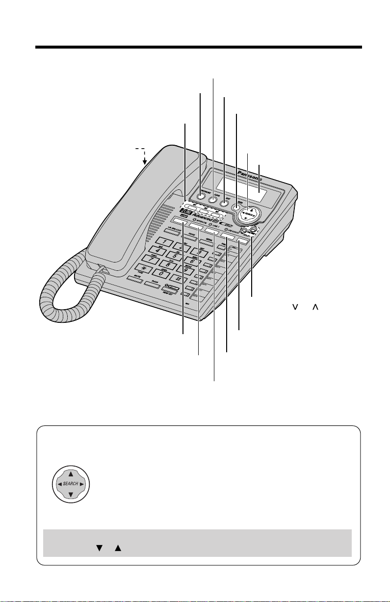
Location of Controls
[FUNCTION/EDIT] Button
(p. 19, 33)
One-Touch Auto Dial Buttons
[M1], [M2], [M3] (p. 44)
Headset Jack (p. 61)
[CLEAR] Button (p. 37, 43)
[EXIT] Button (p. 19, 30, 40)
[ENTER] Button (p. 15, 17)
Navigator Key
([▼], [▲], [ ], [ ])
(p. 15, 19, 30, 40)
Display (p. 8)
VOLUME [ ], [ ] Buttons
(p. 26)
▼
▼
[CONF] (Conference) Button (p. 51)
[INTERCOM] Button and
Indicator (p. 46, 47)
[LINE 1] Button and Indicator (p. 25, 27)
How to use the Navigator key
This key has four active areas that are indicated by arrows.
• Pressing the up and down arrows allows you to enter the
Caller List and scroll through the Caller List, the directory list
and the function menu.
• Pressing the right and left arrows allows you to enter the
directory list and move the cursor when entering items.
• The right arrow is used to select your menu choices.
Throughout these Operating Instructions, the navigator key is indicated by
the arrows [], [], [] or [].
▼
▼
[HOLD] Button (p. 27, 48)
[LINE 2/DATA] Button and
Indicator (p. 25, 27)
6
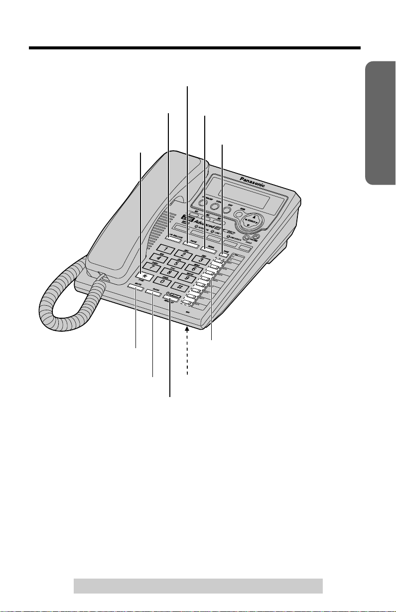
[PAUSE] Button (p. 52)
[PAUSE] Button (p. 52)
Preparation
[DIAL LOCK] Button (p. 57)
[DIAL LOCK] Button (p. 57)
[R] (TONE) Button (p. 53)
[R] (TONE) Button (p. 53)
[MUTE] Button (p. 52)
[MUTE] Button (p. 52)
[FLASH] Button (p. 53)
[FLASH] Button (p. 53)
[REDIAL] Button (p. 26)
[REDIAL] Button (p. 26)
[PAGE] Button (p. 48)
[PAGE] Button (p. 48)
Extension Buttons and Indicators
Extension Buttons and Indicators
(p. 18, 46)
(p. 18, 46)
MIC (Microphone) (p. 25, 28)
MIC (Microphone) (p. 25, 28)
[SP-PHONE (Speakerphone)/HEADSET]
[SP-PHONE (Speakerphone)/HEADSET]
Button and Indicator (p. 25, 28, 61)
Button and Indicator (p. 25, 28, 61)
For assistance, please call: 1-800-211-PANA(7262)
7
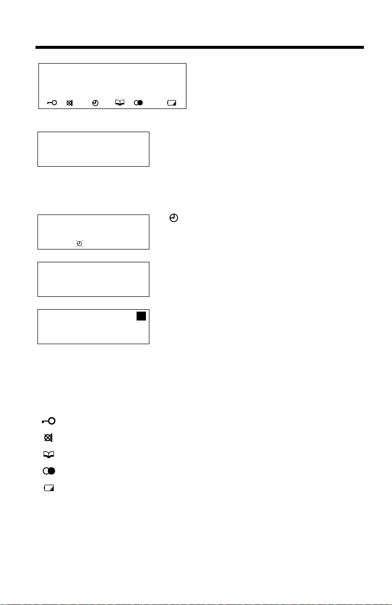
Display
1234567890123456
ABCDEFGHIJKLMNOP
(This display shows all of the possible
configurations.)
abcdefghijklmnop
12:34AM 5/21[1]
10 new calls
12:00 1.1 [1]
12:34AM 5/21[1]
01-06-35
SMITH,JACK
1-222-333-4444
11:20AM 1/10 x3
When the handset is on the cradle, the AC
adaptor is connected and the SP-PHONE/
HEADSET indicator light is off, the display
shows the current time and date, the extension
number, and the number of new calls if you
subscribed to a Caller ID service (p. 29).
If “” flashes on the display, the clock needs
adjusting (p. 15, 16).
During a conversation, the display shows the
length of the call (ex. 1 hour, 6 minutes and
35 seconds).
This is a display from the Caller List. The
1
display shows:
— the caller’s name,
— the called line,
— the caller’s number,
— the time and date of the last call
(ex. Jan. 10, 11:20 AM), and
— the number of times called (ex. 3 times).
: The dial lock mode is set (p. 57).
: [MUTE] was pressed during a conversation (p. 52).
: Displays when storing or viewing the directory items (p. 38, 40).
: Displays while viewing the redial list (p. 26).
: The battery power is low or the batteries have not been installed.
To replace or install the batteries, see page 9.
P
: [PAUSE] was pressed while dialing or storing phone numbers.
F
: [FLASH] was pressed while storing phone numbers.
8
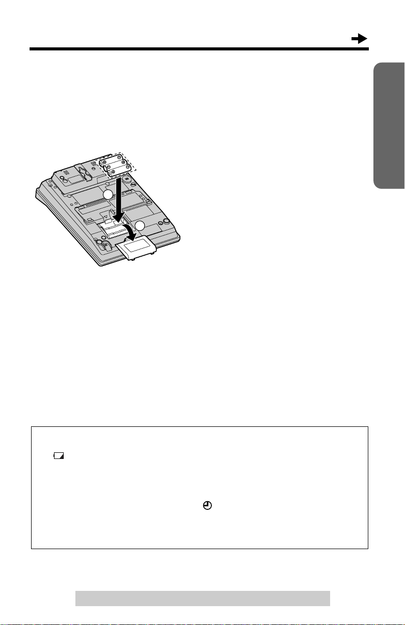
Installation
Installing the Batteries
Install the three included batteries in the battery compartment. They work
as emergency power during a power failure. The unit will work as a
standard telephone, so that you can make or ans w er e xternal calls with the
handset. (You cannot use the intercom.)
1. Press down the cover in the
direction of the arrow and remove
2
1
• Please refer to page 68 for correct battery usage.
• You can also install three “AA” size Alkaline (LR6) batteries.
• The battery operating time may depend on usage conditions and ambient
temperature.
• The battery operating time during a power failure is about three weeks for the
three included “AA” size Manganese (R6, UM-3) batteries. The battery operating
time will be longer for three “AA” size Alkaline (LR6) batteries.
• During a power failure the batteries will retain the clock memory (p. 15) and the
redial memory (p. 26). If you do not install the batteries, the data in memory will be
lost during a power failure.
it.
2. Install the batteries in proper order
as shown, matching the correct
polarity.
3. Close the battery cover.
Preparation
Battery replacement
If “” flashes, the battery power is low. Replace all of the batteries with
new ones.
Disconnect the telephone line cord(s) before opening the battery cover.
• You do not need to disconnect the AC adaptor, otherwise the clock memory
and the redial memory will be lost. If “” flashes on the display, adjust the
clock (p. 15, 16).
• Please refer to page 68 for correct battery usage.
For assistance, please call: 1-800-211-PANA(7262)
9
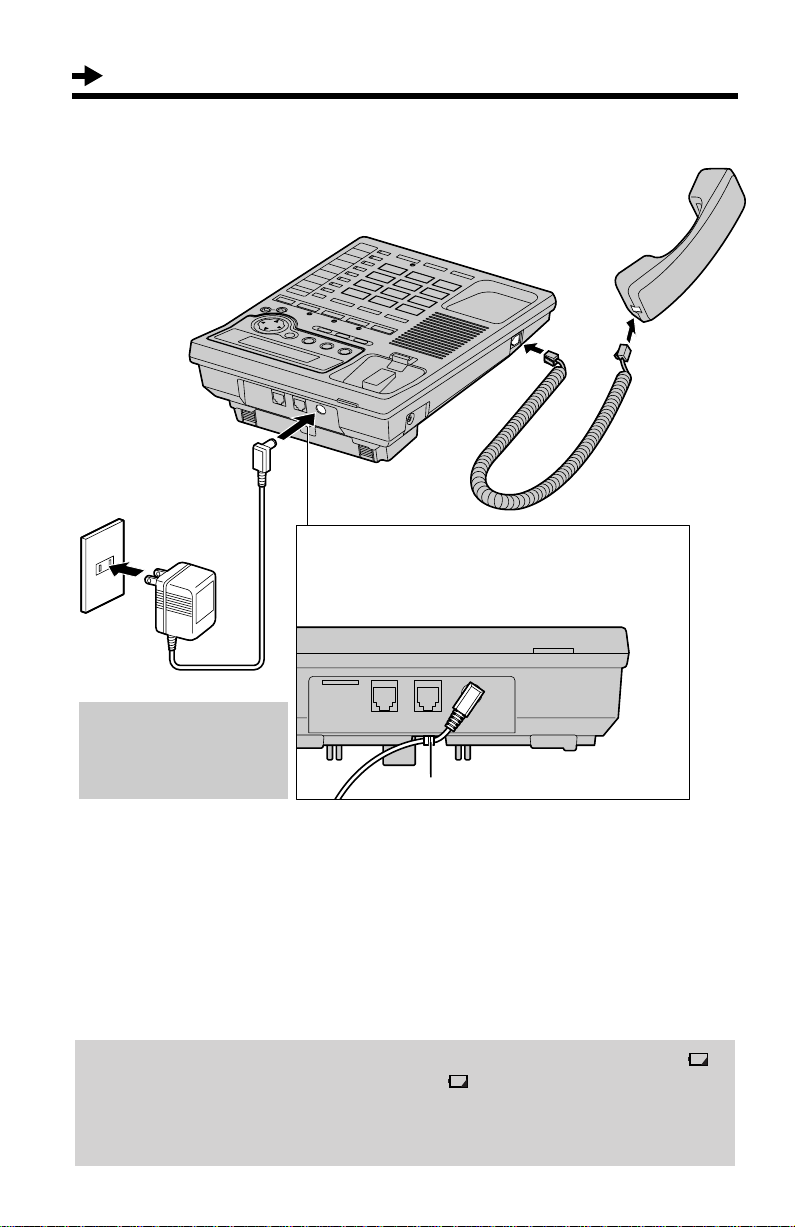
Installation
Connecting the Handset and AC Adaptor
Handset
Handset
Handset Cord
Power Outlet
(AC 120 V, 60 Hz)
Handset Cord
Power Outlet
(AC 120V, 60Hz)
AC Adaptor
After completing all the
connections (p. 10-14),
plug the AC adaptor into
the power outlet.
• USE ONLY WITH Panasonic AC ADAPTOR KX-TCA1 (Order No. KX-TCA1-G).
• Use only a Panasonic Handset for the KX-TS3282B/KX-TS3282W.
• The AC adaptor must remain connected at all times. (It is normal for the adaptor to
feel warm during use.)
• After you connect the AC adaptor;
AC Adaptor
Remove the wall mounting adaptor (see page
62, step 2), then fasten the AC adaptor cord to
prevent it from being disconnected. Attach the
wall mounting adaptor again.
LINE2/DATA LINE1/2
Hook
—the display shows “Set clock” (p. 15) for 60 seconds, and
—all of the extension indicators flash until you assign the extension number of
your unit (p. 17). Even if you do not use the intercom, assign the number.
Otherwise all of the extension indicators will continue flashing.
If you plug the AC adaptor into the pow er outlet without installing batteries, “”
flashes. After you install the batteries (p. 9),
During a power failure, the batteries serve as the power source (p. 9). The unit
will work as a standard telephone. You can make or answer an external call with
the handset. (You cannot use the intercom.)
“” disappears.
10
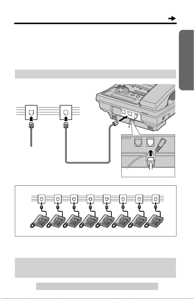
Connecting T elephone Line Cor ds
A maximum of eight KX-TS3282Bs/KX-TS3282Ws can be connected in
parallel. You can also connect KX-T3281W.
To use the intercom, you must connect the telephone line cord to the
LINE1/2 telephone jack of the unit.
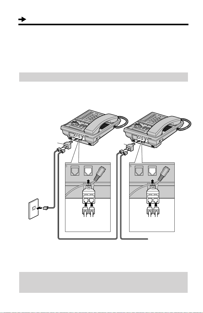
To connect the units to individual two-line telephone jacks
Parallel Connected
Two-Line Telephone Jacks (RJ14C)
Preparation
To another unit
4-Wire T elephone Line
Cord with GREEN Plugs
LINE2/DATA LINE1/2
GREEN Plug
Parallel connected two-line telephone jacks
• You can connect up to 8 stations.
• If another model telephone is connected to the KX-TS3282B/KX-TS3282W except
for KX-T3281W, the line indicators of this unit will not function for that telephone.
DSL Internet connection and KX-TS3282B/KX-TS3282W Intercom work at
similar frequencies. Please contact Panasonic at 1-800-211-PANA(7262) for
special wiring configurations.
For assistance, please call: 1-800-211-PANA(7262)
11
Installation
• If you re-connect the telephone line cord(s), confirm that all of the extension
indicators light with the AC adaptor connected, then connect the telephone line
cord(s). If all of the extension indicators do not flash, the extension number has
been assigned to this unit and the number might be used for another unit on the
same line. Erase the previously assigned number (p. 17), then connect the
telephone line cord(s). Re-assign the number to the unit (p. 17).
To connect the units to a two-line telephone jack
If you provide only one two-line telephone jack for the units, continue to
wire them using optional Panasonic T-adaptors KX-J66. To order, call the
accessories telephone number on page 3.
T-Adaptor
(KX-J66)
4-Wire T elephone
Line Cord with
GREEN Plugs
LINE 1
LINE 2
Two-Line
Telephone Jack
(RJ14C)
DSL Internet connection and KX-TS3282B/KX-TS3282W Intercom work at
similar frequencies. Please contact Panasonic at 1-800-211-PANA(7262) for
special wiring configurations.
LINE2/DATA LINE1/2 LINE2/DATA LINE1/2
GREEN
Plug
4-Wire Telephone Line Cord
with GREEN Plugs
GREEN
Plug
T-Adaptor
(KX-J66)
GREEN
Plug
4-Wire T elephone
Line Cord with
GREEN Plugs
GREEN
Plug
To another unit
12
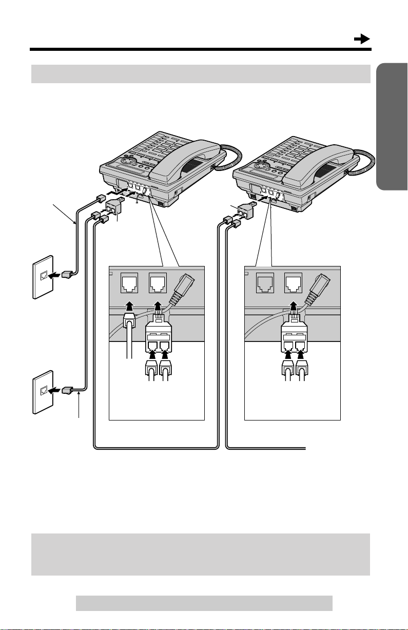
To connect the units to two single-line telephone jacks
If you provide only two single-line telephone jacks for the units, continue to
wire them using optional Panasonic T-adaptors KX-J66. To order, call the
accessories telephone number on page 3.
4-Wire T elephone
Line Cord with
GREEN Plugs
T-Adaptor
(KX-J66)
LINE 2
LINE2/DATA LINE1/2 LINE2/DATA LINE1/2
Single-Line
Telephone
Jacks (RJ11C)
T-Adaptor
(KX-J66)
Preparation
LINE 1
2-Wire T elephone
Line Cord with
TRANSPARENT
Plugs
• If you do not connect other extensions, you do not need to use a T-adaptor.
Connect a 2-wire telephone line cord to the LINE1/2 telephone jack of the unit
directly.
DSL Internet connection and KX-TS3282B/KX-TS3282W Intercom work at
similar frequencies. Please contact Panasonic at 1-800-211-PANA(7262) for
special wiring configurations.
GREEN
Plug
TRANSPARENT
Plug
4-Wire Telephone Line Cord
with GREEN Plugs
For assistance, please call: 1-800-211-PANA(7262)
GREEN
Plug
GREEN
Plug
4-Wire T elephone
Line Cord with
GREEN Plugs
GREEN
Plug
To another
unit
13
Installation
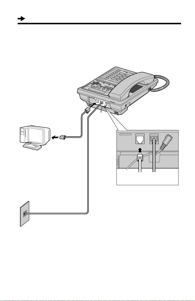
Connecting a Communication Device
After connecting the telephone line cord to a two-line telephone jack, you
can connect a communication device (computer, modem, fax, answering
machine, etc.) through this unit using the LINE2/DATA jack.
• Computer
• Modem
• Fax
• Answering Machine
2-Wire Telephone
Line Cord with
TRANSPARENT
Plugs
TRANSPARENT
Plug
4-Wire Telephone
Line Cord with
GREEN Plugs
Two-Line
Telephone Jack
(RJ14C)
• If the communication device is in use, use LINE 1 to make or answer other calls.
Otherwise the communication device may not operate properly.
LINE2/DATA LINE1/2
GREEN
Plug
14
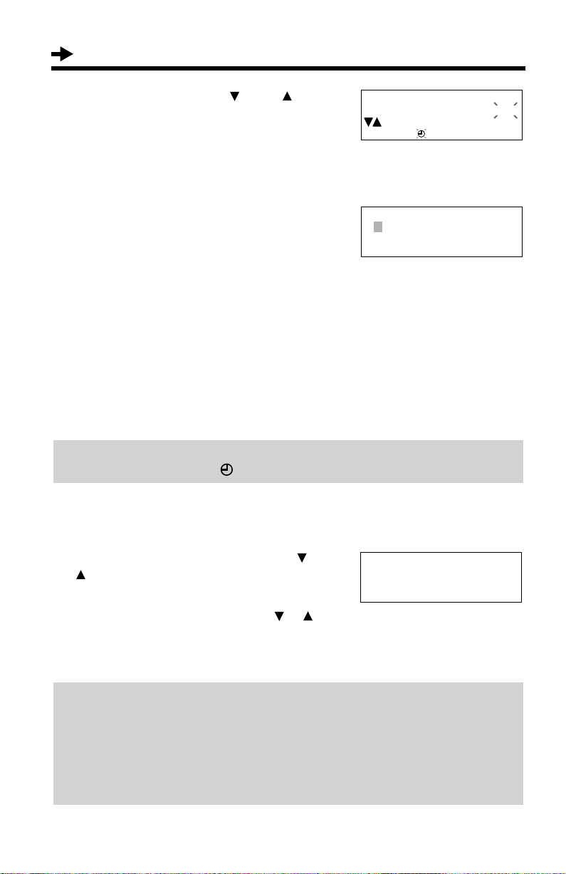
Set clock
ENTER=Yes
▼
12:00AM 01/01
2002
ENTER=Save
▼
▼
09:30AM 01/01
2002
ENTER=Save
▼
▼
Ex. Time: 09:30
09:30PM 01/01
2002
ENTER=Save
▼
▼
09:30PM 12/27
2002
ENTER=Save
▼
▼
Ex. Dec. 27
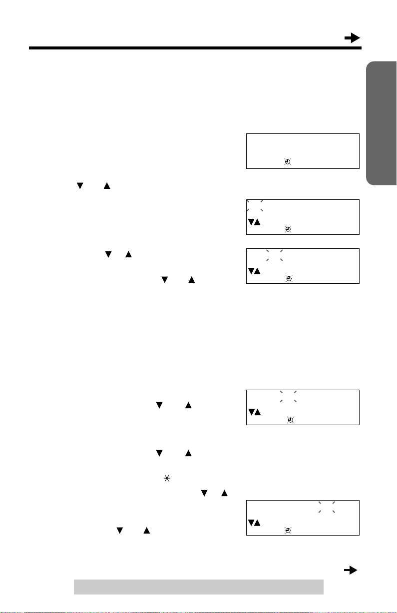
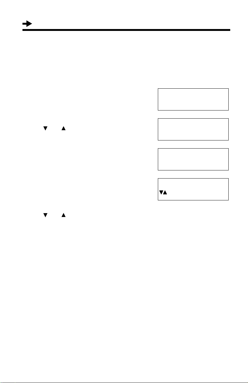
Programmable Settings
Time and Date
You can select 12-hour clock (AM/PM) or 24-hour clock by programming.
Make sure that the handset is on the cradle, the A C adaptor is connected
and the SP-PHONE/HEADSET indicator light is off.
After the AC adaptor is connected, the display
will show “Set clock” for 60 seconds.
• If the display exits the set clock menu, press
[FUNCTION/EDIT], then scroll to “Set clock” by
pressing [] or [].
Preparation
Press [] or [ENTER] (Yes key).
1
(1) Enter the time (hour and minute)
2
using [], [] and [].
• You can scroll to the desired hour/
minute by pressing [] or [].
To move forward, press []. To move
backward, press [].
• For 12-hour clock, enter “0100” to “1259”.
For 24-hour clock, enter “0000” to “2359”.
•
If you entered “00” or between “13” and “23”
for the hour, enter the minute and press
[], then go to step 3
▼
• You can also enter the time using the
dialing buttons ([0] to [9]).
(2) For 12-hour clock, select “AM” or
“PM” by pressing [] or [], and
press [].
For 24-hour clock, if the hour is
between 1 and 12, erase “AM” or
-
3
“PM” by pressing [] or [], and press [].
• You can also select “AM” or “PM” or
erase it by pressing [].
Enter the month and day using [], []
and [].
▼
• You can scroll to the desired month/day
by pressing [] or []. To move forward,
press []. To move backward, press [].
• You can also enter the month/day using the dialing buttons ([0] to [9]).
For assistance, please call: 1-800-211-PANA(7262)
▼
▼
▼
▼
▼
▼
.
▼
▼
(Continued )
15
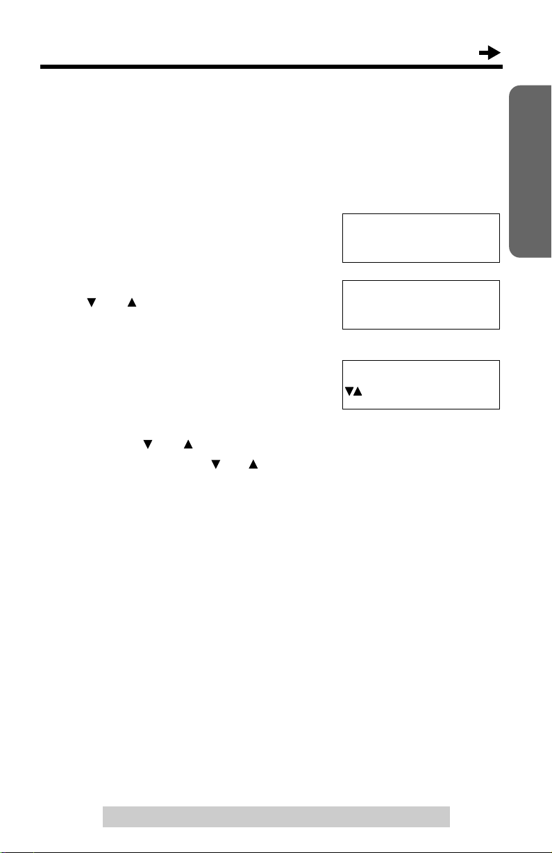
Programmable Settings
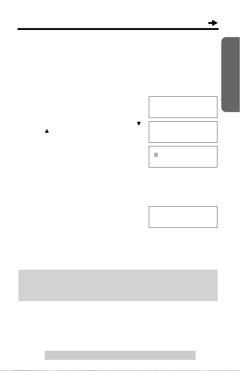
09:30PM 12/27
2002
ENTER=Save
▼
▼
Extension#
12345678 Erase
ENTER=Save
▼
▼
Caller ID edit
Set clock
Assign EXT#
▼
Enter the year using [] and [].
4
• You can select the year between 2000
and 2099.
• You can also select the year entering the
last 2-digits using the dialing buttons ([0]
to [9]).
Press [ENTER] (Save key).
5
• A beep sounds.
• The clock starts working.
• If 3 beeps are heard, the setting is not
correct. Start again from step 2.
• The display will go to the extension
number assigning menu as shown on the
right if you had started programming
within 60 seconds after plugging in the
AC adaptor. The menu will remain for 60
seconds. To assign a number, see page
17, from step 4.
• You can exit the programming mode any time by pressing [EXIT].
If a power failure occurs, the adjusted time/date will be retained by installing the
batteries (p. 9). Readjust if “” flashing on the display.
To adjust the time and date
1. Press [FUNCTION/EDIT].
2. Scroll to “Set clock” by pressing [] or
[], and press [].
3. Adjust the time and date, using [], [], []
or [].
▼
4. Press [ENTER] (Save key).
For Caller ID service users (p. 29)
• The Caller ID information will reset the clock after the first ring if the adjusted
time is incorrect.
• If the clock has not previously been set, the Caller ID information will not adjust
the clock.
• The Caller ID information will automatically adjust the clock for daylight saving
time.
16
▼
▼
Assigning the Extension Number
–––––––––––––––
Save M1,M2,M3
Save directory
▼
Set clock
Assign EXT#
–––––––––––––––
▼
Extension#
12345678 Erase
ENTER=Save
▼
▼
Extension#
1
Ex. Extension number 1
Assign the extension number to the unit to use the intercom feature.
Make sure that the unit has been connected to other units (KX-TS3282B,
KX-TS3282W and/or KX-T3281W) in parallel (p. 11-13) before programming.
Make sure that the handset is on the cradle, the AC adaptor is
connected and the SP-PHONE/HEADSET indicator light is off.
Press [FUNCTION/EDIT].
1
Scroll to “Assign EXT#” by pressing []
2
or [].
Preparation
Press [].
3
• The numbers (1 to 8) that have already
been assigned to other units are not
displayed.
Press [] or [] to move the cursor to
4
select the extension number (1 to 8).
Press [ENTER] (Save key).
5
• A beep sounds.
• The extension number ([1] to [8]) is shown on the
right.
• You can exit the programming mode any time by pressing [EXIT].
• To change the extension number, start from step 1. The previous memory will be
erased.
• To exchange the extension numbers between two units, erase each number (see
below), then re-assign the number to each unit.
After you connect the AC adaptor (p. 10), all of the extension indicators flash
until you assign the extension number of your unit. Even if you do not use the
intercom, assign the number. Otherwise all of the extension indicators will
continue flashing.
To erase the extension number
Repeat steps 1 to 3, and select “Erase” by pressing []. Press [ENTER]
(Save key).
•“Extension# Not assign” is displayed.
• All extension indicators flash until you assign a number to the unit.
For assistance, please call: 1-800-211-PANA(7262)
▼▼
▼
17
Programmable Settings
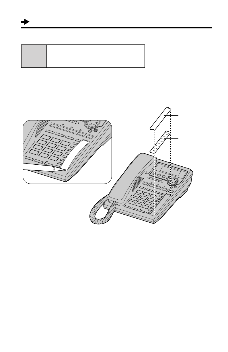
What the extension indicators mean
Off The extension is not in use.
On The extension is in use.
Memory card
Remove the memory card and use it as a name index for extensions.
Cover
Memory Card
18
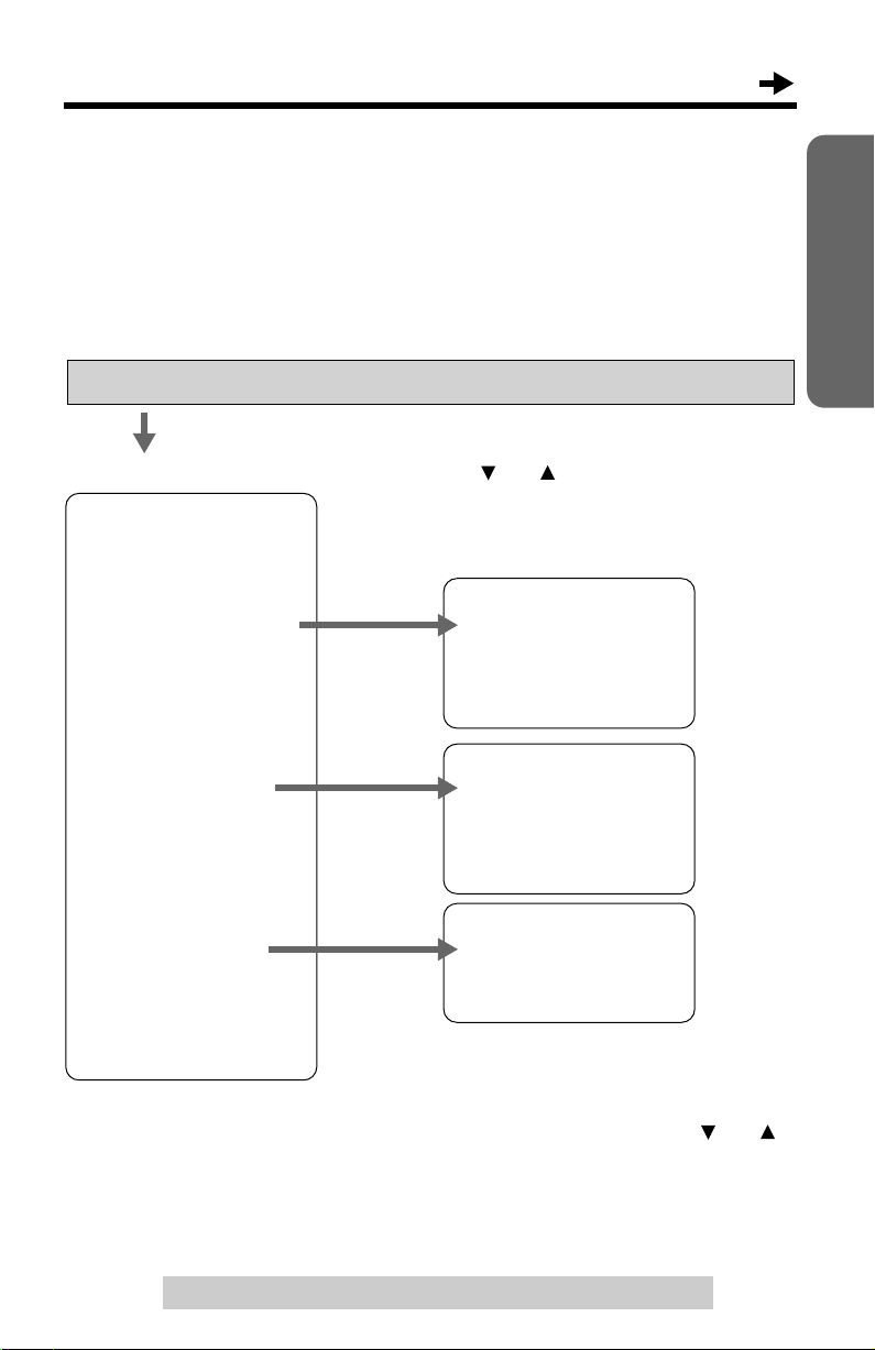
Programming Summary
▼▼▼▼▼
You can program the following functions from the menu. After pressing
[FUNCTION/EDIT], the main menu will be displayed first. If the main menu
item has the sub-menu, it will be displayed. See the corresponding pages
for function details.
Make sure that the handset is on the cradle, the A C adaptor is connected
and the SP-PHONE/HEADSET indicator light is off.
Press [FUNCTION/EDIT].
• Scroll to a desired item by pressing
<Main menu>
–––––––––––––––
Save M1,M2,M3 . . . . . p. 44
Save directory . . . . p. 38
LCD contrast . . . . . . p. 21
Ringer setting
[] or [], and press
<Sub menu>
–––––––––––––––
Ringer volume . . . . . p. 22
Ringer pattern . . . . p. 23
Incoming call . . . . . p. 54
–––––––––––––––
[].
Preparation
Change password . . . p. 56
Dial setting
–––––––––––––––
Set dial mode . . . . . p. 20
Set flash time . . . . p. 53
Call restrict . . . . . p. 58
–––––––––––––––
–––––––––––––––
Line setting
Caller ID edit . . . . p. 35
Set clock. . . . . . . . . . p. 15
Line selection . . . . p. 55
Call barge in . . . . . p. 60
–––––––––––––––
Assign EXT# . . . . . . . p. 17
–––––––––––––––
During programming
• To select a desired function item, scroll through the menu by pressing [] or [].
Then press
•“
–––––––––––––––” indicates the beginning or end of the function menu.
• You can exit the programming mode any time by pressing [EXIT].
• If you do not press any buttons for 60 seconds, the unit will exit the programming
mode.
[] to go to the next step.
▼
For assistance, please call: 1-800-211-PANA(7262)
19
Programmable Settings
–––––––––––––––
Save M1,M2,M3
Save directory
▼
Change password
Dial setting
Line setting
▼
–––––––––––––––
Set dial mode
Set flash time
▼
Dial mode
:Tone
ENTER=Save
Dialing Mode
If you have touch tone service, set to Tone. If rotary or pulse service is
used, set to Pulse. Your phone comes from the factory set to Tone.
Make sure that the handset is on the cradle, the A C adaptor is connected
and the SP-PHONE/HEADSET indicator light is off.
Press [FUNCTION/EDIT].
1
Scroll to “Dial setting” by pressing
2
[] or [].
Press [].
3
Press [] at “Set dial mode”.
4
• The current setting is displayed.
Select “Pulse” or “Tone” by pressing
5
[] or [].
Press [ENTER] (Save key).
6
• A beep sounds.
• To exit the programming mode, press
[EXIT].
• You can exit the programming mode any time by pressing [EXIT].
▼
▼
20
LCD Contrast
–––––––––––––––
Save M1,M2,M3
Save directory
▼
Save directory
LCD contrast
Ringer setting
▼
LCD contrast
Low
■ ■ ■ ■ ■ ■
High
ENTER=Save
Ex. Level 3
You can select the LCD contrast level from 1 to 4 by prog ramming. To make
the display clearer , set to high level. Your phone comes from the factory set
to 3.
Make sure that the handset is on the cradle, the A C adaptor is connected
and the SP-PHONE/HEADSET indicator light is off.
Press [FUNCTION/EDIT].
1
Scroll to “LCD contrast” by pressing
2
[] or [].
Preparation
Press [].
3
• The current setting is displayed.
•“
Select the desired LCD contrast by
4
pressing [] or [].
• Each time you press [] or [], the LCD
contrast will change.
Press [ENTER] (Save key).
5
• A beep sounds.
• To exit the programming mode, press
[EXIT].
• You can exit the programming mode any time by pressing [EXIT].
▼
■ ■
” shows one level.
For assistance, please call: 1-800-211-PANA(7262)
21

Programmable Settings
–––––––––––––––
Save M1,M2,M3
Save directory
▼
LCD contrast
Ringer setting
Change password
▼
–––––––––––––––
Ringer volume
Ringer pattern
▼
Ringer V olume
You can select the ringer volume for each external line and the intercom
line individually. Set to HIGH, LOW, or OFF. If set to OFF for Line 1 and/or
Line 2, the unit will not ring for the line(s). If the ringer for the intercom line
is OFF, the unit will not ring for intercom calls. Your phone comes from the
factory set to HIGH.
Make sure that the handset is on the cradle, the A C adaptor is connected
and the SP-PHONE/HEADSET indicator light is off.
Press [FUNCTION/EDIT].
1
Scroll to “Ringer setting” by
2
pressing [] or [].
Press [].
3
Press [] at “Ringer volume”.
4
Select each ringer volume:
5
(1) Select “L1”, “L2” or
“Intercom” by pressing [] or
▼
[].
(2) Select the desired volume by
pressing [] or [].
• Each time you press [] or [],
the volume will change and ring.
• To turn the ringer OFF, press
[] repeatedly until “Ringer
off” is displayed.
Press [ENTER] (Save key).
6
• A beep sounds.
• To exit the programming mode, press
[EXIT].
To turn the ringer ON:
Repeat steps 1 to 4, and select “L1”, “L2” or “Intercom”.
Press [], and press [ENTER] (Save key).
• The ringer will sound at the LOW level for the line.
22
▼▼
Ex. Line 1 is selected.
Ringer volume
HIGH
▼
L1 L2 Intercom
Low
■ ■ ■ ■ ■ ■
High
Ringer volume
L1 L2 Intercom
LOW
Low
OFF
L1 L2 Intercom
■ ■ ■
High
Ringer volume
Ringer off
• You can exit the programming mode any time by pressing [EXIT].
1
• If set to OFF, “Ringer off” with the line(s) (“”, “” and/or “INT”) is(are)
displayed while the unit is not in use (standby mode).
• You can also change each ringer volume while the unit is just ringing for the
external/intercom line, by pressing VOLUME [] or []. To turn the ringer OFF,
press and hold VOLUME [].
• You can change the ringer tone for Line 1, Line 2 and Intercom individually
(see below).
<
2
>
<
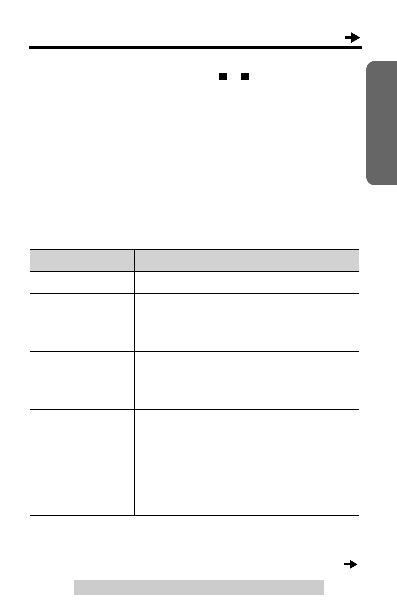
Ringer Pattern
You can select one of eight ringer tones for Line 1, Line 2 and Intercom
individually. For Intercom you can select another ringer pattern (Voice
mode, Auto Answer mode or Room Monitor mode), instead of the ringer
tone.
Line 1 is preset to “1”, Line 2 is preset to “2” and Intercom is preset to “3”.
Preparation
Ringer pattern
Ringer tone (1 to 8) The unit rings with the selected ringer tone.
Voice mode
(for Intercom only)
Auto Answer mode
(for Intercom only)
Room Monitor mode
(for Intercom only)
• When a paging extension pages all extensions, this ringer pattern setting is not
applicable (p. 48).
How the unit works when a call is being received.
T w o short beeps sound, then you are paged with
the caller’s voice instead of the bell. To answer
the page, press [SP-PHONE/HEADSET] or lift
the handset.
Two short beeps sound, then the speakerphone
turns on automatically, in response to the page.
Without pressing any button, 2-wa y intercom with
the paging party is established automatically.
Selecting the Room Monitor mode allows
another extension user to monitor through your
unit. Another extension can call your unit to
monitor a room through it (p. 49). Your unit will
not ring and the SP-PHONE/HEADSET
indicator will light. If you want to prevent your
unit from being monitored by other extensions,
do not select this mode.
(Continued )
For assistance, please call: 1-800-211-PANA(7262)
23
 Loading...