

Page 1
4-Channel VoIP Gateway Card
Getting Started
KX-TDA5480
Model KX-TDA0484
Thank you for purchasing the Panasonic 4-Channel VoIP Gateway Card, KX-TDA5480/KX-TDA0484.
Please read this manual carefully before using this product and save this manual for future use.
Page 2

Table of Contents
1 Overview........................................................................................... 5
1.1 Example Network Diagram ..................................................................................... 6
1.2 Network Devices and Numbering Plan.................................................................. 7
1.2.1 Network Application................................................................................................... 8
1.2.2 Numbering Plan Example.......................................................................................... 8
1.2.3 Numbering Plan Summary ...................................................................................... 12
2 Installing in the KX-TDA50 PBX ...................................................13
2.1 Installation.............................................................................................................. 14
2.1.1 Names and Locations.............................................................................................. 14
2.1.2 Installing the VoIP Gateway Card in the PBX .......................................................... 15
2.2 Cable Connection .................................................................................................. 17
2.2.1 Connection for Programming................................................................................... 17
2.2.2 Connection to the LAN ............................................................................................ 18
3 Installing in the KX-TDA100/KX-TDA200 PBX.............................19
3.1 Installation.............................................................................................................. 20
3.1.1 Names and Locations.............................................................................................. 20
3.1.2 Installing the VoIP Gateway Card in the PBX .......................................................... 21
3.2 Cable Connection .................................................................................................. 23
3.2.1 Connection for Programming................................................................................... 23
3.2.2 Connection to the LAN ............................................................................................ 24
4 Programming the VoIP Gateway Card .........................................25
4.1 Preparations........................................................................................................... 26
4.1.1 Preparing the PC ..................................................................................................... 26
4.2 Programming the VoIP Gateway Card in the Los Angeles Office ..................... 29
4.2.1 Starting the IP-GW4 Maintenance Utility................................................................. 29
4.2.2 Changing the Status of the VoIP Gateway Card...................................................... 31
4.2.3 Assigning the IP Address ........................................................................................ 32
4.2.4 Assigning the Hunt Pattern ...................................................................................... 33
4.2.5 Programming the Address Translation Table ........................................................... 34
4.2.6 Downloading the Address Translation Table from the VoIP Gateway Card ............. 37
4.2.7 Rebooting the VoIP Gateway Card .......................................................................... 38
4.2.8 Confirming the IP Address Assignment................................................................... 39
4.3 Programming the VoIP Gateway Card in the Chicago Office ............................ 40
5 Programming the PBX ..................................................................45
5.1 Programming the PBX in the Los Angeles Office .............................................. 46
5.2 Programming the PBX in the Chicago Office...................................................... 48
A Guidance for VoIP Installation......................................................51
A1 VoIP Requirements ................................................................................................ 52
A1.1 Bandwidth Assessment ........................................................................................... 52
A1.2 Network Configuration ............................................................................................. 53
A1.3 Network Devices...................................................................................................... 57
A1.4 QoS (Quality of Service).......................................................................................... 58
2 Getting Started
Page 3

A2 VoIP Requirements Checklist................................................................................59
B Alternative Numbering Plan Example .........................................61
B1 Extension Number Method....................................................................................62
B1.1 Example Network .....................................................................................................62
B1.2 Numbering Plan Example ........................................................................................63
B2 Programming for the Extension Number Method ...............................................65
B2.1 Programming the VoIP Gateway Card .....................................................................65
B2.2 Programming the PBX .............................................................................................66
C Initialization of the VoIP Gateway Card ....................................... 69
C1 Initializing the VoIP Gateway Card........................................................................70
D Using the KX-TDA5480/KX-TDA0484 and KX-TDA0480 in One
Network ..........................................................................................73
D1 Considerations in Installation...............................................................................74
Getting Started 3
Page 4

4 Getting Started
Page 5

Section 1
Overview
Panasonic PBX with VoIP Gateway Card will allow
organizations to route both voice and fax
communications over digital data networks.
The VoIP Gateway Card, designed to be easily
integrated into existing IP networks, seamlessly bridges
Public Switched Telephone Network (PSTN) and
analog telephones with digital data networks without
interrupting pre-existing data communications.
Because communications do not take place over
conventional telephone networks, the high cost of long
distance communications is virtually eliminated.
Getting Started 5
Page 6
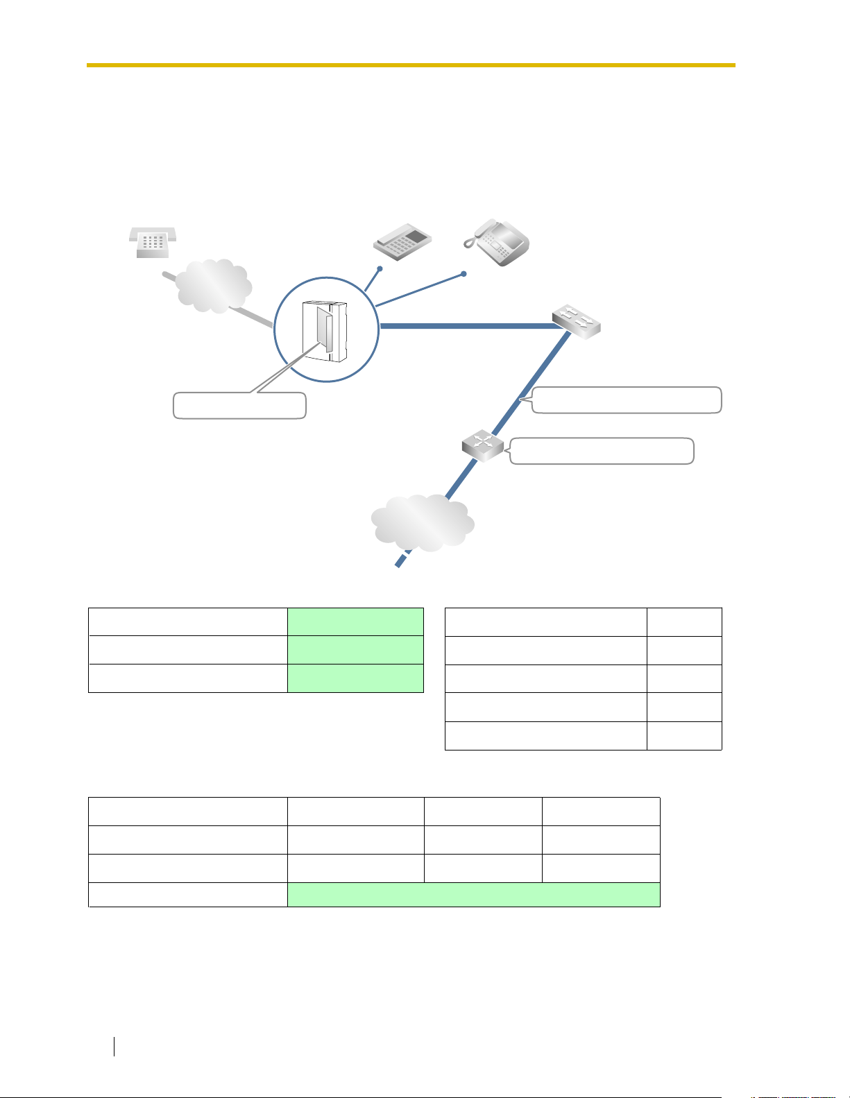
1.1 Example Network Diagram
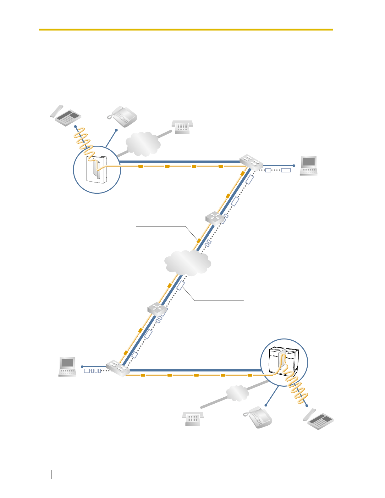
1.1 Example Network Diagram
The following diagram illustrates a simple VoIP network connecting PBXs at two locations. The
VoIP Gateway Card converts outgoing voice or fax signals into IP packets for transmission. On
the incoming side, it reverses this process and translates the packets back into appropriate
voice or fax signals.
PSTN
(Public Switched
Telephone Network)
Voice signals are converted
into IP packets.
KX-TDA50 PBX
with KX-TDA5480 VoIP Gateway Card
Voice data packets
Switching Hub
Router
IP Network
Other data packets
KX-TDA100/KX-TDA200 PBX
with KX-TDA0484 VoIP Gateway Card
IP packets are converted
back into voice signals.
PSTN
6 Getting Started
Page 7
1.2 Network Devices and Numbering Plan
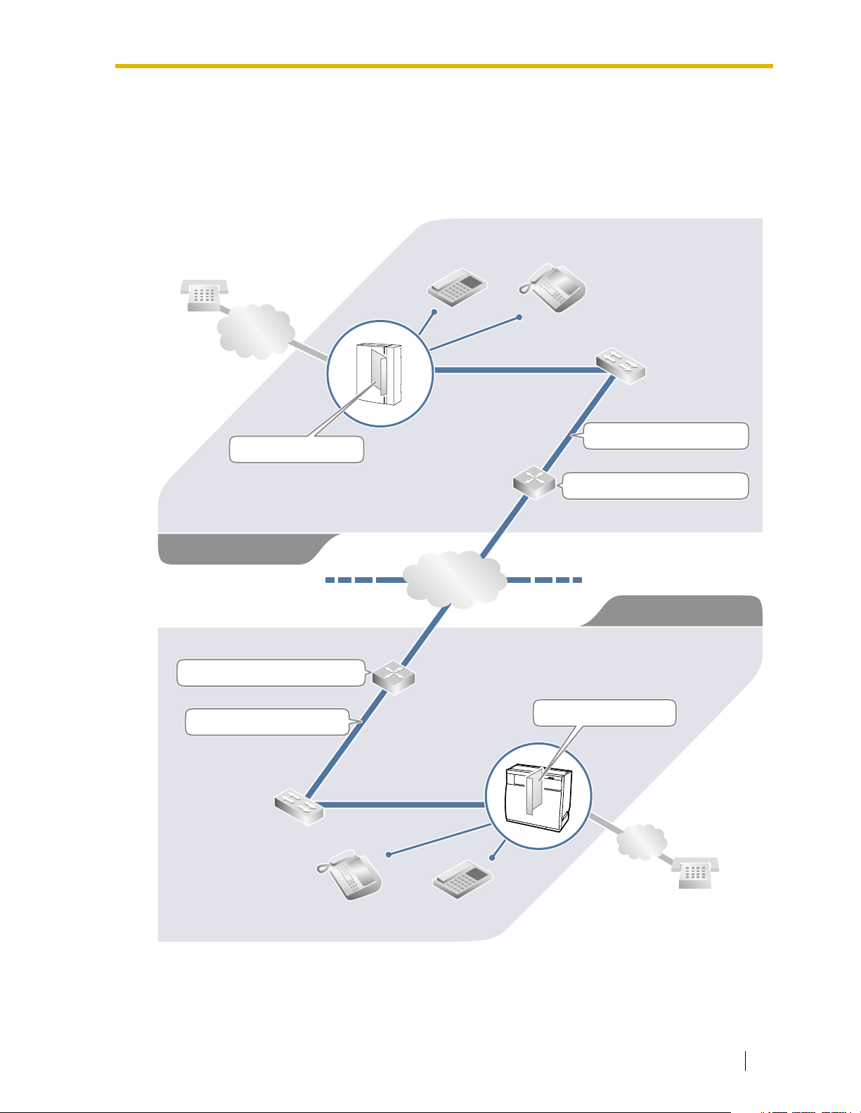
1.2 Network Devices and Numbering Plan
You will need to have network configuration information available to install VoIP Gateway
Cards. Referring to this example diagram, consult your network administrator to obtain
necessary information to configure your own VoIP network.
Local Telephone
456-7890
PSTN
(Public Switched
Telephone Network)
Card IP: 200.45.11.35
PBX Code: 35
PSTN Trunk (CO Line) Number: 9
TIE Line Access Number: 7
Los Angeles Office
Default Gateway IP: 199.176.64.1
Extn. 201
(200-299)
IP Network
G3 Fax Extn. 501
(500-599)
Subnet Mask: 255.255.255.0
Default Gateway IP: 200.45.11.1
Chicago Office
PBX Code: 41
PSTN Trunk (CO Line) Number: 9
TIE Line Access Number: 7
Subnet Mask: 255.255.255.0
G3 Fax Extn. 601
(600-699)
Extn. 301
(300-399)
Card IP: 199.176.64.41
PSTN
Local Telephone
123-4567
Getting Started 7
Page 8
1.2 Network Devices and Numbering Plan
1.2.1 Network Application
QSIG Network Interface
QSIG is a protocol based on ISDN (Q.931) that offers enhanced PBX features in a private
network. The QSIG network supports private communications by the TIE line service method.
Implementation of VoIP Gateway Cards provides a VoIP interface to employ a QSIG network
between PBXs at different locations by using an IP network instead of conventional telephone
networks.
Note
CLIP service is the only QSIG service available between the KX-TDA5480/KX-TDA0484
and KX-TDA0480 VoIP Gateway Cards. There is no compatibility for other QSIG services.
Types of IP Network
The VoIP Gateway Card’s quality of performance depends on the type of IP network in use.
Managed IP networks provide better quality of service compared to unmanaged networks such
as the Internet, where quality of service is not guaranteed.
Examples of recommended IP networks
• Digital Leased Line
• IP-VPN (Virtual Private Network)
•Frame Relay
Firewall
A firewall protects the internal networks of an organization against unauthorized penetration
from outside. When routing a VoIP network through a firewall, some performance degradation
may result. If for practical reasons you must route the VoIP network through a firewall, refer to
"A1.3 Network Devices" for more details.
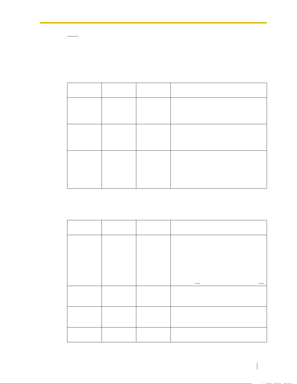
1.2.2 Numbering Plan Example
There are two methods to plan your numbering system, as follows:
In addition to the destination number, the caller dials the unique PBX code
PBX code
method
Extension
number method
of the PBX to which the called party is connected. Therefore, extension
numbers at separate PBXs in the network can overlap. For example, each
PBX in the network can have an extension whose number is 201.
The caller dials only the destination number of the called party to call
through PBXs at different locations (hence there are fewer digits to dial
than with the PBX code method). To employ the extension number
method, no two PBXs can have extensions sharing the same number. For
example, if one PBX in the network has an extension whose number is
201, no other PBX can have an extension with the same number (201).
Not recommended
• Internet
(Delays and loss in data transmission
can cause degradation in speech
quality.)
This section provides a network numbering mechanism using the PBX code method based on
the previous example diagram. Configure your network referring to this example.
8 Getting Started
Page 9
Note
An example using the extension number method is provided in "B Alternative Numbering
Plan Example".
IP Addressing Information
IP addressing information is typically supplied by a network administrator. Consult your
network administrator for specific values.
1.2 Network Devices and Numbering Plan
Los Angeles
Office
Card IP
Address
Default
Gateway
Address
Subnet Mask
Address
200.45.11.35 199.176.64.41
200.45.11.1 199.176.64.1
255.255.255.0 255.255.255.0
PBX Numbering Information
PBX numbering information is necessary to set up phone numbers for a VoIP network. Set the
numbers conforming to existing PBX numbering systems.
Los Angeles
Office
Chicago
Office
Chicago
Office
Description
Identifies the location of each VoIP Gateway
Card in the network during VoIP
communications. A unique IP address must
be assigned to each card.
Identifies the IP address of the primary
gateway (typically a router or similar device)
that exchanges IP packets with the other
gateways on the VoIP network.
Defines which digits of an IP address are
used for the network address and the host
address at each network location. A card IP
address must fall within the same subnet as
that of the default gateway (e.g., router) that
is connected to the card.
Description
PBX Code 35 41
TIE Line
Access
Number
PSTN Trunk
(CO Line)
Number
Extension
Number
77
99
200 to 299 300 to 399 A number assigned to each extension.
A unique number (ranging from 1 to 7 digits)
assigned to identify each PBX within a
network.
In this example, for convenience, each PBX
code corresponds to the last portion of the
IP address of its card; that is, because the
Los Angeles office card has the IP address
200.45.11.35
An access number to use the TIE line
service.
An access number to seize a local PSTN
trunk (CO line).
, Los Angeles PBX code is 35.
Getting Started 9
Page 10
1.2 Network Devices and Numbering Plan
Los Angeles
Office
Fax Extension
Number
500 to 599 600 to 699 A number assigned to each fax extension.
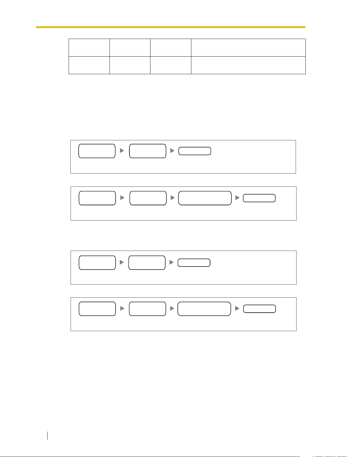
Dialing Examples
The VoIP network allows you to access the PBX at one location from another to establish: (1)
an extension call, or (2) an outside call through the local PSTN as if you are calling from the
same area.
Calling from Los Angeles to Chicago
To extension 301 via VoIP network
TIE line
access no.
To local telephone 123-4567 via VoIP network through local PSTN
TIE line
access no.
Chicago
PBX code
Dial 41.Dial 7. Dial 301.
Chicago
PBX code
Chicago
Office
Description
extension no.
Chicago PBX
PSTN trunk (CO line) no.
phone no.
Dial 41. Dial 9.Dial 7. Dial 123-4567.
Calling from Chicago to Los Angeles
To extension 201 via VoIP network
TIE line
access no.
To local telephone 456-7890 via VoIP network through local PSTN
TIE line
access no.
Los Angeles
PBX code
Dial 35.Dial 7. Dial 201.
Los Angeles
PBX code
Dial 35. Dial 9.Dial 7. Dial 456-7890.
extension no.
Los Angeles PBX
PSTN trunk (CO line) no.
phone no.
10 Getting Started
Page 11
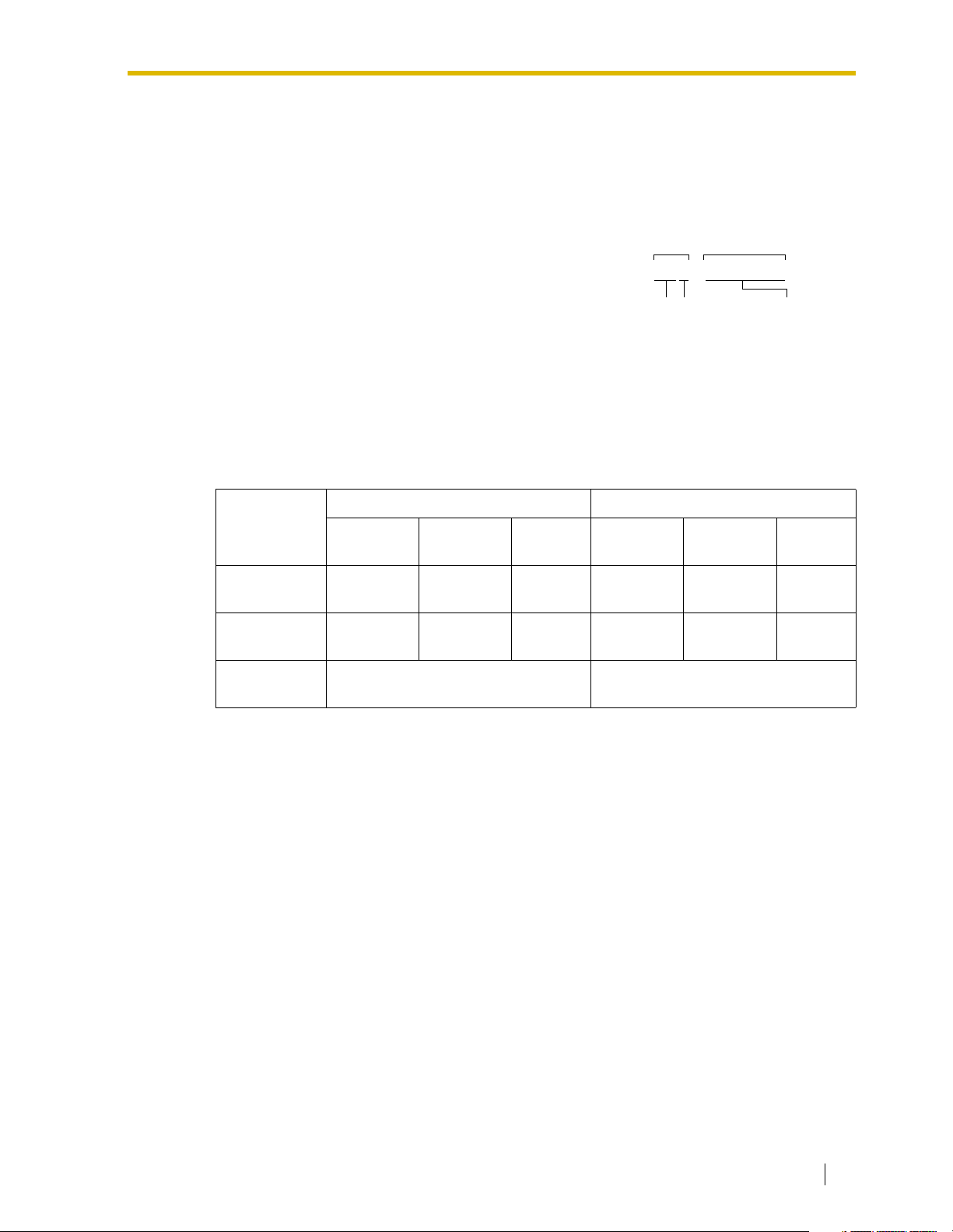
PBX Connection Information
PBX connection information is created by combining IP Addressing Information and PBX
Numbering Information. Referring to the sample below, create your own PBX connection
information.
1.2 Network Devices and Numbering Plan
Leading Number:
Los Angeles extensions
A number composed of the PBX code followed by the first
digit of the destination number. See the example on the
right.
Remaining Digits:
The maximum number of digits to be dialed following the
352+00 to 99
PBX Code
First digit of
the extension
number
leading number to access the destination. (However, for
example, setting the remaining digits to 7 does not mean
that the user must dial all 7 digits when making a call.)
See the example on the right.
Card IP Address:
The IP address of each card in the network (as the access destination).
Los Angeles Office (PBX Code: 35) Chicago Office (PBX Code: 41)
Leading
Number
Remaining
Digits
Extensions FAX
Extensions
352 355 359 413 416 419
227227
PSTN
Access
Extensions FAX
Extensions
Remaining DigitsLeading No.
Remaining digits
of the extension
number
PSTN
Access
Card IP
Address
200.45.11.35 199.176.64.41
Getting Started 11
Page 12
1.2 Network Devices and Numbering Plan
1.2.3 Numbering Plan Summary
Reproduce this page and write down your network information in the space provided below for
each card in the network. Consult your network administrator to fill in the shaded entries.
Local Telephone:
PSTN
(Public Switched
Telephone Network)
Card IP:
PBX Code:
PSTN Trunk (CO Line) Number:
TIE Line Access Number:
IP Address
Extension Number:
IP Network
G3 Fax Extension Number:
Subnet Mask:
Default Gateway IP:
PBX Numbering
Card IP Address
Default Gateway IP Address
Subnet Mask Address
PBX Connection
Leading Number
Remaining Digits
Card IP Address
Extensions
PBX Code
TIE Line Access Number
PSTN Trunk (CO Line) Number
Extension Number
Fax Extension Number
PSTN AccessFax Extensions
12 Getting Started
Page 13

Section 2
Installing in the KX-TDA50 PBX
This section describes the physical installation process
of the KX-TDA5480 VoIP Gateway Card covering the
following topics: (1) installing the card in the KX-TDA50
PBX, and (2) connecting the card to a network device
using a category 5 (CAT 5) Ethernet cable.
Getting Started 13
Page 14
2.1 Installation
2.1 Installation
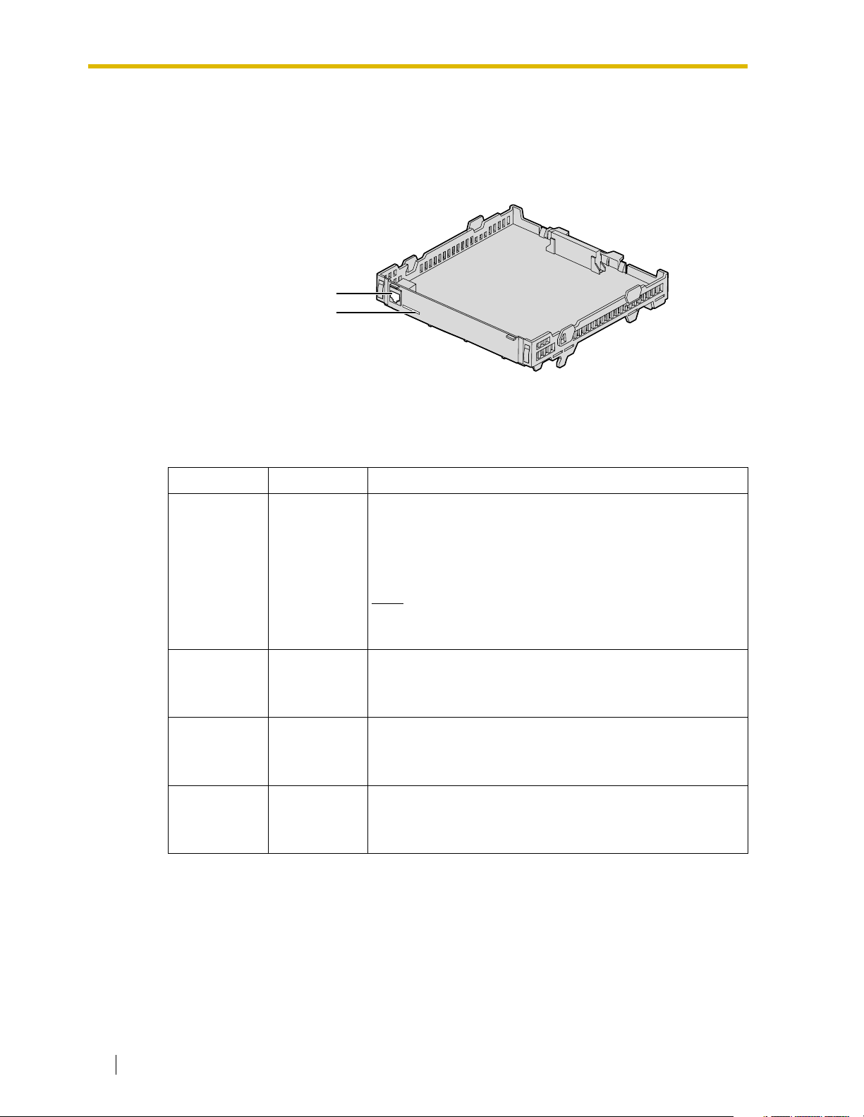
2.1.1 Names and Locations
RJ45
(10BASE-T/100BASE-TX)
LEDs
Indication Light (LED)
When the VoIP Gateway Card is operating, each LED should show the status identified in boldface letters under normal conditions.
Indication Color Description
On-line status indication
• ON: On-line mode
• OFF: Off-line mode
ONLINE Green
ALARM Red
LINK Green
DATA Green
• Flashing: Maintenance mode
Note
If the LINK indicator is OFF, the ONLINE indicator will
also be OFF.
Alarm indication
• ON: Alarm
• OFF: Normal
Link status indication
• ON: Normal connection
• OFF: Connection error
Data transmission indication
• ON: Data transmitting
• OFF: No data transmitted
14 Getting Started
Page 15
2.1.2 Installing the VoIP Gateway Card in the PBX
Install the VoIP Gateway Card in slot 05, 06, or 07 of the KX-TDA50 PBX.
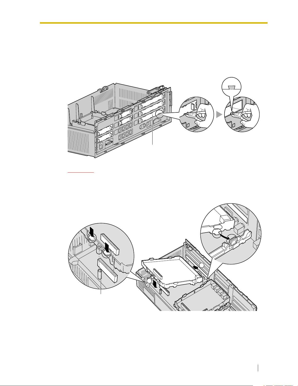
1. Before installing the card, cut and remove the dummy cover plate for the appropriate slot
from the main unit.
Dummy Cover Plate
2.1 Installation
CAUTION
For safety reasons, smooth the cut edges after removing the dummy cover plate.
2. Position the card in the open slot, making sure that the tabs on both sides of the card fit
into place. Then, holding the card firmly in place, lower the rear end so that the hole of the
card fits over the extension bolt.
1
2
Extension Bolt
Getting Started 15
Page 16
2.1 Installation
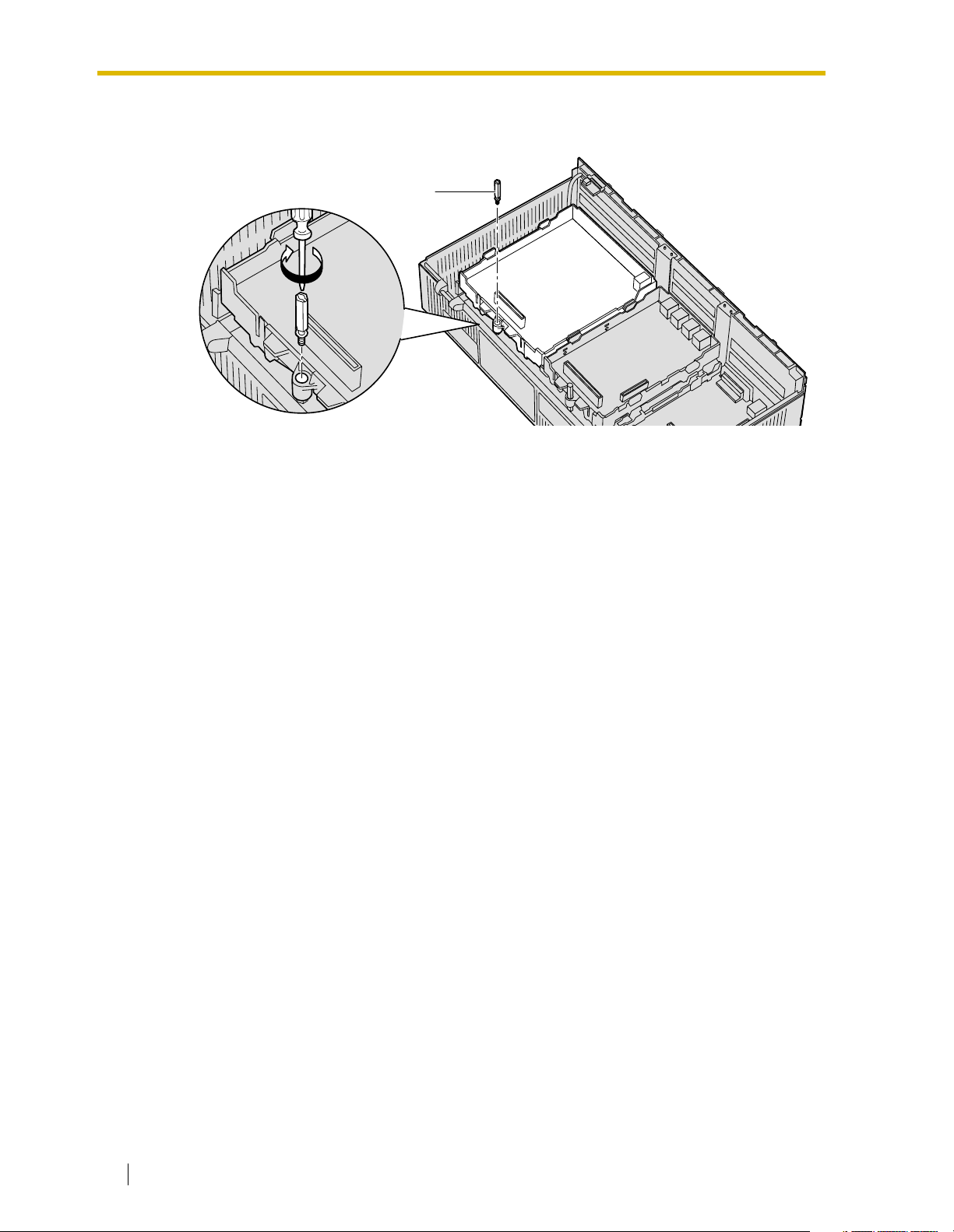
3. Insert the new extension bolt (included with the card) into the hole on the card, and tighten
it to secure the card.
Extension Bolt
16 Getting Started
Page 17
2.2 Cable Connection
Use a category 5 (CAT 5) Ethernet cable (10BASE-T/100BASE-TX) with an RJ45 connector
to connect the VoIP Gateway Card to a network device.
When connecting the card to a switching hub, use an Ethernet straight cable; when connecting
directly to a router or PC, use an Ethernet cross cable.
Note
Use only CAT 5 Ethernet cable for connection.
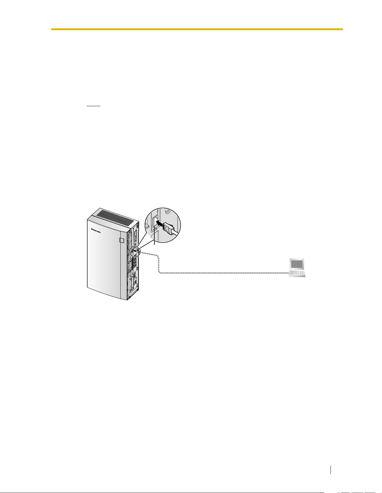
2.2.1 Connection for Programming
When assigning a new IP address to the VoIP Gateway Card for the first time, connect a PC
directly to the card using an Ethernet cross cable.
1. Connect the Ethernet cable to the RJ45 connector of the card.
2. Connect the other end of the cable to the PC.
2.2 Cable Connection
RJ45
Ethernet Cross Cable
PC
Getting Started 17
Page 18
2.2 Cable Connection
2.2.2 Connection to the LAN
Do not connect the VoIP Gateway Card to the LAN unless it has been assigned an IP address
for actual VoIP operations on the network. Doing so may result in the default IP address of the
card overlapping with an existing IP address on the LAN, or cause network failure.
1. Connect the Ethernet cable to the RJ45 connector of the card.
2. Connect the other end of the cable to the remote LAN equipment.
Connecting to a switching hub
RJ45
Ethernet Straight Cable
Connecting directly to a router
RJ45
Switching Hub
Ethernet Cross Cable
Router
PC
Router
18 Getting Started
Page 19

Section 3
Installing in the KX-TDA100/KX-TDA200 PBX
This section describes the physical installation process
of the KX-TDA0484 VoIP Gateway Card covering the
following topics: (1) installing the card in the KXTDA100/KX-TDA200 PBX, and (2) connecting the card
to a network device using a category 5 (CAT 5)
Ethernet cable.
Getting Started 19
Page 20
3.1 Installation
3.1 Installation
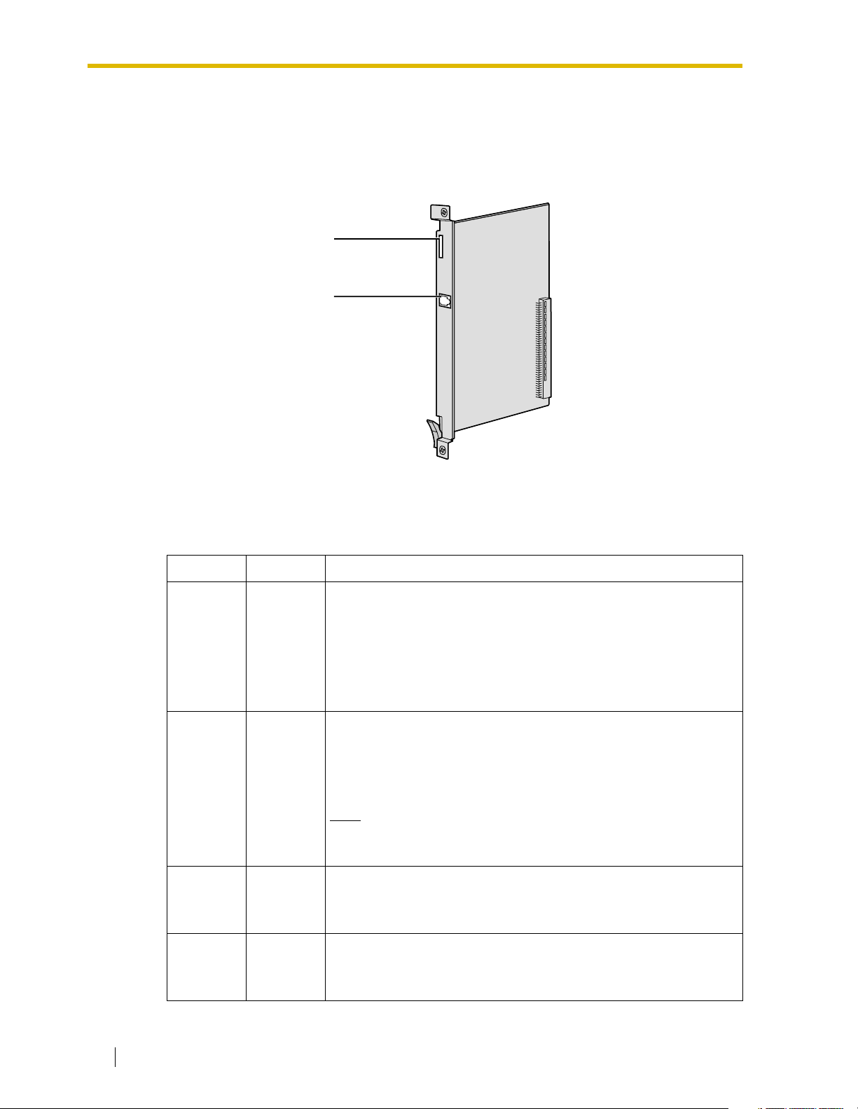
3.1.1 Names and Locations
LEDs
RJ45
(10BASE-T/100BASE-TX)
Indication Light (LED)
When the VoIP Gateway Card is operating, each LED should show the status identified in boldface letters under normal conditions.
Indication Colour Description
CARD
STATUS
ONLINE Green
ALARM Red
Green/Red
Card status indication
• OFF: Power Off
• Green ON: Normal (all ports are idle)
• Green Flashing (60 times per minute): Normal (a port is in use)
• Red ON: Fault (includes reset)
• Red Flashing (60 times per minute): Out of Service
On-line status indication
• ON: On-line mode
• OFF: Off-line mode
• Flashing: Maintenance mode
Note
If the LINK indicator is OFF, the ONLINE indicator will also be
OFF.
Alarm indication
• ON: Alarm
• OFF: Normal
VoIP BUSY Green
20 Getting Started
VoIP (H.323) process indication
• OFF: VoIP process inactive
• ON: VoIP process active
Page 21
Indication Colour Description
Link status indication
LINK Green
DATA Green
• ON: Normal connection
• OFF: Connection error
Data transmission indication
• ON: Data transmitting
• OFF: No data transmitted
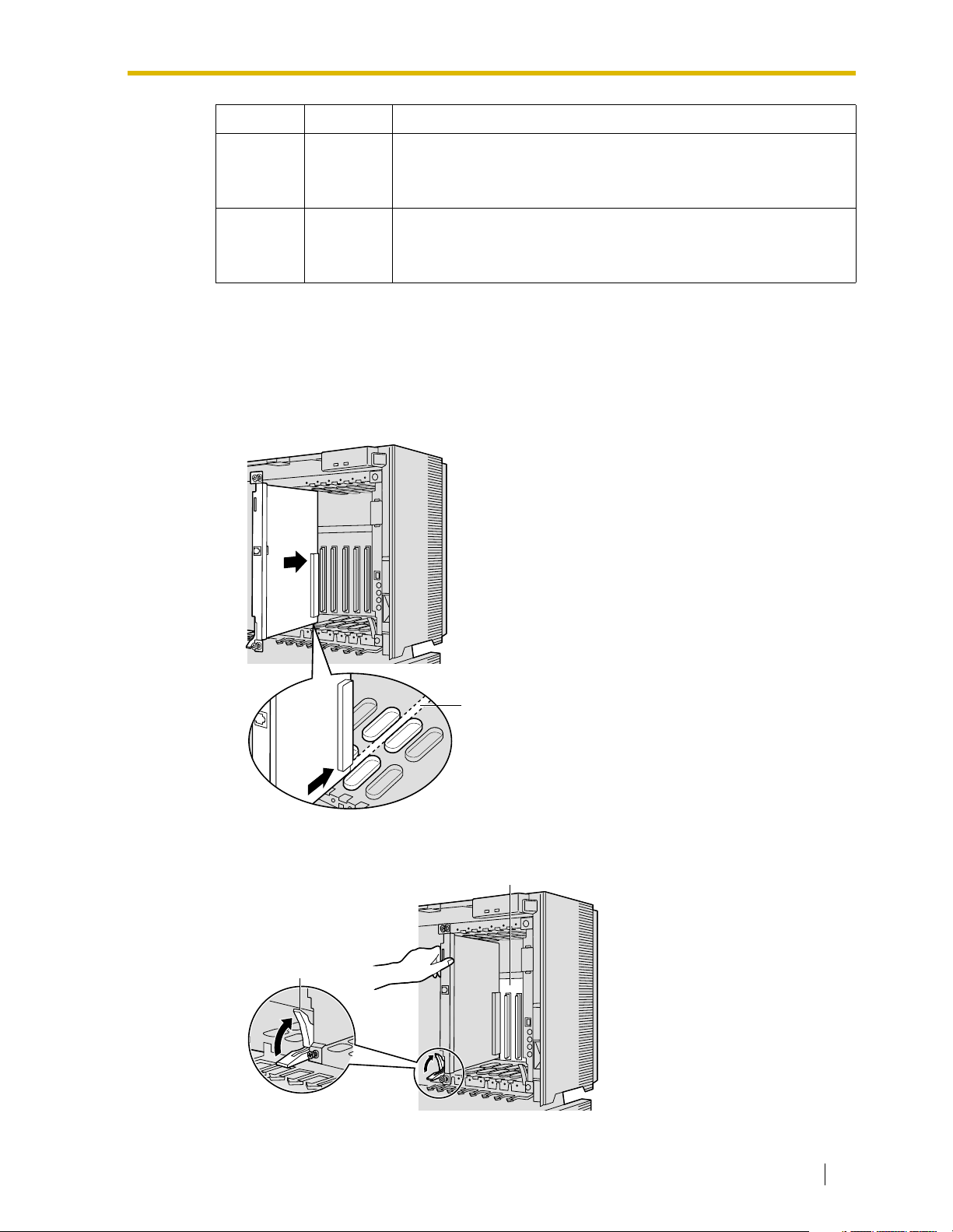
3.1.2 Installing the VoIP Gateway Card in the PBX
Install the VoIP Gateway Card in a free slot of the KX-TDA100/KX-TDA200 PBX.
1. Insert the card along the guide rails.
3.1 Installation
Guide Rail
2. Holding the card as shown below, push the release lever in the direction of the arrow so
that the card engages securely with the connector on the back board.
Back Board
Release Lever
Getting Started 21
Page 22
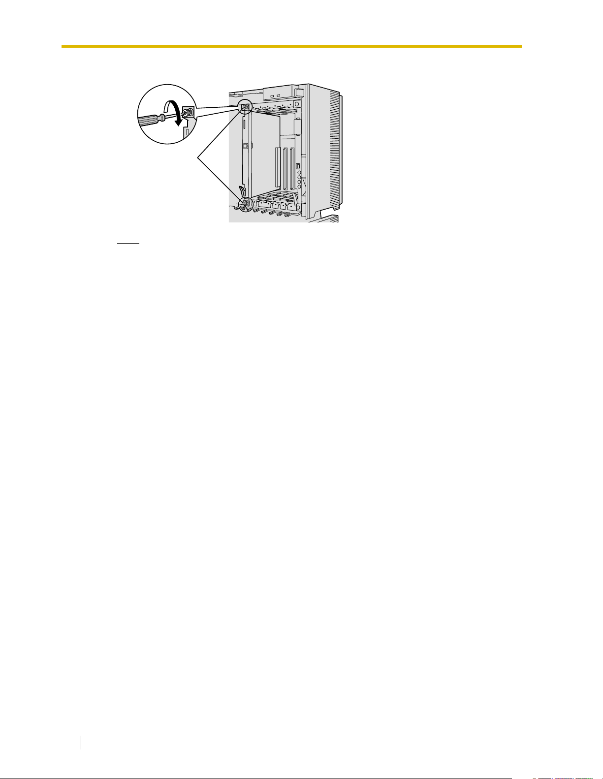
3.1 Installation
3. Turn the 2 screws clockwise to fix the card in place.
Screws
Note
Make sure the screws are tightened to ground the card securely.
22 Getting Started
Page 23
3.2 Cable Connection
Use a category 5 (CAT 5) Ethernet cable (10BASE-T/100BASE-TX) with an RJ45 connector
to connect the VoIP Gateway Card to a network device.
When connecting the card to a switching hub, use an Ethernet straight cable; when connecting
directly to a router or PC, use an Ethernet cross cable.
Note
Use only CAT 5 Ethernet cable for connection.
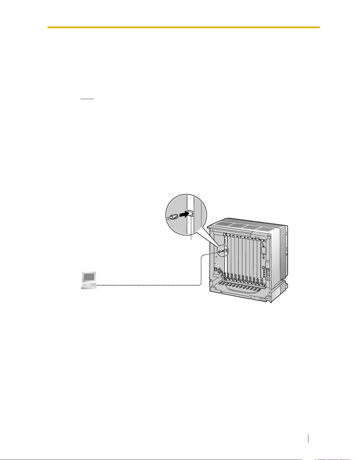
3.2.1 Connection for Programming
When assigning a new IP address to the VoIP Gateway Card for the first time, connect a PC
directly to the card using an Ethernet cross cable.
1. Connect the Ethernet cable to the RJ45 connector of the card.
2. Connect the other end of the cable to the PC.
3.2 Cable Connection
PC
RJ45
Ethernet Cross Cable
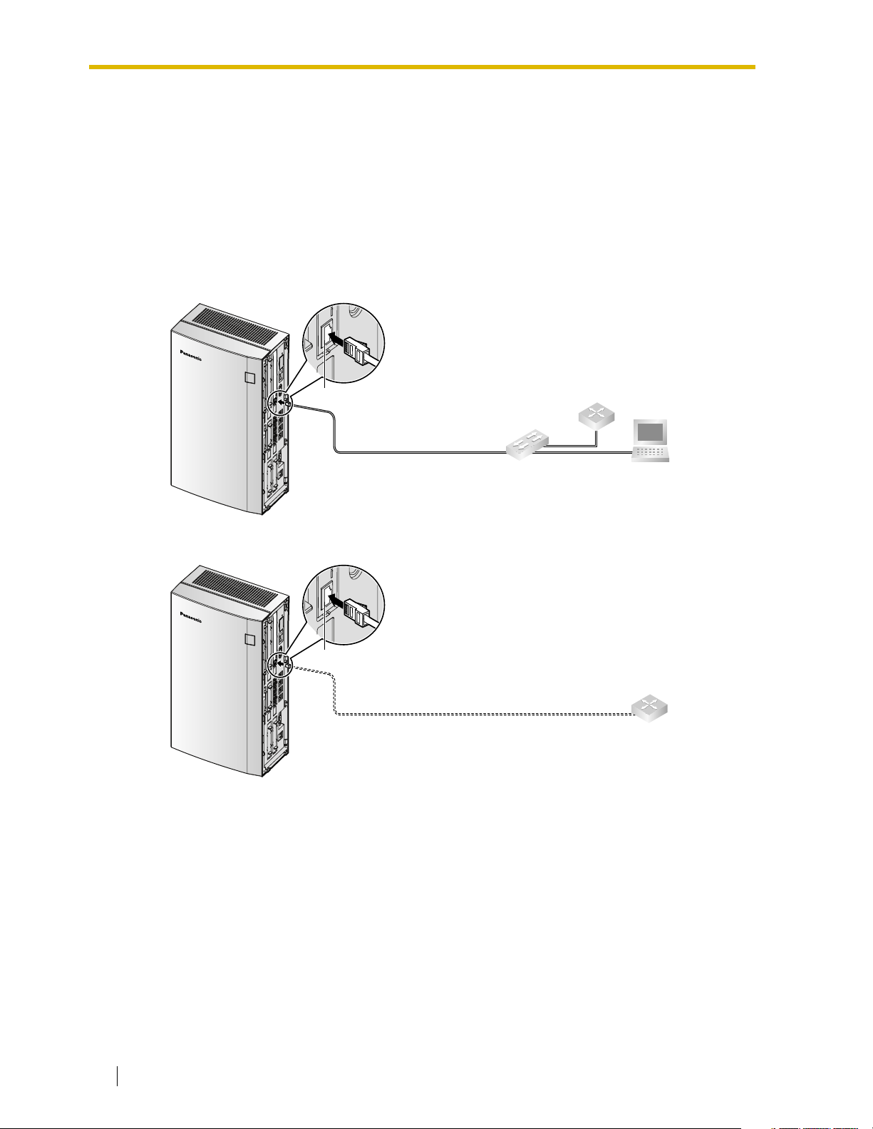
Getting Started 23
Page 24

3.2 Cable Connection
3.2.2 Connection to the LAN
Do not connect the VoIP Gateway Card to the LAN unless it has been assigned an IP address
for actual VoIP operations on the network. Doing so may result in the default IP address of the
card overlapping with an existing IP address on the LAN, or cause network failure.
1. Connect the Ethernet cable to the RJ45 connector of the card.
2. Connect the other end of the cable to the remote LAN equipment.
Connecting to a switching hub
Router
RJ45
Switching Hub
PC
Ethernet Straight Cable
Connecting directly to a router
Router
Ethernet Cross Cable
RJ45
24 Getting Started
Page 25

Section 4
Programming the VoIP Gateway Card
One way of setting up a VoIP network for the first time
is to go through the whole programming process of a
VoIP Gateway Card at one location in the network, then
start programming the other cards at different locations.
Based on the theoretical network illustrated previously
in this manual, this section demonstrates the procedure
to program the cards in the Los Angeles and Chicago
offices.
Getting Started 25
Page 26

4.1 Preparations
4.1 Preparations
A web programming utility called the IP-GW4 Maintenance Utility is available for programming
of the VoIP Gateway Card.
For a complete discussion of web programming, refer to the VoIP Gateway Card Programming
Guide.
System Requirements
• The IP-GW4 Maintenance Utility requires Microsoft® Internet Explorer 5.0 or above.
Trademarks
• Microsoft is either a registered trademark or trademark of Microsoft Corporation in the
United States and/or other countries.
• All other trademarks identified herein are the property of their respective owners.
• Screen shots reprinted with permission from Microsoft Corporation.
4.1.1 Preparing the PC
To prepare for programming using the IP-GW4 Maintenance Utility, configure your PC by (1)
assigning an IP address that belongs to the same network as that of the VoIP Gateway Card,
and (2) choosing the appropriate options for the Internet properties.
Note
The procedure below is based on the Windows XP operating system as an example.
1. Open Internet Protocol (TCP/IP) Properties
from the Start menu.
2.
a. Click Use the following IP address.
b. In the IP address box, type
192.168.1.100.
This is an example entry for the case
when the card has the default IP address
(192.168.1.200).
c. In the Subnet mask box, type
255.255.255.0.
d. Click OK.
26 Getting Started
3.
a. Start Internet Explorer from the Start
menu.
b. Click Internet Options from the Tools
menu.
Page 27

4.
a. Click the Connections tab.
b. Click Never dial a connection.
c. Click LAN Settings.
5.
a. Click to clear all check boxes.
b. Click OK.
4.1 Preparations
Your PC is now ready for programming
through direct access to the card.
Notice When Programming the Card through an IP Network
When the card is put in actual operation on an IP network, you can access and program the
card through the network. However, if the network has a proxy server installed, you must apply
appropriate proxy settings to your PC. In this case, follow the steps below in substitution for
step 5 above:
5. Click Advanced.
Getting Started 27
Page 28

4.1 Preparations
6.
a. Under Do not use proxy server for
addresses beginning with:, type the IP
address of the card.
b. Click OK.
Your PC is now ready for programming the
card through an IP network.
28 Getting Started
Page 29

4.2 Programming the VoIP Gateway Card in the Los Angeles Office
4.2 Programming the VoIP Gateway Card in the
Los Angeles Office
Based on the example network in "1.2 Network Devices and Numbering Plan", this section
demonstrates the procedure to program a VoIP Gateway Card for use in the Los Angeles office,
as the first step of setting up a VoIP network. VoIP communications between the two offices
will be possible when the cards, as well as the PBXs, in both offices are fully programmed.
The procedure to program the card in the Chicago office is given in "4.3 Programming the VoIP
Gateway Card in the Chicago Office". In addition, the procedure to program the PBXs is given
in "5 Programming the PBX".
4.2.1 Starting the IP-GW4 Maintenance Utility
Make sure that a PC is connected directly to the VoIP Gateway Card with an Ethernet cross
cable (see "2.2.1 Connection for Programming" or "3.2.1 Connection for Programming").
The card should not be connected to the LAN at this point.
1. Start Internet Explorer from the Start menu.
2.
a. In the Address box of Internet Explorer,
type http://192.168.1.200 (default IP
address of the card).
b. Press the ENTER key on the keyboard.
Notes
• If you cannot see the log-in screen,
return to "4.1.1 Preparing the PC"
and confirm that your PC has been
configured appropriately.
• If you forget the IP address, you
must initialize the card to the default
setting (see "C1 Initializing the VoIP
Gateway Card").
3.
a. In the Username box, type
Administrator (default user name).
b. In the Password box, type
Administrator (default password).
c. Click LOGIN.
Note
If you forget the user name or password,
you must initialize the card to the default
setting (see "C1 Initializing the VoIP
Gateway Card").
Getting Started 29
Page 30

4.2 Programming the VoIP Gateway Card in the Los Angeles Office
The main menu appears.
Note
Note
If you finish a programming session without logging out from the card (e.g., quitting
Internet Explorer, or returning to the log-in screen with the "Back" button of Internet
Explorer), you cannot log in again for the period of time specified by the parameter
Programming Auto Disconnect Time (default: 10 min).
For the log-out procedure and Programming Auto Disconnect Time setting, refer to
"2.5.2 Log Out" and "2.3.2 Maintenance Settings" of the VoIP Gateway Card Programming
Guide, respectively.
For readability of the text on the screen,
it is recommended that you adjust the
text size of Internet Explorer to below
medium.
30 Getting Started
Page 31

4.2 Programming the VoIP Gateway Card in the Los Angeles Office
4.2.2 Changing the Status of the VoIP Gateway Card
When programming the VoIP Gateway Card, place the card in the "STOP" status.
1. Click 2.1 Change RUN/STOP status in the
main menu.
2.
a. Click STOP for Status after changing.
b. Click OK.
3. Click OK.
4. Click OK.
Getting Started 31
Page 32

4.2 Programming the VoIP Gateway Card in the Los Angeles Office
4.2.3 Assigning the IP Address
When programming the VoIP Gateway Card for the first time, a new IP address must be
assigned. Once this is done and the card is on-line, it will be able to communicate with the other
cards over the VoIP network.
The specific setting values are based on the table under "IP Addressing Information" in "1.2.2
Numbering Plan Example".
1. Click 1.1 Network Settings, General in the
main menu.
2.
a. In the IP Address box, type
200.45.11.35.
b. In the Subnet Mask box, type
255.255.255.0.
c. In the Default Gateway box, type
200.45.11.1.
d. Click OK.
3. Confirm your entry, and then click OK.
Note
For more details about IP address assignment, refer to "2.2.1 Network Parameters" of the
VoIP Gateway Card Programming Guide.
32 Getting Started
Page 33

4.2 Programming the VoIP Gateway Card in the Los Angeles Office
4.2.4 Assigning the Hunt Pattern
The hunt pattern determines how to route incoming calls through the VoIP Gateway Card to
the PBX.
1. Click 1.5 Hunt Pattern (for Incoming Calls)
in the main menu.
2.
a. In the Hunt Pattern No. box, type 1.
A hunt pattern will be created with this
numbering.
b. In the Receive Leading Number box,
type 35 (PBX code).
c. Click ENTRY.
d. Click OK.
3. Confirm your entry, and then click OK.
Note
For more details about hunt pattern assignment, refer to "2.2.5 Hunt Pattern Parameters"
of the VoIP Gateway Card Programming Guide.
Getting Started 33
Page 34

4.2 Programming the VoIP Gateway Card in the Los Angeles Office
4.2.5 Programming the Address Translation Table
The function of an address translation table in a VoIP network is to provide two-way translation
*1
of telephone numbers and IP addresses
VoIP Gateway Cards in the network. Therefore, whenever the address translation table is
changed, it is important to update all the cards in the network with the latest information;
otherwise VoIP communications cannot be established.
It is possible, at one location in the network, to program the address translation table that
contains information for the entire network. The completed address translation table can then
be distributed across the network, so that all the cards share the same information (see "4.2.6
Downloading the Address Translation Table from the VoIP Gateway Card", and "Uploading
Address Translation Table to the VoIP Gateway Card" in "4.3 Programming the VoIP Gateway
Card in the Chicago Office").
The procedure below demonstrates the process of programming the address translation table
necessary for VoIP communications between the Los Angeles and Chicago offices.
The specific setting values are based on the table under "PBX Connection Information" in
"1.2.2 Numbering Plan Example".
. The address translation table is owned jointly by all
1. Click 1.6 DN2IP (Dialed Number to IP
Address Translation) in the main menu.
2. Click 1.6.1 GW Entry.
*1
IP address-to-telephone number translation can also be handled by using an H.323 Gatekeeper device. To configure Gatekeeper
devices, refer to the manufacturer’s documentation. This manual focuses on the method using the VoIP Gateway Card’s internal
address translation capabilities.
34 Getting Started
Page 35

4.2 Programming the VoIP Gateway Card in the Los Angeles Office
3. Do the following to configure the gateway
entry for the Los Angeles office:
a. In the GW No. box, type 0.
A gateway entry for the card will be
created with this numbering.
b. In the Comment box, type Los Angeles
(a unique identifier of the card in the VoIP
network).
c. In the IP Address box, type
200.45.11.35.
d. In the Group No. box, type 0.
Note
Having the value 0 for Group No. means
that the card does not belong to any
gateway group. Grouping is useful when
installing multiple cards at one location.
For details, refer to "2.2.6 Address
Tra ns l at io n Tab l e—GW Entry" of the
VoIP Gateway Card Programming
Guide.
e. Click ENTRY.
4. Do the following to configure the gateway
entry for the Chicago office:
a. In the GW No. box, type 1.
b. In the Comment box, type Chicago.
c. In the IP Address box, type
199.176.64.41.
d. In the Group No. box, type 0.
e. Click ENTRY.
f. Click OK.
5. Confirm your entry, and then click OK.
The gateway entries for the Los Angeles and
Chicago offices are now configured.
Getting Started 35
Page 36

4.2 Programming the VoIP Gateway Card in the Los Angeles Office
6. Click PREVIOUS.
7. Click 1.6.2 DN2IP Entry.
8. Do the following to configure the Los Angeles
extensions:
a. In the Leading Number box, type 352
(PBX code [35] + extension starting digit
[2]).
b. In the Remaining Number of Digits
box, type 2 (2 digits to dial [00 to 99]
following the leading number).
c. Click GW for GW No/Group No.
Selection.
d. In the GW No/Group No. box, type 0 (the
gateway entry for the card).
e. Click ENTRY.
9.
a. Referring to step 8, complete the
address translation table as shown on
the left.
b. Click OK.
c. Confirm your entry, and then click OK.
Note
For more details about address translation programming, refer to "2.2.6 Address
Translation Table—GW Entry" and "2.2.7 Address Translation Table—DN2IP Entry" of the
VoIP Gateway Card Programming Guide.
36 Getting Started
Page 37

4.2 Programming the VoIP Gateway Card in the Los Angeles Office
4.2.6 Downloading the Address Translation Table from the VoIP Gateway Card
After the address translation table has been fully programmed, download the data from the
VoIP Gateway Card.
The downloaded data can be uploaded to the other cards on the VoIP network (see "Uploading
Address Translation Table to the VoIP Gateway Card" in "4.3 Programming the VoIP Gateway
Card in the Chicago Office"), so that all the cards can communicate with each other over the
network.
1. Click 3.4 Download of DN2IP data (VoIP
Gateway –> PC) in the main menu.
2.
a. Click DOWNLOAD.
b. Specify the file name and the folder in
which to save the file.
Note
For more details about downloading the address translation table, refer to "2.4.4 Download
of Address Translation Table" of the VoIP Gateway Card Programming Guide.
Getting Started 37
Page 38

4.2 Programming the VoIP Gateway Card in the Los Angeles Office
4.2.7 Rebooting the VoIP Gateway Card
For all the changes to the parameters to become effective, you must reboot the VoIP Gateway
Card.
1. Click REBOOT in the main menu.
2. Click REBOOT.
38 Getting Started
Page 39

4.2 Programming the VoIP Gateway Card in the Los Angeles Office
4.2.8 Confirming the IP Address Assignment
After programming of the VoIP Gateway Card is finished, try to access the card with the new
IP addressing information. If you can connect to the card without problems, the card can be
placed on the LAN for VoIP operations (see "2.2.2 Connection to the LAN" or "3.2.2 Connection
to the LAN").
Follow the procedure below, referring to "4.1.1 Preparing the PC" and "4.2.1 Starting the IPGW4 Maintenance Utility".
1. Set the IP address settings of the PC to the following values:
• IP address: 200.45.11.100
• Subnet Mask address: 255.255.255.0
2. Start Internet Explorer from the Start menu.
3. In the Address box of Internet Explorer, type http://200.45.11.35 (the new IP address of
the card).
4. Press the ENTER key on the keyboard.
If you can log in, then the card has been successfully programmed.
After you have confirmed that the card has been successfully programmed, it is strongly
recommended that you download the configuration data from the card and save it on your PC
for backup and archive purposes.
The procedure for downloading the configuration data is provided in "2.4.2 Download of
Configuration Data" of the VoIP Gateway Card Programming Guide.
Getting Started 39
Page 40

4.3 Programming the VoIP Gateway Card in the Chicago Office
4.3 Programming the VoIP Gateway Card in the
Chicago Office
This section details the procedure to program the VoIP Gateway Card in the Chicago office,
which for the most part is a duplication of that for the Los Angeles office. For general
information that is not discussed here, refer to the relevant sections in "4.2 Programming the
VoIP Gateway Card in the Los Angeles Office".
There are differences in the procedure where distinct setting values are required for
parameters that are dependent on the specific network configuration of the Chicago office.
Also, the address translation table does not need to be programmed, because the one
downloaded from the card in the Los Angeles office already contains the information for the
entire network. You can simply upload the address translation table from the Los Angeles
office, and the cards can communicate with each other on the network.
Starting the IP-GW4 Maintenance Utility
1. Start Internet Explorer from the Start menu.
2.
a. In the Address box of Internet Explorer,
type http://192.168.1.200 (default IP
address of the card).
Make sure that the PC has the
appropriate IP address setting to access
the card (refer to "4.1.1 Preparing the
PC").
b. Press the ENTER key on the keyboard.
3.
a. In the Username box, type
Administrator (default user name).
b. In the Password box, type
Administrator (default password).
c. Click LOGIN.
The main menu appears.
Changing the Status of the VoIP Gateway Card
1. Click 2.1 Change RUN/STOP status in the
main menu.
2.
a. Click STOP for Status after changing.
b. Click OK.
c. Click OK.
d. Click OK.
40 Getting Started
Page 41

Assigning the IP Address
Note that the card in the Chicago office requires different IP address settings from the card in
the Los Angeles office.
4.3 Programming the VoIP Gateway Card in the Chicago Office
1. Click 1.1 Network Settings, General in the
main menu.
2.
a. In the IP Address box, type
199.176.64.41.
b. In the Subnet Mask box, type
255.255.255.0.
c. In the Default Gateway box, type
199.176.64.1.
d. Click OK.
3. Confirm your entry, and then click OK.
Assigning the Hunt Pattern
Note that the card in the Chicago office requires a different PBX code from the card in the Los
Angeles office.
1. Click 1.5 Hunt Pattern (for Incoming Calls)
in the main menu.
2.
a. In the Hunt Pattern No. box, type 1.
b. In the Receive Leading Number box,
type 41 (PBX code).
c. Click ENTRY.
d. Click OK.
3. Confirm your entry, and then click OK.
Getting Started 41
Page 42

4.3 Programming the VoIP Gateway Card in the Chicago Office
Uploading Address Translation Table to the VoIP Gateway Card
For the VoIP Gateway Cards in the Los Angeles and Chicago offices to communicate properly
over the VoIP network, the cards must share the same address translation table.
Follow the procedure below to upload the address translation table downloaded from the card
in the Los Angeles office (see "4.2.6 Downloading the Address Translation Table from the VoIP
Gateway Card") to the card in the Chicago office.
1. Click 3.3 Upload of DN2IP data (PC –> VoIP
Gateway) in the main menu.
2.
a. Click Browse and choose a file to
upload.
b. Click UPLOAD(PC–>VoIP Gateway).
3. Click REBOOT.
4. Click REBOOT.
42 Getting Started
Page 43

4.3 Programming the VoIP Gateway Card in the Chicago Office
Note
For more details about uploading the address translation table, refer to "2.4.3 Upload of
Address Translation Table" of the VoIP Gateway Card Programming Guide.
Confirming the IP Address Assignment
Note that the card in the Chicago has been assigned a different IP address from the card in the
Los Angeles office.
1. Set the IP address settings of the PC to the following values:
• IP address: 199.176.64.100
• Subnet Mask address: 255.255.255.0
2. Start Internet Explorer from the Start menu.
3. In the Address box of Internet Explorer, type http://199.176.64.41 (the new IP address of
the card).
4. Press the ENTER key on the keyboard.
If you can log in, then the card has been successfully programmed.
After you have confirmed that the card has been successfully programmed, it is strongly
recommended that you download the configuration data from the card and save it on your PC
for backup and archive purposes.
The procedure for downloading the configuration data is provided in "2.4.2 Download of
Configuration Data" of the VoIP Gateway Card Programming Guide.
Getting Started 43
Page 44

4.3 Programming the VoIP Gateway Card in the Chicago Office
44 Getting Started
Page 45

Section 5
Programming the PBX
For successful operation of a VoIP network using the
VoIP Gateway Card as a QSIG network interface, the
PBX at each location in the network must be
programmed appropriately. For a detailed discussion of
related features, refer to the Hybrid IP-PBX Feature
Guide.
This section details the procedure to program the PBX
to use the card.
Getting Started 45
Page 46

5.1 Programming the PBX in the Los Angeles Office
5.1 Programming the PBX in the Los Angeles
Office
This section details the procedure to program the PBX in the Los Angeles office. After the PBX
in the Los Angeles office has been fully programmed, repeat the procedure for the PBX in the
Chicago office with the appropriate setting values (see "5.2 Programming the PBX in the
Chicago Office").
Note
It is assumed that you have already installed the KX-TDA50 Maintenance Console (PC
programming software for the KX-TDA50 PBX) in your PC.
1. Start the KX-TDA50 Maintenance Console
from the Start menu.
2.
a. Type the Installer Level Programmer
Code (default: INSTALLER).
b. Click OK.
3.
a. Click Connect RS-232C or USB.
b. In the next screen, type the system
password for installer (default: 1234).
c. Click OK.
The program menu appears.
4.
a. Double-click Configuration.
b. Double-click IP-GW Port.
Confirm that ports 1 and 2 are in service
(INS).
5.
a. Double-click CO & Incoming Call.
b. Double-click CO Line Setting.
c. Type the CO Name and assign an
unused Trunk Group Number to be
used for all VoIP gateway trunks (CO
lines).
d. Click OK.
46 Getting Started
Page 47

5.1 Programming the PBX in the Los Angeles Office
6.
a. Double-click System.
b. Double-click Numbering Plan.
c. Double-click Feature.
d. In the Tie Line Access box, type the
dialing number.
e. Click OK.
7.
a. Double-click Private Network.
b. In the Own PBX Code box, type 35 (the
PBX code of the local PBX in the
network).
c. In the Leading Number box, type 41
(the PBX code of the remote PBX in the
network).
d. In the corresponding Trunk Group list,
click the number of the trunk (CO line)
group to be used when making calls.
e. Set the number modification pattern, if
necessary.
f. Click OK.
8.
a. Double-click Configuration.
b. Double-click Slot.
c. Click Status of the card.
d. Set the status to OUS.
e. Click Card Type of the card.
f. In the Val ue list, click Overlap (default)
*1
or En-bloc
.
g. Click OK.
h. Click Status of the card.
i. Set the status to INS.
*1
When "En-bloc" is selected, you need to press "#" after dialing the phone number.
Note
For details about network parameter settings, refer to the relevant sections of the Hybrid
IP-PBX Feature Guide.
Getting Started 47
Page 48

5.2 Programming the PBX in the Chicago Office
5.2 Programming the PBX in the Chicago Office
This section details the procedure to program the PBX in the Chicago office. Follow the same
procedure as you did for the PBX in the Los Angeles office, entering the setting values as
appropriate for the Chicago office.
Note
It is assumed that you have already installed the KX-TDA Maintenance Console (PC
programming software for the KX-TDA100/KX-TDA200 PBX) in your PC.
1. Start the KX-TDA Maintenance Console from
the Start menu.
2.
a. Type the Installer Level Programmer
Code (default: INSTALLER).
b. Click OK.
3.
a. Click Connect RS-232C or USB.
b. In the next screen, type the system
password for installer (default: 1234).
c. Click OK.
The program menu appears.
4.
a. Double-click Configuration.
b. Double-click IP-GW Port.
Confirm that ports 1 and 2 are in service
(INS).
5.
a. Double-click CO & Incoming Call.
b. Double-click CO Line Setting.
c. Type the CO Name and assign an
unused Trunk Group Number to be
used for all VoIP gateway trunks (CO
lines).
d. Click OK.
48 Getting Started
Page 49

5.2 Programming the PBX in the Chicago Office
6.
a. Double-click System.
b. Double-click Numbering Plan.
c. Double-click Feature.
d. In the Tie Line Access box, type the
dialing number.
e. Click OK.
7.
a. Double-click Private Network.
b. In the Own PBX Code box, type 41 (the
PBX code of the local PBX in the
network).
c. In the Leading Number box, type 35
(the PBX code of the remote PBX in the
network).
d. In the corresponding Trunk Group list,
click the number of the trunk (CO line)
group to be used when making calls.
e. Set the number modification pattern, if
necessary.
f. Click OK.
8.
a. Double-click Configuration.
b. Double-click Slot.
c. Click Status of the card.
d. Set the status to OUS.
e. Click Card Type of the card.
f. In the Val ue list, click Overlap (default)
*1
or En-bloc
.
g. Click OK.
h. Click Status of the card.
i. Set the status to INS.
*1
When "En-bloc" is selected, you need to press "#" after dialing the phone number.
Note
For details about network parameter settings, refer to the relevant sections of the Hybrid
IP-PBX Feature Guide.
Getting Started 49
Page 50

5.2 Programming the PBX in the Chicago Office
50 Getting Started
Page 51

Appendix A
Guidance for VoIP Installation
Getting Started 51
Page 52

A1 VoIP Requirements
A1 VoIP Requirements
A1.1 Bandwidth Assessment
To establish a VoIP network, you must ensure that the network has enough bandwidth to
support VoIP communications. Inform your network administrator of the required bandwidth,
and make sure that the network can support VoIP communications even under conditions of
maximum network traffic.
Bandwidth Calculation
Provided below is the formula to find out the amount of bandwidth required for VoIP
communications:
Required Bandwidth
= (No. of Fax Machines × Required Bandwidth for Fax Communication) +
[(4 - No. of Fax Machines) × Required Bandwidth for Voice Communication]
Required bandwidth for fax and voice communications for one VoIP channel is shown in the
tables below (for more details, refer to "2.2.3 Voice Communication Parameters" in the VoIP
Gateway Card Programming Guide).
Required Bandwidth for Voice Communication
Via LAN
CODEC
20 ms 30 ms 40 ms 60 ms 90 ms
G.711 87.2 kbps 79.5 kbps 75.6 kbps ——
G.729A 31.2 kbps 23.5 kbps 19.6 kbps ——
G.723.1 5.3 kbps — 20.8 kbps — 13.1 kbps 10.5 kbps
G.723.1 6.3 kbps — 21.9 kbps — 14.1 kbps 11.6 kbps
Via WAN (PPP: Point-to-Point Protocol)
CODEC
20 ms 30 ms 40 ms 60 ms 90 ms
G.711 84 kbps 77.3 kbps 74 kbps ——
G.729A 28 kbps 21 kbps 18 kbps ——
Packet Sending Interval
Packet Sending Interval
G.723.1 5.3 kbps — 18.7 kbps — 12 kbps 9.8 kbps
G.723.1 6.3 kbps — 19.7 kbps — 13.1 kbps 10.8 kbps
52 Getting Started
Page 53

Required Bandwidth for Fax Communication
Via LAN
A1 VoIP Requirements
Example
FAX High Reliable Method
G.711 Packet Sending Interval
20 ms 30 ms 40 ms
Don’t Use 87.2 kbps 79.5 kbps 75.6 kbps
Use 224.8 kbps 213.9 kbps 208.4 kbps
Via WAN (PPP: Point-to-Point Protocol)
G.711 Packet Sending Interval
FAX High Reliable Method
20 ms 30 ms 40 ms
Don’t Use 84 kbps 77.3 kbps 74 kbps
Use 221.6 kbps 211.7 kbps 206.8 kbps
Consider the following case as an example:
• Communication: via LAN
• No. of Fax Machines: 1
• Required Bandwidth for Fax Communication: 75.6 kbps
• Required Bandwidth for Voice Communication: 23.5 kbps
In this case, the required bandwidth will be as follows:
Required Bandwidth
= (1 × 75.6) + (3 × 23.5)
= 146.1
Therefore, inform your network administrator and make sure that the network can support a
bandwidth of 146.1 kbps even when the network is under conditions of maximum traffic.
Note
It is recommended that all VoIP Gateway Cards in a VoIP network have the same packet
sending interval.
A1.2 Network Configuration
You must evaluate the structure of the existing network to see if a VoIP network can be
implemented. Below are the points that should be taken into your evaluation.
Is the IP network a managed network?
A VoIP network should be implemented on a managed IP network such as Frame Relay,
Leased Line, or IP-VPN (Virtual Private Network).
An unmanaged network—that is, the Internet—cannot be used to employ a VoIP network
because delays and loss in data transmission can cause huge degradation in speech quality.
Getting Started 53
Page 54

A1 VoIP Requirements
Is it possible to have static IP addressing?
Because the maintenance of the VoIP Gateway Card is carried out from a personal computer
(PC) through an IP network, the card must be assigned a static IP address.
Static IP addressing must be made possible even when the DHCP feature is used. For more
details, refer to "2.2.1 Network Parameters" in the VoIP Gateway Card Programming Guide.
Is network address translation (NAT/NAPT) disabled?
In a network where address translation techniques (e.g., NAT/NAPT) are used to convert
between global and local IP addresses, VoIP communications based on the H.323 protocol
cannot be carried out appropriately. Generally, NAT/NAPT are features that are available with
routers.
IP Network
Global IP Address Domain
(NAT/NAPT enabled)
Router
Local IP Address Domain
Note
If the router on the network supports the "H.323 NAT" feature, it may be possible to have
VoIP communications over the network. For more information, consult your network
administrator.
54 Getting Started
Page 55

A1 VoIP Requirements
Does only a single router provide access to the IP network?
In a dual network, two routers provide access to the IP network as shown in the diagram below.
However, the VoIP Gateway Card cannot take the advantage of having two routers as access
points to the IP network.
For example, if router A, whose IP address is assigned as the default gateway IP address of
the card, fails, VoIP communications are no longer possible; the card is not able to switch its
default gateway from router A to router B to access the IP network. For more details about the
default gateway setting, refer to "2.2.1 Network Parameters" of the VoIP Gateway Card
Programming Guide.
IP Network
Router A Router B
Default gateway
of the card:
Router A
Getting Started 55
Page 56

A1 VoIP Requirements
Is there only a single IP network between two ends of a call?
A huge degradation in speech quality will be produced when calls are made through multiple
IP networks as shown below; therefore, it is recommended that you avoid establishing a VoIP
network in this fashion.
PSTN
IP Network 1 IP Network 2
IP Network 1 IP Network 2
56 Getting Started
Page 57

Is the card located appropriately?
Transmission delays can cause pauses and loss in VoIP communications. The more network
devices (e.g., routers and switches) there are between the communicating cards, the larger the
transmission delays, because a certain amount of delay is inevitable when packets go through
each network device (hop).
One preventative measure is to install the card so that the number of transmission hops is kept
to a minimum. In the diagram below, the card is located as close to the IP network interface as
possible.
A1 VoIP Requirements
Too many hops
Router
Switch
Switch
Hub
A1.3 Network Devices
You must evaluate the network devices that are used in the existing network to see if a VoIP
network can be implemented. Below are the points that should be taken into your evaluation.
Better
(PBX located nearest IP network access point)
Router
Switch
Switch
Hub
Can the firewall pass packets from the VoIP Gateway Card?
If the VoIP network contains a firewall, the firewall must be configured appropriately to allow
VoIP packets, which are listed in the table below, to pass through the network without being
blocked by filtering.
For more information, consult your network administrator.
Protocol TCP/UDP Default Port No.
*1
HTTP
RTP/RTCP
H.225.0 Call Signaling
H.245
H.225.0 RAS
*2
*2
*2
*2
*1 For the actual setting values, refer to "2.2.2 H.323 Parameters" in the VoIP Gateway Card
Programming Guide.
TCP 80
UDP 5004 to 5011
TCP 1720
TCP 1712 to 1724
UDP 1719
Getting Started 57
Page 58

A1 VoIP Requirements
*2 For the actual setting values, refer to "2.2.1 Network Parameters" in the VoIP Gateway
Card Programming Guide.
Are layer 2 or higher switches used?
Use of repeater hubs can increase the network load, and therefore may result in degradation
in speech quality.
To ensure the performance, it is strongly recommended that you use layer 2 or higher switches.
Are category 5 (CAT 5) cables used?
When connecting network devices, make sure to use CAT 5 cables. If other types of cables are
used, communications may not be carried out normally.
A1.4 QoS (Quality of Service)
Some routers permit the configuration of priority control features. This allows the router to give
higher priority to voice packets and lower the rate of loss and delays during transmissions,
hence improving speech quality. It is strongly recommended that you use this feature,
especially in networks where traffic is heavy.
Typically, a router identifies what packets to pass in priority by checking the value in the ToS
field of the header of IP packets. The VoIP Gateway Card has the ability to set the ToS field of
outgoing voice packets (see "2.2.3 Voice Communication Parameters" in the VoIP Gateway
Card Programming Guide). When the card is appropriately configured, the router can give
voice packets from the card higher priority.
Consult your network administrator when setting the ToS field, as the setting value must
conform to the router’s specifications.
Note
Some switches also permit the configuration of priority control features. For more
information, consult your network administrator.
58 Getting Started
Page 59

A2 VoIP Requirements Checklist
A2 VoIP Requirements Checklist
Use the following checklists to see if you can implement a VoIP network. The answers identified
in underlined bold-face letters
Bandwidth Assessment
No. Question Answer Memo Ref.
are the required answers for the corresponding questions.
Does the network have enough
bandwidth to support VoIP
communications?
1
Make sure that there is more bandwidth
available for VoIP communications than the
amount actually required.
• IP network bandwidth
= kbps
Yes
• Available bandwidth for VoIP
No
= kbps
• Required bandwidth for VoIP
= kbps
Network Configuration
No. Question Answer Memo Ref.
Is the IP network a managed network?
Make sure to use a managed IP network
such as Frame Relay, Leased Line, or IP-
2-a
VPN (Virtual Private Network). The VoIP
Gateway Card is not intended for use on
the Internet.
Is it possible to have static IP
2-b
addressing?
Is network address translation (NAT/
2-c
NAPT) disabled?
Type of IP network:
Yes
No
Yes
No
Yes
No
p. 52
p. 53
p. 54
p. 54
Does only a single router provide
2-d
access to the IP network?
Is there only a single IP network
2-e
between two ends of a call?
2-f Is the card located appropriately?
Yes
No
Yes
No
No. of hops (routers/switches)
Ye s
within one location:
No
p. 55
p. 56
p. 57
Getting Started 59
Page 60

A2 VoIP Requirements Checklist
Network Devices
No. Question Answer Memo Ref.
Can the firewall pass packets from the
Model of the firewall:
VoIP Gateway Card?
When a firewall is used, make sure to
3-a
configure the firewall appropriately to allow
VoIP packets to pass through the network
Yes
No
without being blocked by filtering.
Are layer 2 or higher switches used?
3-b
Do not use repeater hubs as they can
increase the network load.
3-c Are category 5 (CAT 5) cables used?
Model of the switch:
Yes
No
Yes
No
QoS (Quality of Service)
No. Question Answer Memo Ref.
Model of the router/switch:
Can the router or switch be configured
4
to use priority control features?
Ye s
VoIP Gateway Card’s ToS field
setting:
No
p. 57
p. 58
p. 58
p. 58
60 Getting Started
Page 61

Appendix B
Alternative Numbering Plan Example
Getting Started 61
Page 62

B1 Extension Number Method
B1 Extension Number Method
This section provides a numbering plan example using the extension number method, as
supplementary information to the PBX code method discussed in "1.2.2 Numbering Plan
Example".
B1.1 Example Network
The following diagram illustrates a simple VoIP network configured for the extension number
method.
Local Telephone
456-7890
PSTN
(Public Switched
Telephone Network)
Card IP: 200.45.11.35
PSTN Trunk (CO Line) Number: 92
VoIP Gateway Trunk (CO Line) Access Number: 802
Los Angeles Office
Default Gateway IP: 199.176.64.1
Extn. 201
(200-299)
IP Network
G3 Fax Extn. 501
(500-599)
Subnet Mask: 255.255.255.0
Default Gateway IP: 200.45.11.1
Chicago Office
PSTN Trunk (CO Line) Number: 93
VoIP Gateway Trunk (CO Line) Access Number: 803
Subnet Mask: 255.255.255.0
62 Getting Started
G3 Fax Extn. 601
(600-699)
Extn. 301
(300-399)
Card IP: 199.176.64.41
PSTN
Local Telephone
123-4567
Page 63

B1.2 Numbering Plan Example
IP Addressing Information
The following table is a duplication of the table used for the PBX code method.
B1 Extension Number Method
Los Angeles
Office
Card IP
Address
Default
Gateway
Address
Subnet Mask
Address
200.45.11.35 199.176.64.41
200.45.11.1 199.176.64.1
255.255.255.0 255.255.255.0
PBX Numbering Information
The following table contains "VoIP Gateway Trunk (CO Line) Access Number", instead of "PBX
Code" and "TIE Line Access Number" as used in the PBX code method.
Los Angeles
Office
Chicago
Office
Chicago
Office
Description
Identifies the location of each VoIP Gateway
Card in the network during VoIP
communications. A unique IP address must
be assigned to each card.
Identifies the IP address of the primary
gateway (typically a router or similar device)
that exchanges IP packets with the other
gateways on the VoIP network.
Defines which digits of an IP address are
used for the network address and the host
address at each network location. A card IP
address must fall within the same subnet as
that of the default gateway (e.g., router) that
is connected to the card.
Description
VoIP Gateway
Trunk (CO
Line) Access
Number
PSTN Trunk
(CO Line)
Number
Extension
Number
Fax Extension
Number
802 803
92 93
200 to 299 300 to 399 A number assigned to each extension.
500 to 599 600 to 699 A number assigned to each fax extension.
An access number to seize a VoIP gateway
trunk (CO line).
An access number to seize a local PSTN
trunk (CO line).
Getting Started 63
Page 64

B1 Extension Number Method
Dialing Examples
With the extension number method, the caller dials only the destination number of the called
party to call through PBXs at different locations.
Calling from Los Angeles to Chicago
To extension 301 via VoIP network
extension no.
Dial 301.
To local telephone 123-4567 via VoIP network through local PSTN
VoIP Gateway
trunk (CO line) access no.
PSTN trunk (CO line) no.
Calling from Chicago to Los Angeles
To extension 201 via VoIP network
extension no.
Dial 201.
To local telephone 456-7890 via VoIP network through local PSTN
VoIP Gateway
trunk (CO line) access no.
PSTN trunk (CO line) no.
PBX Connection Information
Los Angeles Office Chicago Office
Chicago PBX
Dial 93.Dial 802. Dial 123-4567.
Los Angeles PBX
Dial 92.Dial 803. Dial 456-7890.
phone no.
phone no.
Leading
Number
Remaining
Digits
Card IP
Address
64 Getting Started
Extensions FAX
Extensions
PSTN
Access
Extensions FAX
Extensions
PSTN
Access
25923693
2 272 27
200.45.11.35 199.176.64.41
Page 65

B2 Programming for the Extension Number Method
B2 Programming for the Extension Number
Method
When programming the VoIP Gateway Cards and PBXs for use in a network configured for the
extension number method instead of the PBX code method, some of the steps in the
programming procedures require different setting values.
The following two sections provide specific steps that require different setting values. The steps
other than those provided here have common setting values, and are therefore omitted from
this explanation.
B2.1 Programming the VoIP Gateway Card
The hunt patterns and address translation table need different setting values for the extension
number method, as shown in the screen shots provided below.
Programming the VoIP Gateway Card in the Los Angeles Office
Create hunt patterns with the setting values shown below, following the procedure in "4.2.4
Assigning the Hunt Pattern".
Program an address translation table with the setting values shown below, following the
procedure in "4.2.5 Programming the Address Translation Table".
Getting Started 65
Page 66

B2 Programming for the Extension Number Method
Programming the VoIP Gateway Card in the Chicago Office
Create hunt patterns with the setting values shown below, following the procedure in
"Assigning the Hunt Pattern" under "4.3 Programming the VoIP Gateway Card in the Chicago
Office".
B2.2 Programming the PBX
The steps below are provided in substitution for steps 6 and 7 of the procedure detailed in "5.1
Programming the PBX in the Los Angeles Office" and "5.2 Programming the PBX in the
Chicago Office". Program the PBXs in both offices using the extension number method,
following these steps.
Programming the PBX in the Los Angeles Office
Step 6
Assign the PSTN trunk (CO line) access number:
In the Idle Line Access (Local Access) box, type 92 (for Los Angeles office PSTN access).
66 Getting Started
Page 67

Step 7
Step 8
B2 Programming for the Extension Number Method
Assign the leading number used to reach the extensions of the remote PBX:
In the Other PBX Extension Number (TIE) box (01 and 02), type 3 (for the Chicago office
extensions) and 6 (for the Chicago office fax extensions).
Assign the routing information to route calls to the remote PBX:
In the Leading Number box, type 3 (for the Chicago office extensions), 6 (for the Chicago
office fax extensions), and 93 (for Chicago office PSTN access).
Note
Do not set any value in the Own PBX Code box.
After the above step, follow step 8 of the procedure in "5.1 Programming the PBX in the Los
Angeles Office".
Getting Started 67
Page 68

B2 Programming for the Extension Number Method
Programming the PBX in the Chicago Office
Step 6
Assign the PSTN trunk (CO Line) access number:
In the Idle Line Access (Local Access) box, type 93 (for Chicago office PSTN access).
Step 7
Assign the leading number used to reach the extensions of the remote PBX:
In the Other PBX Extension Number (TIE) box (01 and 02), type 2 (for the Los Angeles office
extensions) and 5 (for the Los Angeles office fax extensions).
Step 8
Assign the routing information to route calls to the remote PBX:
In the Leading Number box, type 2 (for the Los Angeles office extensions), 5 (for the Los
Angeles office fax extensions), and 92 (for Los Angeles office PSTN access).
Note
After the above step, follow step 8 of the procedure in "5.2 Programming the PBX in the
Chicago Office".
68 Getting Started
Do not set any value in the Own PBX Code box.
Page 69

Appendix C
Initialization of the VoIP Gateway Card
Getting Started 69
Page 70

C1 Initializing the VoIP Gateway Card
C1 Initializing the VoIP Gateway Card
In case you have forgotten, for example, the IP address or log-in password you set to the VoIP
Gateway Card, follow the procedure below to return the settings of the card to the factory
default.
Note
Resetting the card will restore all settings, not just the IP address and log-in password, to
the factory default.
KX-TDA5480
1. Install the card to the KX-TDA50 PBX, and then turn on the power to the PBX.
Power Switch
2. Using the KX-TDA50 Maintenance Console, confirm that the card is in service (INS).
3. Set the System Initialize Switch to the "SYSTEM INITIALIZE" position.
Reset Button
System Initialize Switch
CAUTION
70 Getting Started
Do not press the Reset Button nor turn the power off then on while the System Initialize
Switch is in this position. Doing so will initialize the PBX.
Page 71

4. Using the KX-TDA50 Maintenance Console, set the status of the card to OUS, then set it
back to INS.
5. Return the System Initialize Switch to the "NORMAL" position.
KX-TDA0484
1. Install the card to the KX-TDA100/KX-TDA200 PBX, and then turn on the power to the
PBX.
Power Switch
2. Using the KX-TDA Maintenance Console, confirm that the card is in service (INS).
C1 Initializing the VoIP Gateway Card
3. Set the System Initialize Switch to the "SYSTEM INITIALIZE" position.
Reset Button
RESET
SYSTEM
INITIALIZE
NORMAL
System Initialize Switch
CAUTION
Do not press the Reset Button nor turn the power off then on while the System Initialize
Switch is in this position. Doing so will initialize the PBX.
4. Using the KX-TDA Maintenance Console, set the status of the card to OUS, then set it
back to INS.
5. Return the System Initialize Switch to the "NORMAL" position.
Getting Started 71
Page 72

C1 Initializing the VoIP Gateway Card
72 Getting Started
Page 73

Appendix D
Using the KX-TDA5480/KX-TDA0484 and KX-
TDA0480 in One Network
Getting Started 73
Page 74

D1 Considerations in Installation
D1 Considerations in Installation
Provided below are the points to consider when the VoIP network contains both the KXTDA5480/KX-TDA0484 and KX-TDA0480 VoIP Gateway Cards.
Adding the KX-TDA5480/KX-TDA0484 to the Network Using the KX-TDA0480
Maintenance Console Software
For the KX-TDA0480 to recognize the KX-TDA5480/KX-TDA0484 in the network, you must add
it as an "Other Unit" in a Unit Group (network) when programming with the MCS as shown
below:
Note
For programming instructions and other information about the KX-TDA0480, refer to the
documentation for the KX-TDA0480.
Restrictions on Feature Compatibility
Some restrictions exist when using the KX-TDA5480/KX-TDA0484 with the KX-TDA0480, as
detailed below:
• CLIP service is the only QSIG service available between the KX-TDA5480/KXTDA0484 and KX-TDA0480. There is no compatibility for other QSIG services.
• Fax communications cannot take place between the KX-TDA5480/KX-TDA0484 and
KX-TDA0480.
74 Getting Started
Page 75

D1 Considerations in Installation
Getting Started 75
Page 76

Panasonic Consumer Electronics Company
Division of Matsushita Electric Corporation of America
One Panasonic Way
Secaucus, NJ 07094
Panasonic Sales Company
Division of Matsushita Electric of Puerto Rico, Inc.
Ave. 65 de Infantería, Km. 9.5
San Gabriel Industrial Park
Carolina, Puerto Rico 00985
http://www.panasonic.com/csd
Copyright:
This manual is copyrighted by Panasonic Communications Co., Ltd. (PCC).
You may print out this manual solely for internal use with this model. Except above, you may not reproduce
this manual in any form, in whole or part, without the prior written consent of PCC and its licensee.
© 2004 Panasonic Communications Co., Ltd. All Rights Reserved.
PSQX3126YA
KK0104AH1024
 Loading...