

Page 1

D816
DIGITAL SUPER HYBRID SYSTEM
D1232
DIGITAL SUPER HYBRID SYSTEM
Digital Super Hybrid System
Programming Guide
Panasonic
Panasonic
Model
KX-TD816
KX-TD1232
Please read this manual before using the Digital Super Hybrid System.
Page 2

Introduction
Introduction
About this Programming Guide
This Programming Guide is designed to serve as an overall system programming reference for
the Panasonic Digital Super Hybrid System, KX-TD816 / KX-TD1232.
This manual contains the following sections:
Section 1, General Programming Instructions
Provides information about what you need or what you should do before/during programming.
Section 2, General Programming
Provides details about the general system programmings.
Section 3, Default Values
Provides the list of default values for all programmings.
Section 4, Index
Provides the important words and phrases to help you access the required information easily.
About the other manuals
Along with this Programming Guide, the following manuals are available to help you install,
know the available features and use the KX-TD816 / KX-TD1232 system:
Installation Manual
Provides instructions for installing the hardware and optional equipment.
Features Guide
Provides information about the system features.
User Manual
Provides operating instructions for the end users using proprietary telephones, single line
telephones, consoles.
2 Programming Guide
Page 3

Table of Contents
1 General Programming Instructions ................................................9
1.1 General Programming Instructions............................................................................10
1.2 Using Proprietary Telephones .....................................................................................11
1.3 Programming Methods ................................................................................................15
1.4 Entering Characters.....................................................................................................17
1.5 User Programming Mode ............................................................................................22
1.6 Programming Example................................................................................................23
2 General Programming ....................................................................27
2.1 Manager Programming ...............................................................................................28
[000] Date and Time Set.......................................................................................................28
[001] System Speed Dialing Number Set ............................................................................30
[002] System Speed Dialing Name Set................................................................................32
[003] Extension Number Set................................................................................................34
[004] Extension Name Set....................................................................................................36
[005] Flexible CO Button Assignment.................................................................................38
[006] Operator / Manager Extension Assignment................................................................41
[007] DSS Console Port and Paired Telephone Assignment ...............................................43
[008] Absent Messages ........................................................................................................45
[009] Quick Dial Number Set ..............................................................................................47
[012] ISDN Extension Number Set......................................................................................48
[013] ISDN Extension Name Set .........................................................................................50
[014] VM Name Set .............................................................................................................52
[017] DISA User Codes .......................................................................................................53
2.2 System Programming...................................................................................................55
[100] Flexible Numbering....................................................................................................55
[101] Day / Night Service Switching Mode.........................................................................60
[102] Day / Night Service Starting Time .............................................................................61
[103] Automatic Access Outside Line Assignment .............................................................63
[105] Account Codes............................................................................................................64
[106] Station Hunting Type ..................................................................................................66
[107] System Password ........................................................................................................68
[108] Automatic Hold by CO / DSS Button ........................................................................70
[109] Expansion Unit Type ..................................................................................................71
[110] Caller ID Code Set......................................................................................................73
[111] Caller ID Name Set.....................................................................................................75
[112] Network Type Assignment .........................................................................................77
[113] VM Status DTMF Set .................................................................................................78
[114] VM Command DTMF Set..........................................................................................80
[115] Adjust Time ................................................................................................................82
[116] ROM Version Display.................................................................................................83
[117] Voice Mail Number Assignment.................................................................................84
[118] Voice Mail Extension Number Assignment................................................................86
[119] Voice Mail Extension Group Assignment ..................................................................88
[120] User Password ............................................................................................................90
[121] Walking COS Password..............................................................................................92
Table of Contents
Programming Guide 3
Page 4

Table of Contents
[122] UCD Overflow........................................................................................................... 93
[123] UCD Time Table ........................................................................................................ 95
[124] Phantom Extension Number Assignment .................................................................. 97
[125] Area Code Assignment .............................................................................................. 99
[126] Caller ID Modification for Local Call ..................................................................... 101
[127] Caller ID Modification for Long Distance Call....................................................... 103
[128] PBX Code ................................................................................................................ 104
[130] Message Waiting Control......................................................................................... 105
[131] Message Waiting Lamp Assignment ....................................................................... 107
[132] Message Waiting Port Set .........................................................................................110
[133] Caller ID Extension Assignment ..............................................................................112
[134] Hotel Application......................................................................................................114
[135] DID Number Conversion Selection..........................................................................115
[136] DID Number Assignment .........................................................................................116
[137-138] DID Extension —— Day / Night ......................................................................118
[139] DID Extension Name Set......................................................................................... 120
[148] Off-Hook Monitor.................................................................................................... 121
[150] Lunch Service Starting / Ending Time..................................................................... 122
[151] Break Service Starting / Ending Time ..................................................................... 124
2.3 Timer Programming.................................................................................................. 126
[200] Hold Recall Time..................................................................................................... 126
[201] Transfer Recall Time................................................................................................ 127
[202] Call Forwarding — No Answer Time...................................................................... 128
[203] Intercept Time .......................................................................................................... 129
[204] Pickup Dial Waiting Time........................................................................................ 130
[205] Extension-to-Outside Line Call Duration Time....................................................... 131
[206] Outside-to-Outside Line Call Duration Time .......................................................... 132
[207] First Digit Time........................................................................................................ 133
[208] Inter Digit Time ....................................................................................................... 134
[211] Dial Start Time......................................................................................................... 135
[212] Call Duration Count Start Time............................................................................... 136
[213] DISA Delayed Answer Time ................................................................................... 137
[214] DISA Prolong Time ................................................................................................. 138
[215] Outgoing Message Time .......................................................................................... 139
[216] Message Waiting Ring Interval Time ...................................................................... 141
[217] Timed Reminder Alarm Ring Time......................................................................... 142
[218] DISA AA Wait Time................................................................................................ 143
[219] Call Park Recall Time .............................................................................................. 144
[220] TIE First / Inter Digit Time...................................................................................... 145
2.4 TRS / ARS Programming ......................................................................................... 146
[300] TRS Override for System Speed Dialing................................................................. 146
[301-305] TRS Denied Code Entry for Levels 2 through 6 .............................................. 147
[306-310] TRS Excepted Code Entry for Levels 2 through 6........................................... 149
[311] Special Carrier Access Codes .................................................................................. 151
[312] ARS Mode ............................................................................................................... 152
[313] ARS Time ................................................................................................................ 153
[314-321] ARS Leading Digit Entry for Plans 1 through 8 .............................................. 155
[322-329] ARS Routing Plans 1 through 8 ....................................................................... 157
[330] ARS Modify Removed Digit ................................................................................... 159
4 Programming Guide
Page 5

Table of Contents
[331] ARS Modify Added Number....................................................................................160
[332] Extra Entry Table Selection ......................................................................................161
[333] TRS Entry Code Assignment for Extra Table ..........................................................162
[334] Emergency Dial Number Set....................................................................................163
[340] TIE Line Routing Table ............................................................................................164
[341] TIE Modify Removed / Added Digit........................................................................166
2.5 Outside Line Programming.......................................................................................168
[400] Outside Line Connection Assignment......................................................................168
[401] Outside Line Group Assignment..............................................................................170
[402] Dial Mode Selection .................................................................................................172
[403] Pulse Speed Selection...............................................................................................174
[404] DTMF Time..............................................................................................................176
[405] CPC Signal Detection Incoming Set ........................................................................178
[406] Caller ID Assignment ...............................................................................................180
[407-408] DIL 1:1 Extension —— Day / Night ................................................................182
[409-410] Intercept Extension —— Day / Night...............................................................184
[411] Host PBX Access Codes...........................................................................................186
[412] Pause Time................................................................................................................188
[413] Flash Time ................................................................................................................190
[414] Disconnect Time .......................................................................................................192
[415] CPC Signal Detection Outgoing Set.........................................................................194
[416] Reverse Circuit Assignment .....................................................................................196
[417] Outside Line Name Assignment...............................................................................197
[418] Outside Line Number Assignment for PRI CLIP.....................................................199
[419] ISDN Outgoing CLIR Service Assignment..............................................................201
[420] ISDN Ring Service Assignment...............................................................................203
[423] ISDN Port Type ........................................................................................................205
[424] ISDN Layer 1 Active Mode......................................................................................207
[425] ISDN Configuration .................................................................................................209
[426] ISDN Data Link Mode .............................................................................................211
[427] ISDN TEI Mode .......................................................................................................213
[428] ISDN Extension Multiple Directory Number...........................................................215
[429] ISDN Extension Progress Tone ................................................................................217
[430] DID / TIE Format Number Assignment...................................................................219
[431] DID / TIE Incoming Assignment .............................................................................220
[432] DID / TIE Outgoing Assignment..............................................................................222
[433] DID / TIE Subscriber Number Removed Digit........................................................224
[434] DID / TIE Added Number........................................................................................226
[435] DID / TIE Wink Time Out Assignment....................................................................228
[436] CO-to-TIE Transfer ..................................................................................................230
[437] TIE-to-CO Transfer ..................................................................................................231
[438] TIE-to-TIE Transfer..................................................................................................232
[439] TIE Security Type .....................................................................................................233
[440] Line Hunting Sequence ............................................................................................234
[453] SPID Assignment .....................................................................................................235
[454] DN Assignment ........................................................................................................237
[455-456] Extension Ringing Assignment —— Day / Night for ISDN............................239
[457-458] DIL 1:1 — Lunch / Break Group......................................................................241
[460] PRI Connection Assignment ....................................................................................243
Programming Guide 5
Page 6

Table of Contents
[461] PRI Line Coding Assignment.................................................................................. 244
[462] PRI Frame Sequence Assignment............................................................................ 245
[463] PRI Timer 1 and Timer 2 Assignment ..................................................................... 246
[464] PRI Inter Digit Timer 1 Assignment........................................................................ 248
[465] PRI Inter Digit Timer 2 Assignment........................................................................ 249
[466] PRI Dial Counter for Inter Digit Timer 2 Assignment ............................................ 250
[467-468] DIL 1:1 Extension —— Lunch / Break ........................................................... 251
2.6 COS Programming.................................................................................................... 253
[500-501] Toll Restriction Level —— Day / Night .......................................................... 253
[502] Extension-to-Outside Line Call Duration Limit ...................................................... 255
[503] Call Transfer to Outside Line................................................................................... 257
[504] Call Forwarding to Outside Line ............................................................................. 258
[505] Executive Busy Override......................................................................................... 259
[506] Executive Busy Override Deny ............................................................................... 260
[507] Do Not Disturb Override ......................................................................................... 261
[508] Account Code Entry Mode ...................................................................................... 262
[509] Off-Hook Call Announcement (OHCA).................................................................. 264
[510] Night Service Access............................................................................................... 265
[511] PITS Programming Level ........................................................................................ 266
2.7 Extension Programming ........................................................................................... 268
[600] EXtra Device Port.................................................................................................... 268
[601] Class of Service ....................................................................................................... 270
[602] Extension Group Assignment .................................................................................. 272
[603-604] DIL 1:N Extension and Delayed Ringing —— Day / Night............................ 274
[605-606] Outgoing Permitted Outside Line Assignment —— Day / Night.................... 276
[607-608] Doorphone Ringing Assignment —— Day / Night ......................................... 278
[609] Voice Mail Access Codes......................................................................................... 280
[610] Live Call Screening Recording Mode Assignment ................................................. 282
[613] ISDN Class of Service ............................................................................................. 284
[614-615] Outgoing Permitted Outside Line Assignment —— Day / Night for ISDN
Extension.................................................................................................................. 286
[619] Extension Call Forwarding — No Answer Time..................................................... 288
[620] Lunch / Break Group Assignment ........................................................................... 289
[621] Cordless PITS Extension Port.................................................................................. 291
[622] Extension CLIP Number Assignment...................................................................... 293
[624] ISDN Extension CLIP Number Assignment ........................................................... 295
2.8 T1 Programming........................................................................................................ 297
[700] T1 Channel Assignment........................................................................................... 297
[701] T1 Dial Mode........................................................................................................... 298
[702] T1 COT CPC (IN).................................................................................................... 299
[703] T1 DID CPC (IN) .................................................................................................... 300
[704] T1 COT CPC (OUT)................................................................................................ 301
[705] T1 DID CPC (OUT) ................................................................................................ 302
[706] T1 DID Receive Digits ............................................................................................ 304
[707] T1 Clock Mode ........................................................................................................ 306
[708] T1 Line Coding........................................................................................................ 307
[709] T1 Frame Sequence ................................................................................................. 308
[710] T1 Frame Option...................................................................................................... 309
[711] T1 First Dial Timer (CO)......................................................................................... 310
6 Programming Guide
Page 7

Table of Contents
[712] T1 First Dial Timer (DID / TIE)...............................................................................311
[713] T1 %Break................................................................................................................312
[714] T1 Dial Click Tone ...................................................................................................313
[715] T1 Inter Digit Pause..................................................................................................314
[716] T1 Flash Detection....................................................................................................315
[717] T1 Answer Decision Timer.......................................................................................316
[718] T1 Break Detection...................................................................................................317
[719] T1 Pulse Type ...........................................................................................................318
[720] T1 TIE Ringing Service............................................................................................319
[721] T1 / PRI Reference CO.............................................................................................321
[722] T1 Answer Wait Timer .............................................................................................323
[723] T1 Sending TIE Caller ID ........................................................................................325
[725] T1 Extension Number...............................................................................................327
[726] T1 Extension Name ..................................................................................................328
[727] T1 Extension COS Number......................................................................................330
[728] T1 Extension Outgoing Permitted Outside Line Assignment – Day........................332
[729] T1 Extension Outgoing Permitted Outside Line Assignment – Night .....................334
[730] T1 Extension Voice Mail Access Codes...................................................................336
2.9 Resource Programming .............................................................................................338
[800] SMDR Incoming / Outgoing Call Log Printout .......................................................338
[801] SMDR Format ..........................................................................................................340
[802] System Data Printout................................................................................................341
[803] Music Source Use.....................................................................................................343
[804] External Pager BGM ................................................................................................345
[805] External Pager Confirmation Tone ...........................................................................347
[806-807] Serial Interface (RS-232C) Parameters.............................................................348
[809] DISA Security Type..................................................................................................350
[810] DISA Tone Detection ...............................................................................................351
[812] DISA DTMF Repeat.................................................................................................352
[813] Floating Number Assignment...................................................................................353
[814] Modem Standard.......................................................................................................355
[815] DISA Built-in Auto Attendant..................................................................................356
[817] KX-TD197 / KX-TD198 Baud Rate Set ..................................................................357
[818] Doorphone Tone Frequency Selection......................................................................358
[820] Doorphone Ringing Time .........................................................................................359
2.10 Optional Programming............................................................................................360
[990] System Additional Information ................................................................................360
[991] COS Additional Information ....................................................................................372
3 Default Values ................................................................................377
4 Index ...............................................................................................389
Programming Guide 7
Page 8

Table of Contents
8 Programming Guide
Page 9

General Programming Instructions
Section 1
General Programming Instructions
Programming Guide 9
Page 10

General Programming Instructions
1.1 General Programming Instructions
Default Setting
This system has a default factory setting. If any of the programming needs to be changed, you
will find the necessary information in the Features Guide. This makes the system very simple
to install and customize as required by the customer. Any required changes can be written in
"Programming Tables".
Required Telephone Set
One of the following telephone sets is required for System Programming:
• Digital Proprietary Telephone (DPT):
KX-T7436, KX-T7433, KX-T7431, KX-T7235, KX-T7230
• Analog Proprietary Telephone (APT):
KX-T7335, KX-T7130, KX-T7135, KX-T7030
Extensions Used for Programming
Connect one of the above-mentioned telephone sets to either of the following:
• Jack number 1
• Jack programmed as a manager extension
To assign the manager extension, see Section [006] Operator / Manager Extension
Assignment.
User Programming (Manager Programming)
Manager programming items are allowed for any display proprietary telephone user in the
system. See Section 1.5 User Programming Mode.
10 Programming Guide
Page 11
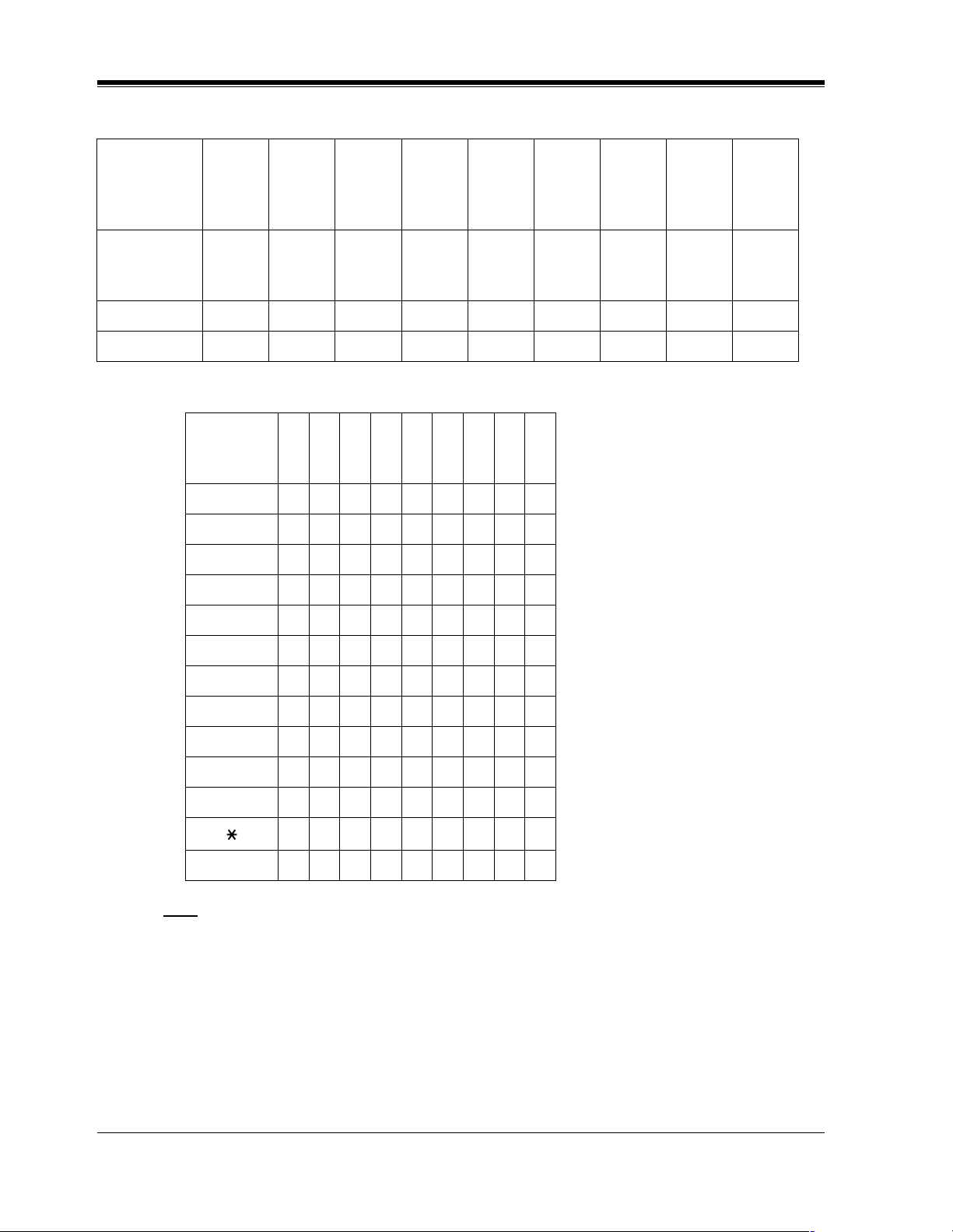
1.2 Using Proprietary Telephones
Soft Buttons and SHIFT Button on the Display DPT
Three soft buttons are provided just below the display on the display of Digital Proprietary
Telephones (DPT), KX-T7433, KX-T7436, KX-T7230 and KX-T7235. The functions of these
soft buttons vary as the programming procedures advance step by step. Those functions that
are currently assigned to the buttons are shown on the lower line of the display. (See "Viewing
the Display" in this section for more information on the display lines.)
If the SHIFT button indicator is on, two functions are available with each soft button. To
alternate between the two functions, press the SHIFT button on the right side of the display.
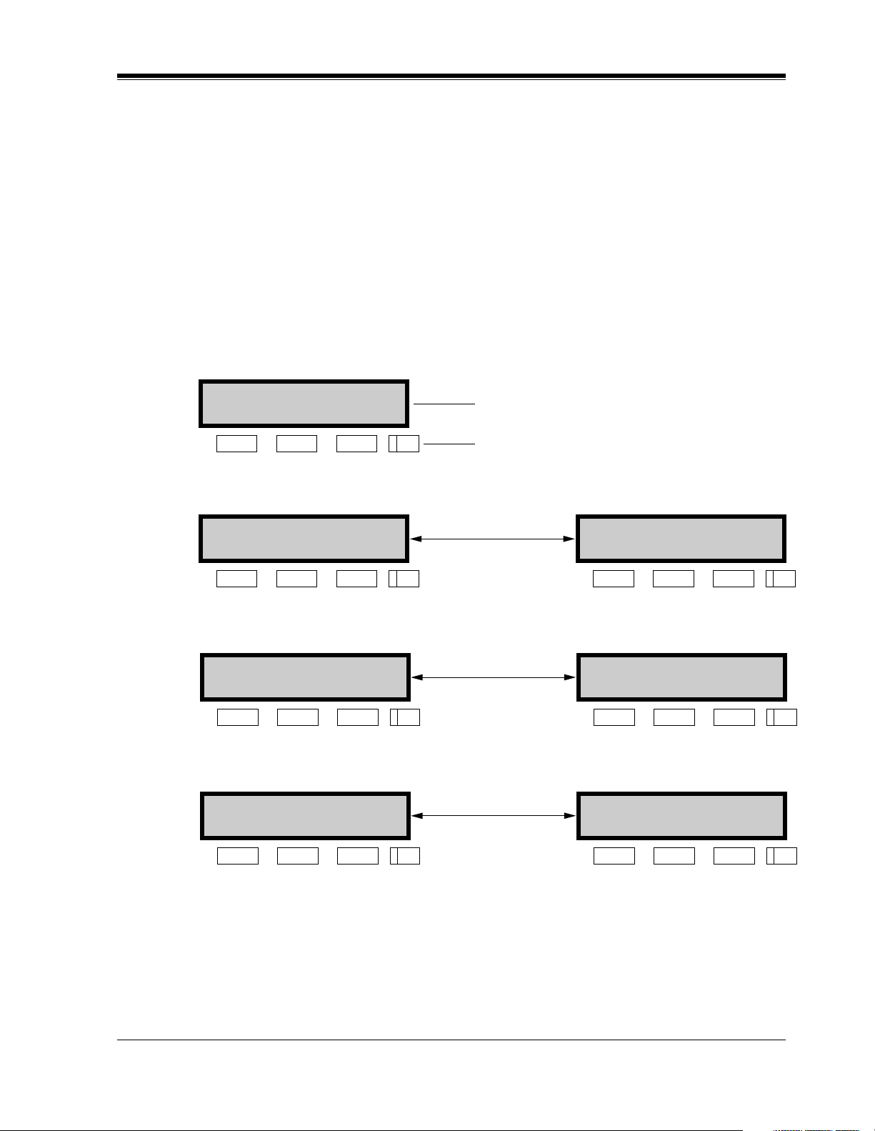
Soft button variations
Typ e 1
Example:
CLR NEXT
KX-T7230 Display
Buttons
General Programming Instructions
Soft 1 Soft 2 Soft 3 SHIFT
Typ e 2
Press SHIFT
to alternate
SKP+ CLR NEXT
Soft 1 Soft 2 Soft 3 SHIFT
Typ e 3
Press SHIFT
to alternate
SEL+-> NEXT SEL-<- PREV
Soft 1 Soft 2 Soft 3 SHIFT Soft 1
Typ e 4
Press SHIFT
to alternate
BAC bac
Soft 1 Soft 2 Soft 3 SHIFT Soft 1
SKP- PREV
Soft 1
Soft 2 Soft 3 SHIFT
Soft 2 Soft 3 SHIFT
Soft 2 Soft 3 SHIFT
Programming Guide 11
Page 12
General Programming Instructions
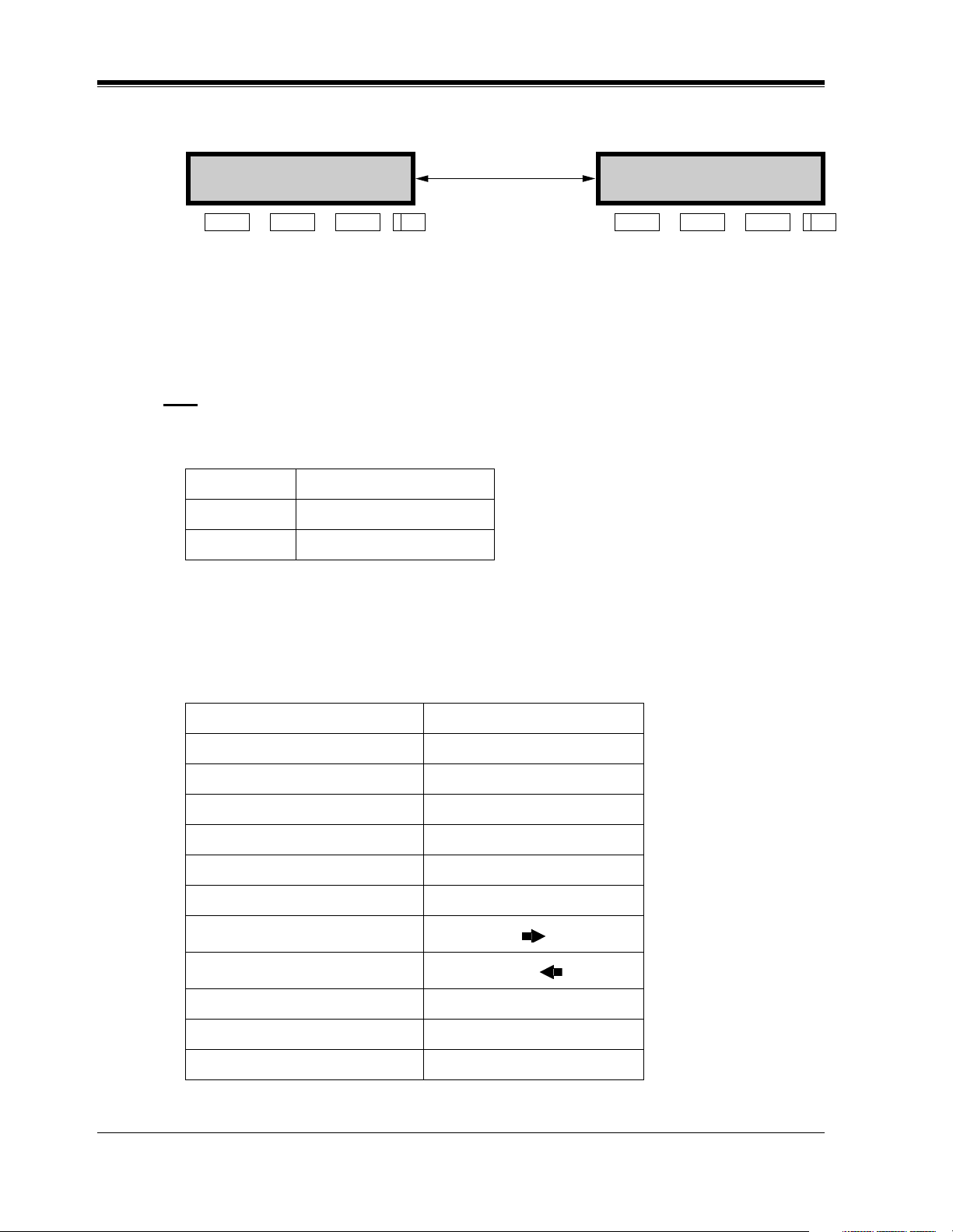
Type 5
SKP+ SEL NEXT
Press SHIFT
to alternate
SKP- CLR PREV
Soft 1 Soft 2 Soft 3 SHIFT
You can use either the soft buttons or the overlay buttons. (For overlay buttons, refer to "Using
the Overlay" below.)
Throughout programming you will see instructions such as "Press PREV". If you use soft
buttons, this means press SHIFT, release SHIFT and then press Soft 3. The (PREV) function
is performed.
Note
If you use soft buttons and if programming instructions tell you to press the following buttons,
you may press soft buttons shown below.
Instructions Soft button
SELECT SEL+,SEL-,or SEL
CLEAR CLR
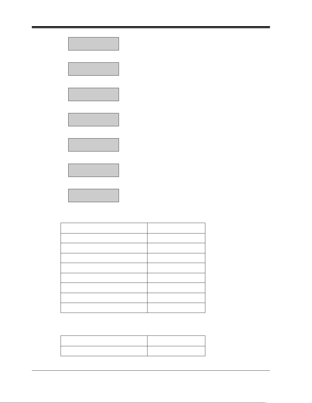
Using the Overlay
A programming overlay is packed with the telephone at the factory. This overlay should be
used at all times while in programming mode since the functions of the telephone keys change
while in programming mode as follows: (The original functions are in parentheses.)
Soft 1
Soft 2 Soft 3 SHIFT
During Normal Operation During Programming
(PAUSE) PAUSE / PROGRAM
(SP-PHONE) NEXT
(REDIAL) PREV (PREVIOUS)
(AUTO ANSWER / MUTE) SELECT
(FLASH) FLASH
(TRANSFER) CLEAR
(FWD / DND)
(CONF)
(INTERCOM) SECRET
(AUTO DIAL / STORE) STORE
(HOLD) END
— /
12 Programming Guide
Page 13
General Programming Instructions
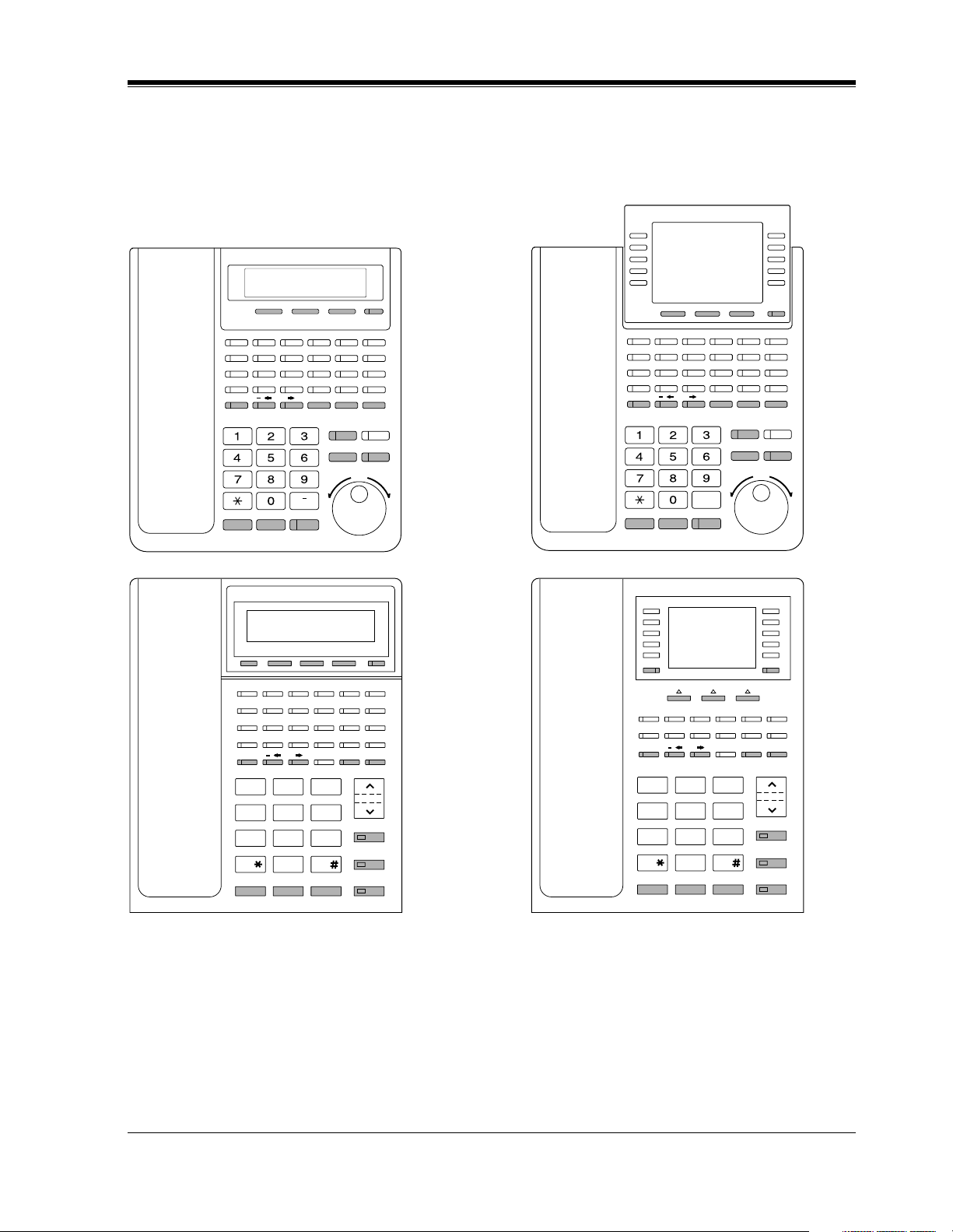
Location of Controls with the Overlay
The pictures below show the functions of the buttons of the KX-T7433, KX-T7436, KX-T7230
and KX-T7235 while in programming mode. KX-T7431 is the same as KX-T7433 except for
the Soft and SHIFT buttons.
KX-T7433
KX-T7230
SECRET
PQRS
PROGRAM SHIFTSoft-1 Soft-2 Soft-3
PROGRAM CLEAR
ABC
DEF
JKL MNOGHI
TUV WXYZ
OPER
ENDPREV NEXT
SHIFTSoft-1 Soft-2 Soft-3
PAUSE
STORE
FLASH SELECT
SELECT / VOLUME
KX-T7436
KX-T7235
SECRET
ABC DEF
JKL MNOGHI
TUV WXYZ
PQRS
OPER
ENDPREV NEXT
PROGRAM SHIFT
Soft 1 Soft 2 Soft 3
PAUSE
PROGRAM CLEAR
STORE
FLASH SELECT
SELECT / VOLUME
SHIFTSoft-1 Soft-2 Soft-3
SECRET PAUSE CLEAR
ABC
DEF
2
JKL
MNO
5
TUV
WXY
8
OPER
0
FLASHPREV END
3
VOLUME
6
STORE
9
SELECT
NEXT
PRS
1
GHI
4
7
SECRET PAUSE CLEAR
ABC
DEF
2
JKL
MNO
5
TUV
WXY
8
OPER
0
FLASHPREV END
3
VOLUME
6
STORE
9
SELECT
NEXT
GHI
PRS
1
4
7
Programming Guide 13
Page 14
General Programming Instructions
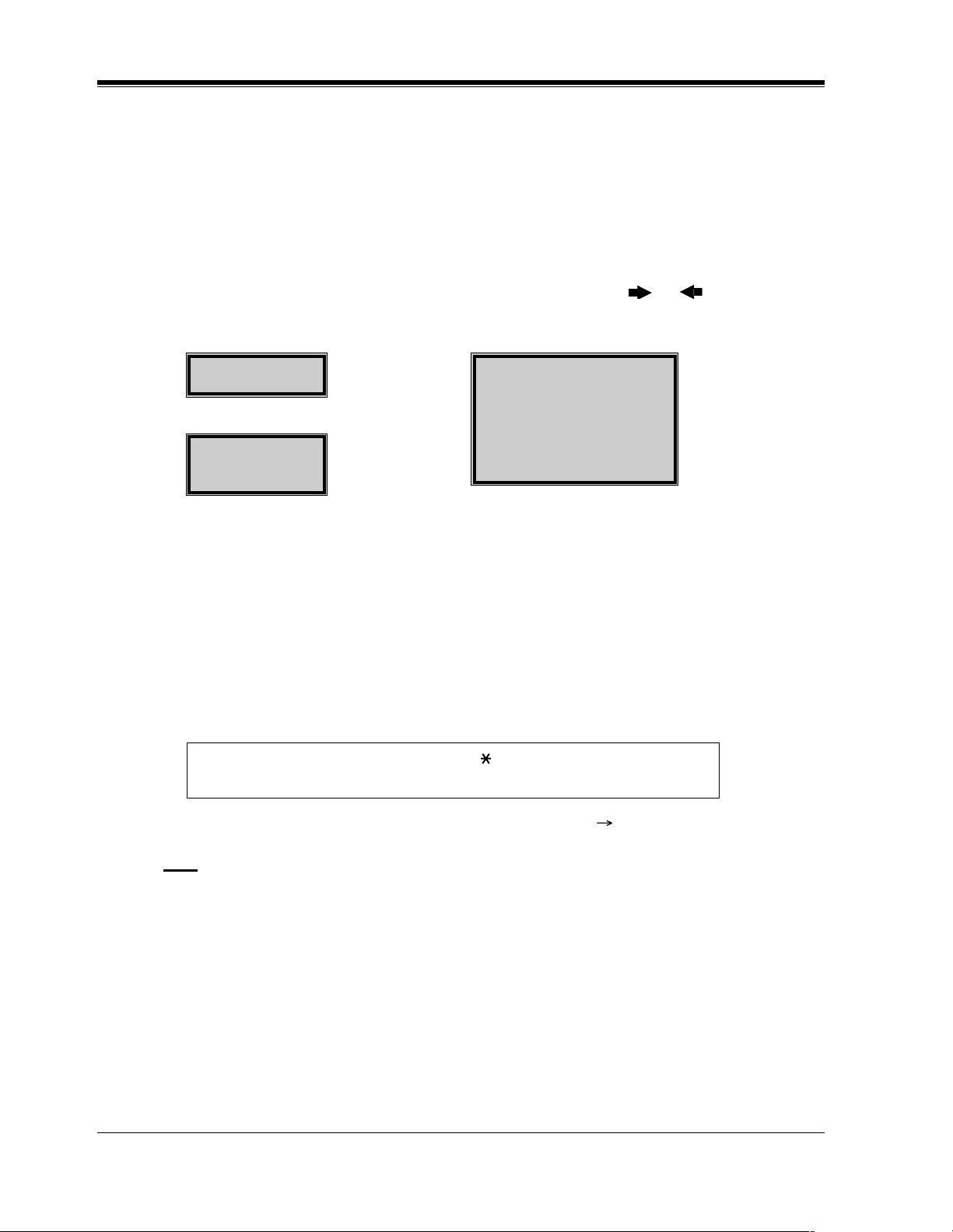
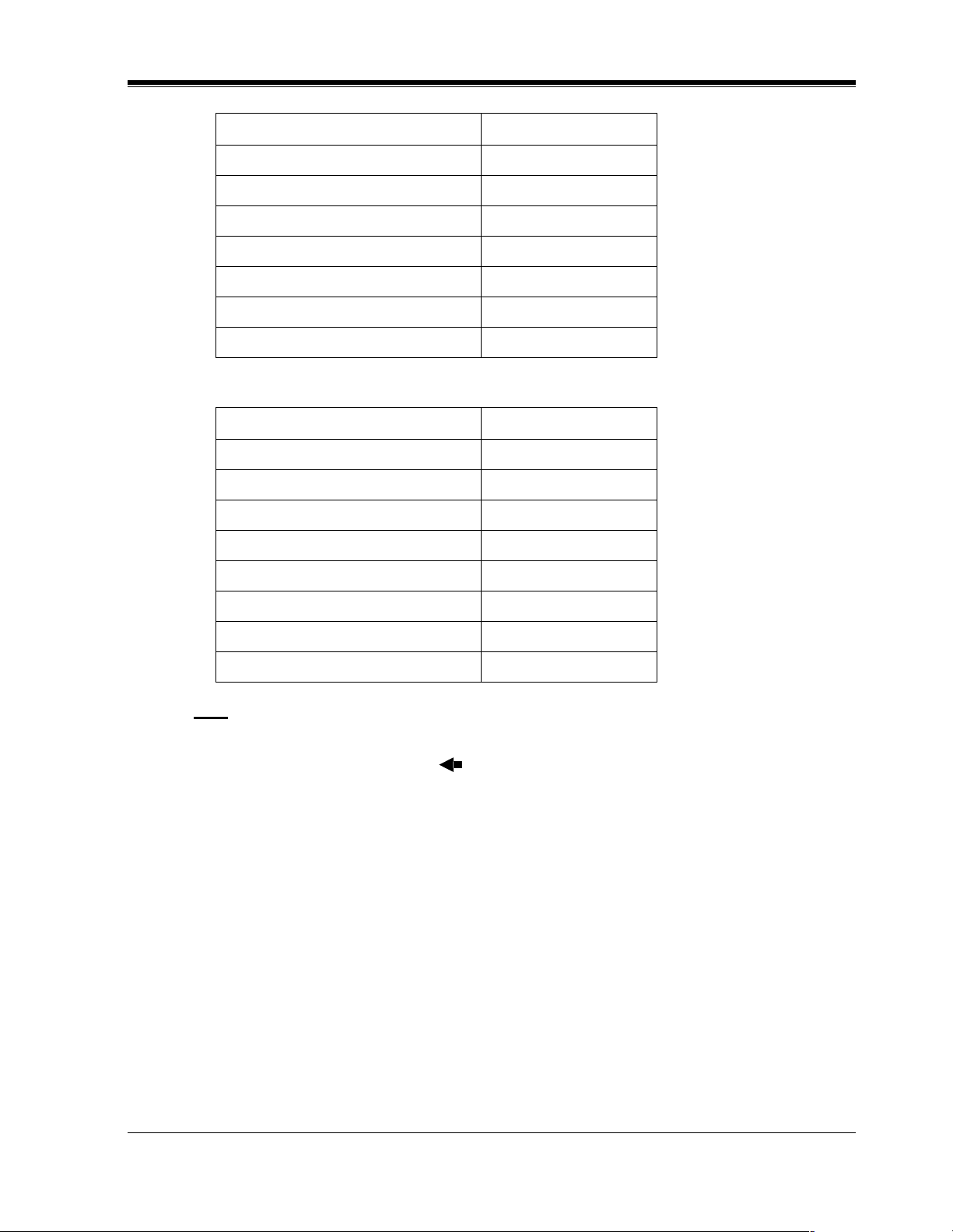
Viewing the Display
The display gives you helpful information, such as what you should do now, what you have
done, etc.
The KX-T7433, KX-T7436, KX-T7230 and the KX-T7235 utilize two information lines for
programming. The upper line is called the Message Line and the lower one is called the
Function Line.
The Message Line (upper) shows you what you should do or what you should select. It also
allows you to confirm what you have just entered. The display capacity is 16 digits. If your
entry exceeds the capacity, you can shift the display by pressing or button.
The Function Line (lower) shows the current function of the soft buttons. These functions
change with the programming procedures.
SYS-PGM NO? →
CLR NEXT
KX-T7230 Display
SYS-PGM NO? →
CLR NEXT
KX-T7433 Display KX-T7436 / KX-T7235 Display
← Message Line
← Function Line
← Message Line
← Function Line
Before entering the programming mode
Before entering programming mode, confirm that:
• Your telephone is on-hook.
• No calls are on hold at your telephone.
Entering the programming mode
Press PROGRAM (or PAUSE) + + # and enter your System
Password (default=1234).
SYS-PGM NO? →
CLR NEXT
← Message Line
← Function Line
• The display shows the Initial Message: SYS-PGM NO?
Note
• If your telephone set does not have a PROGRAM button, substitute it with the PAUSE
button.
• If nothing is entered in five seconds after the PROGRAM (or PAUSE ) button is pressed,
it is canceled.
• The System Password entered is not shown on the display. The System Password can be
changed by System Programming. Refer to Section [107] System Password.
• During the programming mode, your extension is treated as a busy extension.
• Only one proprietary telephone can be in programming mode at any one time.
14 Programming Guide
Page 15

1.3 Programming Methods
Advancing to the next stage
When "SYS-PGM NO? " is displayed, you can select one of the following:
• To go to program [000], press the NEXT button.
• To go to another program, enter the 3-digit program address.
Rotation of jack number
Each jack of the Digital Super Hybrid System supports the connection of a digital proprietary
telephone and a single line device with different extension numbers (eXtra Device Port: XDP
function). To program this function it is necessary to assign two parts for each jack. The first
part of jack one is 01-1. The second part of jack one is 01-2. The first part of jack two is 02-1
and so on. The NEXT and PREV buttons can be used to move from jack to jack as required
in programs [003], [004] and [601] through [610].
Example
General Programming Instructions
NEXT
#01-1
PREV
Note
The first part of a jack is for a DPT of a XDP-assigned jack. The second part is for a single line
device. Program [600] "EXtra Device Port" assigns which jacks are XDP.
Storing your data
Press STORE to store your data.
•The STORE indicator lights red and a confirmation tone is emitted.
* Confirmation tone (one beep)
After pressing STORE, you will hear a beep. This informs you that storage is completed.
* Alarm tone (three beeps)
If you hear this alarm, your entry is not valid.
#01-2
NEXT
PREV
NEXT
#02-1 #02-2......
PREV
Making another selection within the same program address
• To make the next higher selection, press NEXT.
• To make the previous selection, press PREV.
• To make a specific selection, press SELECT and then enter the number.
Programming Guide 15
Page 16

General Programming Instructions
Going to another program address
After pressing STORE, you can go to another program with either of the following two
methods:
a) To go to the next larger program address:
Press Soft 1 (SKP+) or VOLUME (DOWN).
To go to the next smaller program address:
Press SHIFT + Soft 1 (SKP—) or VOLUME (UP).
b) To go to a specific program address:
Press END, then enter the Program Address.
Method (1) is useful when you want to perform a series of programs consecutively. For
example, to change the programming in addresses [000] to [008], use this method. You can
move from [000] to [001], from [001] to [002], and so on by pressing the SKP+ or VOLUME
. You can move in reverse order from [008] to [007], etc. by pressing the SKP— or
VOLUME .
This method can also be used to move between neighboring program groups: For example,
you can move between the program addresses [008] and [100], [116] and [200], and so on.
Also, you can move between the smallest program address [000] and the largest one [991].
Method (2) is useful when you wish to jump to another program address. For example, you
have just finished with program [006] and now you want to go to program [301]. Neither SKP+
/ VOLUME nor SKP— / VOLUME is convenient in this case. So you should press END
and enter 301.
Note
The following programming instructions assume that you have already entered the
programming mode and that you will use Method (2).
Confirming the entries
You may review the stored programming without making any changes.
Going back to the operation mode
Two ways are available to go back to the operation mode:
a) Lift the handset while in programming mode.
b) When the Initial Message: SYS-PGM NO? is displayed, press the PROGRAM (or
PAUSE ) button. (To display the Initial Message, press END.)
16 Programming Guide
Page 17

1.4 Entering Characters
Entering Characters
You can enter characters to store names or messages in the following programs by using the
dialing key pad, buttons or the Jog Dial.
[002] System Speed Dialing Name Set
[004] Extension Name Set
[008] Absent Messages
[013] ISDN Extension Name Set
[014] VM Name Set
[111] Caller ID Name Set
[139] DID Extension Name Set
[417] Outside Line Name Assignment
[726] T1 Extension Name
See the Combination Tables below.
General Programming Instructions
Combination Tables
Combination Table a
SHIFT &
Soft
Combination
Pressing
SELECT
(Times)
Keys
11QqZz!?
2 2AaBbCc
33DdEeFf
4 4GgHh I i
55JjKkLl
66MmNnOo
77PpQqRrSs
012345678
S1 SHIFT
+ S1
S2 SHIFT
+ S2
S3 SHIFT
+ S3
SHIFT
+
SHIFT
+ S1
SHIFT
SHIFT
+
+ S2
88TtUuVv
99WwXxYyZz
00 .,':;
* / +- =<>
Programming Guide 17
Page 18
General Programming Instructions
Combination Table a
SHIFT &
Soft
S1 SHIFT
+ S1
S2 SHIFT
+ S2
S3 SHIFT
Combination
Pressing
012345678
SELECT
(Times)
Keys
##$%&@()
Combination Table b
Rotating
012345678
Jog Dial
(Pulses)
Keys
11QqRrSsTt
22AaBbCcDd
3 3DdEe F fGg
+ S3
SHIFT
+
SHIFT
+ S1
SHIFT
+
SHIFT
+ S2
44GgHhIiJj
55JjKkLlMm
6 6MmNnOo Pp
77PpQqRrSs
8 8T t UuVvWw
9 9WwXxYyZ z
00!?.,':;
*/+-=<>#$
##$%&@()Aa
Note
• The alphabetical characters correspond to the letters shown on the twelve dialing keys on
the proprietary telephone. (except symbols)
• In Combination Table a:
If your telephone is a KX-T7431, do not use the provided SELECT button. Use the AUTO
ANSWER / MUTE button which becomes the SELECT button when using the overlay.
• In Combination Table b:
If you keep rotating the Jog Dial, all of the characters in the table will be displayed.
18 Programming Guide
Page 19

General Programming Instructions
Please see the following example which shows how to select a desired character.
For example, to select the letter "M":
Select either of the following three methods:
1. Using the SHIFT and Soft buttons
(for KX-T7433 / KX-T7436 / KX-T7230 / KX-T7235 only)
* See Combination Table a.
a) Press 6. ("M" belongs to "6".)
• The Function Line shows: M N O
b) Press the Soft 1 (M) button.
(Press SHIFT to display the lower case of the above letters.)
2. Using the SELECT button
* See Combination Table a.
a) Press 6. ("M" belongs to "6".)
b) Press the SELECT button once.
• Pressing the SELECT button an appropriate number of times gives you the desired
letter. Pressing SELECT twice gives the letter "m", pressing three times gives "N",
and so on.
3. Using the Jog Dial
(for KX-T7431 / KX-T7433 / KX-T7436 only)
* See Combination Table b.
a) Press 6. ("M" belongs to "6".)
b) Rotate the Jog Dial one pulse.
• Rotating the Jog Dial an appropriate number of pulses gives you the desired letter.
Rotating the Jog Dial two pulses gives the letter "m", rotating three pulses gives "N",
and so on.
OR
a) Press any dialing keypad.
b) Rotate the Jog Dial until the desired character appears.
• If you keep rotating the Jog Dial, all of the characters will be displayed. For example,
If you rotate the Jog Dial after pressing 2, characters will appear in the following
order: A a B b •••• Z z (space) ! ? . , ' : ; * / + — = < > # $ % & @ ( ) A a B b ••••
Example of entering characters: to enter "Mike":
Using method (1)
* See Combination Table a.
a) Enter 6
6
M N O
b) Press Soft 1 (M)
M
M N O
c) Enter 4
Programming Guide 19
Page 20
General Programming Instructions
M4
G H I
d) Press SHIFT.
M4
g h i
e) Press Soft 3 (i)
Mi
g h i
f) Enter 5
Mi5
j k l
g) Press Soft 2 (k)
Mik
j k l
h) Enter 3
Mik3
d e f
i) Press Soft 2 (e)
Mike
d e f
Using method (2)
* See Combination Table a.
The display shows:
1. Enter 6.6
2. Press SELECT.M
3. Enter 4.M4
4. Press SELECT six times. Mi
5. Enter 5.Mi5
6. Press SELECT four times. Mik
7. Enter 3.Mik3
8. Press SELECT four times. Mike
Using method (3)
* See Combination Table b.
The display shows:
1. Enter 6.6
20 Programming Guide
Page 21
General Programming Instructions
The display shows:
2. Rotate Jog Dial one pulse. M
3. Enter 4.M4
4. Rotate Jog Dial six pulse. Mi
5. Enter 5.Mi5
6. Rotate Jog Dial four pulses. Mik
7. Enter 3.Mik3
8. Rotate Jog Dial four pulses. Mike
OR
The display shows:
1. Enter 2.2
2. Rotate Jog Dial until "M" appears. M
3. Enter 2.M2
4. Rotate Jog Dial until "i" appears. Mi
5. Enter 2.Mi2
6. Rotate Jog Dial until "k" appears. Mik
7. Enter 2.Mik2
8. Rotate Jog Dial until "e" appears. Mike
Note
• To erase all the letters, press CLEAR.
• To erase the last letter, press .
Programming Guide 21
Page 22

General Programming Instructions
1.5 User Programming Mode
User Programming Mode
Some programming items are accessible by any display proprietary telephone user in the
system.
The programming items are listed below:
[000] Date and Time Set
[001] System Speed Dialing Number Set
[002] System Speed Dialing Name Set
[003] Extension Number Set
[004] Extension Name Set
[005] Flexible CO Button Assignment
[006] Operator / Manager Extension Assignment
[007] DSS Console Port and Paired Telephone Assignment
[008] Absent Message
[009] Quick Dial Number Set
[012] ISDN Extension Number Set
[013] ISDN Extension Name Set
[014] VM Name Set
[017] DISA User Codes
Entering the user programming mode
You can access these programs by entering the User Programming Mode as follows:
Before entering the mode, confirm that:
• Your telephone is on-hook.
• No calls are on hold at your telephone
Press PROGRAM (or PAUSE) + + and enter the User
Password (default: 1234)
After entering the mode, perform the same programming steps as the system programming
steps in each program address.
Note
• If your telephone set does not have a PROGRAM button, substitute it with the PAUSE
button.
• If nothing is entered in five seconds after the PROGRAM (or PAUSE) button is pressed,
it is canceled.
• The User Password is not shown on the display. The password can be changed by system
programming. Refer to Section [120] User Password.
• During the programming mode, your extension is treated as a busy extension.
• Only one proprietary telephone can be in programming mode at any one time.
22 Programming Guide
Page 23

1.6 Programming Example
Programming Example
The following programming instructions assume that you have already entered the
programming mode and that you will employ method (2) of "Going to another program
address" in Section 1.2 Using Proprietary Telephones.
Example: Program [001] System Speed Dialing Number Set.
Sample of Description Explanation
(1)
[001]
Description
Selection
Default
Programming
System Speed Dialing Number Set
Used to program the System Speed Dial numbers.
These numbers are available to all extension
users. There are 500 numbers available from 000
to 499.
(4)
• Speed dial number: 000 through 499
• Telephone number: 24 digits (max.)
(5)
All speed dial numbers – Not stored
1. Enter 001.
2. Press NEXT.
3. Enter a speed dial number.
4. Enter a telephone number.
5. Press STORE.
(3)
(6)
(7)
Display:
Display: SPD Code?→
To enter speed dial number 000,
you can also press NEXT.
Display example: 000:Not Stored
To delete the current entry, press
CLEAR.
To change the current entry, press
CLEAR and the new number.
001 SYS SPD DIAL
(9)
(13)
(14)
(8)
(10)
(12)
(2)
(1) Program address: This address is printed at the top
(2) Program title.
(3) Provides a more detailed description of the
(4) Shows you choices that you can assign.
(5) Shows you the default (factory setting).
(6) Shows you programming procedures step by step.
(7) Enter the program address.
(8)
(9)
(10) The message line advises you to enter a speed dial
(11) If the telephone number has already been stored,
(11)
(12) Enter the telephone number that you want to store.
(13) Pressing CLEAR erases the whole entry.
(14) Your entry is now stored.
General Programming Instructions
of every page to allow you to quickly find the
desired program.
program.
• While programming, use the overlay.
• Before starting to program, enter the
programming mode. (See “Entering the
programming mode” in section 1.2 “Using
Proprietary Telephones”).
The display shows the program title. If your
telephone has soft buttons, the lower line shows
the functions that are currently assigned to them.
Press either Soft 3 (NEXT)shown on the display
or the NEXT shown on the overlay.
number.
the number is displayed.
Your entry is displayed as you enter the digits.
The indicator lights red and a confirmation tone
lets you know that storage is complete.
Programming Guide 23
Page 24
General Programming Instructions
Sample of Description Explanation
6. To program another speed dial
number, press NEXT or
PREV, or SELECT and the
desired speed dial number
7. Repeat steps 4 through 6.
8. Press END.
Conditions
Features Guide References
(18)
• Each speed dial number has a
maximum of 24 digits. The valid
characters are 0 through 9, the and
# keys, and the FLASH or FLASH /
RCL, PAUSE, SECRET and –
(hyphen) buttons.
Special Display Features – Call Directory
System Speed Dialing
(17)
(19)
.
(16)
(15)
(15) Select the best way for you to store another speed
dial number. Pressing the NEXT / PREV allows
you to select the next higher / lower speed dial
number. You can also keep pressing them until the
desired one is displayed. If you press SELECT
and the desired speed dial number, the selected
code is displayed.
(16) You can continue to program another entry.
(17) After you have stored all your entries, finish this
program by pressing END. After pressing END
you can go to any program address you desire.
You can return to the Initial Message mode any
time by pressing END.
To go to the next lager program address, do not
press END but press Soft 1 (SKP+) or
VOLUME
.
To go to the next smaller program address, do not
press END but press SHIFT + Soft 1 (SKP-) or
VOLUME
.
(18) Tells you what you should notice or consider when
doing the programming.
(19) Lists all of the features related to the
programming. These features are described in
Section 3.
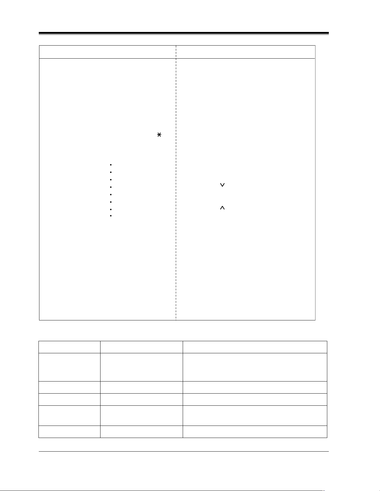
Programming Structure
Program Address Programming Group Description
[0XX] Manager Programming These programs may be accessed by the system
manager of the customer to meet frequent changes
requested by the customer.
[1XX] System Programming Entire system programming.
[2XX] Timer Programming Flexible system timer setting.
[3XX] TRS / ARS Programming Assignment of Toll Restriction and Automatic
Route Selection (ARS).
[4XX] Outside Line Programming Setting of outside line and outside line group values.
24 Programming Guide
Page 25

General Programming Instructions
Programming Structure
Program Address Programming Group Description
[5XX] COS Programming Setting of Class of Service (COS).
[6XX] Extension Programming Setting of extension values.
[7XX] T1 Programming Setting of T1 Line.
[8XX] Resource Programming Assignment of customer-supplied peripherals
connected to the system.
[9XX] Option Programming Used to answer the user's requirements or troubles,
if needed.
Programming Guide 25
Page 26

General Programming Instructions
26 Programming Guide
Page 27

General Programming
Section 2
General Programming
Programming Guide 27
Page 28

General Programming
2.1 Manager Programming
[000] Date and Time Set
NOTICE
It is assumed that you have read Section "General Programming Instructions". Soft button
usage is explained in that section, therefore no references will be made to them in the following
instructions. The soft buttons can be used in place of the overlay keys at any time.
Description
Sets the current date and time. A 12 hour format or 24 hour format can be selected.
Selection
•Year: 00 through 99
• Month: Jan. through Dec.
•Day: 1 through 31
• Day of the week: SUN / MON / TUE / WED / THU / FRI / SAT
• Hour: 1 through 12
•Minute: 00 through 59
• AM / PM
• Hour format: 12 or 24
Default
'93 Jan. 1 FRI 12:00 AM 12
Programming
1. Enter 000.
Display: 000 DATE / TIME
2. Press NEXT.
Display example: '93 Jan. 1 FRI
3. Enter the year.
To change the current entry, press CLEAR and enter the new year.
4. Press .
5. Keep pressing SELECT until the desired month is displayed.
6. Press .
7. Enter the day.
To change the current entry, press CLEAR and enter the new day.
28 Programming Guide
Page 29

8. Press .
9. Keep pressing SELECT until the desired day of the week is displayed.
10.Press STORE.
11.Press NEXT.
Display example: 12:00 PM 24
12.Enter the hour.
To change the current entry, press CLEAR and enter the new hour.
13.Press .
14.Enter the minute.
To change the current entry, press CLEAR and enter the new minute.
15.Press .
16.Press SELECT for AM or PM.
17.Press .
18.Press SELECT for 12 or 24 (hour format).
19.Press STORE.
20.Press END.
General Programming
Conditions
• After changing an entry, you can press STORE. You do not have to perform the rest of the
steps.
• To return to a previous field, press in steps 4 through 9 and steps 13 through 18.
• If you hear an alarm after pressing STORE, check that the date is valid.
• The clock starts immediately after the STORE button is pressed.
• You cannot leave an entry empty.
• Program [990] System Additional Information, Area 05 - Bit 1 is used to enable the
automatic time adjustment by Caller ID information once a day.
Features Guide References
Display, in Idle
Programming Guide 29
Page 30

General Programming
[001] System Speed Dialing Number Set
Description
Used to program the System Speed Dial numbers. These numbers are available to all extension
users. There are 500 numbers available from 000 to 499.
Selection
• Speed dial number: 000 through 499
• Telephone number: 24 digits (max.)
Default
All speed dial numbers - Not stored
Programming
1. Enter 001.
2. Press NEXT.
3. Enter a speed dial number.
4. Enter a telephone number.
5. Press STORE.
6. To program another speed dial number, press NEXT or PREV, or SELECT and the desired
speed dial number.
7. Repeat steps 4 through 6.
8. Press END.
Conditions
• Each speed dial number has a maximum of 24 digits. The valid characters are 0 through 9,
the and # keys, and the FLASH or FLASH / RCL , PAUSE, SECRET and — (hyphen)
buttons.
-To store a flash signal, press FLASH or FLASH/RCL.
Note:
The stored flash will only be effective during a call. (Refer to Section "External Feature
Access" in the Features Guide.)
-To store a hyphen, press the "—" button.
Display: 001 SYS SPD DIAL
Display: SPD Code?
To enter speed dial number 000, you can also press NEXT.
Display example: 000:Not Stored
To delete the current entry, press CLEAR.
To change the current entry, press CLEAR and enter the new number.
30 Programming Guide
Page 31

General Programming
-To store a pause, press PAUSE. (Refer to Section "Pause Insertion, Automatic" in the
Features Guide.)
-To store a feature number to convert pulse signals to DTMF (Dual Tone Multi-Frequency)
signals, press the and # keys. (Refer to Section "Pulse to Tone Conversion" in the
Features Guide.)
-To prevent displaying of all or part of the number, press SECRET before and after the
secret number, or your entry will not be stored. (Refer to Section "Secret Dialing" in the
Features Guide.)
• If you are storing an external number, include the line access code (default: 9, 81 through
88) before the number. When dialing, a pause is automatically inserted after the code.
• If you are storing an account code, enter the account code before the line access code. (Refer
to Section "Account Code Entry" in the Features Guide.)
• A number consisting of 25 digits or more can be stored by storing it in two speed dial
numbers. The line access code should be stored in the first speed dial number.
• To access another speed dial number in steps 3 through 6, press SELECT and start with
step 3.
• To display parts of the number which have scrolled off the display, press or .
• Program [002] System Speed Dialing Name Set is used to name the speed dial numbers.
Features Guide References
Special Display Features — Call Directory
System Speed Dialing
Programming Guide 31
Page 32

General Programming
[002] System Speed Dialing Name Set
Description
Assigns names to the system speed dial numbers assigned in program [001] System Speed
Dialing Number Set. KX-T7235, KX-T7431, KX-T7433, and KX-T7436 telephones can show
the stored name during System Speed Dialing.
Selection
• Speed dial number: 000 through 499
• Name: 10 characters (max.)
Default
All speed dial numbers - Not stored
Programming
1. Enter 002.
2. Press NEXT.
3. Enter a speed dial number.
4. Enter a name.
5. Press STORE.
6. To program another speed dial number, press NEXT or PREV, or SELECT and the desired
speed dial number.
7. Repeat steps 4 through 6.
8. Press END.
Conditions
Display: 002 SYS SPD NAME
Display: SPD Code?
To enter speed dial number 000, you can also press NEXT.
Display example: 000:Not Stored
For entering characters, see Section 1.4 Entering Characters.
To delete the current entry, press CLEAR.
To change the current entry, press CLEAR and enter the new name.
• Speed dial numbers are programmed in program [001] System Speed Dialing Number
Set.
• Each name has a maximum of 10 characters.
• To go to another speed dial number in steps 3 through 6, press SELECT and start with step
3.
32 Programming Guide
Page 33

Features Guide References
Special Display Features — Call Directory
General Programming
Programming Guide 33
Page 34

General Programming
[003] Extension Number Set
Description
Assigns an extension number to each extension.
Note
This programming should be performed before you connect a Panasonic Voice Processing
System (VPS) because the VPS can create mailboxes automatically based on your extension
plan (extension number set).
Selection
•Jack number:
KX-TD816 - 01 through 16 (-1 / -2)
KX-TD1232 - 01 through 64 (-1 / -2)
(-1 = first part, -2 = second part)
• Extension Number: 2 through 4 digits
Default
KX-TD816
Jack 01-1 through 16-1 = 101 through 116;
Jack 01-2 through 16-2 = 201 through 216
KX-TD1232
Jack 01-1 through 64-1 = 101 through 164;
Jack 01-2 through 64-2 = 201 through 264
Programming
1. Enter 003.
Display: 003 EXT NUMBER
2. Press NEXT.
Display: Jack NO?
3. Enter a jack number.
To enter jack number 01, you can also press NEXT.
To select the second part (-2), press NEXT after entering the jack number.
Display: #01-1:EXT101
4. Enter an extension number.
To change the current entry, press CLEAR and enter the new number.
5. Press STORE.
6. To program another jack, press NEXT or PREV, or SELECT and the desired jack
number.
34 Programming Guide
Page 35

7. Repeat steps 4 through 6.
8. Press END.
Conditions
• There is a maximum of 32 extension numbers for KX-TD816, and 128 extension numbers
for KX-TD1232. Each extension number can be two, three, or four digits, consisting of 0
through 9. The and # keys cannot be used.
• For the KX-TD1232, jack numbers 01 through 32 are for the Master System and 33 through
64 are for the Slave, if available.
• An extension number is invalid if the first or second digits do not match with the program
"[100] Flexible Numbering, (01) - (16) 1st through 16th hundred extension blocks"
setting. If one digit is assigned as the leading digit, some extensions have two digits and
some have three digits. If two digits are assigned, some have three digits and some have
four digits.
• Two extension numbers can be assigned per jack. If eXtra Device Port (XDP) is disabled
for the jack in program [600] EXtra Device Port, the extension number of the second part
(XX-2) is not available. (XX=jack number)
• For an explanation of jack numbering, see "Rotation of jack number" in Section
1.3 Programming Methods.
• A double entry or incompatible entry is invalid including the program [012] ISDN
Extension Number Set, [118] Voice Mail Extension Number Assignment,
[124] Phantom Extension Number Assignment and [813] Floating Number
Assignment. Valid entry examples are: 10 and 11; 10 and 110. Invalid entry examples are:
10 and 106; 210 and 21.
• Program [004] Extension Name Set is used to name the extension numbers.
General Programming
Features Guide References
Display, Call Information
EXtra Device Port (XDP)
Flexible Numbering
Intercom Calling
Special Display Features — Call Directory
Programming Guide 35
Page 36

General Programming
[004] Extension Name Set
Description
Assigns names to the extension numbers programmed in program [003] Extension Number
Set.
Selection
•Jack number:
KX-TD816 — 01 through 16 (-1 / -2)
KX-TD1232 — 01 through 64 (-1 / -2)
(-1 = first part, -2 = second part)
• Name:
10 characters (max.)
Default
All jacks — Not stored
Programming
1. Enter 004.
Display: 004 EXT NAME SET
2. Press NEXT.
Display: Jack NO?
3. Enter a jack number.
To enter jack number 01, you can also press NEXT.
To select the second part (-2), press NEXT after entering a jack number.
Display: #01-1:Not Stored
4. Enter a name.
For entering characters, see Section 1.4 Entering Characters.
To delete the current entry, press CLEAR.
To change the current entry, press CLEAR and enter the new name.
5. Press STORE.
6. To program another jack, press NEXT or PREV, or SELECT and the desired jack
number.
7. Repeat steps 4 through 6.
8. Press END.
Conditions
• There is a maximum of 32 names for KX-TD816, and 128 names for KX-TD1232. Each
name has a maximum of 10 characters.
36 Programming Guide
Page 37

• Program [003] Extension Number Set is used to assign extension numbers.
• For the KX-TD1232, jack numbers 01 through 32 are for the Master System and 33 through
64 are for the Slave, if available.
• For an explanation of jack numbering, see "Rotation of jack number" in section
1.3 Programming Methods.
Features Guide References
Display, Call Information
Intercom Calling
Special Display Features — Call Directory
General Programming
Programming Guide 37
Page 38

General Programming
[005] Flexible CO Button Assignment
Description
Used to determine the use of the flexible CO buttons on proprietary telephones from a
centralized telephone.
Selection
•Jack number:
KX-TD816 — 01 through 16
KX-TD1232 — 01 through 64
• Button Code (plus parameter, if required):
Button Code Parameter
0 (Single-CO) KX-TD816 - 01 through 08 (Outside line number)
KX-TD1232 - 01 through 48 (Outside line number)
1 (DSS) 2 to 4 digits (Extension number)
2 (One-Touch) 16 digits max. (Telephone number)
3 (Message Waiting) None
3 (Another Extension Message
Waiting / Phantom Extension
Message Waiting)
4 (FWD / DND) None
5 (Save) None
6 (Account) None
70 (Conference) None
71 (Log-In / Log-Out) None
72 (Phantom) 2 to 4 digits (Phantom extension number)
73 (Night) None
8 (Voice Mail Transfer) 2 to 4 digits (Voice Mail Extension number)
90 (Two-Way Record)* 2 to 4 digits (Voice Mail Extension number)
91 (Two-Way Transfer)* 2 to 4 digits (Voice Mail Extension number)
92 (Live Call Screening)* None
2 to 4 digits (Another / Phantom Extension number)
93 (Live Call Screening Cancel)* None
(Loop-CO)
# (Group-CO) 1 through 8 (Outside line group number)
CO (ringer frequency) 1 through 8 (ring tone type number)
None
38 Programming Guide
Page 39

General Programming
* Available when the Digital Super Hybrid System is connected to a Digital Proprietary Telephone
capable Panasonic Voice Processing System (one that supports digital proprietary telephone
integration; e.g., KX-TVS100).
Default
[KX-TD816]
All jacks — CO buttons 1 through 8 = Single-CO 01 through 08; Ring tone type 2
Others = Not stored
[KX-TD1232]
All jacks — CO buttons 1 through 48 = Single-CO 01 through 48; Ring tone type 2
Programming
1. Enter 005.
Display: 005 FLEXIBLE CO
2. Press NEXT.
Display: Jack NO?
3. Enter a jack number.
To enter jack number 01, you can also press NEXT.
Display: PT—PGM Mode
4. Press the CO button which is changed to another button.
The display shows the contents pre-assigned to the button.
Display example: CO-01
5. Enter a button code (plus parameter, if required).
To change the parameter, press CLEAR and enter the new parameter.
6. Press STORE.
7. To program another CO button of the same jack, repeat steps 4 through 6.
To program another jack, press SELECT and repeat steps 3 through 6.
8. Press END.
Canceling
1. Perform the same procedures as steps 1 through 4 above.
2. Enter 2.
3. Press STORE.
4. Press END.
Conditions
• A centralized telephone is a telephone connected to jack 01 or a jack programmed as a
manager extension in program [006] Operator / Manager Extension Assignment.
Programming Guide 39
Page 40

General Programming
• For the KX-TD1232, jack numbers 01 through 32 are for the Master System and 33 through
64 are for the Slave, if available. Jack numbers in the out-of-service system are
unacceptable.
• The number of the CO buttons available depends on the telephone type. (Refer to Buttons
on Proprietary Telephones in the Feature Guide.) To program 24 CO buttons, use the
proprietary telephone, KX-T7425, KX-T7433, KX-T7436 or KX-T7230.
• If you press the same CO button again in step 5, you can select a desired ringer frequency
for the CO button from eight types of ring tones. When you enter the tone type number (1
through 8), you will hear the selected tone type until STORE is pressed. This selection is
possible only for the CO buttons that have been assigned to Single-CO, Group-CO, or
Loop-CO.
Features Guide References
Button, Flexible
Buttons on Proprietary Telephones
40 Programming Guide
Page 41

[006] Operator / Manager Extension Assignment
Description
Assigns the jack number for a manager and/or operators. The manager extension can perform
System Programming and manager services. The operators have the ability to perform operator
services.
Selection
• OPE-1 (operator 1) / OPE-2 (operator 2) /MNGER (manager)
• Jack number:
KX-TD816 — 01 through 16
KX-TD1232 — 01 through 64
Default
Operator 1 — Jack 01;
Operator 2 and Manager — Not stored
General Programming
Programming
1. Enter006.
Display: 006 OP-1, 2, MGR
2. Press NEXT to program operator 1.
Display: OPE-1:Jack01
To program another item, you can also keep pressing NEXT or PREV until the desired
one is displayed.
3. Enter a jack number.
To assign no operator or manager, press CLEAR.
To change the current entry, press CLEAR and enter the new jack number.
4. Press STORE.
5. To program another item, press NEXT or PREV.
6. Repeat steps 3 through 5.
7. Press END.
Conditions
• Up to two operators and a manager can be programmed.
• For the KX-TD1232, jack numbers 01 through 32 are for the Master System and 33 through
64 are for the Slave, if available.
• The manager cannot be assigned the jack number of the DSS Console Port set in program
[007] "DSS Console Port and Paired Telephone Assignment".
Programming Guide 41
Page 42

General Programming
• If the assigned jack is in eXtra Device Port mode, the proprietary telephone jack is treated
as the manager / operator extension.
• If there is no operator or manager, press CLEAR in step 3.
Features Guide References
Manager Extension
Operator
42 Programming Guide
Page 43

General Programming
[007] DSS Console Port and Paired Telephone Assignment
Description
Assigns the jack numbers for the DSS Console and the paired extension.
Selection
• DSS Console number:
KX-TD816 — 1 through 4
KX-TD1232 — 1 through 4 (for Master), 5 through 8 (for Slave)
• Jack number for DSS Console:
KX-TD816 — 02 through 16
KX-TD1232 — 02 through 32 (for Master), 33 through 64 (for Slave)
• Jack number for paired extension:
KX-TD816 — 01 through 16
KX-TD1232 — 01 through 32 (for Master), 33 through 64 (for Slave)
Default
All DSS Consoles — Not stored
Programming
1. Enter 007.
Display: 007 DSS CONSOLE
2. Press NEXT.
Display: DSS NO?
3. Enter a DSS Console number.
To enter DSS Console number 1, you can also press NEXT.
Display example: DSS—1:# P:#
4. Enter a jack number for the console.
To delete the current entry, press CLEAR.
To change the current entry, press CLEAR and enter the new jack number.
5. Press .
6. Enter a jack number for the paired extension.
To change the current entry, press CLEAR and enter the new jack number.
Display example: DSS—1:#02 P:#03
7. Press STORE.
8. To program another DSS Console, press NEXT or PREV, or SELECT and the desired DSS
Console number.
9. Repeat steps 4 through 8.
10.Press END.
Programming Guide 43
Page 44

General Programming
Conditions
• The jack number for the Console and that for the paired extension must be entered together.
• Multiple DSS Consoles cannot be assigned to the same DSS Console jack.
• Multiple DSS Consoles can be paired with the same proprietary telephone jack.
• A DSS Console jack cannot be assigned the jack 01 and the jack number of Manager set in
program [006] Operator / Manager Extension Assignment.
• If all incoming outside calls are set to ring at the operator extension telephone in program
[407-408] DIL 1:1 Extension —— Day / Night, assigning a DSS Console to the operator
extension makes the operator’s job much easier.
• If a DSS Console - assigned jack is programmed for eXtra Device Port, a single line
telephone can be connected to the jack in parallel with the console.
• If a single line telephone is assigned as the pair extension, the paired DSS Console will not
function.
Features Guide References
DSS Console
44 Programming Guide
Page 45

[008] Absent Messages
Description
Used to program the absent messages. An absent message, if set by the station user, is
displayed on the calling extension's telephone to show the reason for the user's absence.
Selection
• Message number: 1 through 9
• Message: 16 characters (max.)
Default
1: Will Return Soon
2: Gone Home
3: At Ext %%%
4: Back at %%:%%
5: Out Until %%/%%
6: In a Meeting
7 through 9: Blank (not stored)
General Programming
Programming
1. Enter 008.
Display: 008 ABSENT MSG.
2. Press NEXT.
Display: MSG NO?
3. Enter a message number.
To enter message number 1, you can also press NEXT.
Display example: MSG1:Will Return
4. Enter the message.
For entering characters, see Section 1.4 Entering Characters.
To delete the current entry, press CLEAR.
To change the current entry, press CLEAR and enter the new message.
5. Press STORE.
6. To program another message, press NEXT or PREV, or SELECT and the desired message
number.
7. Repeat steps 4 through 6.
8. Press END.
Programming Guide 45
Page 46

General Programming
Conditions
• There is a maximum of nine messages. Messages 1 through 6 are programmed at the factory
but can be changed. Each message has a maximum of 16 characters.
• You can enter a maximum of seven "%" characters per message which can be programmed
at each user's extension. The station user can enter 0 through 9, and # for the %
characters. If the user enters digits less than the number of "%" characters, it is
recommended to fill the remaining "%" characters with "#" or " ".
• If there are 4-digit extension numbers available in your system, add one "%" to Message 3.
• To display parts of the message which have scrolled off the display, press or .
Features Guide References
Absent Message Capability
46 Programming Guide
Page 47

[009] Quick Dial Number Set
Description
Stores up to eight quick dial numbers.
Selection
• Location number: 1 through 8
• Desired number: 16 digits (max.)
Default
All location numbers — Not stored
Programming
1. Enter 009.
Display: 009 QUICK DIAL
2. Press NEXT.
Display: Location NO?
3. Enter a location number.
To enter location number 1, you can also press NEXT.
Display example: 1:Not Stored
4. Enter a desired number.
To delete the current entry, press CLEAR.
To change the current entry, press CLEAR and enter the new number.
5. Press STORE.
6. To program another location, press NEXT or PREV, or SELECT and the desired location
number.
7. Repeat steps 4 through 6.
8. Press END.
General Programming
Conditions
• A maximum of sixteen digits, consisting of 0 through 9, can be assigned to a quick dial
number.
• Before programming, assign a feature number for each location first in program
[100] Flexible Numbering.
Features Guide References
Quick Dialing
Programming Guide 47
Page 48

General Programming
[012] ISDN Extension Number Set
Description
Assigns an extension number to each port which is connected to the ISDN unit.
Selection
•Port number:
KX-TD816 — 01 through 04
KX-TD1232 — 01 through 12
• Extension Number:
2 or 3 digits
Default
All ports — Not stored
Programming
1. Enter 012.
Display: 012 ISDN EXT #
2. Press NEXT.
Display: Port NO?
3. Enter a port number.
To enter a first port number, you can also press NEXT.
Display: #01:Not Stored
4. Enter an extension number.
To change the current entry, press CLEAR and the new number.
5. Press STORE.
6. To program another port, press NEXT or PREV, or SELECT and the desired port
number.
7. Repeat steps 4 through 6.
8. Press END.
Conditions
• Each extension number can be two or three digits, consisting of 0 through 9. The and #
keys cannot be used.
• A multiple directory number (MDN) is determined regarding to this assignment. A MDN
consists of the assigned extension number and an additional digit, 0 through 9.
Example: If an ISDN extension number is assigned as "3", 30 through 39 are effective as
MDN's. The extension user can call any terminal equipment on the ISDN bus individually
using MDN. Pressing "30" calls all extensions on the ISDN bus simultaneously.
48 Programming Guide
Page 49

• Port numbers 01 through 06 are for the Master System, and 07 through 12 are for the Slave,
if available.
• An extension number is invalid if the first or second digit does not match with the setting
in program [100] Flexible Numbering, 1st through 16th hundred extension blocks.
• A double entry or incompatible entry cannot be made with assignment programs
[003] Extension Number Set, [118] Voice Mail Extension Number Assignment,
[124] Phantom Extension Number Assignment and [813] Floating Number
Assignment. Valid entry examples: 10 and 11; 10 and 110. Invalid entry examples: 10 and
106; 210 and 21.
• Program [013] ISDN Extension Name Set is used to give names to the extension
numbers.
Features Guide References
None
General Programming
Programming Guide 49
Page 50

General Programming
[013] ISDN Extension Name Set
Description
Assigns names to the ISDN extension numbers programmed in program [012] ISDN
Extension Number Set.
Selection
•Port number:
KX-TD816 — 01 through 04
KX-TD1232 — 01 through 12
• Name:
10 characters (max.)
Default
All ports — Not stored
Programming
1. Enter013.
Display: 013 ISDN NAME
2. Press NEXT.
Display: Port NO?
3. Enter a port number.
To enter the first port number, you can also press NEXT.
Display: #01:Not Stored
4. Enter a name.
For entering characters, see Section 1.4 Entering Characters.
To delete the current entry, press CLEAR.
To change the current entry, press CLEAR and the new name.
5. Press STORE.
6. To program another port, press NEXT or PREV, or SELECT and the desired port
number.
7. Repeat steps 4 through 6.
8. Press END.
Conditions
• Port numbers 01 through 06 are for the Master System and 07 through 12 are for the Slave,
if available.
• The ISDN port numbers correspond to the following jack numbers.
50 Programming Guide
Page 51

General Programming
KX-TD816 KX-TD1232
ISDN Port No. KX-
Master Slave
1 7 - Jack 1 Jack 1 - - Jack 1
2 8 - Jack 2 Jack 2 - - Jack 2
3 9 Jack 1 Jack 3 Jack 3 - Jack 1 Jack 3
4 10 Jack 2 Jack 4 Jack 4 - Jack 2 Jack 4
5 11 - - - Jack 1 Jack 3 Jack 5
6 12 - - - Jack 2 Jack 4 Jack 6
Features Guide References
None
TD382
KX-
TD384/
KX-
TD284
KX-
TD386
KX-
TD382
KX-
TD384/
KX-
TD284
KXTD386
Programming Guide 51
Page 52

General Programming
[014] VM Name Set
Description
Assigns a name for each voice mail port.
Selection
• Voice Mail (VM) number: KX-TD816 – 01 through 12
• Name: 10 characters (max.)
Default
All Voice Mails — V.Mailxx (xx=01 through 24)
Programming
KX-TD1232 – 01 through 24
1. Enter 014.
Display: 014 VM PORT NAME
2. Press NEXT.
Display: VM NO?
3. Enter a VM number.
To enter VM number 01, you can also press NEXT.
Display example: VM01:V.Mail 01
4. Enter a name.
For entering characters, see Section 1.4 Entering Characters.
To delete the current entry, press CLEAR.
To change the current entry, press CLEAR and enter the new name.
Display example: VM01:Voice No.1
5. Press STORE.
6. To program another voice mail port, press NEXT or PREV, or SELECT and the desired
voice mail number.
7. Repeat steps 4 through 6.
8. Press END.
Conditions
None
Features Guide References
Voice Mail Integration
52 Programming Guide
Page 53

[017] DISA User Codes
Description
Assigns the Direct Inward System Access (DISA) User Codes and a Class of Service (COS) to
each code. The COS of the code determines the toll restriction level of the DISA caller.
This program is available for the KX-TD1232 only.
Note
Warning for the Direct Inward System Access Users
When you enable the Outside – Outside Line Call feature of Direct Inward System Access
(DISA) function, if a third party discovers the password (a DISA User Code) of the system,
you have a risk that they will make illegal phone calls using your telephone line, and the cost
may be charged to your account.
In order to avoid this problem, we strongly recommend the following points:
1. Carefully maintain the secrecy of the password.
2. Specify a complicated password as long and random as you can make it.
3. Change the password frequently.
General Programming
Selection
• DISA user code number: 01 through 32
• DISA user code: 4 through 10 digits
• COS number: 1 through 8
Default
Code 01=Blank — COS 8
Code 02=Blank — COS 8
:
Code 32=Blank — COS 8
Programming
1. Enter 017.
Display: 017 USER CODES
2. Press NEXT.
Display: User Code NO?
3. Enter a DISA user code number.
To enter user code number 01, you can also press NEXT.
Display example: 01: C:8
4. Enter a DISA user code.
To change the current entry, enter the new code.
Programming Guide 53
Page 54

General Programming
5. Press to program COS.
6. Enter a COS number.
To change the current entry, enter the new COS number.
7. Press STORE.
8. To program another user code, press NEXT or PREV, or SELECT and the desired DISA
user code number.
9. Repeat steps 4 through 8.
10.Press END.
Conditions
• This setting is required if Trunk (Outside line) Security mode is selected in program
[809] DISA Security Type.
• There are 32 programmable user codes. Each code should be unique and composed of four
through ten numerical digits, 0 through 9.
Features Guide References
Direct Inward System Access (DISA)
54 Programming Guide
Page 55

2.2 System Programming
[100] Flexible Numbering
Description
Assigns the leading digits of extension numbers and feature numbers for system features.
Feature Number List
Number Feature Default
01 1st hundred extension block 1
02 2nd hundred extension block 2
03 - 16 3rd through 16th hundred extension block None
17 Operator call 0
18 Automatic line access / ARS 9
General Programming
19 Outside line group line access 8
20 System speed dialing
21 Station speed dialing
22 Station speed dialing programming 30
23 Doorphone call 31
24 Paging — external 32
25 Paging — external answer / TAFAS answer 42
26 Paging — group 33
27 Paging — group answer 43
28 Call pickup, outside line
29 Call pickup, group 40
30 Call pickup, directed 41
31 Call hold 50
32 Call hold retrieve — intercom 51
33 Call hold retrieve — outside line 53
3
4
34 Last number redial #
35 Call park / call park retrieve 52
36 Account code entry 49
37 Door opener 55
Programming Guide 55
Page 56

General Programming
Number Feature Default
41
Feature Number List
38 External feature access 6
39 Station program clear 790
40 Message waiting 70
*1
Outgoing message 36
42 Call forwarding / do not disturb 710
43 Call pickup deny 720
44 Data line security 730
45 Call waiting / OHCA / whisper OHCA 731
46 Executive busy override deny 733
47 Pickup dialing 74
48 Absent message 750
49 Timed reminder 76
50 Electronic station lockout 77
51 Day / Lunch / Break / Night service mode 78
52 Parallel telephone mode 39
53 Background music — external 35
54 LCS password 799
55 Call log, incoming 56
56 Call log lock, incoming 57
57 Timed reminder, remote
7
58 Log-in / log-out 45
59 Automatic callback busy cancel 46
60 Walking COS 47
61 External modem control 791
62 System working report 794
63 - 70 Quick dial location numbers 1-8 None
71 Gather None
72 Reserved —
*1
73
74
75
TIE Line access code None
*1
Other PBX Extension 01 None
*1
Other PBX Extension 02 None
56 Programming Guide
Page 57

General Programming
Feature Number List
Number Feature Default
*1
76
77
78
79
80
81
82
83
84
85
86
87
88
89
Other PBX Extension 03 None
*1
Other PBX Extension 04 None
*1
Other PBX Extension 05 None
*1
Other PBX Extension 06 None
*1
Other PBX Extension 07 None
*1
Other PBX Extension 08 None
*1
Other PBX Extension 09 None
*1
Other PBX Extension 10 None
*1
Other PBX Extension 11 None
*1
Other PBX Extension 12 None
*1
Other PBX Extension 13 None
*1
Other PBX Extension 14 None
*1
Other PBX Extension 15 None
*1
Other PBX Extension 16 None
90 Paging — deny 721
91 Hotel application — room status 736
*1
92
93 CLIR 59
*1
Available for the KX-TD 1232 only.
Selection
• Selection number:
01 through 93 (See "Feature Number List" for the corresponding features.)
• Feature number:
1 or 2 digits (for selection numbers 01 – 16, 74 – 89);
1 through 3 digits (for selection numbers 17 – 73 and 90 – 93)
Default
See "Feature Number List" above.
Programming
CLIP 711
1. Enter 100.
Display: 100 FLEX. NUMBER
Programming Guide 57
Page 58

General Programming
2. Press NEXT.
3. Enter a selection number.
4. Enter the feature number.
5. Press STORE.
6. To program another selection, press NEXT or PREV, or SELECT and the desired
selection number.
7. Repeat steps 4 through 6.
8. Press END.
To remove all the feature numbers except selection numbers (01) through (16) 1st
through 16th extension blocks;
1. Enter 100.
2. Press NEXT.
3. Enter 00.
4. Press STORE.
5. Press END.
Display: Select NO?
To enter selection number 01, you can also press NEXT.
Display example: 01. 1-EXT BL:1
To delete the feature number, press CLEAR.
To change the current entry, press CLEAR and enter the new number.
Display: All Feature CLR?
Conditions
• Each extension block has one or two digits, consisting of 0 through 9. Assign the leading
digits for extension numbers of the respective blocks.
• Assignment of extension blocks defines the limits for programs [003] Extension Number
Set, [012] ISDN Extension Number Set, [118] Voice Mail Extension Number
Assignment, [124] Phantom Extension Number Assignment and [813] Floating
Number Assignment.
• Each feature number has one through three digits, consisting of 0 through 9, , and #.
• If or # is included in a feature number, dial pulse telephone users cannot access the
feature.
• Double entry and incompatible combinations are invalid. Valid entry examples: 30 and 31,
210 and 211. Invalid entry examples: 5 and 5, 30 and 301.
• If you delete a feature number, the feature cannot be used by dialing operation.
• You can remove all the feature numbers except selections (01) through (16).
• To clear an extension block (01) through (16), it is required to change the corresponding
numbers assigned in program [003] Extension Number Set, [012] ISDN Extension
Number Set, [118] Voice Mail Extension Number Assignment, [124] Phantom
Extension Number Assignment and program [813] Floating Number Assignment.
58 Programming Guide
Page 59

Features Guide References
Flexible Numbering
General Programming
Programming Guide 59
Page 60

General Programming
[101] Day / Night Service Switching Mode
Description
This program is used to determine if night mode is set automatically or manually.
Selection
Manual / Auto (automatic)
Default
Manual
Programming
1. Enter 101.
Display: 101 DAY / NT AUTO
2. Press NEXT.
Display example: D / N Mode:Manual
3. Keep pressing SELECT until the desired selection is displayed.
4. Press STORE.
5. Press END.
Conditions
• If automatic switching is assigned, day / night mode is switched at the time programmed in
[102] Day / Night Service Starting Time.
• The operator and manager can switch the day / night mode at any time.
Features Guide References
Night Service
60 Programming Guide
Page 61

[102] Day / Night Service Starting Time
Description
Sets the starting time on a day of the week basis, when automatic day / night switching is
programmed in program [101] Day / Night Service Switching Mode.
Selection
• Day of the week selection number:
1 (Sunday) / 2 (Monday) /3 (Tuesday) / 4 (Wednesday) /
5 (Thursday) / 6 (Friday) / 7 (Saturday) / (every day of the week)
• Hour: 1 through 12 / Disable (no switching)
• Minute: 0 through 59
• AM / PM
Default
General Programming
Every day of the week — Day — 9:00 AM / Night — 5:00 PM
Programming
1. Enter 102.
Display: 102 DAY/NT CLOCK
2. Press NEXT.
Display: Day of Week?
3. Enter the day of the week selection number.
To select Sunday, you can also press NEXT.
Display example: Sun-Day: 9:00 AM
To select night mode, press NEXT.
Display example: Sun-Nig: 5:00 PM
4. Enter the hour.
To set no switching, keep pressing SELECT until "Disable" is displayed and go to step
9.
If SELECT is pressed, the display shows the previous entry. If the previous setting was
"Disable", press SELECT to enter the starting time.
To change the current entry, press CLEAR and enter the new time.
5. Press .
6. Enter the minute.
To change the current entry, press CLEAR and enter the new minutes.
7. Press .
8. Press SELECT for AM or PM.
9. Press STORE.
Programming Guide 61
Page 62

General Programming
10.To program another day / night mode or day of the week, press NEXT or PREV, or
SELECT and the day of the week selection number.
11.Repeat steps 4 through 10.
12.Press END.
Conditions
• To select the desired day, you may keep pressing NEXT in step 3. To assign every day of
the week to one selection, press the key in step 3. In this case, the display shows the
contents programmed for Sunday.
• If day / night switching is not desired, select "Disable" in step 4.
• You cannot leave the entry empty.
Features Guide References
Night Service
62 Programming Guide
Page 63

[103] Automatic Access Outside Line Assignment
Description
Assigns the sequence in which outside line groups will be accessed when in Automatic Line
Access mode. When a user dials the feature number for automatic line access (default=9) or
presses the Loop-CO button, an idle line is searched for in the programmed outside line group
order.
Selection
• Outside line group number: 1 through 8 in desired order
Default
12345678
Programming
General Programming
1. Enter 103.
Display: 103 AUTO CO GRP
2. Press NEXT.
Display example: Access:12345678
3. Enter the outside line group numbers in priority from top to bottom.
To delete the current entry, press CLEAR.
To change the current entry, press CLEAR and enter the new order.
4. Press STORE.
5. Press END.
Conditions
• The system supports a maximum of eight outside line groups.
• Automatic Line Access feature works only if the Automatic Route Selection mode is turned
off in program [312] ARS Mode.
Features Guide References
Line Access, Automatic
Line Access, Direct
Line Preference — Outgoing (Idle Line / No Line / Prime Line)
Programming Guide 63
Page 64

General Programming
[105] Account Codes
Description
Assigns the account codes for Account Code Entry, Verified — All Calls and Verified — Toll
Restriction Override modes. If Verified — All Calls is assigned in program [508] Account
Code Entry Mode, an account code is required to make an outside call. If Verified — Toll
Restriction Override is assigned, an account code is only required for a toll call and overrides
toll restriction.
Selection
• Location number: 001 through 128
• Account code: 10 digits (max.)
Default
All locations — Not stored
Programming
1. Enter 105.
Display: 105 ACCT CODES
2. Press NEXT.
Display: Location NO?
3. Enter a location number.
To enter location number 001, you can also press NEXT.
Display example: 001:Not Stored
4. Enter an account code.
To delete the current entry, press CLEAR.
To change the current entry, press CLEAR and enter the new account code.
5. Press STORE.
6. To program another location, press NEXT or PREV, or SELECT and the desired location
number.
7. Repeat steps 4 through 6.
8. Press END.
Conditions
• Each verifiable account code has a maximum of 10 digits, consisting of 0 through 9.
• Program [508] Account Code Entry Mode is used to select the Account Code Entry mode.
• Account codes having "99" in any part or ending with "9" are invalid, as "99" is used as a
delimiter when entering an account code.
64 Programming Guide
Page 65

Features Guide References
Account Code Entry
Toll Restriction Override by Account Code Entry
General Programming
Programming Guide 65
Page 66

General Programming
[106] Station Hunting Type
Description
Used to enable or disable hunting and set the Station Hunting type for each extension group.
There are six Station Hunting types available: Circular, Terminating, Voice Mail (VM),
Automated Attendant (AA), Ring Group and Uniform Call Distribution (UCD).
If circular hunting is assigned for a group, all of the extensions in the group are searched until
an idle one is found. If terminating hunting is assigned, searching stops at the extension which
has the largest jack number in the group. If VM hunting is assigned, all of the VM ports of an
extension group are searched until an idle one is found which allows Voice Mail Service. If AA
hunting is assigned, all of the AA ports of an extension group are searched until an idle one is
found which allows AA Service. If Ring Group is assigned, all of the extensions in the ring
group ring simultaneously. If UCD is assigned, group members are hunted in a circular way.
Selection
• Extension group number: 1 through 8,
( = all extension groups)
• Disable (no hunting) / Ter mi na te (terminating) / Circular / VM (voice mail) / AA
(automated attendant) / RING / UCD
Default
All extension groups — Disable
Programming
1. Enter 106.
Display: 106 STATION HUNT
2. Press NEXT.
Display: EXT GRP NO?
3. Enter an extension group number.
To enter extension group number 1, you can also press NEXT.
Display example: Group1:Disable
4. Keep pressing SELECT until the desired selection is displayed.
5. Press STORE.
6. To program another extension group, press NEXT or PREV, or SELECT and the desired
extension group number.
7. Repeat steps 4 through 6.
8. Press END.
66 Programming Guide
Page 67

Conditions
• Program [602] Extension Group Assignment is used to assign the extension group
members.
• The system supports a maximum of six jacks (12 jacks during System Connection
connection to a Voice Processing System as VM or AA ports.
• To assign all extension groups to one selection, press the key in step 3. In this case, the
display shows the contents programmed for extension group 1.
Features Guide References
Ring Group
Station Hunting
Uniform Call Distribution (UCD)
Voice Mail Integration
General Programming
*1
) for
*1
Available for the KX-TD1232 only.
Programming Guide 67
Page 68

General Programming
[107] System Password
Description
Assigns the password required for entering System Programming mode and for maintenance
from a personal computer.
War n ing
The dealer should take care with the system password:
a) Please thoroughly instruct the importance of the password and the dangers involved to
the customer.
b) Please maintain the secrecy of the password.
If discovered by a "hacker", he can proceed to commit toll fraud with the PBX.
c) Please change the password often.
d) We strongly recommend that you set the system password to 7 digits for maximum
protection against "hackers".
e) We strongly recommend that the dealer backs up the system data after the password is
changed. In the event the password is forgotten, it can be recovered from the system
data. If the system data is not available, regrettably, the system must be Default Cleared
and the system must be programmed from scratch.
Selection
Password: 4 through 7 digits
Default
1234
Programming
1. Enter 107.
Display: 107 SYS PASSWORD
2. Press NEXT.
Display: Password:1234
3. Enter a password.
To change the current entry, press CLEAR and enter the new password.
4. Press STORE.
5. Press END.
Conditions
• The password can be from four to seven digits long. The valid numbers are from 0 through
9.
68 Programming Guide
Page 69

• If less than four digits are entered, they are not stored.
• You cannot leave the entry empty.
Features Guide References
System Programming and Diagnosis with Personal Computer
System Programming with Proprietary Telephone
General Programming
Programming Guide 69
Page 70

General Programming
[108] Automatic Hold by CO / DSS Button
Description
Enables or disables automatically holding an outside call when a DSS (Direct Station
Selection) button on the DSS Console or proprietary telephone, or a CO button on a proprietary
telephone is pressed. Through this assignment, each button acts as follows:
—— Pressing the DSS button holds an outside call and quickly transfers it to an extension
without pressing the TRANSFER button.
——Pressing another CO button holds the current outside call.
Selection
• Button: DSS or CO
• Enable / Disable
Default
DSS button — Enable, CO button — Disable
Programming
1. Enter 108.
Display: 108 AUTO HOLD
2. Press NEXT to program the DSS button.
Display example: DSS XFER:Enable
3. Keep pressing SELECT until the desired selection is displayed.
4. Press NEXT to program the CO button.
Display example: CO Hold :Disable
5. Keep pressing SELECT until the desired selection is displayed.
6. Press STORE.
7. Press END.
Conditions
This assignment applies to all DSS and CO buttons on all DSS Consoles and proprietary
telephones in the system.
Features Guide References
Automatic Hold by CO Button
One-Touch Transfer by DSS Button
70 Programming Guide
Page 71

[109] Expansion Unit Type
Description
Assigns the type of expansion units to be used in the system.
This allows the system to identify the unit in each expansion unit location.
Selection
KX-TD816
• Areas 1; 2 = C / S2 / S4 / S6 / BD / E
KX-TD1232
• Master / Slave
• Areas 1; 2; 3 = C / S2 / S4 / S6 / PR / BD / T1 / E1 / E2
(C: 4-Outside lines / S2: 2-ISDN lines / S4: 4-ISDN lines /
S6: 6-ISDN lines / PR: 1 PRI line / BD: 4-DID lines / T1: 24-T1 lines /
E, E1: 8-Extension lines 1 / E2: 8-Extension lines 2)
General Programming
Default
KX-TD816: C;E
KX-TD1232: Master and Slave — C;E1;E2
Programming
KX-TD816
1. Enter 109.
Display: 109 EXPAND C ,E1
2. Press NEXT.
Display example: Master:C ;E
3. Keep pressing SELECT until the desired selection in Area 1 is displayed.
4. Press to program Area 2, if required.
5. Keep pressing SELECT until the desired selection in the Area 2 is displayed.
6. Press STORE.
7. Press END.
KX-TD1232
1. Enter 109.
Display: 109 EXPAND C ,E1
2. Press NEXT to program the Master System.
To program "Slave", press NEXT again.
Programming Guide 71
Page 72

General Programming
3. Keep pressing SELECT until the desired selection in Area 1 is displayed.
4. Press to program another Area, if required.
5. Keep pressing SELECT until the desired selection in the Area is displayed.
6. Repeat steps 4 and 5 until all the required entries are completed.
7. Press STORE.
8. Press NEXT to program the Slave System.
9. Repeat steps 3 through 7, if required.
10.Press END.
Conditions
• The following units can be installed in the slots.
— C (4-Outside lines): 4-CO Line Unit
— S2 (2-ISDN lines): 2-ISDN U-point Line Unit
— S4 (4-ISDN lines): 4-ISDN U-point or S/T-point Line Unit
— S6 (6-ISDN lines): 6-ISDN U-point Line Unit
— PR (1 PRI (23 channels) line): Primary Rate Interface ISDN Unit
— T1 (1 T1 (24 channels) line): T1 Line Unit
— BD (4-DID lines): 4-DID Line Unit
— E, E1, E2 (8-Extension lines):
• There are two expansion areas in the KX-TD816, areas 1 and 2 from bottom to top. One of
8-Station Line Unit or 8-Station Line Unit with SLT CID and one of 4-CO Line Unit, 2-/4/6-ISDN Line Unit or 4-DID Line Unit can be installed.
• There are three expansion areas in each system for the KX-TD1232, areas 1, 2 and 3 from
bottom to top. Up to two 8-Station Line Units or Extension Cards with SLT CID and one of
4-CO Line Unit, 2-/4-/6-BRI ISDN Line Unit, PRI ISDN Line Unit, T1 Line Unit or 4-DID
Line Unit can be installed.
• An out-of-service system is unassignable. In this case, skip steps 8 and 9 for the KXTD1232.
• For the KX-TD1232, if only the Slave System is in operation, the display shows "Slave" in
step 2.
• After changing the setting, turn the Power Switch off and on once. Otherwise, the previous
setting will remain.
Display example: Master:C ;E1;E2
If only one system is in operation, go to step 10.
Display example: Slave :C ;E1;E2
8-Station Line Unit or 8-Station Line Unit with SLT CID
Features Guide References
Module Expansion
72 Programming Guide
Page 73

[110] Caller ID Code Set
Description
Sets the identification code of the calling party (Caller ID Code) to utilize a Caller ID Service
provided by a specific central office (CO). If an ID Code transmitted from the CO is found in
the Caller ID Code Table, the caller's ID Code or name given to the code in program
[111] Caller ID Name Set is displayed on the telephone. This allows the called party to
recognize the caller.
Selection
• Location number: 001 through 500
• Caller ID Code: 24 digits (max.)
Default
All locations — Not stored
General Programming
Programming
1. Enter 110.
Display: 110 CALLER ID #
2. Press NEXT.
Display: Location NO?
3. Enter a location number.
To enter location number 001, you can also press NEXT.
Display example: 001:Not Stored
4. Enter a Caller ID Code.
To delete the current entry, press CLEAR.
To change the current entry, press CLEAR and enter the new code.
5. Press STORE.
6. To program another location, press NEXT or PREV, or SELECT and the desired location
number.
7. Repeat steps 4 through 6.
8. Press END.
Conditions
• Each Caller ID Code has a maximum of 24 digits, consisting of 0 through 9.
• Program [111] Caller ID Name Set is used to give names to the Caller ID Codes. If an ID
Code is assigned a name, the called party's telephone will show the name in place of the ID
Code.
Programming Guide 73
Page 74

General Programming
• Program [406] Caller ID Assignment is used to enable the Caller ID Service on an outside
line basis.
Features Guide References
Caller ID
74 Programming Guide
Page 75

[111] Caller ID Name Set
Description
With Caller ID Service, the calling party is displayed either by its ID Code or by its name. If
the name display is required, use this program to give a name to a caller ID Code stored in
program [110] Caller ID Code Set.
Selection
• Location number: 001 through 500
• Caller ID Name: 15 characters (max.)
Default
All locations — Not stored
Programming
General Programming
1. Enter 111.
2. Press NEXT.
3. Enter a location number.
4. Enter a Caller ID Name.
5. Press STORE.
6. To program another location, press NEXT or PREV, or SELECT and the desired location
number.
7. Repeat steps 4 through 6.
8. Press END.
Conditions
Display: 111 CALLER NAME
Display: Location NO?
To enter location number 001, you can also press NEXT.
Display example: 001:Not Stored
For entering characters, see Section 1.4 Entering Characters.
To delete the current entry, press CLEAR.
To change the current entry, press CLEAR and enter the new name.
• Caller ID Name corresponds to the Caller ID Codes stored in program [110] Caller ID
Code Set.
• Each name has a maximum of 15 characters.
Programming Guide 75
Page 76

General Programming
Features Guide References
Caller ID
76 Programming Guide
Page 77

[112] Network Type Assignment
Description
Assigns the type of ISDN network.
Selection
NI1 (National ISDN1) / ATT Custom
Default
NI1
Programming
1. Enter 112.
Display: 112 SWITCH TYPE
2. Press NEXT.
Display example: NI1
3. Keep pressing SELECT until the desired selection is displayed.
4. Press STORE.
5. Press END.
General Programming
Conditions
If the ISDN network type is ATT Custom, select "ATT Custom". If others, select "NI1".
Features Guide References
None
Programming Guide 77
Page 78

General Programming
[113] VM Status DTMF Set
Description
Sets the DTMF (Dual Tone Multi-Frequency) signals transmitted to your Voice Processing
System (VPS) to inform the VPS of the VPS ports states quickly:
The following signals are sent to the VPS with the assigned DTMF signals:
RBT (ringback tone):
This signal is sent when calling an extension.
BT (busy tone):
This is sent when the called extension is busy.
ROT (reorder tone):
This is sent when the dialed number is invalid.
DND (DND tone):
This is sent when the other extension has DND assigned.
Answer:
This is sent when the other extension answers the call.
Disconnect:
This is sent when the other extension hangs up.
Confirm (confirmation tone) :
This is sent when the feature number for "Message Waiting Lamp" is valid.
FWD VM RBT (FWD to VM ringback tone) :
Not available (reserved).
FWD VM BT (FWD to VM busy tone) :
This is sent when the called extension has set Call Forwarding to VPS.
FWD EXT RBT (FWD to extension ringback tone) :
Not available (reserved).
Selection
• RBT / BT / ROT / DND / Answer / Disconnect / Confirm / FWD VM RBT / FWD VM
BT / FWD EXT RBT
• DTMF signal number: 3 digits (max.)
Default
RBT — 1; BT — 2; ROT — 3; DND — 4; Answer — 5; Disconnect — #9; Confirm —9; FWD
VM RBT — 6; FWD VM BT — 7; FWD EXT RBT — 8
Programming
1. Enter 113.
Display: 113 VM DTMF SET
2. Press NEXT to program ringback tone status.
To program another status, keep pressing NEXT until the desired status is displayed.
78 Programming Guide
Page 79

3. Enter a DTMF signal number.
4. Press STORE.
5. To program another selection, keep pressing NEXT or PREV until the desired selection is
displayed.
6. Repeat steps 3 through 5.
7. Press END.
Conditions
• A DTMF signal number can have a maximum of three digits, consisting of 0 through 9, ,
# and PAUSE.
• The DTMF signals are sent to the extensions in the extension group that is assigned as
"VM" or "AA" in program [106] Station Hunting Type.
General Programming
Display example: RBT :1
To delete the current entry, press CLEAR.
To change the current entry, press CLEAR and enter the new number.
Features Guide References
Voice Mail Integration
Programming Guide 79
Page 80

General Programming
[114] VM Command DTMF Set
Description
Sets the DTMF (Dual Tone Multi-Frequency) command signals transmitted to your Voice
Processing System (VPS). There are four commands available: Leave Message; Get Message;
Automated Attendant Service; Voice Mail Service. These commands are used in the following
ways:
(A) If your VPS is used for Voice Mail (VM) Service
(1) Call Forwarding / Intercept Routing to Voice Mail
If a call is forwarded to the VPS, your system will send a mailbox number to the VM port. This
allows the caller to leave a message without knowing the mailbox number.
• Required entries (selections):
LV-M SG (Leave Message): This command is transmitted to a VM port if a call is
forwarded or intercepted and rerouted to the port.
AA-SVC (Automated Attendant Service): If AA Service is set to "Start" in program
[990], Area 01 - Bit 16, the "AA-SVC" command is sent to a VM port if an incoming
outside call is answered by the VM port.
• Other programming required (program addresses): [106]; [602]; [609]; [990], Area 01 Bit 16; [990], Area 02 - Bit 8
(2) Hearing the message at the extension
If the VPS receives a message and lights the MESSAGE button indicator of the dialed
telephone, the telephone user can hear the message by pressing the MESSAGE button.
• Required entries (selections):
GETMSG (Get Message): This command is transmitted to a VM port when the message
receiver presses the MESSAGE button.
VM-SVC (Voice Mail Service): The "VM-SVC" command is a code transmitted
preceding the "GETMSG" command above.
This is effective to switch to VM port when an AA port lights the MESSAGE indicator.
• Other programming required (program addresses): [609]; [990], Area 02 - Bit 8
(B) If your VPS is used for Automated Attendant (AA) Service
An AA port answers an incoming outside call to provide AA services, such as call
transfer, receiving a message.
• Required entries (selections):
VM-SVC (Voice Mail Service): The "VM-SVC" command is a code transmitted before
the "LV-MSG" code if an operator transfers a call to an extension and then it is
forwarded to an AA port so that the AA port can be switched to the VM port temporarily.
• Other programming required (program addresses): [106], [602]
Selection
• LV-M SG / GETMSG / AA-SVC / VM-SVC
• DTMF signal number: 16 digits (max.)
Default
LV-MSG — H; GETMSG — *H; AA-SVC — #8 ; VM-SVC — #6
80 Programming Guide
Page 81

Programming
1. Enter 114.
Display: 114 VM DTMF CMD
2. Press NEXT to program the LV-MSG command.
To program another command, keep pressing NEXT until the desired command is
displayed.
Display example: LV-MSG:H
3. Enter a DTMF signal number.
To delete the current entry, press CLEAR.
To change the current entry, press CLEAR and enter the new number.
4. Press STORE.
5. To program another selection, keep pressing NEXT or PREV until the desired selection is
displayed.
6. Repeat steps 3 through 5.
7. Press END.
General Programming
Conditions
• A command signal number can have a maximum of 16 digits, consisting of 0 through 9,
,#, FLASH or FLASH/RCL and PAUSE.
•The FLASH or FLASH/RCL button is available only for LV-MSG and GETMSG
commands to store "H" which means "Home Position".
• If "H" is stored for "LV-MSG", a mailbox number programmed in program [609] Voice
Mail Access Codes or an extension number will be sent to the VM port (Follow On ID
function). If certain codes are required before and after the ID code, insert "H" between the
codes, as "aaaHbbb". If nothing is stored, it will operate as "H".
• If " H" is stored for "GETMSG", a mailbox number programmed in program
[609] Voice Mail Access Codes or an extension number will be sent to the port succeeding
the " ".
Features Guide References
Voice Mail Integration
Programming Guide 81
Page 82

General Programming
[115] Adjust Time
Description
Used to adjust the time for checking the normality of system data. Every day at the
programmed time, the data adjustment is performed.
Selection
• Hour: 1 through 12
•Minute: 00 through 59
• AM / PM
Default
1:00 AM
Programming
1. Enter 115.
2. Press NEXT to program hour.
3. Enter the hour.
4. Press to program minute.
5. Enter the Minute.
6. Press to program AM / PM.
7. Press SELECT for AM or PM.
8. Press STORE.
9. Press END.
Conditions
• You cannot leave the entry empty.
• Master and slave systems are synchronized with each other.
Display: 115 TIME ADJ M/S
Display example: 1:00 AM
To change the current entry, press CLEAR and enter the new hour.
To change the current entry, enter the new minute.
Features Guide References
None
82 Programming Guide
Page 83

[116] ROM Version Display
Description
Confirms the version of ROM of the system.
Display example:
P011A30101A
Version Date
Selection
System Number:
KX-TD816 — 0
KX-TD1232 —0 (Master) / 1 (Slave)
General Programming
Default
Not applicable.
Programming
1. Enter 116.
Display: 116 ROM VERSION
2. Press NEXT.
Display: System NO?
3. Enter the System Number.
The display shows the ROM version of the specified system.
4. To confirm the other system, press SELECT and enter the System Number.
The display shows the ROM version of the specified system.
5. Press END.
Conditions
• The out-of-service system number is unacceptable.
• For KX-TD816, you can enter the system number 0 only. Skip step 4.
Features Guide References
None
Programming Guide 83
Page 84

General Programming
[117] Voice Mail Number Assignment
Description
Assigns the jack number corresponding to the voice mail port for data transmission to the Voice
Processing System. The voice mail port is expandable to six ports (12 ports during System
Connection for KX-TD1232).
Selection
KX-TD816
•Jack number: 02 through 16
KX-TD1232
• Master / Slave
•Jack number: 02 through 32 / Master; 33 through 64 / Slave
Default
All jacks — Blank
Programming
KX-TD816
1. Enter 117.
Display: 117 VMS PORT ASN
2. Press NEXT.
Display example: Mast1:# # #
3. Enter a jack number.
To delete the current entry, press CLEAR.
To change the current entry, press CLEAR and enter the new jack number.
4. Press to enter another jack number.
5. Repeat steps 3 through 4 to enter another jack number.
6. Press STORE.
7. Press NEXT to program another jack number.
Display example: Mast2:# # #
8. Repeat steps 3 through 5 to enter another jack number.
9. Press STORE.
10.Press END.
84 Programming Guide
Page 85

KX-TD1232
1. Enter 117.
Display: 117 VMS PORT ASN
2. Press NEXT to program the Master System.
Display example: Mast1:# # #
3. Enter a jack number.
To delete the current entry, press CLEAR.
To change the current entry, press CLEAR and enter the new jack number.
4. Press to enter another jack number.
5. Repeat steps 3 through 4 to enter another jack number.
6. Press STORE.
7. Press NEXT to program another jack number.
Display example: Mast2:# # #
8. Repeat steps 3 through 5 to enter another jack number.
9. Press STORE.
10.Press NEXT to program the Slave System.
Display example: Slav1:# # #
11.Repeat steps 3 through 5 to enter another jack number.
12.Press STORE.
13.Press NEXT to program another jack number.
Display example: Slav2:# # #
14.Repeat steps 3 through 5 to enter other jack numbers.
15.Press STORE.
16.Press END.
General Programming
Conditions
• Neither jack number 01 nor the manager extension can be assigned as a voice mail port jack.
• The jack numbers correspond to the voice mail port in numerical order.
Example: Stored jack numbers: Jacks 02, 03, 05, 08, 11, 13
Jack 02=Voice mail numbers 01, 02; Jack 03=Voice mail numbers 03, 04;
Jack 05=Voice mail numbers 05, 06; Jack 08=Voice mail numbers 07, 08;
Jack 11=Voice mail numbers 09, 10; Jack 13=Voice mail numbers 11, 12
• This program is for DPT Integration only. Do not use it for Inband Integration.
Features Guide References
Voice Mail Integration for Digital Proprietary Telephones
Programming Guide 85
Page 86

General Programming
[118] Voice Mail Extension Number Assignment
Description
Assigns the extension number for the voice mail number. These numbers can be used the same
way extension numbers are used for station access.
Selection
• Voice mail number (VM):
KX-TD816 — 01 through 12
KX-TD1232 — 01 through 24
• Extension Number:
2 to 4 digits
Default
KX-TD816 —
VM-01=165, VM-02=166, VM-03=167, VM-04=168, VM-05=169, VM-06=170, VM07=177, VM-08=178, VM-09=181, VM-10=182, VM-11=183, VM-12=184
KX-TD1232 —
VM-01=165, VM-02=166, VM-03=167, VM-04=168, VM-05=169, VM-06=170, VM07=177, VM-08=178, VM-09=181, VM-10=182, VM-11=183, VM-12=184, VM-13=171,
VM-14=172, VM-15=173, VM-16=174, VM-17=175, VM-18=176, VM-19=179, VM20=180, VM-21=185, VM-22=186, VM-23=187, VM-24=188
Programming
1. Enter 118.
Display: 118 VM EXT #
2. Press NEXT.
Display: VM NO?
3. Enter a voice mail number.
To enter voice mail number 01, you can also press NEXT.
Display: VM-01:#02-1:165
4. Enter an extension number.
To change the current entry, press CLEAR and enter the new number.
5. Press STORE.
6. To program another voice mail number, press NEXT or PREV, or SELECT and the desired
voice mail number.
7. Repeat steps 4 through 6.
8. Press END.
86 Programming Guide
Page 87

Conditions
• For the KX-TD1232, VM-01 through VM-12 are for the Master system and VM-13 through
VM-24 are for the Slave system, if available.
• You cannot leave an entry empty.
• Double entry and incompatible entry for these numbers are invalid. Valid entry example: 10
and 11, 10 and 110. Invalid entry example: 10 and 106, 210 and 21.
To avoid making an invalid entry, check the other extension numbers in programs
[003] Extension Number Set, [012] ISDN Extension Number Set, [124] Phantom
Extension Number Assignment and [813] Floating Number Assignment.
• The display shows "VM-XX:#YY-1:ZZZ" in step 3. "XX" means the voice mail number.
"YY" means the jack number of the voice mail port programmed in [117] Voice Mail
Number Assignment.
"-1" of YY-1 means the first part of the jack number in digital line.
YY-2 means the second number of the jack number in digital line.
Features Guide References
Voice Mail Integration for Digital Proprietary Telephones
General Programming
Programming Guide 87
Page 88

General Programming
[119] Voice Mail Extension Group Assignment
Description
Assigns each voice mail number to a voice mail extension group number.
Selection
• Voice mail number (VM):
KX-TD816 — 01 through 12,
KX-TD1232 — 01 through 24,
( =all voice mail numbers)
• Voice mail extension group number (EXG) = 1 through 8
Default
All voice mail numbers = EXG 1
Programming
1. Enter 119.
Display: 119 VM EXT GROUP
2. Press NEXT.
Display: VM NO?
3. Enter a voice mail number.
To enter voice mail number 01, you can also press NEXT.
Display example: VM-01 : #02-1 : EXG1
4. Enter the voice mail extension group number.
To delete the current entry, press CLEAR.
To change the current entry, enter the new number.
5. Press STORE.
6. To program another voice mail number, press NEXT or PREV, or SELECT and the desired
voice mail number.
7. Repeat steps 4 through 6.
8. Press END.
Conditions
• For the KX-TD1232, VM-01 through VM-12 are for the Master system and VM-13 through
VM-24 are for the Slave system, if available.
• The display shows "VM-XX:#YY-1:EXG Z" in step 3.
"XX" means a voice mail number. "YY" means the jack number of the voice mail port
programmed in [117] Voice Mail Number Assignment.
88 Programming Guide
Page 89

"-1" of YY-1 means the first part of the jack number in digital line.
"YY-2" means the second part of the jack number in digital line.
• To assign all voice mail numbers to one selection, press the key in step 3. In this case, the
display shows the contents programmed for voice mail number 01.
Features Guide References
Voice Mail Integration for Digital Proprietary Telephones
General Programming
Programming Guide 89
Page 90

General Programming
[120] User Password
Description
Assigns the password required for entering the User Programming mode.
In the User Programming Mode, any display digital proprietary telephone user in the system
can set the following programs:
[000] Date and Time Set
[001] System Speed Dialing Number Set
[002] System Speed Dialing Name Set
[003] Extension Number Set
[004] Extension Name Set
[005] Flexible CO Button Assignment
[006] Operator / Manager Extension Assignment
[007] DSS Console Port and Paired Telephone Assignment
[008] Absent Messages
[009] Quick Dial Number Set
[012] ISDN Extension Number Set
[013] ISDN Extension Name Set
[017] DISA User Codes
Selection
• Password: 4 through 7 digits
Default
1234
Programming
1. Enter 120.
Display: 120 USR PASSWORD
2. Press NEXT.
Display example: Password:1234
3. Enter a password.
To change the current entry, press CLEAR and enter the new password.
4. Press STORE.
5. Press END.
Conditions
• The password can be from four to seven digits long. Valid numbers are from 0 to 9.
• If less than four digits are entered, they will not be stored.
• You cannot leave the entry empty.
90 Programming Guide
Page 91

Features Guide References
User Programming (Manager Programming)
General Programming
Programming Guide 91
Page 92

General Programming
[121] Walking COS Password
Description
Assigns the password required for Walking COS.
Selection
Password: 4 through 7 digits
Default
1234
Programming
1. Enter 121.
Display: 121 COS PASSWORD
2. Press NEXT.
Display example: Password:1234
3. Enter a password.
To change the current entry, press CLEAR and enter the new password.
4. Press STORE.
5. Press END.
Conditions
• The password can be from four to seven digits long. Valid numbers are from 0 to 9.
• If less than four digits are entered, they will not be stored.
• You cannot leave the entry empty.
Features Guide References
Walking COS
92 Programming Guide
Page 93

[122] UCD Overflow
Description
Assigns the destination where the call is transferred to when all extensions in the Uniform Call
Distribution (UCD) group are busy. The Time Table number of the overflow extension must
also be assigned.
Selection
• UCD group number: 1 through 8
• Overflow extension number: 2 to 4 digits
• Time Table number: 1 through 4
Default
All UCD groups — Not stored
General Programming
Programming
1. Enter 122.
Display: 122 UCD OVERFLOW
2. Press NEXT.
Display: UCD NO?
3. Enter a UCD group number.
To enter UCD group number 1, you can also press NEXT .
Display example: UCD1: , TT:
4. Enter a overflow extension number.
Display example: UCD1:102, TT:
5. Press .
6. Enter a Time Table number.
Display example: UCD1:102, TT:1
7. Press STORE.
8. Press END.
Conditions
If the overflow extension or Time Table number is not assigned, the system will not answer the
call and waits for any extension to become idle. In this case, Intercept Routing — No Answer
(IRNA) will be employed.
Programming Guide 93
Page 94

General Programming
Features Guide References
Uniform Call Distribution (UCD)
94 Programming Guide
Page 95

[123] UCD Time Table
Description
Assigns the queuing sequence in the Uniform Call Distribution (UCD) Time Table. The
queuing sequences are as follows:
*1
S1: Sends DISA (Direct Inward System Access) outgoing message 1.
*1
S2: Sends DISA outgoing message 2.
*1
S3: Sends DISA outgoing message 3.
*1
S4: Sends DISA outgoing message 4.
TR: Transfers to the overflow extension.
RT: Returns to the top/second
Blank: Disconnects.
1T: Timer —— 16 seconds
2T: Timer —— 32 seconds
3T: Timer —— 48 seconds
4T: Timer —— 64 seconds
*2
of the sequence.
General Programming
Selection
• Time Table number: 1 to 4
• S1 / S2 / S3 / S4 / TR / RT / 1T / 2T / 3T / 4T / Blank
Default
All time tables — Not stored
Programming
1. Enter 123.
Display: 123 UCD T.TABLE
2. Press NEXT.
Display: Table NO?
3. Enter a Time Table number.
To enter Time Table number 1, you can also press NEXT.
Display example: 1:
4. Keep pressing SELECT until the desired selection is displayed.
Display example: 1:S4
5. Press .
6. Repeat steps 4 and 5.
*1
Available for the KX-TD1232 only.
*2
Top or second can be selected by program [991] COS Additional Information, COS 3 – Bit 12-15.
Programming Guide 95
Page 96

General Programming
7. Press STORE.
8. Press END.
Conditions
• "Sx" can be assigned to a space other than the first only when another "Sx" is assigned in
the first space.
• An assignment after "TR", "RT" or "Blank" is not available.
Features Guide References
Ring Group
Uniform Call Distribution (UCD)
96 Programming Guide
Page 97

[124] Phantom Extension Number Assignment
Description
Assigns the phantom extension numbers. Each number will be assigned to a flexible CO or
DSS (Direct Station Selection) button and used as a Phantom Extension button.
Selection
• Location number: 001 through 128
• Phantom extension number: 2 to 4 digits
Default
All locations — Not stored
Programming
General Programming
1. Enter 124.
2. Press NEXT.
3. Enter a location number.
4. Enter a phantom number.
5. Press STORE.
6. To program another location, press NEXT or PREV, or SELECT and the desired location
number.
7. Repeat steps 4 through 6.
8. Press END.
Conditions
• Each phantom number has two to four digits, consisting of numbers 0 through 9.
• The first one or two digits of the phantom extension numbers are subject to program
[100] Flexible Numbering, (01) through (16) 1st through 16th hundred extension blocks.
• Phantom extension numbers and other extension numbers should be unique. Double entry
and incompatible entry for these numbers are invalid. Valid entry example: 10 and 11, 10
and 110. Invalid entry example: 10 and 106, 210 and 21.
To avoid making an invalid entry, check the other extension numbers in programs
Display: 124 PHANTOM #
Display: Location NO?
To enter location number 001, you can also press NEXT.
Display example: 001:Not Stored
To delete the current entry, press CLEAR.
To change the current entry, press CLEAR and enter the new number.
Programming Guide 97
Page 98

General Programming
[003] Extension Number Set, [012] ISDN Extension Number Set, [118] Voice Mail
Extension Number Assignment and [813] Floating Number Assignment.
Features Guide References
Phantom Extension
98 Programming Guide
Page 99

[125] Area Code Assignment
Description
Assigns up to ten area codes which are necessary when using the Caller ID feature. By
assigning your area code, the system records the caller's phone number modified by programs
[126] Caller ID Modification for Local Call and [127] Caller ID Modification for Long
Distance Call.
Selection
• Location number: 01 through 10
•Area code: 1 through 6 digits
Default
All locations — Blank
General Programming
Programming
1. Enter 125.
Display: 125 AREA CODE
2. Press NEXT.
Display: Location NO?
3. Enter a location number.
To enter location number 01, you can also press NEXT.
Display example: 01:
4. Enter an area code.
To change the current entry, press CLEAR and enter the new area code.
5. Press STORE.
6. To program another location number, press NEXT or PREV, or SELECT and the desired
location number.
7. Repeat steps 4 through 6.
8. Press END.
Conditions
• The area code can be six digits long. Valid numbers are from 0 to 9.
• The location numbers used in this program corresponds to those in program [126] Caller
ID Modification for Local Call.
Features Guide References
Caller ID
Programming Guide 99
Page 100

General Programming
Call Log, Incoming
100 Programming Guide
 Loading...