

Page 1

D816
DIGITAL SUPER HYBRID SYSTEM
D1232
DIGITAL SUPER HYBRID SYSTEM
Digital Super Hybrid System
Programming Guide
Panasonic
Panasonic
Model
KX-TD816
KX-TD1232
Please read this manual before using the Digital Super Hybrid System.
This manual is for software version P341I, P342I or later for KX-TD816 and
P241I, P242I or later for KX-TD1232.
Page 2

Introduction
About this Programming Guide
This Programming Guide is designed to serve as an overall system programming reference for
the Panasonic Digital Super Hybrid System, KX-TD 816 / KX-TD1232.
This manual contains the following sections:
Section 1, Programming Instructio ns
Provides information about what you need or what you should do before/during programming.
Section 2, General Programming
Provides details about the general system programmings.
Section 3, ISDN Programming
Provides details about the system programmings required to use ISDN lines.
The system is in accordance with European Telecommunication Standard (ETS) specifications
below:
ETS 300 092 Calling Line Identification Presentation (CLIP) supplementary service.
ETS 300 093 Calling Line I dentification Restric tion (CLIR) supplementary service.
ETS 300 097 Connected Li ne Identification Presentati on (COLP) supplementary service.
ETS 300 098 Co nnected Line Identification Restriction (COLR) supple mentary service.
ETS 300 122 Generic keypad protocol for the support of supplementary service (ISDN Service
Access).
ETS 300 130 Malicious Call Identification (MCID) su pple mentary service.
ETS 300 182 Advice of Charge (AOC) supplementary service Digital Signalling Syste
No.one (DSS1) protocol.
Section 4, E&M Programming
Provides details about the system programmings required to use E&M (TIE) lines.
Section 5, DECT Programming
Provides details about the system programmings required to use the wireless system with a
DECT portable statio n.
Section 6, Default Values
Provides the list of default values for all programmings.
Section 7, Index
Provides the programming titles, important words and phrases to help you access the required
information easi ly.
About the other manuals
Along with this Pr o gramming Guide, th e following manuals are available to help you install,
know the avai lable features an d use the KX-TD81 6 / KX-TD1232 system:
Installation Manual
Provides instructions for installing the hardware and optional equipment.
Features Guide
Provides information about the system features.
2 Introduction
Page 3

User Manual
Provides operating instructions for the end users using proprietary telephones, single line
telephones, consoles or DECT portable stations.
Introduction 3
Page 4

Table of Contents
1 Programming Instructions............................................................... 9
1.1 Programming Instructions.......................................................................................... 10
1.2 Using Proprietary Telephones .................................................................................... 11
1.3 Programming Methods ............................................................................................... 15
1.4 Entering Characters.................................................................................................... 17
1.5 User Programming Mode............................................................................................ 22
1.6 Programming Example............................................................................................... 23
2 General Programming ................................................................... 27
2.1 Manager Programming............................................................................................... 28
[000] Date and Time Set...................................................................................................... 28
[001] System Speed Dialling Numb er Set........................................................................... 30
[002] System Speed Dialling Name Set .............................................................................. 32
[003] Extension Number Set ............................................................................................... 34
[004] Extension Name Set................................................................................................... 36
[005] Flexible CO Button Assignment ................................................................................ 38
[006] Operator / Manager Extension Assignment............................................................... 41
[007] Console Port and Paired Telephone Assignment ....................................................... 43
[008] Absent Messages........................................................................................................ 45
[009] Emergency Dial Number Set ..................................................................................... 47
[010] Budget Management .................................................................................................. 49
[011] Charge Margin Rate................................................................................................... 51
[015] Quick Dialling Number Set ....................................................................................... 52
2.2 System Programming.................................................................................................. 53
[100] Flexible Numbering ................................................................................................... 53
[101] Day / Night Service Switching Mode........................................................................ 57
[102] Day / Night Service Starting Time............................................................................. 58
[103] Automatic Access Outside Line Group Assignment ................................................. 60
[104] Flexible Quick Dialling Number Set ......................................................................... 61
[105] Account Codes........................................................................................................... 63
[106] Station Hunting Type................................................................................................. 65
[107] System Password........................................................................................................ 67
[108] One-T ouch Transfer by DSS Button ................ .......................................................... 68
[109] Expansion Unit Type.................................................................................................. 69
[113] VM Status DTMF Set ................................................................................................ 71
[114] VM Command DTMF Set ......................................................................................... 73
[115] Adjust Time................................................................................................................75
[116] ROM Version Display................................................................................................ 76
[117] Voice Mail Number Ass ig nm e nt................................................................................ 77
[118] Voice Mail Extens io n N umber Set............................................................................. 79
[119] Voice Mail Extens io n Gr oup Assignment.................................................................. 81
[120] Charge Display Selection........................................................................................... 83
[121] Assignment of De nomination .................................................................................... 84
[122] Charge Verification Assignment ................................................................................ 85
[123] Charge Verification ID Code Set................................................................................ 86
[124] Hotel Application....................................................................................................... 87
4 Table of Contents
Page 5

[12 5]User Password............................................................................................................. 88
[12 6]UCD Overflow............................................................................................................ 89
[12 7]UCD Time Table......................................................................................................... 91
[13 0]Phantom Extension Num b er Set................................................................................. 93
[14 8]Off-Hook Monitor.......................................................................................................95
[15 4]Message Waiting Control............................................................................................ 96
[15 5]Message Waiting Lamp Assignm ent ..........................................................................98
[15 6]Message Waiting Port Set ......................................................................................... 100
2.3 Timer Programming................................................................................................... 102
[20 0]Hold Recall Time...................................................................................................... 102
[20 1]Transfer Recall Time ................................................................................................ 103
[20 2]Call Forwarding – No Answer Time.........................................................................104
[20 3]Intercept Time........................................................................................................... 105
[20 4]Pickup Dial Waiting Time......................................................................................... 106
[20 5]Extension-to-Outside L ine Cal l Dura tion Time........................................................107
[20 6]Outside-to-Outside L ine Call Duration Time ...........................................................1 0 8
[20 7]First Digit Time......................................................................................................... 109
[20 8]Inter Digit Time ................ ........................................................................................ 110
[20 9]Automatic Redial Repeat Times............................................................................... 111
[21 0]Automatic Redial Interval Time ...............................................................................112
[21 1]Dial Start Time.......................................................................................................... 113
[21 2]Call Duration Count Start Time................................................................................ 114
[21 3]DISA Delayed Answer Time....................................................................................115
[21 4]DISA Prolong Time.................................................................................................. 116
[21 5]Outgoing Message Time........................................................................................... 117
[21 6]Message Waiting Ring Interval Time ....................................................................... 11 8
[21 7]Timed Reminder Alarm Repeat Times.....................................................................119
[21 8]Timed Reminder Alarm Interval Time .....................................................................120
[22 1]DISA AA Wait Time.................................................................................................121
2.4 TRS / ARS Programming ..........................................................................................122
[30 0]TRS Override for System Speed Dialling.................................................................122
[301-3 05]TRS Denied Code Entry for Levels 2 through 6 ...............................................123
[306-3 10]TRS Excepted Code E ntry f or Levels 2 through 6............................................125
[31 2]ARS Mode ................................................................................................................ 127
[31 3]ARS Time................................................................................................................. 128
[314-3 21]ARS Lea din g D ig i t E nt ry for Plans 1 through 8 ...............................................130
[322-3 29]ARS Rou ti n g Pl a ns 1 th rough 8 ........................................................................132
[33 0]ARS Modify Removed Digit ....................................................................................134
[33 1]ARS Modify Added Number.................................................................................... 135
2.5 Outside Line Programming....................................................................................... 136
[40 0]Outside Line Connection As s ig nment......................................................................1 3 6
[40 1]Outside Line Group Assignme nt ..............................................................................138
[40 2]Dial Mode Selection ................................................................................................. 140
[40 3]Pulse Speed Selection ............................................................................................... 142
[40 4]DTMF Time.............................................................................................................. 144
[407-4 08]DIL 1:1 Extension – Day / Night ......................................................................146
[409-4 10]Intercept E xtens io n – Da y / Night .....................................................................148
[41 1]Host PBX Access Codes........................................................................................... 150
[41 2]Pause Time................................................................................................................152
Table of Contents 5
Page 6

[413] Flash Time................................................................................................................ 153
[414] Disconnect Time .................. .................................................................................... 155
[417] Outside Line Name Assig nm ent .............................................................................. 156
[423] Pay Tone Assignment............................................................................................... 158
[441] Line Hunting Sequence............................................................................................ 160
2.6 COS Programming.................................................................................................... 161
[500-501] Toll Restriction Level – Day / Night................................................................. 161
[502] Extension-to-O utside Line Call D uration Limit . ..................................................... 163
[503] Call Transfer to Outside Line................................................................................... 165
[504] Call Forwarding to Outside Line ............................................................................. 166
[505] Executive Busy Override ......................................................................................... 167
[506] Executive Busy Override Deny ................................................................................ 168
[507] Do Not Disturb Override.................. ........................................................................ 169
[508] Account Code Entry Mode ...................................................................................... 170
[509] Off-Hook Call Announcement (OHCA).................................................................. 172
2.7 Extension Programming ........................................................................................... 173
[600] EXtra Device Port .................................................................................................... 173
[601] Class of Service. ....................................................................................................... 175
[602] Extension Group Assi gnment .................................................................................. 177
[603-604] DIL 1:N Extension an d Delayed Ringing – Da y / Nig ht.................................. 179
[605-606] Outgoing Pe rm itt ed Ou ts id e Line Assignment – Day / Night.......................... 181
[607-608] Doorphone Rin g in g As signment – D ay / Night ............................................... 183
[609] Voice Mail Access Codes......................................................................................... 185
[612] Incoming Call Displ ay ............................................................................................. 187
[616] Live Call Screening Recording Mode Assignment.................................................. 189
2.8 Resource Programming............................................................................................. 191
[800] SMDR Incoming / Outgoing Call Log Printout....................................................... 191
[801] SMDR Format.......................................................................................................... 193
[802] System Data Printout ............................................................................................... 194
[803] Music Source Use .................................................................................................... 195
[804] External Pager BG M................................................................................................ 197
[805] External Pager Confirmation Tone........................................................................... 199
[806-807] Serial Interface (RS-232C) Parameters ............................................................ 200
[809] DISA Security Type ................................................................................................. 202
[810] DISA Tone Detection............................................................................................... 203
[811] DISA / TIE User Codes ........................................................................................... 204
[812] DISA DTMF Repeat................................................................................................ 206
[813] Floating Number Assignment.................................................................................. 207
[814] Modem Standard...................................................................................................... 209
[815] SMDR Output Mode................................................................................................ 210
[817] KX-TD197 Baud Rate Set ....................................................................................... 211
[818] DISA Built-in Automate d Atte ndan t Number......................................................... 212
2.9 Optional Programming............................................................................................. 213
[990] System Additional Information................................................................................ 213
[991] COS Additional Informati on.................................................................................... 224
3 ISDN Programming...................................................................... 227
3.1 Manager Programming............................................................................................. 228
[005] Flexible CO Button Assignment ................................................................................ 38
6 Table of Contents
Page 7

[01 2]ISDN Extension Number Set.................................................................................... 231
[01 3]ISDN Extension Name Set .................. .....................................................................233
[01 4]Budget Management on ISDN Port..........................................................................235
3.2 System Programming. ................................................................................................ 237
[10 0]Flexible Numbering .................................................................................................... 53
[10 9]Expansion Unit Type................................................................................................... 69
[11 2]ISDN Network Type Assignment .............................................................................243
[15 0]DDI Translatio n Table ..............................................................................................244
[151-1 52]DDI Ring ing As signment – Day / Night...........................................................24 6
3.3 ISDN Line Programming........................................................................................... 248
[41 8]ISDN Line Number Assignment...............................................................................248
[41 9]ISDN Outgoing CLIR Service Ass i gnment.............................................................. 250
[42 1]ISDN DDI / MSN Removed Digit / Added Number Assignment............................252
[42 4]ISDN Port Type.................... ..................................................................................... 254
[42 5]ISDN Layer 1 Active Mode......................................................................................256
[42 6]ISDN Configuration.................................................................................................. 258
[42 7]ISDN Data Link Mode.............................................................................................. 260
[42 8]ISDN TEI Mode........................................................................................................ 262
[42 9]ISDN Extension Multiple Subscriber Number .........................................................264
[43 0]ISDN Extension Progress Tone ................................................................................266
[44 7]MSN Assignment...................................................................................................... 268
[448-4 49]Extension Ringing Ass ig nme nt – Day / Night for ISDN ..................................270
[45 0]PRI Configuration..................................................................................................... 272
[45 1]PRI Reference CO .................................................................................................... 273
[452-4 53]ISDN Ring Serv ic e Assig n ment – Day / Night.................................................275
3.4 Extension Programming ............................................................................................277
[61 3]ISDN Class of Service ..............................................................................................277
[614-6 15]Outgoing Permitted Outsid e Line Assignment – Day / Night for ISDN Extension
279
[61 7]CLIP / COLP Number Assignment for Extension....................................................281
[61 8]CLIP / COLP Number Assignment f or IS DN Ex te n sion .........................................283
3.5 Optional Programming..............................................................................................285
[99 0]System Additional Information ................................................................................ 2 1 3
4 E & M Programming ................................................................... 297
4.1 System Programming. ................................................................................................ 298
[10 0]Flexible Numbering .................................................................................................... 53
[10 9]Expansion Unit Type................................................................................................... 69
[12 8]PBX Code................................................................................................................. 304
[12 9]E&M Signal Assignment ..........................................................................................305
4.2 Timer Programming................................................................................................... 306
[22 0]TIE First / Inter Digit Time.......................................................................................306
4.3 TIE Line Routing Table Programming . ...................................................................307
[34 0]TIE Line Routing Table............................................................................................ 3 0 7
[34 1]TIE Modify Removed Digit / Added Dial ................................................................309
4.4 TIE Line Programming .............................................................................................311
[43 1]TIE Table Number Assignment ................................................................................311
[43 2]TIE Incoming Assignm ent........................................................................................ 313
[43 3]TIE Outgoing Assignment........................................................................................314
Table of Contents 7
Page 8

[434] TIE Subscriber Number Rem oved Digit.................................................................. 316
[435] TIE Added Number.................................................................................................. 317
[436] TIE Wink Time Out Assignment ............................................................................. 318
[437] Outside-to-TIE Transfer........................................................................................... 320
[438] TIE-to-Outside Transfer........................................................................................... 321
[439] TIE-to-TIE Transfer................ .. .. ............................................................................. 322
[440] TIE Security Type .................. .................................................................................. 323
[442] Voice Path Type ........................................................................................................ 324
[443] Voice Level (Transmit)............................................................................................. 325
[444] Voice Level (Receive) .............................................................................................. 326
[445] TIE Receive Dial...................................................................................................... 327
4.5 Resource Programming............................................................................................. 328
[811] DISA / TIE User Codes ........................................................................................... 204
4.6 Optional Programming............................................................................................. 330
[990] System Additional Information................................................................................ 213
5 DECT Programming.................................................................... 341
5.1 Manager Programming............................................................................................. 342
[020] PS Flexible CO Button Assign ment......................................................................... 342
5.2 System Programming................................................................................................ 344
[100] Flexible Numbering ................................................................................................... 53
[109] Expansion Unit Type.................................................................................................. 69
5.3 Extension Programming ........................................................................................... 350
[650] PS Registration......................................................................................................... 350
[651] PS Termination......................................................................................................... 354
[653] PS Extension Name Se t ........................................................................................... 356
[654] SXDP Assignment ................................................................................................... 357
[655] PS Budget Management........................................................................................... 358
[656] PS Charge Verification Assignment......................................................................... 360
[657] PS Class of Service .................................................................................................. 361
[658] PS Extension Group As si gn ment............................................................................. 363
[659-660] PS DIL 1:N Extension – Day / Night ............................................................... 365
[661-662] PS Outgoing Permitted Outside Line Assignment – Day / Night .................... 367
[663-664] PS Doorphone Ringing Assignment – Day / Night .......................................... 369
[665] PS Voice Mail Access Codes ................................................................................... 371
[671] PS Extension Number Set........................................................................................ 373
[672] PS Password Set....................................................................................................... 375
[673] CLIP / COLP Number Assignment fo r PS.............................................................. 376
[676] PS Incoming Call Displa y........................................................................................ 378
[680] Cell Station Number Assignment for Master CS..................................................... 380
[681] PS Radio System ID Reference ............................................................................... 381
[682] Radio Information Data Clear.................................................................................. 382
5.4 Optional Programming............................................................................................. 383
[990] System Additional Information................................................................................ 213
6 Default Values ............................................................................... 395
7 Index .............................................................................................. 407
8 Table of Contents
Page 9

Section
Programming Instructions
Programming Instructions 9
Page 10

1.1 Programming Instructions
1.1 Programming Instructions
Default Setting
This system has a default factory setting. If any of the programming needs to be changed, you
will find the necessary information in the Features Guide. This makes the system very simple
to install and customise as required by the customer. Any required changes can be written in
"Programming Tables".
Required Telephone Set
One of the following telephone sets is requir e d for System Programming:
• Digital Proprietary Telephone (DPT):
KX-T7536, KX-T7533, KX-T7531, KX-T7436, KX- T74 33, KX-T7235, KX-T7230
• Analogue Proprietary Telephone (APT):
KX-T7330, KX-T7130, KX-T7030, KX-T7033
Extensions Used for Programming
Connect one of the above-mentioned telephone sets to either of the following:
• Jack number 1
• Jack programmed as a manager extension
To assign the manager extension, see Section 2.1 [006]Op erator / Manager Extension
Assignment.
User Programming (Manager Programming)
Manager programming items are allowed for any display proprietary telephone user in the
system. See Section 1.5 User Programming Mode.
10 Programming Instructions
Page 11
1.2 Using Proprietary Telephones
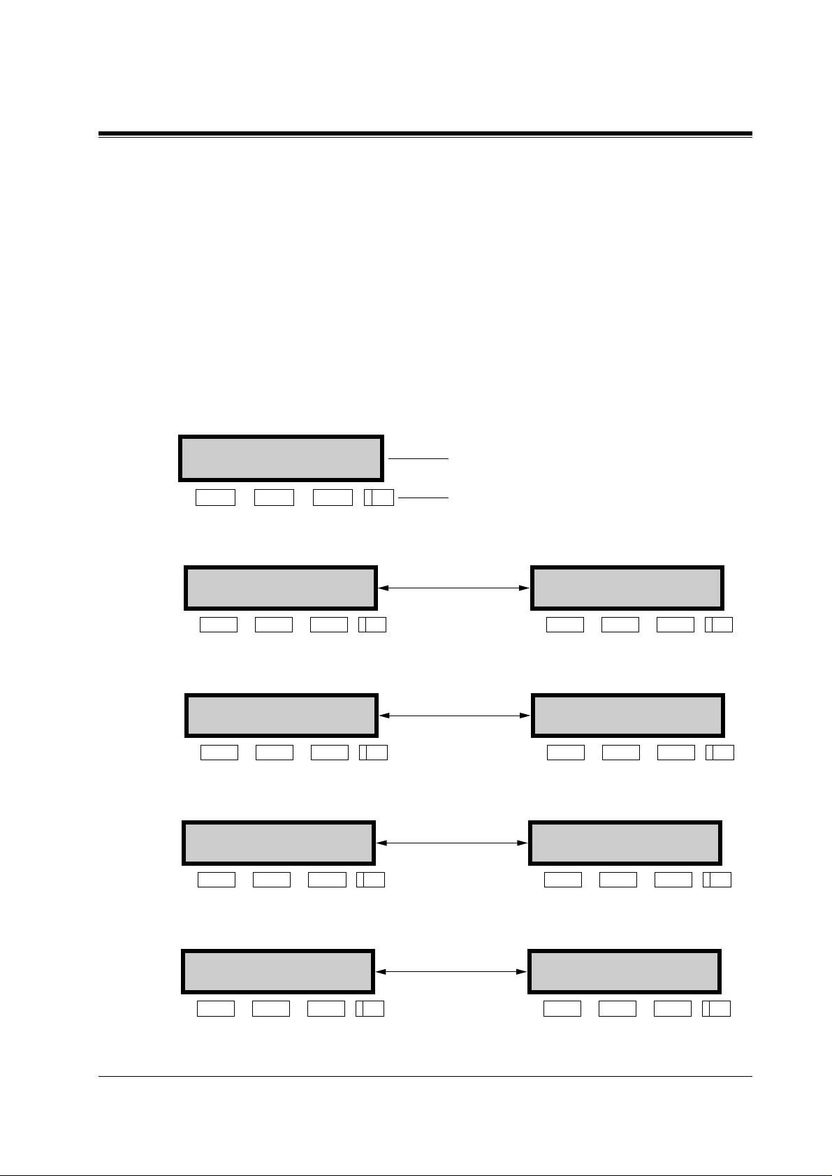
Soft Buttons and SHIFT Button on the Display DPT
Three soft buttons are provided just below the display of Digital Proprietary Telephones (DPT),
KX-T7533, KX-T7536, KX-T7433, KX-T7436, KX-T7230 and KX-T7235. The functions of
these soft buttons vary as the programming proce du res advance step by ste p. Those functions
that are currently assigned to the buttons are shown on the lower line of the display. (See
"Viewing the Display" in this section for mo re information on the dis p lay lines.)
If the
SHIFT
alternate betw een the two function s, press the
Soft button variations
Type 1
button indicator is on, two functions are available with each soft button. To
SHIFT
Example:
CLR NEXT
KX-T7230 Display
Buttons
1.2 Using Proprietary Telephones
button on the right side of the display.
Soft 1 Soft 2 Soft 3 SHIFT
Type 2
Press SHIFT
to alternate
SKP+ CLR NEXT
Soft 1 Soft 2 Soft 3 SHIFT
Type 3
Press SHIFT
to alternate
SEL+-> NEXT SEL-<- PREV
Soft 1 Soft 2 Soft 3 SHIFT Soft 1
Type 4
Press SHIFT
to alternate
BAC bac
Soft 1 Soft 2 Soft 3 SHIFT Soft 1
Type 5
Press SHIFT
to alternate
SKP+ SEL NEXT
SKP- PREV
Soft 1
Soft 2 Soft 3 SHIFT
Soft 2 Soft 3 SHIFT
Soft 2 Soft 3 SHIFT
SKP- CLR PREV
Soft 1 Soft 2 Soft 3 SHIFT
Soft 1
Soft 2 Soft 3 SHIFT
Programming Instructions 11
Page 12
1.2 Using Proprietary Telephones
You can use either the soft buttons or the overlay buttons. (For overlay buttons, refer to "Using
the Overlay" bel ow.)
Throughout programming you will see instructions such as "Press
buttons, t hi s m ean s pr es s
is performed.
Note
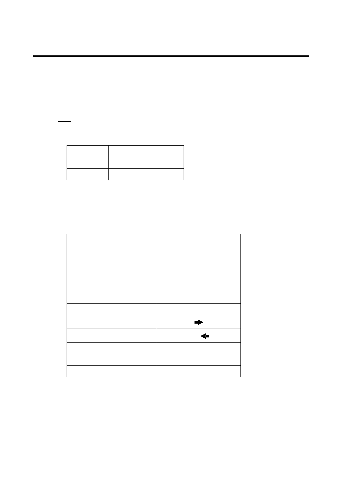
If you use soft buttons and i f programming instruc tions tel l you to press the fo ll owing buttons,
you may press soft buttons shown below.
Instructions Soft button
SHIFT
, release
SHIFT
and then press
". If you use soft
PREV
. The (PREV) function
Soft 3
SELECT
CLEAR
Using the Overlay
A progra mmin g overlay is packed wi th the tel ephone at the factory. This overlay should be
used at al l times while in pro grammi ng mode sinc e the functions of th e tele phone k e ys c hange
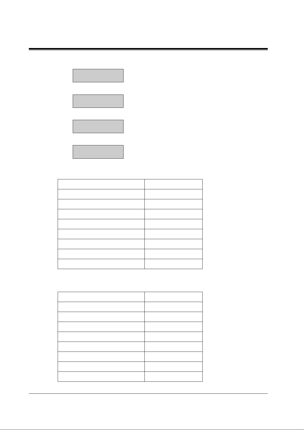
while in programming mode as follows: (The original functions are in parentheses.)
During Normal Operation During Programming
(AUTO ANSWER / MUTE) SELECT
CLR
, or
SEL
SEL+, SEL-
(PAUSE) PAUSE / PROGRAM
(SP-PHONE) NEXT
(REDIAL) PREV (PREVIOUS)
(FLASH) FLASH
(TRANSFER) CLEAR
(FWD/DND)
(CONF)
(INTERCOM) SECRET
(AUTO DIAL / STORE) STORE
(HOLD) END
— /
12 Programming Instructions
Page 13
1.2 Using Proprietary Telephones
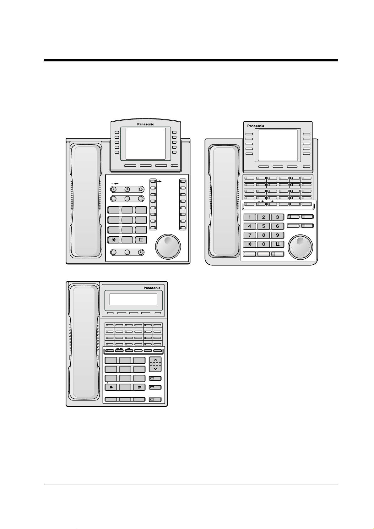
Location of Controls with the Overlay
The pictures below show the functions of the buttons of the proprietary telephone while in
programming mode. There are Overlays for the KX-T7500, KX-T7400 and KX-T7200 series
telephones. KX-T7536 and KX-T7230 are used for the examples.
REVERSE
*
,
SECRET
R
1QZ!? 2ABC 3DEF
ABC DEF
2
1
4GHI 5JKL 6MNO
GHI JKL MNO
4
5
7PQRS 8TUV 9WXYZ
PQRS TUV WXYZ
8
7
/+–=<> 0 . , ’ : ;
0
PREV END NEXT
KX-T7536
PROGRAM
PROG.INT
CLEARPAUSEFLASH
3
6
9
#$%&@( )
KX-T7536
SHIFT
612
511
410
3
28
17
SELECT STORE
9
KX-T7436
SECRET
1QZ!? 2ABC 3DEF
4GHI 5JKL 6MNO
7PRS 8TUV 9WXY
,
0., :; #$%&@( )
/+–=<>
*
PREV END NEXT
KX-T7436
SHIFT
PROGRAM PAUSE CLEAR
STORE
FLASH SELECT
CLEAR
3DEF
6MNO
9WXY
END
PAUSE
3
6
STORE
9
SELECT
NEXT
SECRET
1QZ!?
2ABC
1
2
4GHI
5JKL
475
7PRS
8TUV
8
/+–=<> 0.,’:; #$%&@( )
0
FLASHPREV
KX-T7230
Programming Instructions 13
Page 14
1.2 Using Proprietary Telephones
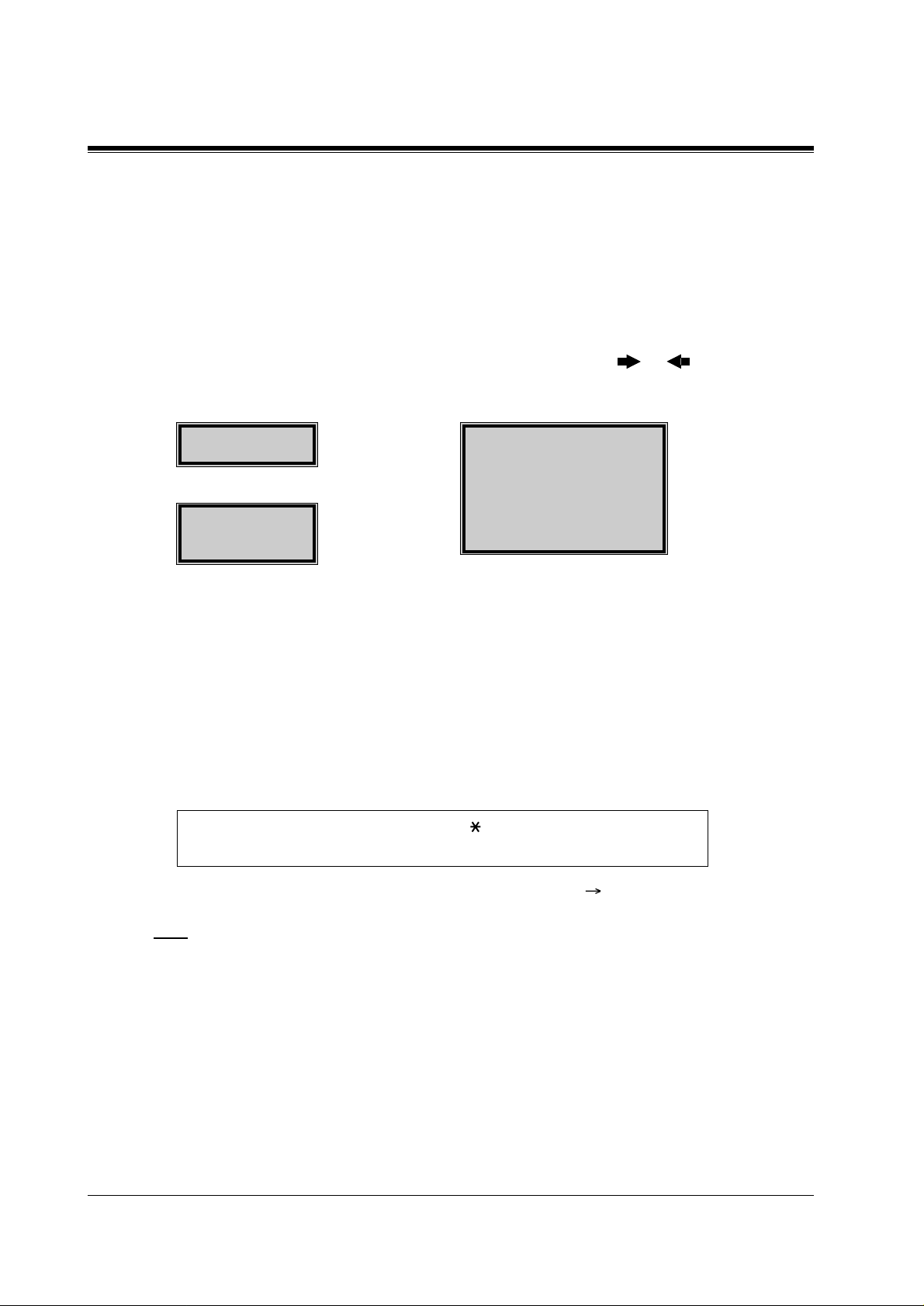
Viewing the Display
The display gives you helpful information, such as what you should do now, what you have
done, etc..
The KX-T7533, KX-T7536, KX-T7433, KX-T7436, KX-T7230 and the KX-T7235 utilise two
information l ines for programming. The upper li ne is called th e Message Line an d the lower
one is called the Function Line.
The Message Line (upper) shows you what you sh o uld do or what you should select. It also
allows you to confirm what you have just ent ered. The display capacity is 16 digits . If your
entry exceeds the capacity, you can shift the display by pressing or button.
The Function Line (lower) shows the current function of the soft buttons. These functions
change with the programming procedures.
SYS-PGM NO? →
CLR NEXT
2-Line Display
SYS-PGM NO? →
CLR NEXT
3-Line Display 6-Line Display
← Message Line
← Function Line
← Message Line
← Function Line
Before entering the programming mode
Before entering programming mode, confirm that:
• Your telephone is on-hook.
• No calls are on hold at your telephone.
Entering the programming mode
Press PROGRAM (or PAUSE) + + # and enter your System
Password (default=1234).
SYS-PGM NO? →
CLR NEXT
← Message Line
← Function Line
• The display shows the Initial Message:
SYG-PGM NO?
Note
• If your te lephone set does not have a
PROGRAM
button, substitute it with the
PAUSE
button.
• If nothing is entered in five seconds after the
PROGRAM
(or
PAUSE
) button is pres sed, it
is cancelle d.
• The System Password entered is not shown on the display. The System Password can be
changed by System Programming. Refer to Section 2.2 [107] System Password.
• During the programming mode, your extension is treated as a busy extension.
• Only one proprietary telephone can be in programming mode at any one time.
14 Programming Instructions
Page 15

1.3 Programming Methods
Advancing to the next stage
When "
SYS-PGM NO?
• To go to programme [000], press the
• To go to another programme, enter the 3-digit programme address.
Rotation of jack number
Each jack of the Digital Super Hybrid System supports the connection of a digital proprietary
telephone and a single line device with different extension numbers (eXtra Device Port: XDP
function) . To programme this function it is necessary to assign two parts for each jack. The first
part of jack one is 01-1. The second part of jack one is 01-2. The first part of jack two is 02-1
and so on. The
Example
#01-1
NEXT
NEXT
PREV
" is displayed, you can select one of the following:
and
#01-2
butto ns can be used t o move from jac k to jack a s required .
PREV
NEXT
#02-1 #02-2......
PREV
NEXT
NEXT
PREV
1.3 Programming Methods
button.
Note
The first part of a jack is for a DPT of a XDP-assigned jack. The second part is for a single line
device. Programme [600 ]EXtra Device Port assigns which jacks are XDP
Storing your data
Press
•The
STORE
to store your data.
STORE
indicator lights red and a confirmation tone is emitted.
* Confirmation tone (one beep)
After pressing
STORE
, you will hear a beep. This informs you that storage is completed.
* Alarm tone (three beeps)
If you hear this alarm, your entry is not valid.
Making another selection within the same programme address
• To make the next higher selection, press
• To make the previous selection, press
• To make a specific selection, press
NEXT.
PREV.
SELECT
and then enter the number.
Programming Instructions 15
Page 16

1.3 Programming Methods
Going to another programme address
After pressing
methods:
To go to the next larger programme address:
a)
Press
clockwise direction.
To go to the next smaller programme address:
Press
clockwise direction.
To go to a specific programme address:
b)
Press
Method (1) is useful when you want to perform a series of programmes consecutively. For
example, to change the programming in addresses [0XX], use this method. You can move from
[000] to [001], from [001] to [002], and so on by press ing th e
move in reverse order from [008] to [007], etc. by pressing the
This method can also be used to move between neighboring programme groups: For example,
you can move between the progra mm e add resses of the largest [0XX] and [100], the lar gest
[1XX] and [200], and s o on. A lso, you can move bet we e n the smallest progra mme address
[000] and the largest one [9XX].
Method (2) is useful when you wish to jump to another programme address. For example, you
have just finished with programme [006] and now you want to go to programme [301]. Neither
/
SKP+
END
VOLUME
and enter 301.
STORE,
Soft 1 (SKP+
SHIFT + Soft 1 (SKP–
END,
you can go to another programme with either o f the following two
then enter the programme Address.
nor
) or
VOLUME (DOWN)
) or
VOLUME (UP)
SKP–/VOLUME
or rorate the
or rorate the
SKP+
is convenient in this case. So you should press
or
SKP–
Jog Dial
or
in the counter-
Jog Dial
VOLUME
VOLUME
in the
. You can
.
Note
The following programming instructions assume that you have already entered the
programming mode and that you will use Method (b).
Confirming the entries
You may review the stored programming without making any changes.
Going back to the operation mode
Two ways are available to go back to the operation mode:
Lift the handset while in programming mode.
a)
When the Init ial Message:
b)
PAUSE)
button. (To display the Initial Message, press
SYS-PGM NO?
is displayed, press the
)
END.
PROGRAM (or
16 Programming Instructions
Page 17

1.4 Entering Characters
Entering Characters
You can enter characters to store names or messages by using the dialling key pad, buttons or
the Jog Dial.
See the Combination Tables below.
Combination Table a
1.4 Entering Characters
Soft button
SELECT button
pressing
times
S1
SHIFT+S1
S2
SHIFT+S2
S3
SHIFT+S3
SHIFT+
SHIFT+S1
01234567 8
SHIFT+
SHIFT+S2
keys
11QqZz!?
2 2AaBbCc
3 3DdEeFf
44GgHhIi
55JjKkLl
66MmNnOo
7 7PpQqRrS s
88TtUuVv
9 9WwXxY
yZ z
0 0 (space) . , ’ : ;
*/ +-=<>
##$%&@()
Programming Instructions 17
Page 18
1.4 Entering Characters
Combination Table b
Jog Dial
keys
1 1 Q q R r S s T t ···
2 2 A a B b C c D d ···
3 3 D d E e F f G g ···
4 4 G g H h I i J j ···
5 5 J j K k L l M m ···
6 6 M m N n O o P p ···
7 7 P p Q q R r S s ···
8 8 T t U u V v W w ···
9 9 W w X x Y y Z z (space) ···
0 0 (space) ! ? . , ’ : ; ···
# # $ % & @ ( ) A a B b ···
Display sequence by rotating the Jog Dial
* / + – = < > # $ ···
Note
• The alphabetical characters correspond to the letters shown on the twelve dialling keys on
the proprietary telephone. (exc ep t symbols)
•
In Combination Table a:
If your telephone is a KX-T7531, do not use the provided SELECT button. Use the AUTO
ANSWER/MUTE button which becomes the SELECT button when using the overlay.
•
In Combination Table b:
If you keep rotating the J og Di al, all of the characte rs in the table will be displayed.
Character Entering Methods
Please see the following example which shows how to select a desired character.
For example, to select the letter "M":
Select either of the following three methods:
Using the
1.
SHIFT
(for KX-T7533 / KX-T7536 / KX-T7433 / KX-T7436 / KX-T7230 / KX-T7235 only)
* See Combination Table a.
Press 6. ("M" belongs to "6".)
a)
• The Function Line shows: M N O
Press the
b)
(Press
SHIFT
Using the
2.
SELECT
* See Combination Table a.
Press 6. ("M" belongs to "6".)
a)
Press the
b)
and
(M) button.
Soft 1
to display the lower case of the above letters.)
SELECT
buttons
Soft
button
button once.
18 Programming Instructions
Page 19

1.4 Entering Characters
• Pressing the
letter. Pressing
and so on.
Using the
3.
(for KX-T7531 / KX-T7533 / KX-T7536 / KX-T7433 / KX-T7436 only)
* See Combination Table b.
Press 6. ("M" belongs to "6".)
a)
Rotate the
b)
• Rotating the
OR
Press
a)
Rotate the
b)
• If you keep rotating the Jog Dial, all of the characters will be displayed. For example,
Jog Dial
Rotating the
and so on.
any dialling keypad.
if you rotate the Jog Dia l after pressing 2, charact ers will appear in the following
order: A a B b •••• Z z (space) ! ? . , ' : ; * / + — = < > # $ % & @ ( ) A a B b ••••
SELECT
SELECT
Jog Dial
Jog Dial
Jog Dial
Jog Dial
button an appropriat e number of times gives you the desired
twice gives the letter "m", pressing three times gives "N",
one pulse.
an appropria te number of puls es gives you the desired lett er.
two pulses gives the letter "m", rotating three pulses gives "N",
until the des ir ed character appears.
Example of entering characters: to enter "Mike":
Using met hod (1)
* See Combination Table a.
Enter 6.
a)
6
M N O
Press
b)
Soft 1
M
M N O
Enter 4.
c)
M4
G H I
Press
d)
SHIFT
M4
g h i
Press
e)
Soft 3
Mi
g h i
(M).
.
(i).
Programming Instructions 19
Page 20
1.4 Entering Characters
Enter 5.
f)
Mi5
j k l
g)
Press
Soft 2
(k).
Mik
j k l
Enter 3.
h)
Mik3
d e f
i)
Press
Soft 2
(e).
Mike
d e f
Using method (2)
* See Combination Table a.
Procedures The display shows:
1. Enter 6.6
2. Press
3. Enter 4.M4
4. Press
5. Enter 5.Mi5
SELEC
SELECT
.M
six times. Mi
6. Press
7. Enter 3.Mik3
8. Press
Using method (3)
* See Combination Tabl e b.
1. Enter 6.6
2. Rotate
3. Enter 4.M4
4. Rotate
5. Enter 5.Mi5
6. Rotate
7. Enter 3.Mik3
8. Rotate
SELECT
SELECT
Jog D i a l
Jog D i a l
Jog D i a l
Jog D i a l
four times. Mik
four times. Mike
Procedures The display shows:
one pulse. M
six pulse. Mi
four pulses. Mik
four pulses. Mike
20 Programming Instructions
Page 21

OR
Procedures The display shows:
1. Enter 2.2
1.4 Entering Characters
2. Rotate
3. Enter 2.M2
4. Rotate
5. Enter 2.Mi2
6. Rotate
7. Enter 2.Mik2
8. Rotate
Note
• To erase all the letters, press
• To erase the last letter, press .
Jog Dial
Jog Dial
Jog Dial
Jog Dial
until "M" appears. M
until "i" appears. Mi
until "k" appears. Mik
until "e" appears. Mike
CLEAR.
Programming Instructions 21
Page 22

1.5 User Programming
1.5 User Programming Mode
User Programming Mode
Manager program m in g items (programme ad dress: [0XX]) are accessible by any display
proprietary telephone user in the system.
Entering the user programming mode
You can access these programmes by entering the User Programming Mod e as follows:
Before entering the mode, confirm that:
• Your telephone is on-hook.
• No calls are on hold at your telephone
Press PROGRAM (or PAUSE) + + and enter the User
Password (default=1234)
After entering the mode, perform the same programming steps as the system programming
steps in each programme address.
Note
• If your te lephone set does not have a
button.
• If nothing is entered in five seconds after the
is cancelle d.
• The User Password is not shown on the di splay. The passwor d can b e ch anged by system
programming. Refer to Section 2.2 [125]User Password.
• During the programming mode, your extension is treated as a busy extension.
• Only one proprietary telephone can be in programming mode at any one time.
PROGRAM
button, substitute it with the
PROGRAM
(or
PAUSE
PAUSE
) button is pres sed, it
22 Programming Instructions
Page 23

1.6 Programming Example
Programming Example
The following programming instructions assume that you have already entered the
programming mode and that you will employ method (b) of "Going to another programme
address" in Section 1.3 P rogramming Methods.
Example: programme [001] S ystem Speed Dialling Number Set
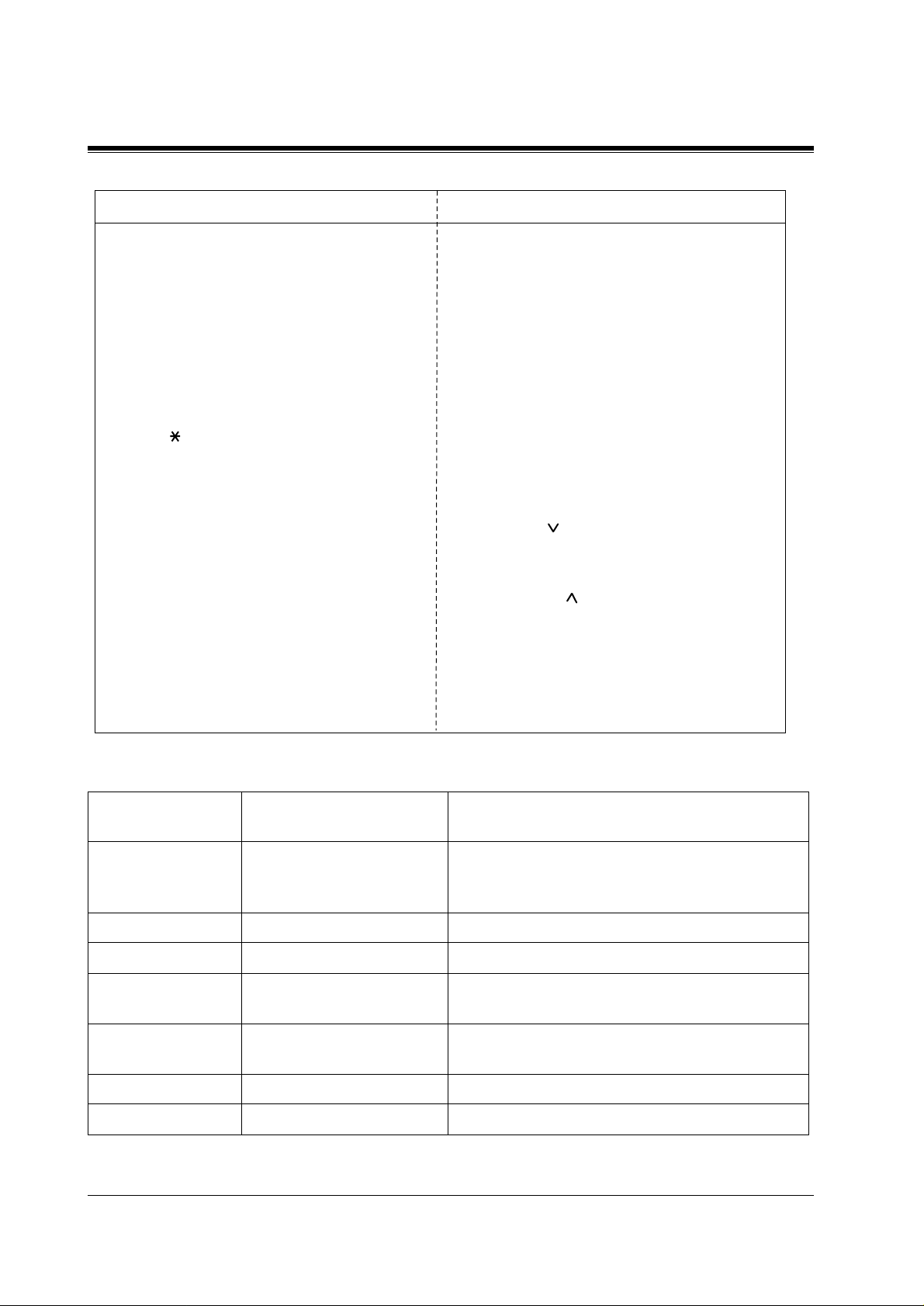
Sample of Description Explanation
[001]
(1)
System Speed Dialling Number Set
(2)
(1) Programme address.
(2) Programme title.
1.6 Programming Example
Description
Used to program the System Speed Dial numbers.
These numbers are available to all extension
users. There are 500 numbers from 000 through
499.
Selection
(4)
• Speed dial number: 000 through 499
• Telephone number: 24 digits (max.)
(5)
Default
All speed dial numbers – Not stored
Programming
1. Enter 001.
2. Press NEXT.
3. Enter a speed dial number.
4. Enter a telephone number.
5. Press STORE.
(3)
(6)
(7)
Display:
Display: SPD Code?→
To enter speed dial number 000,
you can also press NEXT.
Display example: 000:Not Stored
To delete the current entry, press CLEAR.
To change the current entry, press
CLEAR and enter the new number.
SPD Number Set
(9)
(14)
(8)
(10)
(12)
(3) Provides a more detailed description of the
programme.
(4) Shows you choices that you can assign.
(5) Shows you the default (factory setting).
(6) Shows you programming procedures step by step.
• While programming, use the overlay.
• Before starting to programme, enter the
programming mode. (See Entering the
programming mode in Section 1.2 Using
Proprietary Telephones.)
(7) Enter the programme address.
(8)
The display shows the programme title. If your
telephone has soft buttons, the lower line shows
the functions that are currently assigned to them.
Press either Soft 3 (NEXT)shown on the display
(9)
or the NEXT shown on the overlay.
(10) The message line advises you to enter a speed dial
number.
(11) If the telephone number has already been stored,
(11)
the number is displayed.
(12) Enter the telephone number that you want to store.
(13)
Your entry is displayed as you enter the digits.
(13) Pressing CLEAR erases the whole entry.
(14) Your entry is now stored.
The indicator lights red and a confirmation tone
lets you know that storage is completed.
Programming Instructions 23
Page 24
1.6 Programming Example
Sample of Description Explanation
6.
To programme another speed dial number,
press NEXT or PREV, or SELECT and
the desired speed dial number
7. Repeat steps 4 through 6.
8. Press END.
Conditions
Features Guide References
(18)
• Each speed dial number has a maximum of 24
digits. The valid characters are 0 through 9,
and #
keys, FLASH, PAUSE, SECRET
and
– (hyphen) buttons.
System Speed Dialling
(17)
(19)
(15) Select the best way for you to store another speed
(15)
.
(16)
•
•
•
•
•
•
•
•
dial number. Pressing the NEXT / PREV allows
you to select the next higher / lower speed dial
number. You can also keep pressing them until the
desired one is displayed. If you press SELECT
and the desired speed dial number, the selected
code is displayed.
(16) You can continue to programme another entry.
(17) After you have stored all your entries, finish this
programme by pressing END. After pressing END
you can go to any programme address you desire.
You can return to the Initial Message mode any
time by pressing END.
To go to the next larger programme address, do not
press END but press Soft 1 (SKP+) or
VOLUME
counter-clockwise direction.
To go to the next smaller programme address, do
not press END but press SHIFT + Soft 1 (SKP-)
or VOLUME
counter-clockwise direction.
(18) Tells you what you should notice or consider when
doing the programming.
(19) Lists all of the features related to the
programming. These features are described in
the Features Guide.
or rorate the Jog Dial in the
or rorate the Jog Dial in the
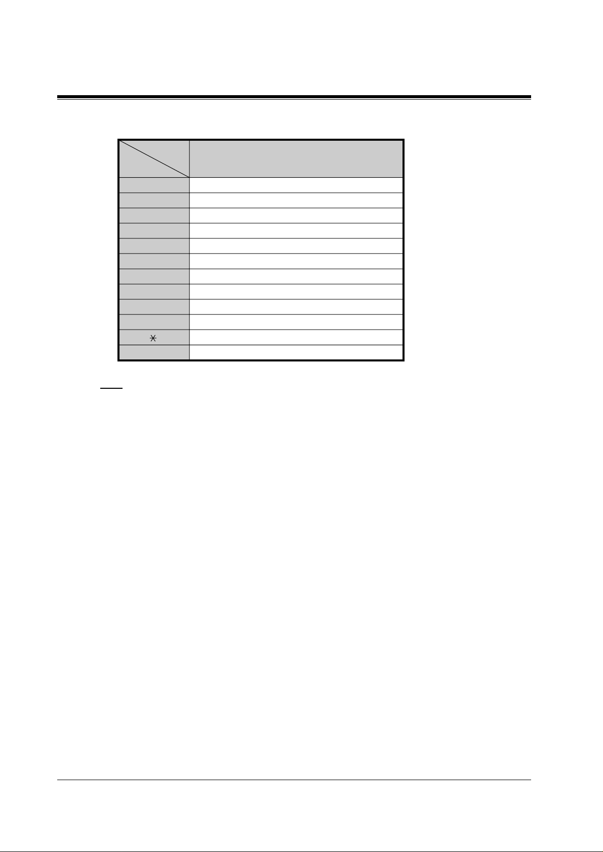
Programming Structur
Programme
Programming Group Description
Address
[0XX] Manager Programming These programmes may be accessed by the syste
manager of the customer to meet frequent changes
requested by the customer.
[1XX] System Programming Entire system programming.
[2XX] Timer Programming Flexible system timer setting.
[3XX] TRS / ARS / TIE Line
Routing Table Programming
[4XX] Outside Line / ISDN Line /
TIE Line Programming
Assignment of Toll Restriction, Automatic Route
Selection (AR S) or TIE Line Routing Table.
Setting of outside line , outside line group, ISDN line
or TIE line values.
[5XX] COS Programming Setting of Class of Servic e (C OS ).
[6XX] Ext en s ion Programming Setting of extensio n values.
24 Programming Instructions
Page 25

Programming Stru ctur
1.6 Programming Example
Programme
Address
[8XX] Reso urce Programming Assignment of customer-supplied peripherals
[9XX] Optional Programming Used to answer the user's requirements or troubles,
Programming Group Description
connected to the system.
if needed.
Programming Instructions 25
Page 26

1.6 Programming Example
26 Programming Instructions
Page 27

Section
General Programming
General Programming 27
Page 28

2.1 Manager Programming
2.1 Manager Programming
[000] D ate and Time Set
Description
Sets the current date and time.
Selection
•Year:
• Month:
•Day:
• Day of the week:
• Hour:
• Minute:
•
AM / PM
Default
'95 Jan. 1 SUN 00:00
Programming
Enter
1.
Display: Day / Time set
Press
2.
Display example: '95 Jan. 1 SUN
Enter the
3.
To change the current entry, press
00 through 99
Jan. through Dec.
1 through 31
SUN / MON / TUE / WED / THU / FRI / SAT
00 through 23
00 through 59
.
000
NEXT.
year.
CLEAR
and enter the new year
Press .
4.
Keep pressing
5.
Press .
6.
Enter the
7.
To change the current entry, press
Press .
8.
Keep pressing
9.
Press
10.
11.
12.
STORE.
Press
NEXT.
Display example: 12:00 PM
Enter the
SELECT
day.
SELECT
hour.
until the desired month is displayed.
CLEAR
until the desired day of the week is displayed.
and enter the new day
28 General Programming
Page 29

2.1 Manager Programming
Press .
13.
Enter the
14.
Press .
15.
Press
16.
Press
17.
Press
18.
Conditions
• After changing an entry, you can press
steps.
• To return to a previous field, press in steps 4 through 9 and steps 13 through 16.
• If you hear an alarm after pressing
• The clock starts imm e diately after the
• You cannot leave an entry empty.
To change the current entry, press
minute.
To change the current entry, press
SELECT
STORE.
END.
for AM or PM.
STORE,
CLEAR
CLEAR
STORE.
STORE
and enter the new hour.
and enter the new minute.
You do not have to perform the rest of the
check that the date is valid.
button is pressed.
Features Guide References
Display Message
General Programming 29
Page 30

2.1 Manager Programming
[001] S ystem Speed Dialling Number Set
Description
Used to programme the System Speed Dial nu mbers. These num b ers are available to all
extension users. There a r e 50 0 numbers available from 000 to 499.
Selection
• Speed dial n umber:
• Telephone numb er:
Default
All speed dial numbers – Not stored
Programming
Enter
1.
Display: SPD Number Set
Press
2.
Display: SPD Code?
Enter a
3.
To enter speed dial number 000, you can also press
Display example: 000:Not Stored
Enter a
4.
To delete the current entry, press
To change the current entry, press
Press
5.
To programme another sp eed dial number, pres s
6.
desired
Repeat steps 4 through 6.
7.
Press
8.
000 through 499
24 digits (max.)
001.
NEXT.
speed dial number
telephone number.
STORE.
speed dial numbe
END.
NEXT.
CLEAR.
CLEAR
.
and enter the new number.
NEXT
or
PREV,
or
SELECT
and the
30 General Programming
Page 31

Conditions
2.1 Manager Programming
• Each speed dial number has a maximum of 24 digits. The valid characters are
the and # keys, and the
– To store a flash signal, press
Note:
The stored flash will only be effective during a call. (Refer to External Feature Access
in the Featur e s Guide.)
– To store a hyphen, press the "–" button.
– To store a pause, press
Features Guide.)
– T o store a feature number to convert pulse signals to DTMF (Dual T o ne Multi-Frequency)
signals, pr ess the and # keys.
(Re fer to Pulse to Tone Co nversion in the F e atures Guide.)
– To prevent displaying of all or part of the number, press
secret number. (Secret Dialling)
• If you are storing an external number, include the line access number (default: 9, 81 through
88) before the number. When dialling, a pause is automatically inserted after the line access
number
• If you are storing a n acc oun t code, enter the account code before the line access number.
(Refer to Account Code Entry in the Features Guide.)
• If you are storing a number for Incoming Outside Call Information Display with name,
enter "–" (hyphen) after the line access number. The system starts to compare the calling
party's number or cal led party's number with the System Speed Diallin g number stored after
"–".
Example: 9 – 12345678
(Refer to Incoming Outside Call Information Display in the Features Guide.)
• A number co nsisting of 25 digits or more can be stored by storing it in t w o spe ed dial
numbers . The li ne access number shou ld be stored in the first speed d ial number.
• To access another sp eed dial number in step 6, press
FLASH, PAUSE, SECRET
FLASH.
PAUSE.
(Refer to Pause In sertion, Automatic in the
and
– (hyphen)
SECRET
SELECT
before and after the
and start with step 3.
0 through 9,
buttons.
• To display parts of the number which have scrolled off the display, press or .
• Programme [ 002]System Speed Dialling Name Set is used to name the speed dial
numbers.
Features Guide References
Call Directory
System Speed Dialling
General Programming 31
Page 32

2.1 Manager Programming
[002] S ystem Speed Dialling Name Set
Description
Assigns names to the system speed dial numbers assigned in program me [001]System Speed
Dialling Number Set. KX-T7531, KX-T7533, KX-T7536, KX-T7433, KX-T7436 and KXT7235 telephones can show the st ored name during Sys tem Sp eed Dialling.
Selection
• Speed dial n umber:
•Name:
Default
All speed dial numbers – Not stored
Programming
Enter
1.
Display: SPD Name Set
Press
2.
Display: SPD Code?
Enter a
3.
To enter speed dial number 000, you can also press
Display example: 000:Not Stored
Enter a
4.
For entering characters, see Section 1.4 Entering Characters.
To delete the current entry, press
To change the current entry, press
Press
5.
To programme another sp eed dial number, pres s
6.
desired
Repeat steps 4 through 6.
7.
Press
8.
000 through 499
10 characters (max.)
002.
NEXT.
speed dial number
name.
STORE.
speed dial number.
END.
CLEA
CLEAR
NEXT.
.
and enter the new name.
NEXT
or
PREV,
or
SELECT
and the
Conditions
• Speed dial numbers are progra mmed in programme [001 ]System Speed Di alling Number
Set.
• To go to another speed d ial number in ste p 6, press
SELECT
32 General Programming
and start with step 3.
Page 33

Features Guide References
Call Directory
System Speed Dialling
2.1 Manager Programming
General Programming 33
Page 34

2.1 Manager Programming
[003] E xtension Number Set
Description
Assigns an extension number to each extension.
Selection
• Jack number:
KX-TD816 –
KX-TD1232 –
(-1 = first part, -2 = second part)
• Extension Number:
Default
KX-TD816:
Jack 01-1 through 16-1 = 101 through 116;
Jack 01-2 through 16-2 = 201 through 216
KX-TD1232:
Jack 01-1 through 64-1 = 101 through 164;
Jack 01-2 through 64-2 = 201 through 264
01 through 16 (-1 / -2)
01 through 64 (-1 / -2)
2 through 4 digits
Programming
Enter
1.
Display: EXT Number Set
Press
2.
Display: Jack NO?
Enter a
3.
To enter jack number 01, you can also press
To select the second part ( -2) , press
Display: #01-1:EXT101
Enter an
4.
To change the current entry, press
Press
5.
To programme another jack, press
6.
number.
Repeat steps 4 through 6.
7.
Press
8.
003.
NEXT.
jack number.
extension number.
STORE.
END.
NEXT
CLEAR
NEXT
NEXT.
after entering the jack number.
and enter the new number.
or
PREV,
or
SELECT
and the desired
jack
34 General Programming
Page 35

Conditions
• There is a maximum of 32 extension numbers for KX-TD816, and 128 extension numbers
for KX-TD1232. Each extension number can be two, three, or four digits, consisting of
through 9.
• For the KX-TD1232, jack numbers 01 through 32 are for the Master System and 33 through
64 are fo r the Slave, if avai lable.
• An extension number i s invalid if the first o r second digit s do not match with th e programme
[10 0]Flexible Numbering, (01) - (16) 1st through 16th hundred extension blocks" setting.
If one digit is assigned as the leading digit, some extensions have two digits and some have
three digits. If two digits are assigned, some have three digits and some have four digits.
• Two extension numbers can be assigned per jack. If eXtra Device Port (XDP) is disabled
for the jack in programme [600] EXtra Device Port, the extension number of the second
part (XX-2) is not available. (XX=jack number)
• For an explanation o f ja c k numbering, see "Rotation of jack nu mber" in Section
1.3 Programming Methods.
• Double entry and incompatible entry for these numbers are invalid. Valid entry example: 10
and 11, 10 and 110. Invalid entry example: 10 and 106, 210 and 21.
To avoid making a n invalid entry, check the other extension num bers. The default of each
extension number is as follows:
[012] ISDN Extension Number Set
Not stored.
[118] VM Extension Number Set
KX-TD816 – 165 through 178
KX-TD1232 – 165 through 180
[130] Phantom Extension Number Set
Not stored.
[813] Floating Number Assignment
KX-TD816 – 191 through 194, 196, 198, 199, 291 throu gh 2 9 4, 298, 299
KX-TD1232 – 191 through 194, 1 9 6 th ro ug h 199, 291 through 294, 296 through 299
[671] PS Extension Number Set
Not stored.
• Programme [ 004]Exten si on N a me Set is used to name the extens i on numbers.
2.1 Manager Programming
0
The and # keys cannot be used.
Features Guide References
Call Directory
Display Message
EXtra Device Port (XDP)
Flexible Number in g
Intercom Calling
General Programming 35
Page 36

2.1 Manager Programming
[004] E xtension Name Set
Description
Assigns names to the extension numbers programmed in program me [ 00 3 ]Extension
Number Set .
Selection
• Jack number:
Default
KX-TD816 –
KX-TD1232 –
(-1 = first part, -2 = secon d part)
•Name:
All jacks – Not stored
10 characters (max.)
01 through 16 (-1 / -2)
01 through 64 (-1 / -2)
Programming
Enter
1.
Display: EXT Name Set
Press
2.
Display: Jack NO?
Enter a
3.
To enter jack number 01, you can also press
To select the second part ( -2) , press
Display: #01-1:Not Stored
Enter a
4.
For entering characters, see Section 1.4 Entering Characters.
To delete the current entry, press
To change the current entry, press
Press
5.
To programme another jack, press
6.
number.
Repeat steps 4 through 6.
7.
Press
8.
004.
NEXT.
jack number.
name.
STORE.
END.
NEXT
CLEAR.
CLEAR
NEXT
NEXT.
after entering a jack number.
and enter the new name.
or
PREV
, or
SELECT
and the desired
jack
Conditions
• There is a maximum of 32 names for KX-TD816, and 128 names for KX-TD1232. Each
name has a maximum of 10 characters.
36 General Programming
Page 37

• For the KX-TD1232, jack numbers 01 through 32 are for the Master System and 33 through
64 are fo r the Slave, if avai lable.
• For an explanation o f ja c k numbering, see "Rotation of jack nu mber" in Section
1.3 Programming Methods.
Features Guide References
Call Directory
Display Message
Intercom Calling
2.1 Manager Programming
General Programming 37
Page 38

2.1 Manager Programming
[005] F lexible CO Button Assignment
Description
Used to determine the use of the flexible CO buttons on proprietary telephones from a
centralised telephone.
Selection
• Jack number:
KX-TD816 –
KX-TD1232 –
• Button Code (plus parameter, if required):
Button Code Parameter
01 through 16
01 through 64
(Single-CO) KX-TD816:
0
KX-TD1232:
(DSS)
1
(One-Touch Dialling)
2
(Message Waiting) None
3
(FWD/DND) None
4
(Save) None
5
(Account) None
6
(Conference) None
7
(Log-In/Log-Out) None
80
(Voice Mail Transfer)
82
(Two-Way Record)*
83
(Two-Way Transfer)*
84
(Live Call Screening)* None
85
(Live Call Screening Cancel)* None
86
(Alert) None
87
2 through 4 digits
16 digits max
2 through 4 digits
2 through 4 digits
2 through 4 digits
01 through 08
01 through 54
(Extension number)
. (Telephone number)
(Voice mail extension number)
(Voice mail extension number)
(Voice mail extension number)
(Outside line number)
(Outside line number)
(Phantom Extension)
88
(ISDN Service)
89
(Night)
8
(Loop-CO)
(Group-CO 1 through 8 (Outside line group number)
#
(Ringer frequency) 1 through 8 (Ring tone type number)
CO
2 through 4 digits
16 digits max
None
None
(Phantom extension number)
. (ISDN service numb er)
38 General Programming
Page 39

2.1 Manager Programming
* Available when this system is con n ected to a Voic e Processing Sy stem which supports digital
proprietary telephone integration (e.g. KX-TVP200).
Default
KX-TD816:
All jacks – CO buttons 1 through 8 = Single-CO 01 through 08; Ring tone type 2
Other CO buttons = Not stored
KX-TD1232:
All jacks – CO buttons 1 through 24 = Single-CO 01 through 24; Ring tone type 2
Programming
Enter
1.
2.
3.
4.
5.
6.
7.
8.
005.
Display: Flexible Key Asn
Press
NEXT.
Display: Jack NO?
Enter a
Press the
Enter a
Press
To programme another CO button of the same jack, re peat steps 4 through 6.
To programme another jack, press
Press
jack number.
To enter jack number 01, you can also press
Display: PT—PGM Mode
CO button
The display sh ows the contents pre-as signed to the butt on.
Display example: CO-01
button code
To change the parameter, press
STORE.
END.
which is changed to another button.
(plus
parameter
, if required).
CLEAR
SELECT
NEXT.
and enter the new parameter.
and repeat steps 3 through 6.
Cancelling
Perform the same procedures as steps 1 through 4 above.
1.
Enter
2.
3.
4.
Press
Press
2.
STORE.
END.
Conditions
• A centralise d telephone is a telepho ne connected to jack 01 or a jack programmed as a
manager extension in programme [006]Op erator / Manager Extension Assignment.
General Programming 39
Page 40

2.1 Manager Programming
• For the KX-TD1232, jack numbers 01 through 32 are for the Master System and 33 through
64 are for the Slave, if availabl e. Jack numbers in the out-of-service system are
unacceptable.
• The number of the CO buttons available depends on the telephone type. (Refer to Buttons
on Proprietary Telephones and Consoles in the Features Guide.) For the KX-T7500 series
telephones, 24 CO buttons can be programmed by adding 12 CO buttons by connecting the
KX-T7545 Add-on key Module.
• If you press the sam e CO button ag ain in step 5, y o u can select a desired ringer frequency
for the CO button from eight types of ring tones. When you enter the tone type number (1
through 8), you will hear the selected tone type until
possible only for the CO buttons that have been assigned to Single-CO, Group-CO, or
Loop-CO.
Features Guide References
Button, Flexible
Buttons on Propr ie tary Telephones and Consoles
STORE
is pressed. This selection is
40 General Programming
Page 41

[006] Operator / Manager Extension Assignment
Description
Assigns the jack number for a manager and/or operators. The manager extension can perfor
System Programming. The operators have th e ability to p erform operator services.
Selection
2.1 Manager Programming
•
OPE-1
• Jack number:
KX-TD816 –
KX-TD1232 –
Default
Operator 1 – Jack 01;
Operator 2 and Manager – Not stored
Programming
Enter
1.
Display: Operator / Manage
Press
2.
Display: OPE-1:Jack01
To programme another item, you can also keep pressing
desired one is displayed.
Enter a
3.
To assign no operator or manager, press
To change the current entry, press
Press
4.
To programme another item, press
5.
Repeat steps 3 through 5.
6.
Press
7.
(operator 1) /
006.
NEXT
STORE.
END.
to programme operator 1.
jack number.
OPE-2
01 through 16
01 through 64
(operator 2) /
CLEAR
NEXT
MNGER
CLEAR.
or
PREV.
(manager)
NEXT
and enter the new jack number.
or
PREV
until the
Conditions
• Up to two operators and a manager can be progr ammed.
• For the KX-TD1232, jack numbers 01 through 32 are for the Master System and 33 through
64 are fo r the Slave, if avai lable.
• The manager cannot be assigned the jack number of the Console Port set in programme
[00 7]Console Port and Paired Telephone Assignment.
• If the assigned jack is in eXtra Device Port (XDP) mode, the proprietary telephone jack is
treated as the manager / operator extension.
General Programming 41
Page 42

2.1 Manager Programming
Features Guide References
Manager Extension
Operator
42 General Programming
Page 43

2.1 Manager Programming
[007] Console Port and Paired Telephone Assignment
Description
Assigns the jack numbers for the console and the paired extension.
Selection
• Console number:
KX-TD816 –
KX-TD1232 –
• Jack number for Console:
KX-TD816 –
KX-TD1232 –
• Jack number for paired extension:
KX-TD816 –
KX-TD1232 –
1 through 4
1 through 4
02 through 16
02 through 32
01 through 16
01 through 32
(for Master),
5 through 8
(for Master),
(for Master),
(for Slave)
33 through 64
33 through 64
(for Slave)
(for Slave)
Default
All consoles – Not stored
Programming
Enter
1.
Display: DSS Console Asn
Press
2.
Display: DSS NO?
Enter a
3.
To enter console number 1, you can also press
Display example: DSS—1:# P:#
Enter a
4.
To delete the current entry, press
To change the current entry, press
Press .
5.
Enter a
6.
To change the current entry, press
Display example: DSS—1:#02 P:#03
Press
7.
To programme another console, press
8.
console number
Repeat steps 4 through 8.
9.
Press
10.
007.
NEXT.
console number.
jack number
jack number
STORE.
.
END
for the console.
CLEAR.
CLEAR
for the paired extension.
CLEAR
NEXT
NEXT.
and enter the new jack number.
and enter the new jack number.
or
PREV
, or
SELECT
and the desired
General Programming 43
Page 44

2.1 Manager Programming
Conditions
• The jack number for the console and that for the paired extension must be entered together.
• Multiple consoles cannot be assigned to the same console jack.
• Multiple consoles can be paired with the same proprietary telephone jack.
• A console jack cannot be assigned the jack 01 and the jack number of manager set in
programme [ 006]Operator / Manager Extension Assignment.
• If all incoming outside calls are set to ring at the operator extension telephone in programme
[407-4 08]DIL 1:1 Extension – Day / Night, assigning a console to the operator extension
makes the operator's job much easier.
• If a single line telephone is assigned as the pair extension, the paired console will not
function.
• If a console - assigned jack is programmed fo r eXtra Device Port (XDP), a single line
telephone can be connected to the jack in parallel w ith the console.
Features Guide References
Console
44 General Programming
Page 45

[008] Absent Messages
Description
Used to programme the absent me ssages. An absent mes s ag e, if set by the extension user, is
displayed on the calling exten sion's telephone to show the reason for the user's absence.
Selection
2.1 Manager Programming
• Message number:
• Message:
Default
1: Will Return Soon
2: Gone Home
3: At Ext %%%
4: Back at %%:%%
5: Out Until %%/%%
6: In a Meeting
7 through 9: Blank (n ot stored)
Programming
Enter
1.
Display: Message Asn
Press
2.
Display: MSG NO?
Enter a
3.
To enter message number 1, you can also press
Display example: MSG1:Will Return
Enter the
4.
For entering ch ar acters, see Section 1 .4Entering Characters.
To delete the current entry, press
To change the current entry, press
Press
5.
To programme another message, press
6.
message numbe
Repeat steps 4 through 6.
7.
Press
8.
1 through 9
16 characters (max.)
.
008
.
NEXT
message number
message
STORE
.
END
.
.
.
.
.
NEXT
NEXT
.
and enter the new message.
or
PREV
, or
SELECT
and the desired
CLEAR
CLEAR
General Programming 45
Page 46

2.1 Manager Programming
Conditions
• Messages 1 through 6 are programmed at the factory but can be changed.
• You can enter a maximum of seven "%" characters per message which can be programmed
at each user's extension. The extension user can en ter
characters. If the user enters digits less than the number of "%" characters, it is
recommended to fill the remaining "%" characters with "#" or " ".
• If there are 4-digit extension numbers available in your system, add one "%" to Message 3.
• To display parts of the message which have scrolled off the display, press or .
Features Guide References
Absent Message Capability
0 through 9,
and # for the %
46 General Programming
Page 47

[009] Emergency Dial Number Set
Description
Assigns em ergency call numbers.
Selection
2.1 Manager Programming
• Emergency dial location number:
• Telephone number:
Default
All locations – Not stored
Programming
Enter
1.
Display: Emergency Call
Press
2.
Display: Emergency NO?
Enter an
3.
To enter emergency number 1, you can also press
Display example: 1:9110
Enter a
4.
To delete the current entry, press
To change the current entry, press
Press
5.
To programme ano th er emergency dial number, press
6.
the desired
Repeat steps 4 through 6.
7.
Press
8.
1 through 8
16 digits (max. )
.
009
.
NEXT
emergency dial location numbe
telephone numbe
STORE
END
.
emergency dial location numbe
.
.
CLEAR
CLEAR
.
.
NEXT
.
and enter the new number.
NEXT
.
or
PREV
, or
SELECT
and
Conditions
• There is a maximum of ei ght eme rg en cy call numb ers. Eac h number has a maximum of 16
digits, consisting of
• No restriction is applied to emergency call numbers.
• For outside calls, enter a line access number (9, 81 through 88) before the phone number.
• Emergency dial location number (1-8) corresponds to [100] Flexible Numbering – No. 55-
62.
0 through 9, , #, F (Flash), P (Pause)
General Programming 47
and
– (hyphen)
.
Page 48

2.1 Manager Programming
Features Guide References
Emergency Call
48 General Programming
Page 49

[010] Budget Management
Description
Assigns the charge limitatio n of a ca ll on the extension basis.
Selection
• Jack number:
KX-TD816 –
KX-TD1232 –
( =all jacks, -1=first part, -2=second part)
• Charge limitation (Charge):
Default
All jacks – 0
01 through 16
01 through 64
,
(-1 / -2)
,
(-1 / -2)
0 through 59999
2.1 Manager Programming
Programming
Enter
1.
Display: Charge Limit
Press
2.
Display: Jack NO?
Enter a
3.
To enter jack number 01, you can also press
Display example: #01-1: 0
Enter a
4.
To delete the charge limitation, press
Press
5.
To programme another jack, press
6.
numbe
Repeat steps 4 through 6.
7.
Press
8.
Conditions
• If the charge limitation is set "0", no restr ic tion is appl ied.
• For the KX-TD1232, jack numbers 01 through 32 are for the Master System and 33 through
64 are fo r the Slave, if avai lable.
.
010
.
NEXT
jack number
charge limitation
STORE
END
.
.
.
.
.
NEXT
.
.
PREV
, or
SELECT
and the desired
jack
NEXT
CLEAR
or
• To assign all jack numbers to one selection, press the key in step 3. In this case, the
display shows the contents programmed for Jack 01.
General Programming 49
Page 50

2.1 Manager Programming
• The displayed cur re ncy denomination can be programmed by [121]Assignment of
Denomination.
Features Guide References
Budget Management
Charge Fee Reference
50 General Programming
Page 51

[011] Charge Margin Rate
Description
Assigns the margin rate of a telephone charge.
Selection
2.1 Manager Programming
Margin (% ):
Default
0%
Programming
Enter
1.
Display: Charge Margin
Press
2.
Display: Margin: 0%
Enter a
3.
To delete the charge limitation, press
Press
4.
Press
5.
Conditions
Telephone charge = Real charge x ( )
The telephone charge will be printed out when checking out.
0 through 999
.
011
.
NEXT
charge mar gin rate
STORE
END
.
.
.
CLEAR
100 + rate
100
.
Features Guide References
Hotel Application
General Programming 51
Page 52

2.1 Manager Programming
[015] Q uick Dialling Number Set
Description
Stores the desired extension or telephone numbers for Quick Dialling.
Quick dialling numbe rs m ust be assigned in pr ogramme [104]F lexible Quick Dialling
Number Set .
Selection
• Location numb er :
• Desired number:
Default
All location numbers – Not stored
Programming
Enter
1.
Display: Quick Dial
Press
2.
Display: Location NO?
Enter a
3.
To enter location number 01, you can also press
Display example: 01:Not Stored
Enter a
4.
To delete the current entry, press
To change the current entry, press
Press
5.
To programme another location, press
6.
location number.
Repeat steps 4 through 6.
7.
Press
8.
01 through 80
16 digits (max.)
015.
NEXT.
location nu mber.
desired number
STORE.
END.
CLEAR.
CLEAR
NEXT
NEXT.
and enter the new number.
or
PREV
, or
SELECT
and the desired
Conditions
• Each quick dialling number has a maximum of 16 digits, consisting of
F (FLASH), P (PAUSE)
and
– (hyphen)
.
0 through 9
, ,
#,
Features Guide References
Quick Dialling
52 General Programming
Page 53

2.2 System Programming
[100] Flexible Numbering
Description
Assigns the leading digits of extension numbers and feature numbers for system features.
Feature Number List
Number Feature Default
01 1st hundred extension block 1
02 2nd hundred extension block 2
03 - 16 3rd thro ugh 16th hundred exte nsion block None
17 Operator call 0
18 Automatic line access / ARS 9
2.2 System Programming
19 Outside line group line access 8
20 System speed dialling
21 Station speed dialling
22 Station speed dialling programming 30
23 Doorphone c all 31
24 Paging – external 32
25 Paging – external answer / TAFAS answer 42
26 Paging – group 33
27 Paging – group answer 43
28 Call pickup, outs ide line
29 Call pickup, group 40
30 Call pickup, directed 41
31 Call hold 50
32 Call hold retrieve – intercom 51
33 Call hold retrieve – outside line 53
3
4
34 Last number redial #
35 Call park / Call park retrieve 52
36 Account code entry 49
37 Door opener 55
General Programming 53
Page 54

2.2 System Programming
Number Feature Default
38 External feature access 6
39 Station feat ur e clear 790
40 Message wai ting 70
41 Outgoing message 36
42 Call forwarding / Do not disturb 710
43 Call pickup deny 720
44 Data line security 730
45 Call waiting / OHCA / Whisper OHCA 731
46 Ex ecutive busy override deny 733
47 Pickup dialling 74
48 Absent message 750
Feature Number List
49 Timed reminder 76
50 Electronic station lockout 77
51 Night service mode 78
52 Parallel tele p h on e mode 39
53 Background music – external 35
54 Reserved
55-62 Emergency cal l 1 th rough 8 None
63 Timed reminder, remote
64 Call log, incoming 56
65 Call log lock, inco ming 57
66 Check-out ready 736
67 TIE line access number None
68-83 Other PBX Extension 01 through 16 None
84 LCS password set / cancel 799
85 Log-in / log-out 45
7
86 SXDP 48
87 CLIP / COLP 711
88 Reserved
89 MCID 737
54 General Programming
Page 55

Selection
2.2 System Programming
• Selection number:
features.)
• Feature number:
1 or 2 digits
1 through 3 digits
Default
See "Feature Number List".
Programming
Enter
1.
Display: FLX Numbering
Press
2.
Display: Select NO?
Enter a
3.
To enter selection number 01, you can also press
Display example: 01. 1-EXT BL:1
Enter the
4.
To delete the feature number, press
To change the current entry, press
Press
5.
To programme another selection, press
6.
selection number.
Repeat steps 4 through 6.
7.
Press
8.
01 through 89
(for selection nu mbers 01 through 16, 68 through 83);
100.
NEXT.
selection number.
feature number.
STORE.
END.
(See "Feature Number List" for the corresponding
(for selection nu mbers 17 through 67, 8 4 through 89)
NEXT.
CLEAR.
CLEAR
NEXT
and enter the new number.
or
PREV
, or
SELECT
and the desired
To remove all the feature numbers except selection numbers (01) through (16) 1st
through 16th extension blocks;
Enter
1.
2.
3.
4.
5.
100.
Press
NEXT.
Enter
00.
Display: All Feature CLR?
Press
STORE.
Press
END.
Conditions
• Required digits and valid entries for the feature numbers are as follows.
General Programming 55
Page 56

2.2 System Programming
Feature number type Required digits Valid entry
Extension blocks / other
PBX extensions
TIE line access number 1 through 3 digits 0 through 9
Other feature numbers 1 through 3 digits
• It is possible to as sign the leading dig its for extension number s of the respective extension
blocks. Assignment of extension blocks defines the limits for programmes
[00 3]Extension Number Set, [0 12]ISDN Extension Number Set, [11 8 ]Voice Mail
Extension Number Set, [130] Phantom Extension Number Set, [81 3]Floating Number
Assignment and [671]PS Exten sion Number S e t.
• If or # is included in a feature number, dial pulse te lephone users cannot access the
feature.
• Double entry and incompatib le co mbi nat ions are invalid. Valid entry examples: 30 and 31,
210 a nd 211. Invalid entry examples: 5 and 5, 30 and 301.
• If you delete a featur e number, the feature canno t be used by dialling operation.
• You can remove all the feature numbers except selections (01) through (16).
• To clear an extension block (01) through (16), it is required to change the corresponding
numbers assigned in programm es [003]Ex tension Number Set, [0 12]IS DN Extension
Numb e r Set, [1 1 8 ]Voi c e Mail E xtensi o n Number S et, [130 ] Ph antom E x t ension
Number Set, [813] F loating Number Assignment and [671]PS Extension Number Set.
1 or 2 digits 0 through 9
0 through 9, , #
Features Guide References
Flexible Number in g
56 General Programming
Page 57

[101] Day / Night Service Switching Mode
Description
This programme is used to de termine if night mode is se t automatically or m anually.
Selection
2.2 System Programming
Manual / Auto
Default
Manual
Programming
Enter
1.
Display: Day/Night Mode
Press
2.
Display example: D/N Mode:Manual
Keep pressing
3.
Press
4.
Press
5.
Conditions
• If automatic switching is a ssigned, day / night mode is s witched at the time programmed in
[10 2]Day / Night Service Starting Time.
• The operator can switch the day / night mode at any time.
(automatic)
101.
NEXT.
STORE.
END.
SELECT
until the desired selection is displayed.
Features Guide References
Night Service
General Programming 57
Page 58

2.2 System Programming
[102] D ay / Night Service Starting Time
Description
Sets the starting ti me on a day of the week basis, when automat ic day / night switc hing is
programmed in programme [101] D ay / Night Service Switching Mode.
Selection
• Day of the week selection number:
1 (Sunday) / 2 (Monday) /3 (Tuesday) / 4 (Wednesday) /
5 (Thursday) / 6 (Friday) / 7 (Saturday) / (every day of the week)
Default
• Hour:
• Minute:
•
1 through 12 / Disable
AM / PM
0 through 59
(no switching)
Every day of the week – Day – 9:00 AM / Night – 5:00 PM
Programming
Enter
1.
Display: Day/Night Time
Press
2.
Display: Day of Week?
Enter the
3.
To select Sunday, you can also press
Display example: Sun-Day: 9:00 AM
To select night mode, press
Display example: Sun-Nig: 5:00 PM
Enter the
4.
T o set no switching, keep pressing
9.
If
"Disable", press
To change the current entry, press
Press .
5.
Enter the
6.
To change the current entry, press
102.
NEXT.
day of the week selection number.
NEXT.
hour.
SELEC
is pressed, the display shows the previous entry. If the previous setting was
SELECT
minute.
to enter the starting time.
NEXT.
SELECT
CLEAR
CLEAR
until "Disable" i s disp la yed and go t o s tep
and enter the new time.
and enter the new minutes.
Press .
7.
8.
9.
Press
Press
SELECT
STORE.
for AM or PM.
58 General Programming
Page 59

2.2 System Programming
To programme anoth er day / night mode or day of the week, press
10.
SELECT
Repeat steps 4 through 10.
11.
Press
12.
and the
END.
day of the week selection number.
Conditions
• To select the desired day, you may keep pressing
the week to one selection, press the key in step 3. In this case, the display shows the
contents programmed for Sunday.
• If day / night switching is not desired, select "Disable" in step 4.
• You cannot leave the entry empty.
Features Guide References
Night Service
NEXT
NEXT
in step 3. To assign every day of
or
PREV
, or
General Programming 59
Page 60

2.2 System Programming
[103]Automati c A ccess Outside Line Group Assignment
Description
Assigns the seque n ce in which outside lin e groups will be accessed wh en in Automatic Line
Access mode. When a user dials th e feature number for automatic lin e acc e ss (default=9) or
presses the Loop-CO button, an idle line is searched for in the programmed outside line group
order.
Selection
Outside line group number:
Default
12345678
Programming
Enter
1.
Display: Local Access
Press
2.
Display example: Access:12345678
Enter the
3.
To delete the current entry, press
To change the current entry, press
Press
4.
Press
5.
Conditions
1 through 8 in desired order
103.
NEXT.
outside line group numbers
STORE.
END.
in priority from top to bottom.
CLEAR.
CLEAR
and enter the new order
• The system supports a maximum of eight outside line groups.
• Automatic Line Ac cess feature work s only if the Automatic Route Selection mode is turned
off in programme [312] ARS Mode.
Features Guide References
Line Preference – Outgoing (Idle Line / No Line / Prime Line)
Outside Line Access
60 General Programming
Page 61

[104] Flexible Quick Dialling Number Set
Description
Assigns the fl exible q u ick dialling numbers.
The desired extension or telephone numbers must be stored in programme [015]Quick
Dialling Number Set.
Selection
2.2 System Programming
• Location number:
• Flexible quick dialling number:
Default
All locations – Not stored
Programming
Enter
1.
Display: FLX Quick Dial
Press
2.
Display: Location NO?
Enter a
3.
To enter locatio n nu mber 01, you can also press
Display example: 01:Not Stored
Enter a
4.
To delete the current entry, press
To change the current entry, press
Press
5.
To programme another location, press
6.
location numbe
Repeat steps 4 through 6.
7.
Press
8.
01 through 80
4 digits (max.)
.
104
.
NEXT
location numbe
flexible quick dialling numbe
STORE
END
.
.
.
.
.
CLEAR
CLEAR
NEXT
.
NEXT
.
and the new number.
or
PREV
, or
SELECT
and the desired
Conditions
• There is a maximum of 80 flexible dialling numbers. Each number has a maximum of 4
digits, consisting of
• The double storing or the contradictory combination of storing is disabled.
<Example>
Enable: 30 an d 31, 210 and 211, 44 and 450 etc.
Disable: 5 and 5, 1 and 10, 30 and 301 etc.
0 through 9
General Programming 61
, and #.
Page 62

2.2 System Programming
Features Guide References
Quick Dialling
62 General Programming
Page 63

[105] Account Codes
Description
Assigns the account codes for Account Code Entry, Verified – All Calls and Verified – Toll
Restriction Overri de modes. If Verified – All Calls is assigned in programme [508] "Account
Code Entry Mode", an account code is required to make an outside call. If Verified – Toll
Restriction Override is assigned, an accou nt code is only required fo r a toll call and overrides
toll restric t i on.
Selection
2.2 System Programming
• Location number:
• Account code:
Default
All locations – Not stored
Programming
Enter
1.
Display: Account Code
Press
2.
Display: Location NO?
Enter a
3.
To enter location number 001, you can also press
Display example: 001:Not Stored
Enter an
4.
To delete the current entry, press
To change the current entry, press
Press
5.
To programme another location, press
6.
location number.
Repeat steps 4 through 6.
7.
Press
8.
001 through 128
10 digits (max.)
105.
NEXT.
location number.
account c o de.
STORE.
END.
CLEAR.
CLEAR
NEXT
NEXT.
and enter the new account code.
or
PREV,
or
SELECT
and the desired
Conditions
• Each code has a maximum of 10 digits, consisting of
• Programme [ 508]Account Code Entry Mode is us ed to select the Account Code Entry
mode.
• Account codes having "99" in any part or ending with "9" are invalid, as "99" is used as a
delimiter when entering an account code.
General Programming 63
0 through 9.
Page 64

2.2 System Programming
Features Guide References
Account Code Entry
Toll Restriction
64 General Programming
Page 65

[106] Station Hunting Type
Description
Used to enable or disable hunting and set the Station Hunting type for each extension group.
There are six Station Hunting types available: Circular, Terminating, Voice Mail (VM),
Automated Attendant (AA), Ring Group and Uniform Call Distribution (UCD).
If circular hunting is assigned for a group, all of the extensions in the group are searched until
an idle one is found. If terminating hunting is assigned, searching stops at the extension which
has the largest jack number in the group. If VM hunting is assigned, all of the VM ports of an
extension group are searched until an idle one is found which allows Voice Mail Service. If AA
hunting is assigned, all of the AA ports of an extension group are searched until an idle one is
found which allows AA Servic e. If Ring Group is assigned, all of the extensions in the ring
group ring simultaneously. If UCD is assigned, group members are hunted in a circular way.
Selection
2.2 System Programming
• Extension group number:
•
Disable
(automated attendant) /
AA
Default
All extension groups – Disable
Programming
Enter
1.
Display: Call Hunting
Press
2.
Display: EXT GRP NO?
Enter an
3.
To enter extension gr oup number 1, you can also press
Display example: Group1:Disable
Keep pressing
4.
Press
5.
To programme another extension group, press
6.
desired
Repeat steps 4 through 6.
7.
Press
8.
1 through 8,
(no hunting) /
106.
NEXT.
extension group number.
SELECT
STORE.
extension group number.
END.
Terminate
RING
until the desired selection is displayed.
( = all extension groups)
(terminating) /
/
UCD
Circular
NEXT
or
/ VM (voice mail) /
NEXT.
PREV,
or
SELECT
and the
General Programming 65
Page 66

2.2 System Programming
Conditions
• Programme [ 602]Ex te n si on Gro u p Assignment is used to assign th e extension group
members.
• The system supports a maximum of eight jacks (16 jacks dur ing System Connection for
KX-TD1232) for connect i on to a Voice Processing System as VM or AA ports.
• To assign all extension groups to one selecti on, press the key in ste p 3. In this case, the
display shows the contents programmed for extension group 1.
Features Guide References
Ring Group
Station Hunting
Uniform Call Distribution (UCD)
Voice Mail Integrati on for Inband
66 General Programming
Page 67

[107] System Password
Description
Assigns the password required for entering System Programming mode and for maintenance
from a personal computer.
Selection
2.2 System Programming
Password:
Default
1234
Programming
Enter
1.
Display: System Password
Press
2.
Display: Password:1234
Enter a
3.
To change the current entry, press
Press
4.
Press
5.
Conditions
• The password can be from four to seven digits long, co ns isting of
• If less than fo ur digits are en t er ed, they are not sto red.
• You cannot leave the entry empty.
4 through 7 digits
107.
NEXT.
password.
STORE.
END.
CLEAR
and enter the new password.
0 through 9.
Features Guide References
System Programming and Diagnosis with Personal Computer
System Programming with P r oprietary T elephone
General Programming 67
Page 68

2.2 System Programming
[108] O ne-Touch Transfer by DSS Button
Description
Enables or disables the function of automatically holding the outside call when a DSS button
on the console or proprietary telephone is pressed.
Selection
Enable / Disable
Default
Enable
Programming
Enter
1.
2.
3.
4.
5.
108.
Display: DSS Auto Hold
Press
NEXT
Display example: Auto. HLD:Enable
Keep pressing
Press
STORE.
Press
END.
SELECT
until the desired selection is displayed.
Conditions
None
Features Guide References
Call Tr ansfer
68 General Programming
Page 69

[109] Expansion Unit Type
Description
Assigns the type of expansion units to be used in the system.
This allows the sy stem to identi fy the unit in eac h expan sion unit location.
Selection
KX-TD816
• Areas 1; 2 =
D (No Use)
KX-TD1232
•
Master / Slave
• Areas 1; 2; 3 =
EXT1) / E2 (8 EXT2) / A1 (16 SLT1) / A2 (16 SLT2) / D (No Use)
(Master system only: S3, E1 and E2 for the KX-TD144 or KX-TD146)
C (4 CO) / S1 (2 S0) / S2 (6 S0) / EM (4 E&M) / E (E XT) / A (16 SLT) /
C (4 CO) / S1 (2 S0) / S2 (6 S0) / S3 (1 PRI) / EM (4 E&M) / E1 (8
2.2 System Programming
Default
KX-TD816: C;E
KX-TD1232: Master and Slave – C;E1;E2
Programming
KX-TD816
Enter
1.
Display: Expansion Card
Press
2.
Display example: Master:C ;E
Keep pressing
3.
Press to programme Area 2, if required.
4.
Keep pressing
5.
Press
6.
Press
7.
109.
NEXT.
STORE.
END.
SELECT
SELECT
until the desired selection in Area 1 is displayed.
until the desired selection in the Area 2 is displayed.
KX-TD1232
Enter
1.
2.
109.
Display: Expansion Card
Press
NEXT
To programme "Slave", press
to programme the Master System.
NEXT
again.
General Programming 69
Page 70

2.2 System Programming
Display example: Master:C ;E1;E2
Keep pressing
3.
Press to programme another Area, if required.
4.
Keep pressing
5.
Repeat steps 4 and 5 until all the require d entries are com pleted.
6.
Press
7.
8.
9.
10.
STORE.
If only one system is in operation, go to step 10.
Press
NEXT
Display example: Slave :C ;E1;E2
Repeat steps 3 through 7, if required.
Press
END.
Conditions
• The following units can b e ins ta lled in the slots.
– C (4-CO line s): KX-TD180
– S1 (2-ISDN S0 lines): KX-TD280
– S2 (6-ISDN S0 lines): KX-TD286
– S3 (1-PRI ISDN line): KX-TD290
– EM (4-E&M lines ): KX-TD184
– E, E1, E2 (8-Extension lines): KX-TD170, KX-TD144 or KX-TD146
– A, A1, A2 (16-SLT lines): KX-TD174
• There are two expansion ar e as in the KX-TD816, areas 1 and 2 from bottom to top. One
extension line unit and one outside line (CO / ISDN S0 / E&M) unit can be installed.
• There are three expansion areas in each system for the KX-TD1232, areas 1, 2 and 3 fro
bottom to top. Up to two extension line units and one outside line (CO / ISDN S0 / E&M)
unit can be installed. The PRI ISDN line unit can be installed with the ISDN S0 line unit,
but not with the analogue outside line unit.
• An out-of-ser vice system is unassignable. In this case, skip steps 8 and 9 for the KXTD1232.
• For the KX- TD1232, if onl y the Slave System is in oper ati on, th e display sho ws "Slave" in
step 2.
• After changing the set ting, turn the Po wer Switch o f f and on onc e. Other wise, the pre vious
setting will remain.
SELECT
SELECT
to programme the Slave System.
until the desired selection in Area 1 is displayed.
until the desired selection in the Area is displayed.
Features Guide References
None
70 General Programming
Page 71

[113] VM Status D TMF Set
Description
Sets the DTMF (Dual Tone Multi-Frequency) signals transmitted to your Voice Processing
System (VPS) to inform the VPS of the VPS ports stat e s quic kly:
The following signals are se nt to the VPS with the assigned DT MF signals:
(ringback tone):
RBT
This signal is sent when calling an extens ion.
(busy tone):
BT
This is sent when the called extension is busy.
(reorder tone):
ROT
This is sent when the dia lled number is invalid.
(DND tone):
DND
This is sent when the other extension has DND assigned.
Answer
This is sent when the other extension answers the call.
Disconnect
This is sent when the other extension hangs up.
Confirm
This is sent when the feature number for "Message Waiting Lamp" is valid.
FWD VM RBT
Not available (reserved).
FWD VM BT
This is sent when the called extension has set Call Forwarding to VPS.
FWD EXT RBT
Not available (reserved).
:
:
(confirmation tone):
(FWD to VM ringback to ne):
(FWD to VM busy tone):
(FWD to extension ringback tone):
2.2 System Programming
Selection
•
RBT / BT / ROT / DND / Answer / Disconnect / Confirm / FWD VM RBT /
FWD VM BT / FWD EXT RBT
• DTMF signa l number:
3 digits (max.)
Default
RBT – 1; BT – 2; ROT – 3; DND – 4; Answer – 5; Disconnect – #9; Confirm – 9;
FWD VM RBT – 6; FWD VM BT – 7; FWD EXT RBT – 8
Programming
Enter
1.
2.
General Programming 71
113.
Display: VM Status Set
Press
NEXT
To programme another status, keep pr ess ing
to programme rin gback tone status.
NEXT
until the desire d statu s is displa yed.
Page 72

2.2 System Programming
Display example: RBT :1
Enter a
3.
Press
4.
T o programme another selection, keep pressing
5.
is displayed.
Repeat steps 3 through 5.
6.
Press
7.
DTMF signal number.
To delete the current entry, press
To change the current entry, press
STORE.
END.
Conditions
CLEAR.
CLEAR
and enter the new number.
NEXT
or
until the desi red select ion
PREV
• A DTMF signal number can h ave a maximum of thr ee digits, consisting of
# and
PAUSE.
• The DTMF signals are sent to the extensions in the extension group that is assigned as
"VM" or "AA" in programme [106]Station Hunting Type.
Features Guide References
Voice Mail Integrati on for Inband
0 through 9
, ,
72 General Programming
Page 73

[114] VM Command DTMF Set
Description
Sets the DTMF (Dual Tone Multi-Frequency) command signals transmitted to your Voice
Processing System (VPS). Ther e are fou r command s available: Leave Message; Get Message;
Automated Attendant Servi ce; Voice Mail Service. These commands are us ed in the follo win g
ways:
(A) If your VPS is used for Voice Mail (VM) Service
(1) Call Forwarding / In tercept Routing to Voice Mail
If a call is forwarded to the VPS, your system will send a mailbox number to the VM port. This
allows the caller to leave a messa g e without knowing th e mai l box number.
• Required entries (selections):
LV-MSG
forwarded or intercepted and rerouted to the port.
AA-SVC
[990], Area 06-bits 6 and 7, the "AA-SVC" command is sent to a VM port if an incoming
outside call is ans were d by th e VM port.
• Other programming required (programme addresses): [106]; [602]; [609]; [665]; [990],
Area 06-bits 6 and 7; [990], Area 02-bit 8
(2) Hearing the message at the extension
If the VPS receives a me ss age and lights the MESSAGE button indicator of th e dialled
telephone, the telephone user can hear the message by pressing the MESSAGE button.
• Required entries (selections):
GETMSG
receiver presses the MESSAGE button.
VM-SVC
preceding the "GETMSG" c omma nd above.
This is effective to switch to VM port when an AA port lights the MESSAGE indicator.
• Other programming requir ed (programme addr esses) : [609]; [665] ; [990], Area 02-bit 8
(B) If your VPS is used for Automated Attendant (AA) Service
An AA port answers an incoming outside ca ll to provide AA services, such as call transfer,
receiving a message.
• Required entries (selections):
VM-SVC
the "LV -MSG" cod e if an operator transfers a call to an ex tension and then it is forwarde d
to an AA port so that the AA port can be switched to the VM port temporarily.
• Other programming required ( programme addresses ): [106], [602]
(Leave Message): This command is transmitted to a VM port if a call is
(Automated Attendant Service): If AA Service is effective in programme
(Get Message): This command is transmitted to a VM port when the message
(Voice Mail Service): The "VM-SVC" command is a code transmitted
(Voice Mail Service) : The "VM-SVC" command is a code transmitted befor e
2.2 System Programming
Selection
•
LV-MSG
• DTMF signa l number:
General Programming 73
/
GETMSG
/
AA-SVC
16 digits (max.)
/
VM-SVC
Page 74

2.2 System Programming
Default
LV-MSG – H; GETMSG – *H; AA-SVC – #8; VM-SVC – #6
Programming
Enter
1.
2.
3.
4.
5.
6.
7.
114.
Display: VM Command Set
Press
NEXT
To programme another command, keep pressing
displayed.
Display example: LV-MSG:H
Enter a
Press
T o programme another selection, keep pressing
is displayed.
Repeat steps 3 through 5.
Press
DTMF signal number.
To delete the current entry, press
To change the current entry, press
STORE.
END.
to programme the LV-MSG command.
CLEAR.
CLEAR
and enter the new number.
NEXT
NEXT
or
PREV
until the desired command is
until the desi red select ion
Conditions
• A command signal number can have a maximum of 16 digits, consisting of
FLASH
and
PAUSE.
button is available o nly for LV-MSG and GETMSG comma nds to store "H"
#, FLASH
•The
which means "Home Position".
• If "H " is store d f or "LV- MSG", a m ailbox number p rogramm e d in pr o g ramme [609]Voi c e
Mail Access Codes or an extension number will be sent to the VM port (Follow On ID
function). If certain codes are required before and after the ID code, insert "H" between the
codes, as "aaaHbbb". If nothing is stored, it will operate as "H".
• If " H" is stored for "GETMSG", a mailbox number programmed in programme
[60 9]Voice Mail Access Codes an d [ 665]PS Voice Mail Access Codes, or an extension
number will be sent to the port succeeding the "".
Features Guide References
Voice Mail Integrati on for Inband
0 through 9
, ,
74 General Programming
Page 75

[115] Adjust Time
Description
Used to adju st th e time for checking th e normality of system data. Every d ay at the
programmed time, the data adjustment is performed.
Selection
2.2 System Programming
• Hour:
• Minute:
•
AM / PM
Default
1:00 AM
Programming
Enter
1.
Display: Adjust Time
Press
2.
Display example: 1:00 AM
Enter the
3.
To change the current entry, press
Press to programme minute.
4.
Enter the
5.
To change the current entry, enter the new minute.
1 through 12
00 through 59
115.
NEXT
to programme hour.
hour.
Minute.
CLEAR
and enter the new hour.
Press to programme AM / PM.
6.
7.
8.
9.
Press
Press
Press
SELECT
STORE.
END.
for AM or PM.
Conditions
• You cannot leave the entry empty.
• Master and slave systems are synchronsed with each other.
Features Guide References
None
General Programming 75
Page 76

2.2 System Programming
[116]ROM Version Display
Description
Confirms the version of ROM of the system.
Display example:
P011A30101A
Version Date
Selection
System number:
KX-TD816 –
KX-TD1232 – 0 (Master) / 1 (Slave)
0
Default
Not applicable
Programming
Enter
1.
Display: ROM Version
Press
2.
Display: System NO?
Enter the
3.
The display shows the ROM version of the spe cified sy stem.
To confirm the other system, press
4.
The display shows the ROM version of the spe cified sy stem.
Press
5.
Conditions
• The out-of-servic e system number is un acceptable.
• For KX-TD816, you can enter the system n umber "0" only. Skip step 4.
116.
NEXT.
system number.
END.
SELECT
and enter the
system number.
Features Guide References
None
76 General Programming
Page 77

[117] Voice Mail Number Assignment
Description
Assigns the jack number corresponding to the voice mail port for data transmission to the Voice
Processing System. The voice mail port is expandable to four ports (8 ports during System
Connection for KX-TD1232).
Th is progr am me is available when this system is connected to a Pan asonic Voice Pro cessing
System which supports digital proprieta ry telephone integration (e.g . KX-TVP200).
Selection
KX-TD816
• Jack number:
KX-TD1232
•
• Jack number:
Mast
(Master) /
02 through 16
(Slave)
Slav
02 through 32
/ Master;
33 through 64
2.2 System Programming
/ Slave
Default
All jacks – Blank
Programming
KX-TD816
Enter
1.
Display: VMS Port Asn
Press
2.
To programme the Slave System, press
Display example: Mast1:# # # #
Enter a
3.
To delete the current entry, press
To change the current entry, press
Press to enter another jack number.
4.
Repeat steps 3 through 4 to enter another ja c k number.
5.
Press
6.
Press
7.
.
117
.
NEXT
jack number
STORE
END
.
.
NEXT
.
CLEAR
CLEAR
again.
.
and enter the new jack number.
General Programming 77
Page 78

2.2 System Programming
KX-TD12 3
Enter
1.
2.
3.
4.
5.
6.
7.
8.
9.
10.
117
Display: VMS Port Asn
Press
NEXT
To programme the S lave System, press
Display example: Mast1:# # # #
Enter a
Press to enter another jack number.
Repeat step s 3 th r ough 4 to enter ano ther jack number.
Press
Press
Repeat step s 3 th r ough 4 to enter ano ther jack number.
Press
Press
jack numbe
To delete the current entry, press
To change the current entry, press
STORE
NEXT
Display example: Slav1:# # # #
STORE
END
.
to programme the Master System.
.
CLEA
CLEAR
.
to programme the Slave System.
.
.
NEXT
again.
.
and enter the new jack number.
Conditions
• Neither jack number 01 nor the manager extension can be assigned as a voice mail port jack.
• The jack number s correspon d to the voice mail port in numerical order.
<Example> Stored jack numbers: Jacks 02, 03, 05, 08
Jack 02=Voice mail numbers 01, 02; Jack 03=Voice mail numbers 03, 04;
Jack 05=Voice mail numbers 05, 06; Jack 08=Voice mail numbers 07, 08
Features Guide References
Voice Mail Integration for Digital Proprietary Telephones
78 General Programming
Page 79

[118] Voice Mail Extension Number Set
Description
Assigns the extension number for the voice mail number. These numbers can be used the same
way extension numbers are used for station access.
Th is progr am me is available when this system is connected to a Pan asonic Voice Pro cessing
System which supports digital proprieta ry telephone integration (e.g . KX-TVP200).
Selection
• Voice mail number (VM):
KX-TD816 –
KX-TD1232 –
• Extension Number:
Default
KX-TD816:
VM-01=165, VM-02=166, VM-03=167, VM-04=168, VM-05=169, VM-06=170, VM-
07=177, VM-08=178
KX-TD1232:
VM-01=165, VM-02=166, VM-03=167, VM-04=168, VM-05=169, VM-06=170, VM-
07=177, VM-08=178, VM-09=171, VM-10=172, VM-11=173, VM-12=174, VM-13=175,
VM-14=176, VM-15=179, VM-16=180
01 through 08
01 through 16
2 through 4 digits
2.2 System Programming
Programming
Enter
1.
Display: VM EXT NO. Set
Press
2.
Display: VM NO?
Enter a
3.
To enter voice mail number 01, you ca n also press
Display: VM-01:#02-1:165
Enter an
4.
To change the current entry, press
Press
5.
To programme another voice mail number, press
6.
desired
Repeat steps 4 through 6.
7.
Press
8.
.
118
.
NEXT
voice mail number
extension number
STORE
END
.
voice mail nu mb er
.
.
.
NEXT
.
CLEAR
.
and enter the new number.
NEXT
or
PREV
, or
SELECT
and the
General Programming 79
Page 80

2.2 System Programming
Conditions
• For the KX-TD1232, VM-01 through VM-08 are for the Master System and VM-09
through VM-16 are for the Slave System, if available.
• You cannot leave an entry empty.
• The first one or two digits o f the vo ice mail extension nu mb ers are subject to p rogramme
[10 0]Flexible Numbe ri ng (01) through (16) 1s t th ro ugh 16th hundred extension blocks.
• The display shows "VM-XX:#YY-1:ZZZ" in s tep 3 . "XX" means the voice mail number.
"YY" means the jack number of the voice mail port programmed in [117] Voice Mail
Number Assignment.
"-1" of YY-1 means the first p ar t of the ja ck number in digital line.
YY-2 means th e se co nd num ber of the jack number in di gi ta l line.
• Double entry and incompati ble entry for these number s are invalid. Valid entry example: 10
and 11, 10 and 110. Invalid entry example: 10 and 106, 210 and 21.
To avoid makin g an invalid entry, check the o ther extensio n numbers. The default of each
extension number is as follows:
[003] Extension Number Set
KX-TD816 – 101 through 116, 201 through 216
KX-TD1232 – 101 throu gh 164, 201 through 264
[012] ISDN Extension Number Set
Not stored.
[130] Phantom Extension Number Set
Not stored.
[813] Floating Number Assignment
KX-TD816 – 191 through 194, 196, 198, 199 , 291 through 294, 298, 299
KX-TD1232 – 191 through 194, 196 through 199, 291 through 294, 296 through 299
[671] PS Extension Number Set
Not stored.
Features Guide References
Voice Mail Integration for Digital Proprietary Telephones
80 General Programming
Page 81

[119] Voice Mail Extension Group Assignment
Description
Assigns each voice ma il number to a voice mail extension group number.
Th is progr am me is available when this system is connected to a Pan asonic Voice Pro cessing
System which supports digital proprieta ry telephone integration (e.g . KX-TVP200).
Selection
• Voice mail number (VM):
Default
KX-TD816 –
KX-TD1232 –
( =all voice mail numbers)
• Voice mail extension group number (EXG):
01 through 08,
01 through 16,
1 through 8
2.2 System Programming
All voice mail numbers – EXG 1
Programming
Enter
1.
Display: VM EXT Group Asn
Press
2.
Display: VM NO?
Enter a
3.
To enter voice mail number 01, you ca n also press
Display example: VM-01:#02-1:EXG1
Enter the
4.
To delete the current entry, press
To change the current entry, enter the new number.
Press
5.
To programme another voice mail number, press
6.
desired
Repeat steps 4 through 6.
7.
Press
8.
.
119
.
NEXT
voice mail number
voice mail extension group numbe
STORE
END
.
voice mail nu mb er
.
.
CLEAR
.
.
.
NEXT
NEXT
or
.
PREV
, or
SELECT
and the
Conditions
• For the KX-TD1232, VM-01 through VM-08 are for the Master System and VM-09
through VM-16 are for the Slave System, if available.
• The display shows "VM-XX:#YY -1:EXG Z" in step 3.
"XX" means a voice mail number. "YY" means the jack number of the voice mail port
General Programming 81
Page 82

2.2 System Programming
programmed in [1 17]Voice Mail Nu mb er Ass i g nment.
"-1" of YY-1 means the first p ar t of the ja ck number in digital line.
"YY-2" means the second part of the jack number in digital line.
• To assign all voice mail numbers to one selection, press the key in step 3. In this case, the
display shows the contents programmed for voice mail number 01.
Features Guide References
Voice Mail Integration for Digital Proprietary Telephones
82 General Programming
Page 83

[120] Charge Display Selection
Description
Assigns the initial display format of charge fee.
Selection
in Meter / in Charge
Default
in Meter
Programming
2.2 System Programming
Enter
1.
Press
2.
Keep pressing
3.
Press
4.
Press
5.
.
120
Display: Charge Meter
.
NEXT
Display example: in Meter
SELECT
STORE
END
.
.
Conditions
• This programming is only effective when you select for charge (SMDR Output) by
programme [ 8 15]SMDR Ou tpu t Mode.
• This programming will also determine the print-out format of the charge fee reference.
Features Guide References
Charge Fee Reference
Display Message
Station Message Detail Recording (SMDR)
until the desired selection is displayed.
General Programming 83
Page 84

2.2 System Programming
[121] A ssignment of Denomination
Description
Assigns the Denomination required for your country.
Selection
2 characters (Max.)
Default
Not stored
Programming
1.
2.
3.
4.
5.
Enter
Press
Enter a
Press
Press
.
121
Display: Denomination
.
NEXT
Display example: Denomi.: KC
denomination
To delete the current entry, press
To change the current entry, press
To enter characters, see Section 1. 4Entering Characters.
STORE
END
.
.
Conditions
If more than two digits are entered, they are ignored.
Features Guide References
Display Message
.
CLEA
CLEAR
.
and enter the new denomination.
84 General Programming
Page 85

[122] Charge Verification Assignment
Description
Assigns the extension wh ich is allowed to refer or clear for the call information on the
extension, outside line, account code, and the total.
Selection
• Jack number:
Default
KX-TD816 –
KX-TD1232 –
( =all jacks)
•
Enable / Disable
All jacks – Enable
01 thro ugh 16,
01 through 64,
2.2 System Programming
Programming
Enter
1.
Display: Charge Refer Ext
Press
2.
Display: Jack NO?
Enter a
3.
To enter jack number 01, you can also press
Display example: #01:Enable
Keep pressing
4.
Press
5.
To programme another jack, press
6.
numbe
Press
7.
Conditions
• For the KX-TD1232, jack numbers 01 through 32 are for the Master System and 33 through
64 are for the slave, if available.
• To assign all jack numbers to one selection, press the key in step 3.
In this case, the display shows the contents programmed for Jack 01.
.
122
.
NEXT
jack number
SELECT
STORE
END
.
.
.
.
.
NEXT
until the desired selection is displayed.
NEXT
or
PREV
, or
SELECT
and the desired
jack
Features Guide References
Charge Fee Reference
General Programming 85
Page 86

2.2 System Programming
[123] C harge Verification ID Code Set
Description
Assigns an ID code required to refer the charge information.
Selection
4 digits (0000 through 9999)
Default
1234
Programming
Enter
1.
Press
2.
Enter an
3.
Press
4.
Press
5.
.
123
Display: Charge ID Code
.
NEXT
Display example: Code: 1234
ID code
To delete the current entry, press
STORE
END
.
.
.
Conditions
None
Features Guide References
Charge Fee Reference
CLEA
.
86 General Programming
Page 87

[124] Hotel Application
Description
Assigns whether the hotel application is enabled or disabled.
Selection
Enable / Disable
Default
Disable
Programming
2.2 System Programming
Enter
1.
Press
2.
Keep pressing
3.
Press
4.
Press
5.
.
124
Display: Hotel Apply Asn
.
NEXT
Display example: Hotel:Disable
SELECT
STORE
END
.
.
Conditions
If "Enable" is selected, the "Ho te l" m e nu is disp la yed on the operator exten si o n's KX-T7536
or KX-T7235.
Features Guide References
Hotel Application
until the desired selection is displayed.
General Programming 87
Page 88

2.2 System Programming
[125] U ser Password
Description
Assigns the password re qu ired for enterin g the User Programming mode.
In the User Programming mode, any display digital proprietary telephone user in the system
can set the Manager Programmings (Programme address: [0XX]).
Selection
Password:
Default
1234
Programming
Enter
1.
Display: User Password
Press
2.
Display example: Password:1234
Enter a
3.
To change the current entry, press
Press
4.
Press
5.
Conditions
• The password can be from four to seven digits long, consisting of
• If less than four digits are entered, they will not be stored.
• You cannot lea ve the entry empty.
4 through 7 digits
.
125
.
NEXT
password
STORE
END
.
.
.
CLEAR
and enter the new password.
0 through 9
.
Features Guide References
System Progra mming with Pr o prietary Telephone
88 General Programming
Page 89

[126] UCD Overflow
Description
Assigns the destination where the call is transferred to when all extensions in the Uniform Call
Distribution (UCD) group are busy. The Time Table number of the overflow extension must
also be assigned.
Selection
2.2 System Programming
• UCD group number:
• Overflow extension numb er:
• Time Table number:
Default
All UCD groups – Not stored
Programming
Enter
1.
Display: UCD Overflow
Press
2.
Display: UCD NO?
Enter a
3.
To enter UCD group number 1, you can also press
Display example: UCD1: ,TT:
Enter an
4.
Display example: UCD1:102,TT:
1 through 8
1 through 4
.
126
.
NEXT
UCD group numbe
overflow extension numbe
2 through 4 digits
.
.
NEXT
.
Press .
5.
Enter a
6.
7.
8.
Press
Press
Time Table numbe
Display example: UCD1:102,TT:1
STORE
END
.
.
.
Conditions
If the overflow extension or Time T able number is not assigned, the system will not answer the
call and waits for any extension to become idle. In this case, Intercept Routing – No Answer
(IRNA) will be employed.
General Programming 89
Page 90

2.2 System Programming
Features Guide References
Uniform Call Distribution (UCD)
90 General Programming
Page 91

[127] UCD Time Table
Description
Assigns the queuing sequence in the Uniform Call Distribution (UCD) Time Ta ble. The
queuing sequences are as follows:
: Sends DISA (Direct Inward System Access) outgoing message 1.
S1
: Sends DISA outgoing message 2.
S2
: Sends DISA outgoing message 3.
S3
: Sends DISA outgoing message 4.
S4
: Transfers to the overflow extension.
TR
: Returns to the top of the sequence.
RT
: Disconnects.
Blank
: Timer – 16 seconds
1T
: Timer – 32 seconds
2T
: Timer – 48 seconds
3T
: Timer – 64 seconds
4T
2.2 System Programming
Selection
• Time Table number:
•
S1 / S2 / S3 / S4 / TR / RT / 1T / 2T / 3T / 4T / Blank
Default
All time tables – Not store d
Programming
Enter
1.
Display: UCD Time Table
Press
2.
Display: Table NO.?
Enter a
3.
To enter Time Table number 1, you can al so press
Display example: 1:
Keep pressing
4.
Display example: 1:S4
1 through 4
.
127
.
NEXT
Time Table numbe
SELECT
.
.
NEXT
until the desired selection is displayed.
Press .
5.
Repeat steps 4 and 5.
6.
7.
8.
Press
Press
STORE
END
.
.
General Programming 91
Page 92

2.2 System Programming
Conditions
• "Sx" can be assigne d in a space other t ha n in the first only when another "Sx" is assigned
in the first space.
• An assi gnme nt after "TR", "RT" or "Blank" is not available.
Features Guide References
Uniform Call Distribution (UCD)
92 General Programming
Page 93

[130] Phantom Extension Number Set
Description
Assigns the phantom extension numbers. Each number will be assigned to a flexible CO or
DSS (Direct Station Selection) button and used as a Phantom Extension button.
Selection
2.2 System Programming
• Location number:
• Phantom extensi on number:
Default
All locations – Not stored
Programming
Enter
1.
Display: Phantom NO.
Press
2.
Display: Location NO?
Enter a
3.
To enter location number 001, you can also press
Display example: 001:Not Stored
Enter a
4.
To delete the current entry, press
To change the current entry, press
Press
5.
To programme another location, press
6.
location numbe
Repeat steps 4 through 6.
7.
Press
8.
001 through 128
2 through 4 digits
.
130
.
NEXT
location numbe
phantom extension number
STORE
END
.
.
.
.
.
CLEAR
CLEAR
NEXT
.
NEXT
.
and enter the new number.
or
PREV
, or
SELECT
and the desired
Conditions
• Each phantom extens io n n u mb er has t wo t hr oug h fo ur digits, consisting of numbers
through 9
• The first one or two digits of the phantom extension nu mbers are subject to programme
[10 0]Flexible Numbering, (01) through (16) 1st thro ugh 16th hundred extension blocks.
• Phantom extension numbers and other extension numbers should be different. Double entry
and incompatible entry for these n umbers are invalid. Valid en try example: 10 and 1 1, 10
and 110. Invalid entry example: 10 and 106, 210 and 21.
.
General Programming 93
0
Page 94

2.2 System Programming
To avoid makin g an invalid entry, check the o ther extensio n numbers. The default of each
extension number is as follows:
[003] Extension Number Set
KX-TD816 – 101 through 116, 201 through 216
KX-TD1232 – 101 throu gh 164, 201 through 264
[012] ISDN Extension Number Set
Not stored.
[118] VM Extension Number Set
KX-TD816 – 165 through 178
KX-TD1232 – 165 through 180
[813] Floating Number Assignment
KX-TD816 – 191 through 194, 196, 198, 199 , 291 through 294, 298, 299
KX-TD1232 – 191 through 194, 196 through 199, 291 through 294, 296 through 299
[671] PS Extension Number Set
Not stored.
Features Guide References
Phantom Extension
94 General Programming
Page 95

[148] Off-Hook Monitor
Description
Enables or disable s to perform the Off-Hook Monitor.
Selection
Enable / Disable
Default
Enable
Programming
2.2 System Programming
Enter
1.
Press
2.
Keep pressing
3.
Press
4.
Press
5.
.
148
Display: Off Hook Monitor
.
NEXT
Display example: Monitor:Enable
SELECT
STORE
END
.
.
Conditions
Off-Hook Monitor is only available for the KX-T7531, KX-T7533, KX-T7536, KX-T7433 and
KX-T7436 teleph one users.
Features Guide References
Off- Hook Monitor
until the desired selection is displayed.
General Programming 95
Page 96

2.2 System Programming
[154] M essage Waiting Control
Description
Assigns the data ports which communicate with the Message Waiting Lamp Adaptor Unit
(KX-TD194).
Selection
• Unit (TD 1 94) number:
KX-TD816 –
KX-TD1232 –
• Jack number:
KX-TD816 –
KX-TD1232 –
Default
All units – Not stored
1
1 through 6
02 through 16
02 through 64
Programming
Enter
1.
Display: MW CONTROL
Press
2.
Display: MW UNIT NO?
Enter a
3.
To enter unit number 1, you can also press
Display example: Unit:1 Jack
Enter a
4.
Display example: Unit:1 Jack:05
Press
5.
To programme another unit, press
6.
number
Repeat steps 4 and 6.
7.
Press
8.
Conditions
• The following jacks a re not available for this assi g nment.
Jack 01
The jack for the manager extension
Jacks assigne d to voice mail ports
.
154
.
NEXT
unit numbe
jack numbe
STORE
END
.
.
.
.
.
NEXT
.
NEXT
or
PREV
, or
SELECT
and the desired
unit
96 General Programming
Page 97

Jacks assigned t o consoles and pa ired telephones
Jacks already assigned to the message waiting adaptor unit
If the unit is connected to a port which is not assigned as the data port, a clicking sound
may be heard from the unit.
Please make sure that the unit is connected to the assigned port.
• When the data port is assigned properly and the unit i s connected to t he assigned port, the
unit power indicator lights red. If the assignment and connection are wrong, the power
indicator will fl ash.
• For the KX-TD1232, unit numbers 1 through 3 are for the Master System, and 4 through 6
are for the Slave System. Jack numbers 02 through 32 are for the Master System and 33
through 64 are for the Slave System.
• After this assignment, the m essage waitin g ring tone will not be sent to si ngle line tele phone
users.
Features Guide References
Message Waiting
2.2 System Programming
General Programming 97
Page 98

2.2 System Programming
[155] M ess age Waiting Lamp Assignment
Description
Assigns the message waiting light pattern.
Selection
Message waiting li gh t pattern number:
Default
1
Programming
Enter
1.
Display: MW LAMP
Press
2.
Display: MW LAMP NO:1
Enter a
3.
Display example: MW LAMP NO:12
Press
4.
Press
5.
Conditions
• The available message waiting light patterns are as follows.
.
155
.
NEXT
message waiting light number
STORE
END
.
.
01 through 12
.
98 General Programming
Page 99

Pattern 01
Pattern 02
Pattern 03
Pattern 04
Pattern 05
Pattern 06
5 sec
1.25 sec
500 msec
250 msec
250 msec 250 msec
500 msec 500 msec
10±α sec
250 msec
20±α sec
2.2 System Programming
Pattern 07
250 msec
Pattern 08
1.25 sec 1.25 sec
Pattern 09
500 msec 500 msec
Pattern 10
250 msec 250 msec
Pattern 11
500 msec
1.25 sec
1.25 sec
Pattern 12
250 msec 250 msec
Features Guide References
Message Waiting
5 sec
500 msec
1.25 sec
1.25 sec
General Programming 99
Page 100

2.2 System Programming
[156] M essage Waiting Port Set
Description
Assigns which sing le line telephone port is connected to the KX-TD194 port.
Selection
• Unit (TD 1 94) number:
KX-TD816 –
KX-TD1232 –
• Message waiting port number:
• Single line telephone jack number:
KX-TD816 –
KX-TD1232 –
• Sub port number :
Default
1
1 through 6
01 through 16
01 through 64
(1 = main port, 2 =XDP single line teleph one port)
1 or 2
01 through 16
All units – All message waiting ports – Not stored
Programming
Enter
1.
Display: MW PORT
Press
2.
Display: MW UNIT NO?
Enter a
3.
To enter unit number 1, you can also press
Display example: U1 MW: J: -
Enter a
4.
Display example: U1 MW:01J: -
Press .
5.
Enter a
6.
Display example: U1 MW:01J:15-
Press .
7.
Enter a
8.
Display example: U1 MW:01J:15-2
Press
9.
To programme another message waiting port, press
10.
desired
Repeat steps 5 through 10
11.
.
156
.
NEXT
unit numbe
message waiting port numbe
single line telephone jack numbe
sub port numbe
STORE
message waiting port numbe
.
.
.
.
NEXT
.
.
NEXT
.
or
PREV
, or
SELECT
and the
100 General Programming
 Loading...