

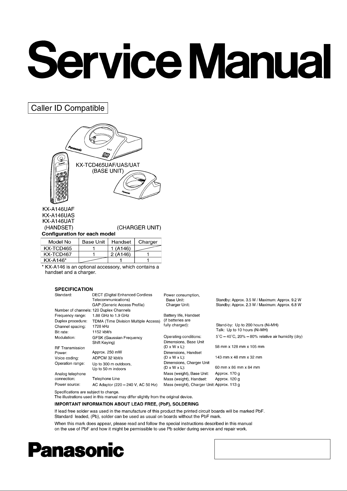
Panasonic KX-TCD465UA, KX-TCD467UA SERVICE MANUAL
ORDER NO. KM40405443C3
Telephone Equipment
KX-TCD465UA
KX-TCD467UA
KX-A146UA
Digital Cordless Answering System
UAF - Metallic Blue Version
UAS - New Silver Version
UAT - Titanium Black Versi on
(for Ukraine)
© 2004 Panasonic Communications Co., Ltd. All
rights reserved. Unauthorized copying and
distribution is a violation of law.
KX-TCD465UA / KX-TCD467UA / KX-A146UA
Note:
Because CONTENTS 5 to 8 are the extracts from the Operating Instructions of this model, they are subject to change without
notice. Please refer to the original Operating Instructions for further information.
CONTENTS
Page Page
1 ABOUT LEAD FREE SOLDER (PbF: Pb free) 4
1.1. Suggested PbF Solder
1.2. How to recognize that Pb Free solder is used
2 FOR SERVICE TECHNICIANS
3 CAUTION
4 BATTERY
4.1. Battery Installation
4.2. Battery Charge
4.3. Battery Life
4.4. Replacing the Batteries
5 LOCATION OF CONTROLS
5.1. Base Unit
5.2. Handset
6 SETTINGS
6.1. Connections
6.2. Ringer Volume
6.3. PIN Code
6.4. Reset
6.5. Key Lock
6.6. R button to use the recall feature
6.7. Pause button for PBX (line/long distance service users)
6.8. Setting Call Restriction
6.9. Cancelling a Restricted Number
6.10. Setting Call BAR
6.11. Selecting the Display Language
6.12. Setting Dialling Mode (Tone/Pulse)
6.13. Setting Flash Time
6.14. Automatic Route Selection
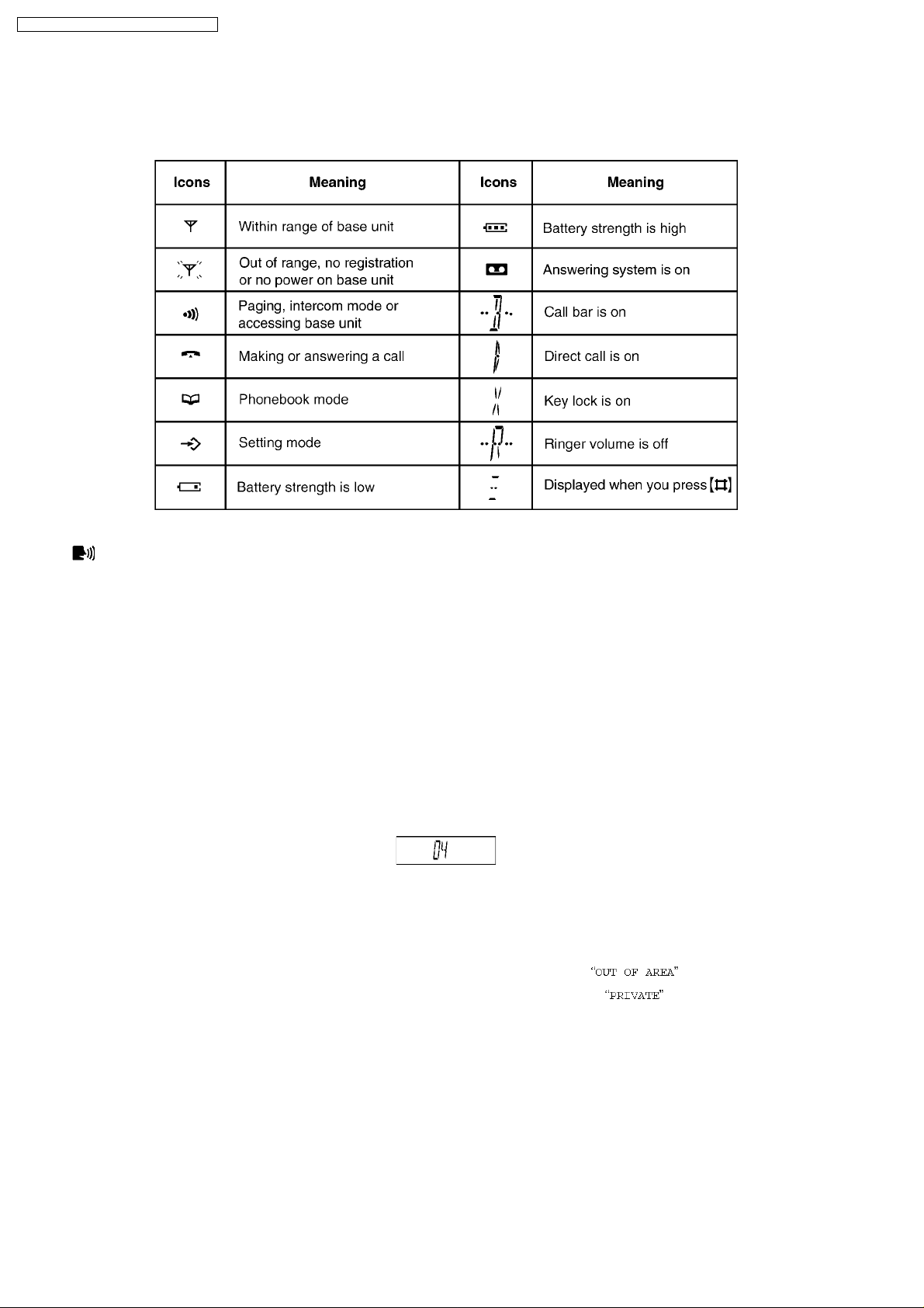
7 DISPLAY
7.1. Handset Display
7.2. Caller ID Display
7.3. Before Requesting Help (Troubleshooting)
8 OPERATIONS
8.1. Turning the Power On/Off
8.2. Setting the Time and Date
8.3. Redialling
10
10
10
11
11
12
13
14
15
15
15
16
16
16
17
17
17
17
20
20
20
21
23
23
23
23
4
5
7
7
8
8
8
9
9
8.4. Phonebook
8.5. Hot Key (Quick Dial)
8.6. Registering a Handset to a Base Unit
8.7. Selecting a Base Unit
8.8. Answering System
9 DISASSEMBLY INSTRUCTIONS
9.1. Base Unit
9.2. Handset
9.3. Charger Unit
10 ASSEMBLY INSTRUCTIONS
10.1. Warning When Constructing the Base Unit
10.2. Processing of Ringer/Charge Terminal Lead
11 TR OUBLESHOOTING GUIDE
11.1. Check Power
11.2. Check Battery Charge
11.3. Check Link
11.4. Check Handset Transmission
11.5. Check Handset Reception
11.6. Check Caller ID
11.7. TAM Voice Prompt Problems
11.8. Bell Reception
12 CHECK PROCEDURE (BASE UNIT)
12.1. Preparation
12.2. PC Setting
12.3. TAM Voice Prompt Download
13 CHECK PROCEDURE (HANDSET)
13.1. Preparation
13.2. PC Setting
14 ADJUSTMENTS (BASE UNIT AND CHARGER UNIT)
14.1. Adjustment (Base Unit)
14.2. Adjustment Standard (Base Unit)
14.3. Adjustment (Charger Unit)
14.4. Adjustment Standard (Charger Unit)
15 ADJUSTMENTS (HANDSET)
15.1. Adjustment (Handset)
15.2. Adjustment Standard (Handset)
24
25
26
27
28
31
31
32
33
34
34
35
36
37
38
39
41
41
41
42
43
44
44
44
45
46
46
46
47
47
50
52
52
53
53
56
2

KX-TCD465UA / KX-TCD467UA / KX-A146UA
16 R F SPECIFICAT ION 57
16.1. Base Unit
16.2. Handset
17 HOW TO CHECK THE HANDSET SPEAKER OR RECEIVER
18 FREQUENCY TABLE (MHz)
19 B LOCK DIAGRAM (BASE UNIT)
20 CIRCUIT OPERATION (BASE UNIT)
20.1. Outline
20.2. Power Supply Circuit
20.3. Telephone Line Interface
20.4. Transmitter/Receiver
20.5. Pulse Dialing
21 B LOCK DIAGRAM (HANDSET)
22 CIRCUIT OPERATION (HANDSET)
22.1. Outline
22.2. Power Supply Circuit/Reset Circuit
22.3. Charge Circuit
22.4. Battery Low/Power Down Detector
22.5. Speakerphone
23 CIRCUIT OPERATION (CHARGER UNIT)
23.1. Power Supply Circuit
24 SIGNAL ROUTE
25 CPU DATA (BASE UNIT)
25.1. IC2 (BBIC)
26 CPU DATA (HANDSET)
26.1. IC1 (BBIC)
27 EEPROM LAYOUT (BASE UNIT)
27.1. Scope
27.2. Introduction
27.3. EEPROM Layout
28 EEPROM LAYOUT (HANDSET)
28.1. Scope
28.2. Introduction
28.3. EEPROM contents
29 HOW TO REPLACE FLAT PACKAGE IC
29.1. Preparation
29.2. Procedure
29.3. Modification Procedure of Bridge
57
57
57
58
59
60
60
61
62
62
62
63
64
64
64
64
64
64
65
65
66
67
67
70
70
72
72
72
72
76
76
76
76
79
79
79
79
30 C ABINET AND ELECTRICAL PARTS LOCATION (BASE UNIT)
31 C ABINET AND ELECTRICAL PARTS LOCATION (HANDSET)
32 C ABINET AND ELECTRICAL PARTS LOCATION (CHARGER
UNIT)
33 ACCESSORIES AND PACKING MATERIALS
33.1. KX-TCD465UAF/UAS/UAT
33.2. KX-TCD467UAF/UAS/UAT
33.3. KX-A146UAF/UAS/UAT
34 TER MINAL GUIDE OF THE ICs, TR ANSISTOR S AND DIODES
34.1. Base Unit
34.2. Handset
34.3. Charger Unit
35 REPLACEMENT PARTS LIST
35.1. Base Unit
35.2. Handset
35.3. Charger Unit
35.4. Accessories and Packing Materials
35.5. Fixtures and Tools
35.6. Memo
36 FOR SCHEMATIC DIAGRAM
36.1. Base Unit (SCHEMATIC DIAGRAM (BASE UNIT))
36.2. Handset (SCHEMATIC DIAGRAM (HANDSET))
36.3. Charger Unit (SCHEMATIC DIAGRAM (CHARGER UNIT))
37 SCHEMATIC DIAGRAM (BASE UNIT)
38 SCHEMATIC DIAGRAM (HANDSET)
39 SCHEMATIC DIAGRAM (CHARGER UNIT)
40 CIRCUIT BOARD (BASE UNIT)
40.1. Component View
40.2. Flow Solder Side View
41 CIRCUIT BOARD (HANDSET)
41.1. Component View
41.2. Flow Solder Side View
42 CIRCUIT BOARD (CHARGER UNIT)
42.1. Component View
42.2. Flow Solder Side View
100
101
101
102
103
103
103
80
81
82
83
83
84
85
86
86
86
86
87
87
89
90
90
91
92
93
93
93
93
94
96
98
99
99
3
KX-TCD465UA / KX-TCD467UA / KX-A146UA
1 ABOUT LEAD FREE SOLDER (PbF: Pb free)
Note:
In the information below, Pb, the symbol for lead in the periodic table of elements, will refer to standard solder or solder that
contains lead.
We will use PbF solder when discussing the lead free solder used in our manufacturing process which is made from Tin (Sn),
Silver (Ag), and Copper (Cu).
This model, and others like it, manufactured using lead free solder will have PbF stamped on the PCB. For service and repair
work we suggest using the same type of solder although, with some precautions, standard Pb solder can also be used.
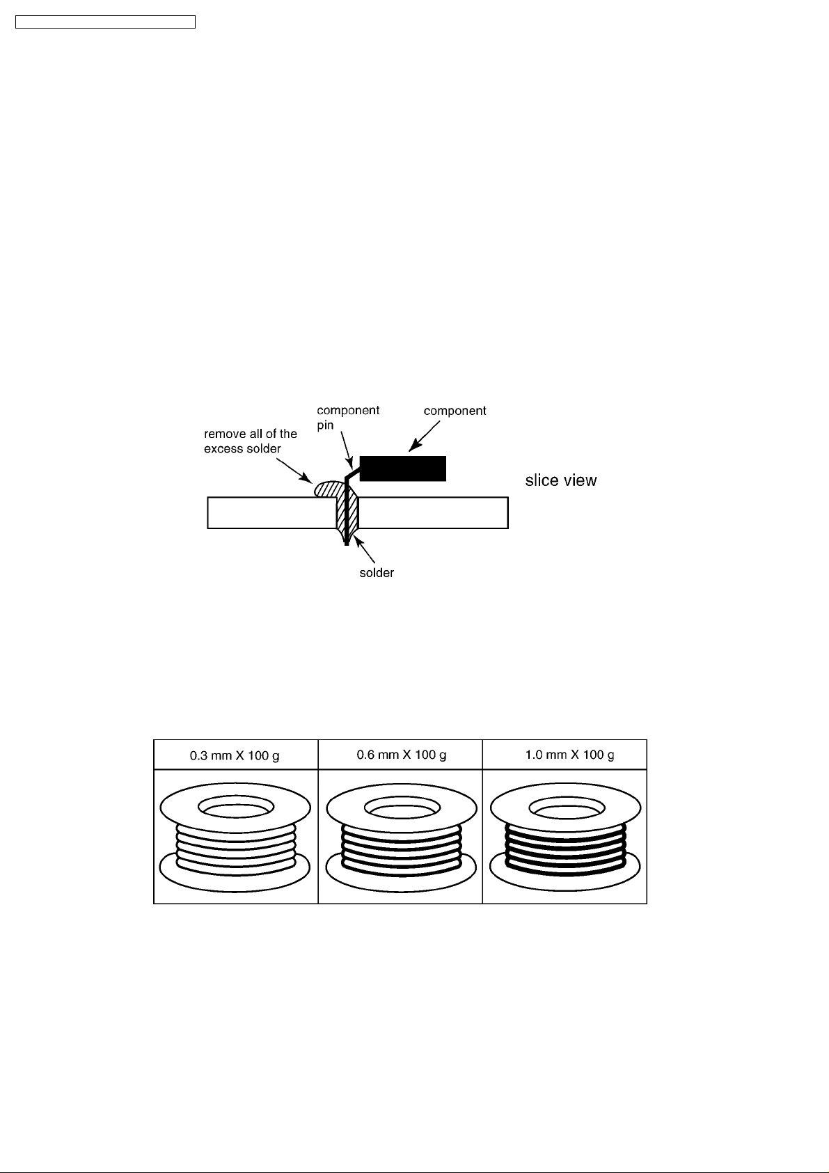
Caution
· PbF solder has a melting point that is 50 °F ~70°F (30 °C ~ 40 °C) higher than Pb solder. Please use a soldering iron with
temperature control and adjust it to 700 °F ± 20 °F(370 °C ± 10 °C). In case of using high temperature soldering iron, please
be careful not to heat too long.
· PbF solder will tend to splash if it is heated much higher than its melting point, approximately 1100 °F (600 °C).
· If you must use Pb solder on a PCB manufactured using PbF solder, remove as much of the original PbF solder as possible
and be sure that any remaining is melted prior to applying the Pb solder.
· When applying PbF solder to double layered boards, please check the component side for excess which may flow onto the
opposite side (See the figure below).
1.1. Suggested PbF Solder
There are several types of PbF solder available commercially. While this product is manufactured using Tin, Silver, and Copper
(Sn+Ag+Cu), you can also use Tin and Copper (Sn+Cu) or Tin, Zinc, and Bismuth (Sn+Zn+Bi). Please check the
manufacturer’s specific instructions for the melting points of their products and any precautions for using their product with other
materials.
The following lead free (PbF) solder wire sizes are recommended for service of this product: 0.3 mm, 0.6 mm and 1.0 mm.
4
1.2. How to recognize that Pb Free solder is used
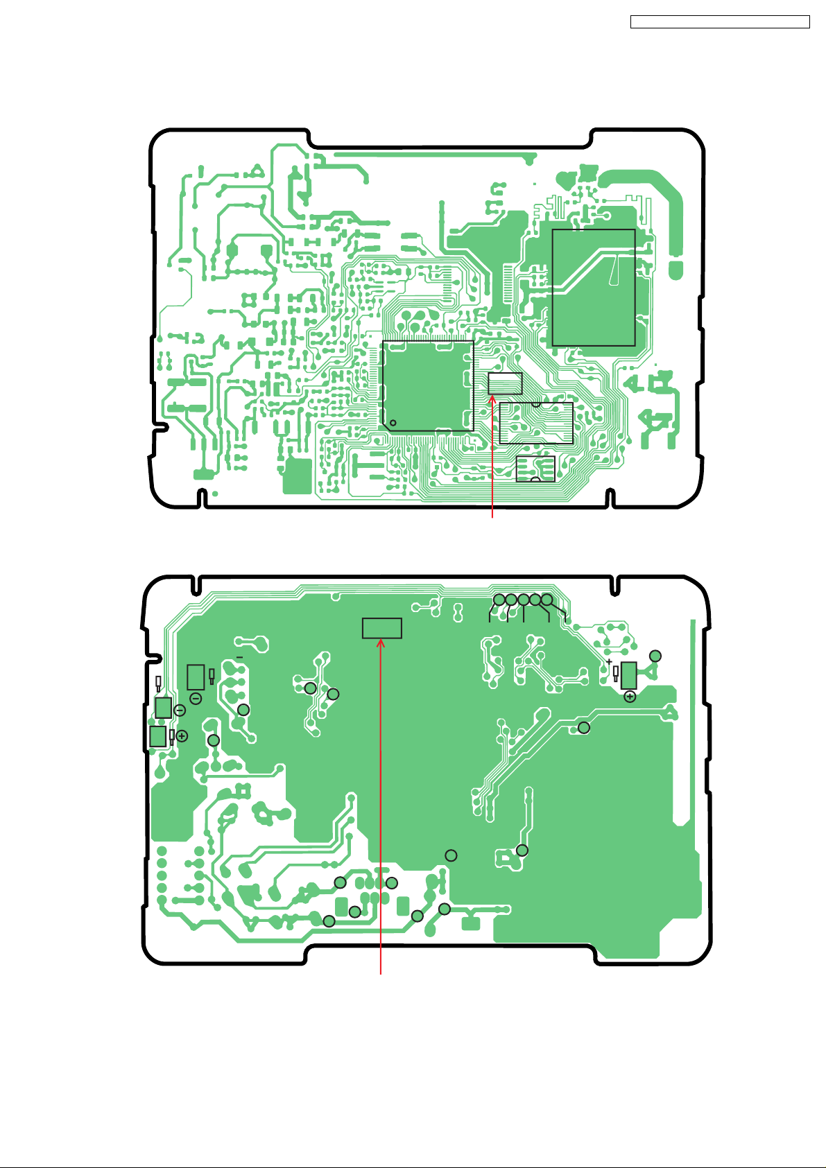
1.2.1. Base Unit PCB
KX-TCD465UA / KX-TCD467UA / KX-A146UA
108
109
IC8
144
(Component View)
PbF
73
72
37
36
Marked
PbF
1
16
8
SDAVDD
SCL
IC7
IC4
MODE
GND
1
28
IC9
11
32
17
45
1
J105J102J104J103J101
18
CHARGE
TP202
TP6
TP5
TP201
TP7
TP3
TP4
TP8
TP2
6
4
2
TP1
5
1
Marked
(Flow Solder Side View)
Note:
The location of the “PbF” mark is subject to change without notice.
TP10
TP9
TP106
TP11
CHARGE
TP15
TP13
5
KX-TCD465UA / KX-TCD467UA / KX-A146UA
1.2.2. Handset PCB
Marked
MIC
INT
30
31
IC1
50
51
8
1
IC2
5
4
1
100
81
80
11 18
PbF
281
IC3
(Component View)
Marked
36
1
CN2
PbF
LED101
LED102 LED103
LEFT
RIGHT
TALK
UP
POWER
BOOK
REDIAL
PROG
R
0
#
7
LED106
8
LED105
9
4
5
LED107
LED104
1
LED108
SP_
2
36
DOWN
CAN
(Flow Solder Side View)
Note:
The location of the “PbF” mark is subject to change without notice.
1.2.3. Charger Unit PCB
J1
D1
PbF
Marked
(Component View) (Flow Solder Side View)
Note:
The location of the “PbF” mark is subject to change without notice.
TP1
TP2
R1
R2
TP3
TP4
PbF
Marked
6

KX-TCD465UA / KX-TCD467UA / KX-A146UA
2 FOR SERVICE TECHNICIANS
ICs and LSIs are vulnerable to static electricity.
When repairing, the following precautions will help prevent recurring malfunctions.
1. Cover the plastic parts boxes with aluminum foil.
2. Ground the soldering irons.
3. Use a conductive mat on the worktable.
4. Do not touch IC or LSI pins with bare fingers.
3 CAUTION
Danger of explosion if battery is incorrectly replaced. Replace only with the same or equivalent type recommended by the
manufacturer.
Dispose of used batteries according to the manufacture’s Instructions.
7
KX-TCD465UA / KX-TCD467UA / KX-A146UA
4 BATTERY
4.1. Battery Installation
1. Insert the batteries negative (-) terminal first.
2. Close the battery cover.
Note:
· Use only rechargeable P03P (Ni-MH)/P03H (Ni-Cd) batteries.
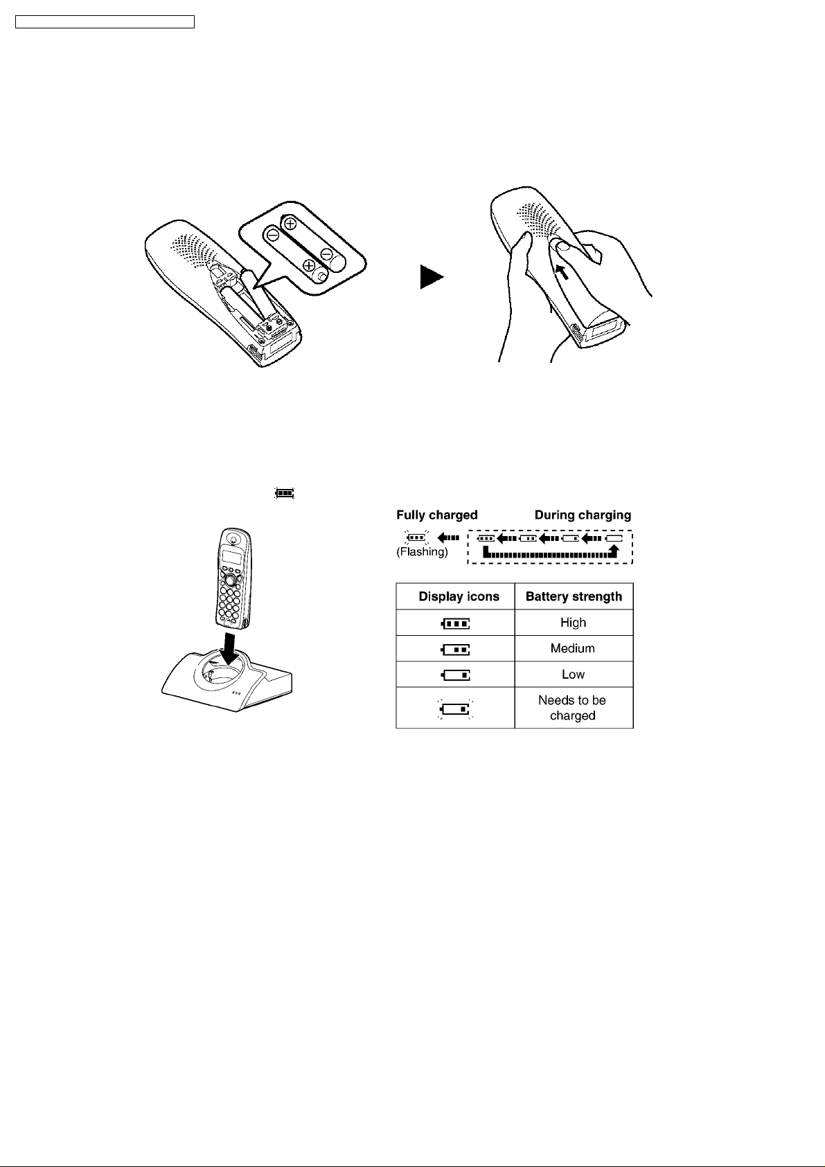
4.2. Battery Charge
Place the handset on the base unit for about 7 hours before initial use.
When the batteries are fully charged,
Note:
· Clean the charge contacts of the handset and base unit with a soft, dry cloth, otherwise the batteries may not charge
properly. Clean if the unit is exposed to grease, dust or high humidity.
· If the handset is turned off, it will be turned on automatically when it is placed on the base unit.
Note for Service:
· The battery strength may not be indicated correctly if the battery is disconnected and connected again, even after it is fully
charged.
· In that case, by recharging the battery as mentioned above, you will get a correct indication of the battery strength.
flashes. When charging, the battery icon is shown as follows.
8
KX-TCD465UA / KX-TCD467UA / KX-A146UA
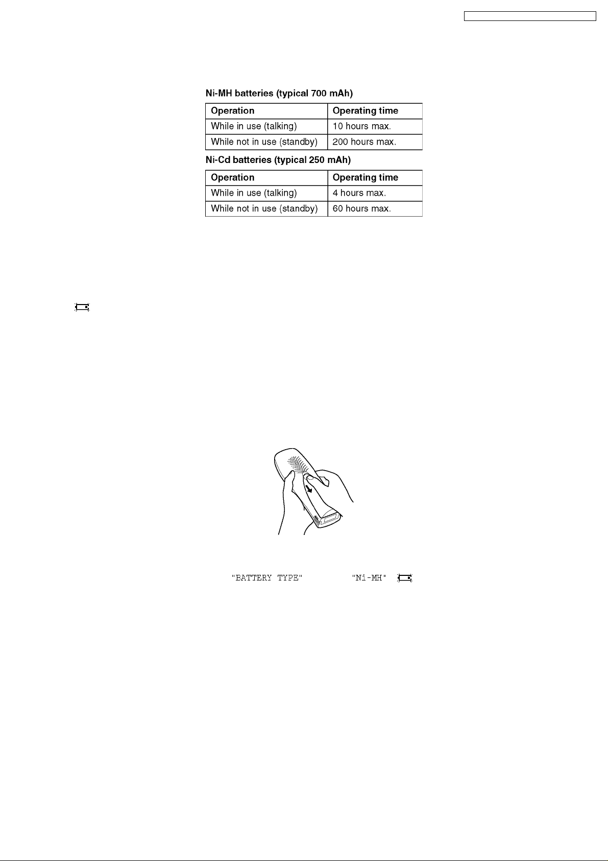
4.3. Battery Life
After your Panasonic batteries are fully charged, you can expect the following performance:
Note:
· The included batteries are Ni-MH batteries.
· Battery operating time may be shortened depending on usage conditions and ambient temperature.
4.4. Replacing the Batteries
If flashes even when the handset batteries have been fully charged, both batteries must be replaced.
Important:
· Please use only the Panasonic batteries P03P(Ni-MH)/P03H(Ni-Cd).
· Use only rechargeable batteries. If you install non-rechargeable batteries and start charging, the batteries may leak
electrolyte.
· Do not mix old and new batteries.
· Use only 2 nickel metal hydride (Ni-MH) batteries or 2 nickel cadmium (Ni-Cd) batteries. Do not mix battery types.
· Ensure that the correct battery type is selected.
1. Press the notch on the cover firmly and slide it in the direction of the arrow.
2. Remove the batteries positive (+) terminal first. Replace both batteries.
Note for Service:
· When Ni-Cd batteries are fitted with the
even if the handset is on the cradle for avoiding overcharge.
setting in , icon might disappear and stop charging
9
KX-TCD465UA / KX-TCD467UA / KX-A146UA
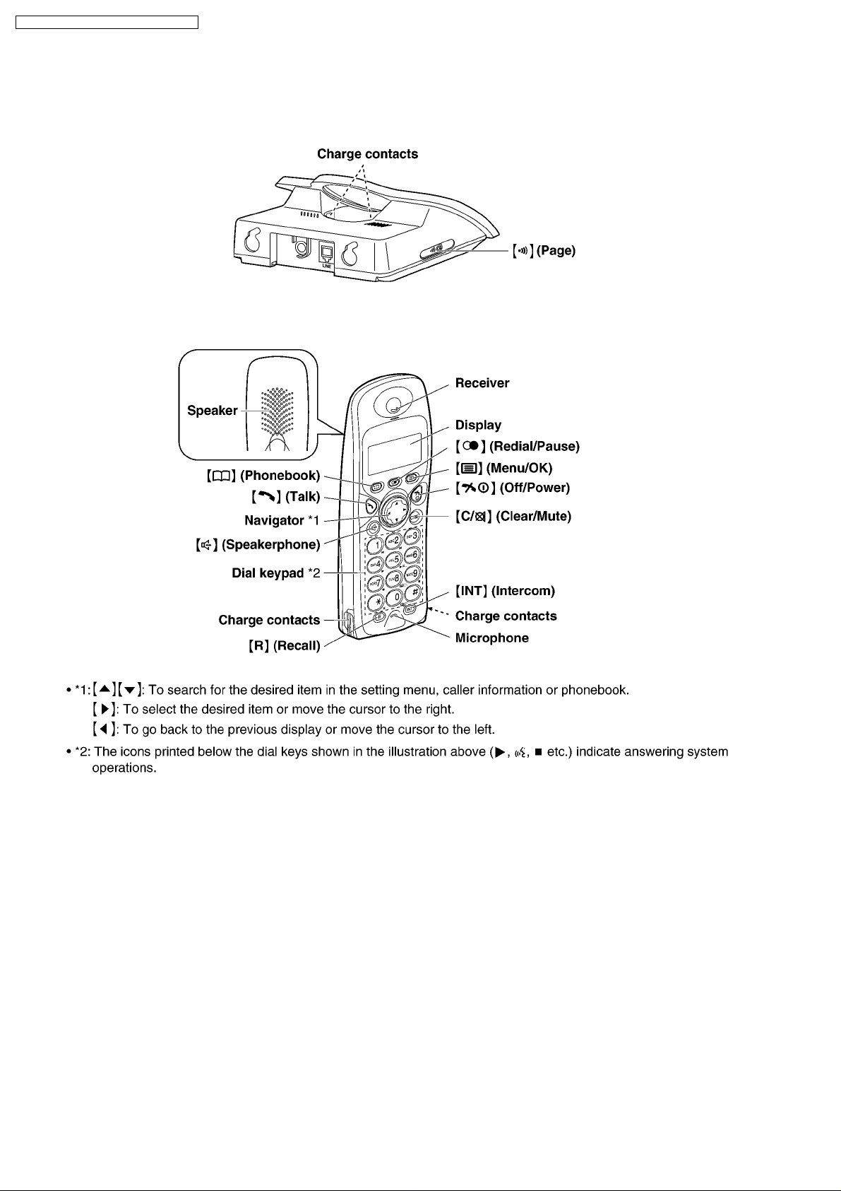
5 LOCATION OF CONTROLS
5.1. Base Unit
5.2. Handset
10
KX-TCD465UA / KX-TCD467UA / KX-A146UA
6 SETTINGS
Important information
General
· Use only the power supply included with this products.
· Do not connect the AC adaptor to any AC outlet other than a standard 220-240 V AC outlet.
· This product is unable to make calls when:
−
− The portable handset batteries need recharging or have failed.
− −
−
− There is a power failure.
− −
−
− The key lock feature is turned on.
− −
−
− The call bar feature is turned on (only numbers stored as emergency numbers can be called).
− −
· Do not open the base unit or handset (other than to change the batteries).
· This product should not be used near emergency/intensive care medical equipment and should not be used by people with
pacemakers.
· Care should be taken that objects do not fall onto, and liquids are not spilled into, the unit. Do not subject this product to
excessive smoke, dust, mechanical vibration or shock.
Environment
· Do not use this product near water.
· This product should be kept away from heat sources such as radiators, cookers, etc. It should also not be placed in rooms
where the temperature is less than 5 °C or greater than 40 °C.
· The AC adaptor is used as the main disconnect device. Ensure that the AC outlet is located/installed near the unit and is
easily accessible.
Location
For maximum distance and noise-free operation, place your base unit:
- Away from electrical appliances such as TVs, radios, personal computers or other phones.
- In a convenient, high and central location.
Warning:
· To prevent the risk of electrical shock, do not expose this product to rain or any other type of moisture.
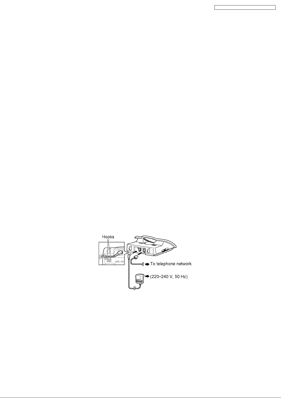
6.1. Connections
6.1.1. Base Unit
Note:
· If the handset is not charged, you cannot make or answer calls.
· Never install telephone wiring during a lightning storm.
· The AC adaptor must remain connected at all times. (It is normal for the adaptor to feel warm during use.)
· Use only the AC adaptor PQLV19CEZ.
11
KX-TCD465UA / KX-TCD467UA / KX-A146UA
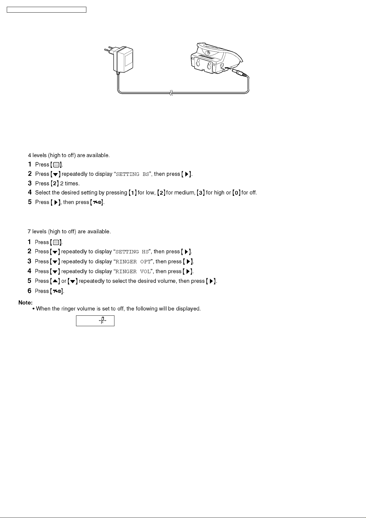
6.1.2. Charger Unit
· The AC adaptor must remain connected at all times (It is normal for the adaptor to feel warm during use).
· Use only the AC adaptor PQLV200CEZ.
6.2. Ringer Volume
6.2.1. Base Unit
6.2.2. Handset
12
6.3. PIN Code
6.3.1. Base Unit
For Service Hint:
*: If the current 4-digit PIN is forgotten, press
6.3.2. Handset
KX-TCD465UA / KX-TCD467UA / KX-A146UA
and you will be able to enter new PIN.
For Service Hint:
*: If the current 4-digit PIN is forgotten, press
and you will be able to enter new PIN.
13
KX-TCD465UA / KX-TCD467UA / KX-A146UA
6.4. Reset
6.4.1. Base Unit
Note:
· The emergency number setting will not be reset.
Base Unit Initial Settings
Function Initial Setting Remarks (selectable options)
Base Unit Ringer Volume 2 1 to 3, OFF
Ringer Mode All Handsets All Handsets/Specific Handset No.
Number of Rings (Ringer Mode) 3 Up to 6 rings
Number of Rings (TAM) AUTO 2to7,AUTO
Dialling Mode Pulse Tone/Pulse
Flash Timing 700 msec 100/700/200 msec
Pause Length 3 seconds 3 seconds/5 seconds
Call Restricted Handsets All Clear Each Handset can be set individually.
Call Restriction Numbers All Clear Up to 10 numbers (up to 8 digits)
4-Digit Base Unit PIN 0000 ARS Setting OFF ON/OFF
Carrier Code All Clear Up to 5 (up to 7 digits)
Area Code All Clear Up to 25 (up to 5 digits)
Relation of Area Code All Area Code to Carrier Code 1 1to5
Caller ID All Clear Up to 50 different callers
6.4.2. Handset
Note:
· Phonebook entries will not be erased.
· The battery type setting will not be reset.
14
KX-TCD465UA / KX-TCD467UA / KX-A146UA
Handset Initial Settings
Function Initial Setting Remarks (selectable options)
Select Base Unit Auto Time Alarm Mode OFF OFF/Once/Daily
Alarm Time Clear Handset Ringer Volume 6 1 to 6, OFF
Handset External Ringer Pattern 1 20 patterns
Handset Internal Ringer Pattern 1 20 patterns
Handset Paging Tone Pattern 1 20 patterns
Handset Alarm Tone Pattern 1 20 patterns
Key Tone ON ON/OFF
Call Waiting Tone ON ON/OFF
Range Warning Alarm OFF OFF/ON
Battery Low Alarm ON ON/OFF
Standby Mode Display Clock Clock/OFF/Base No./Handset No.
Talk Mode Display Talk Time Talk Time/Phone No.
Display Language English 10 languages
Call BAR OFF OFF/ON
Direct Call Mode OFF OFF/ON
Direct Call Number Clear Up to 24 digits
4-Digit Handset PIN 0000 Auto Talk OFF OFF/ON
Redial Memory All Clear Up to 10 numbers (up to 24 digits)
Handset Receiver Volume 2 1to3
Handset Speaker Volume 3 1to6
6.5. Key Lock
The dial keys can be locked so that no calls can be made. Only incoming calls will be accepted while key lock is on.
Note:
· Emergency calls cannot be made until key lock is turned off.
· Key lock is turned off when the handset is turned off.
6.6. R button to use the recall feature
6.7. Pause button for PBX (line/long distance service users)
A pause is sometimes required when making calls using a PBX or long distance service.
15
KX-TCD465UA / KX-TCD467UA / KX-A146UA
6.8. Setting Call Restriction
You can restrict selected handsets from dialling certain phone numbers. You can assign up to 10 phone numbers to be
restricted per handset. If a restricted number is dialled, the call will not be connected and the restricted number will flash on the
display. For example, storing an area code will prevent a handset from dialling a long distance call.
6.9. Cancelling a Restricted Number
6.10. Setting Call BAR
This feature prohibits making outside calls. When call bar is turned on, only intercom calls and emergency calls can be made.
16
KX-TCD465UA / KX-TCD467UA / KX-A146UA
6.11. Selecting the Display Language
10 display languages are available.
Note:
· If you select a language you cannot read, reset the handset to its default settings. Refer to Handset (P.14) in “Reset“.
6.12. Setting Dialling Mode (Tone/Pulse)
6.13. Setting Flash Time
6.14. Automatic Route Selection
17
KX-TCD465UA / KX-TCD467UA / KX-A146UA
6.14.1. Storing Carrier Codes
6.14.2. Storing Area Codes
6.14.3. Assigning Carrier Codes to Area Codes
18

6.14.4. Automatic Route Selection On/Off
KX-TCD465UA / KX-TCD467UA / KX-A146UA
19
KX-TCD465UA / KX-TCD467UA / KX-A146UA
7 DISPLAY
7.1. Handset Display
For Service Hint:
icon will be displayed if the unit took a signal from Telephone Company as a Voice Message signal.
In that case, press the left button of the Navigator Key for a while.
7.2. Caller ID Display
Important:
This unit is European Caller ID compatible and does not support Russian Caller ID (AOH) service. To display the caller’s phone
number, you must subscribe to Caller ID service. After subscribing to Caller ID, this unit will display caller information.
How Caller ID is displayed
The unit will display the calling party’s phone number after the first ring. You can view the caller information of the last 50
different callers.
When new calls have been received, the display will show the number of new calls.
The number of new calls will be cleared after viewing all caller information.
Example: 4 new calls have been received.
Note:
· When you receive a call from the same phone number you stored with a name in the phonebook, the display will show the
stored name.
· If the unit is connected to a PBX system, you may not receive the caller information.
· When the caller dialled from an area which does not provide Caller ID service,
· When the caller requested not to send caller information, either no information or
· The display will not show caller information while using the handset for an intercom call. However, the caller information will
be stored.
will be displayed.
will be displayed.
20
KX-TCD465UA / KX-TCD467UA / KX-A146UA
7.3. Before Requesting Help (Troubleshooting)
If you still have difficulties after following the instructions in this section, disconnect the AC adaptor and turn off the handset,
then reconnect the AC adaptor and turn on the handset.
Cross Reference:
(*1) Registering a Handset to a Base Unit (P.26).
(*2) Setting Call BAR (P.16).
(*3) Setting Call Restriction (P.16).
(*4) Key Lock (P.15).
(*5) Setting Dialling Mode (Tone/Pulse) (P.17).
(*6) Ringer Volume (P.12).
(*7) Turning the Power On/Off (P.23).
(*8) Battery Installation (P.8).
(*9) Battery Charge (P.8).
21
KX-TCD465UA / KX-TCD467UA / KX-A146UA
Cross Reference:
(*10) Battery Charge (P.8).
(*11) Replacing the Batteries (P.9).
(*12) Caller ID Display (P.20).
(*13) PIN Code (P.13).
(*14) Erasing All Messages (P.28).
(*15) Remote Operation (P.29).
22
8 OPERATIONS
8.1. Turning the Power On/Off
8.2. Setting the Time and Date
KX-TCD465UA / KX-TCD467UA / KX-A146UA
Note:
· If a power failure occurs, set the time and date again.
8.3. Redialling
8.3.1. Making a Call Using the Redial List
The last 10 phone numbers dialled are stored in the redial list.
8.3.2. Redialling the Last Number Dialled
23

KX-TCD465UA / KX-TCD467UA / KX-A146UA
8.4. Phonebook
8.4.1. Storing Phone Numbers and Names
Up to 20 phone numbers can be stored in the phonebook for quick access.
24
8.4.2. Storing a Number from the Caller ID List into the Phonebook
8.4.3. Storing a Number from the Redial List into the Phonebook
KX-TCD465UA / KX-TCD467UA / KX-A146UA
8.5. Hot Key (Quick Dial)
Note:
· The number erased from a hot key will not be erased from the phonebook.
25
KX-TCD465UA / KX-TCD467UA / KX-A146UA
8.6. Registering a Handset to a Base Unit
8.6.1. Cancelling a Handset
26
8.6.2. Cancelling a Base Unit
8.7. Selecting a Base Unit
KX-TCD465UA / KX-TCD467UA / KX-A146UA
27
KX-TCD465UA / KX-TCD467UA / KX-A146UA
8.8. Answering System
8.8.1. Listening to Messages
8.8.2. Erasing All Messages
28
KX-TCD465UA / KX-TCD467UA / KX-A146UA
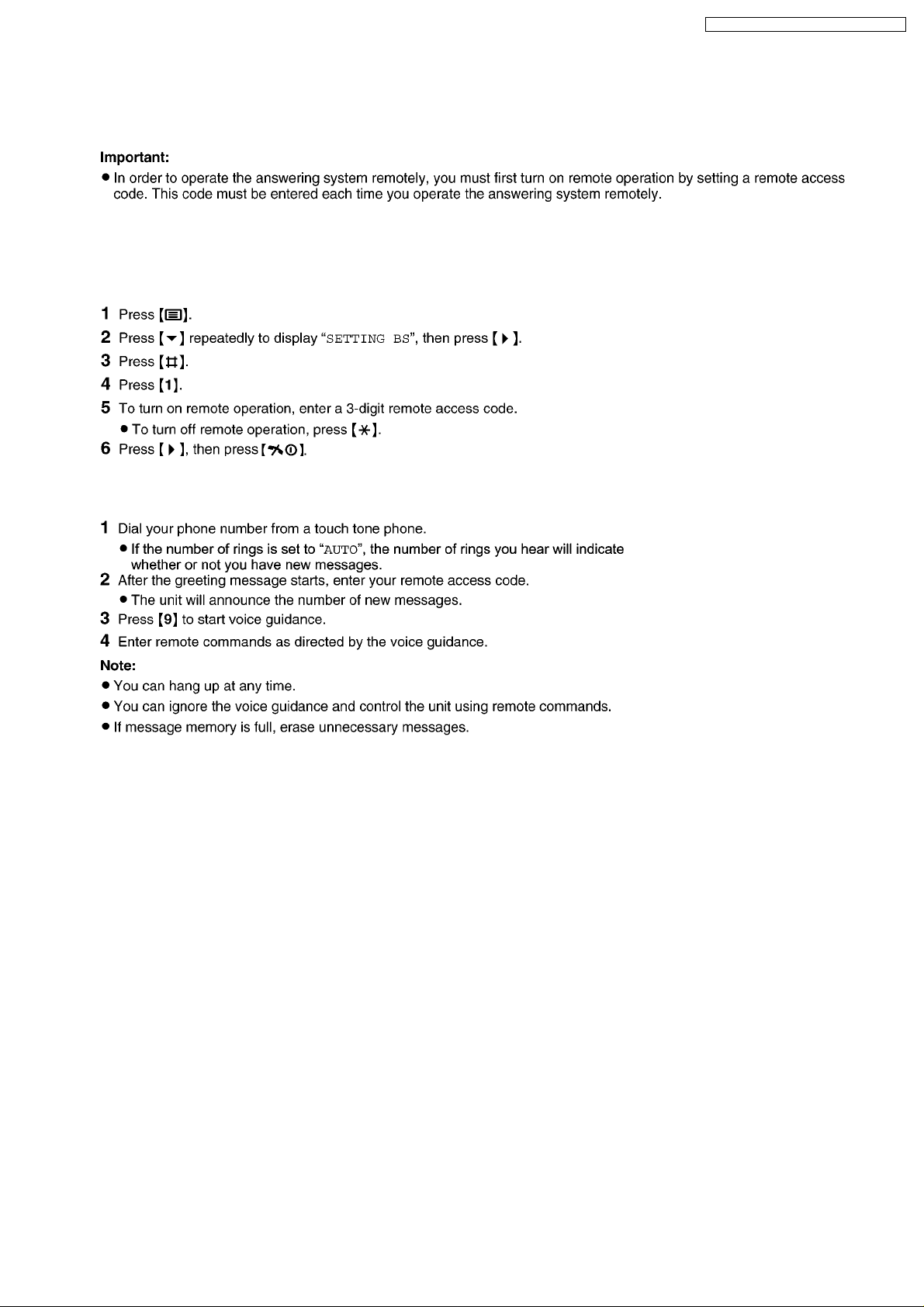
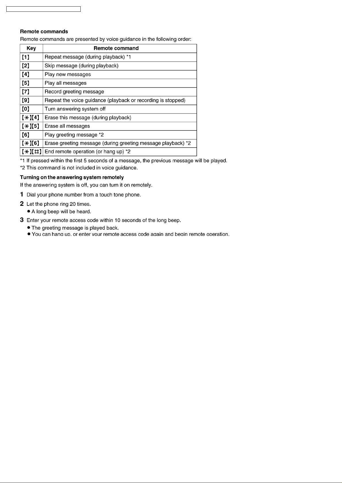
8.8.3. Remote Operation
Using a touch tone phone, you can call your phone number from outside and access the unit to listen to messages or change
answering system settings. The unit’s voice guidance will prompt you to press certain dial keys to perform different operations.
Turning remote operation on/off
A 3-digit remote access code must be entered when operating the answering system remotely. This code prevents
unauthorized parties from listening to your messages remotely. After you store your remote access code, remote operation
is possible.
Using the answering system remotely
During remote operation, the unit’s voice guidance will prompt you to press certain key to operate the answering system.
29
KX-TCD465UA / KX-TCD467UA / KX-A146UA
30
 Loading...