

Panasonic KX-TC1205RUW, KX-TC1205RUS, KX-TC1205RUB, KX-TC1205RUF User Manual
ORDER NO. KM40204852C3
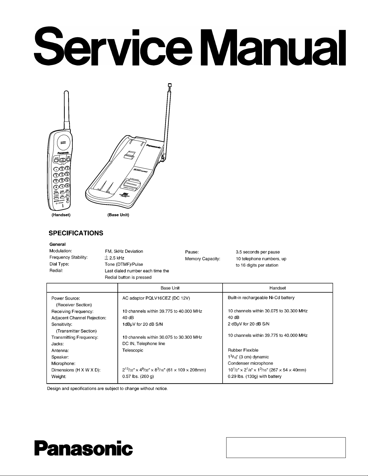
Telephone Equipment
KX-TC1205RUB
KX-TC1205RUW
KX-TC1205RUS
KX-TC1205RUF
Cordless Phone
Black Version
White Version
Silver Version
Blue Version
(for Russia)
© 2002 Kyushu Matsushita Electric Co., Ltd. All
rights reserved. Unauthorized copying and
distribution is a violation of law.
KX-TC1205RUB / KX-TC1205RUW / KX-TC1205RUS / KX-TC1205RUF
CONTENTS
Page Page
1 BATTERY 4
1.1. Recharge
1.2. Battery information
2 BATTERY REPLACEMENT
3 LOCATION OF CONTROLS
3.1. Base Unit
3.2. Handset
4 CONNECTION
4.1. Adding Another Phone
5 OPERATIONS
5.1. Making Calls
5.2. Answering Calls
5.3. Storing Phone Numbers in Memory
5.4. Storing a Phone Number in the DIRECT Button
5.5. Dialing a Stored Number
5.6. Dialing a Stored Number in the DIRECT Button
5.7. FLASH Button
6 DISASSEMBLY INSTRUCTIONS
7 TROUBLESHOOTING GUIDE
7.1. Check Power
7.2. Bell Reception
7.3. Check Battery Charge
7.4. Check Link
7.5. Check Handset Transmission
7.6. Check Handset Reception
10
10
10
11
11
12
12
13
14
16
17
18
19
20
22
22
8 ADJUSTMENTS (BASE UNIT)
4
4
5
6
6
6
7
9
8.1. Test Mode Flow Chart (Base Unit)
8.2. How to change the channel
8.3. Adjustment
8.4. Adjustment Standard (Base Unit)
9 ADJUSTMENTS (HANDSET)
9.1. Test Mode Flow Chart (Handset)
9.2. How to change the channel
9.3. Adjustment
9.4. Adjustment Standard (Handset)
10 R F SPECIFICAT ION
10.1. Base Unit
10.2. Handset
11 HOW TO CHECK THE HANDSET SPEAKER
12 FREQUENCY TABLE (MHz)
13 EXPLANATION OF CPU DATA COMMUNICATION
13.1. STAND-BY -> TALK, TALK -> STAND-BY
13.2. Ringing
13.3. Changing the Channel
13.4. Ports for transmitting and receiving of data
13.5. Waveform of DATA used for cordless transmission and
reception
14 BLOCK DIAGRAM (BASE UNIT)
15 BLOCK DIAGRAM (HANDSET)
16 CIRCUIT OPERATION
23
23
24
24
25
26
26
27
27
28
30
30
30
30
31
32
32
33
34
35
35
36
37
38
2

16.1. Outline 38
16.2. Power Supply Circuit
16.3. Reset Circuit (Base Unit)
16.4. Charge Circuit
16.5. Telephone Line Interface
16.6. Transmitter/Receiver
16.7. Signal Route
17 CIRCUIT OPERATION (HANDSET)
17.1. Reset Circuit (Handset)
17.2. Battery Low / Power Down Detector
18 CP U DATA (Base Unit)
18.1. IC2
19 CP U DATA (Handset)
19.1. IC2
20 HOW TO REPLACE FLAT PACKAGE IC
20.1. Preparation
20.2. Procedure
20.3. Modification Procedure of Bridge
21 CABINET AND ELECTRICAL PARTS LOCATION (BASE UNIT)
22 CABINET AND ELECTRICAL PARTS LOCATION (HANDET)
KX-TC1205RUB / KX-TC1205RUW / KX-TC1205RUS / KX-TC1205RUF
23 ACCESSORIES AND PACKING MATERIALS
24 REPLACEMENT PARTS LIST
39
40
41
41
42
44
45
45
46
47
47
48
48
49
49
49
49
24.1. Base Unit
24.2. Handset
24.3. ACCESSORIES AND PACKING MATERIALS
25 FOR SCHEMATIC DIAGRAM
25.1. Base Unit (SCHEMATIC DIAGRAM (Base Unit))
25.2. Handset (SCHEMATIC DIAGRAM (Handset))
26 SCHEMATIC DIAGRAM (Base Unit)
26.1. Base Unit
26.2. RF Unit (Base Unit)
27 SCHEMATIC DIAGRAM (Handset)
27.1. Handset
27.2. RF Unit (Handset)
28 CIRCUIT BOARD (Base Unit)
28.1. Component View
28.2. Flow Solder Side View
29 CIRCUIT BOARD (Handset)
29.1. Component View
50
29.2. Flow Solder Side View
51
52
53
53
56
58
59
59
59
60
60
61
62
62
63
65
65
66
67
67
68
3

KX-TC1205RUB / KX-TC1205RUW / KX-TC1205RUS / KX-TC1205RUF
1 BATTERY
1.1. Recharge
1.2. Battery information
4
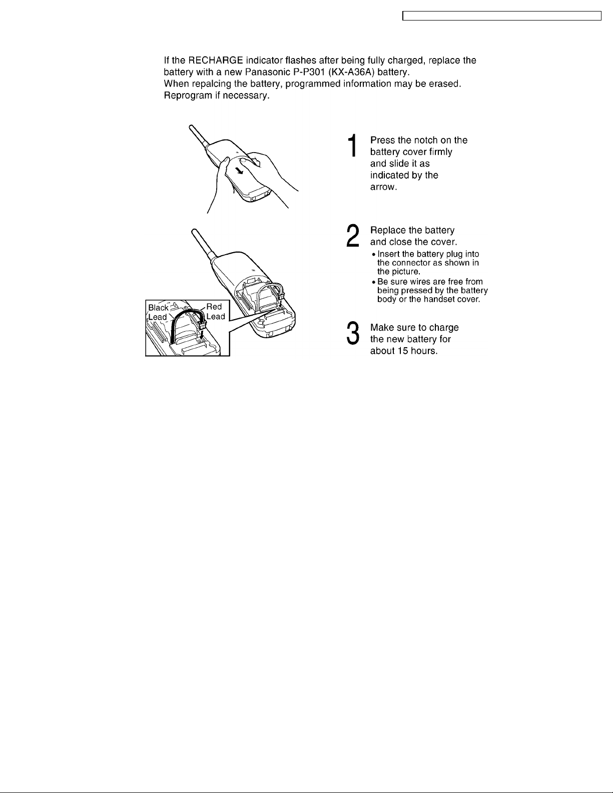
2 BATTERY REPLACEMENT
KX-TC1205RUB / KX-TC1205RUW / KX-TC1205RUS / KX-TC1205RUF
5
KX-TC1205RUB / KX-TC1205RUW / KX-TC1205RUS / KX-TC1205RUF
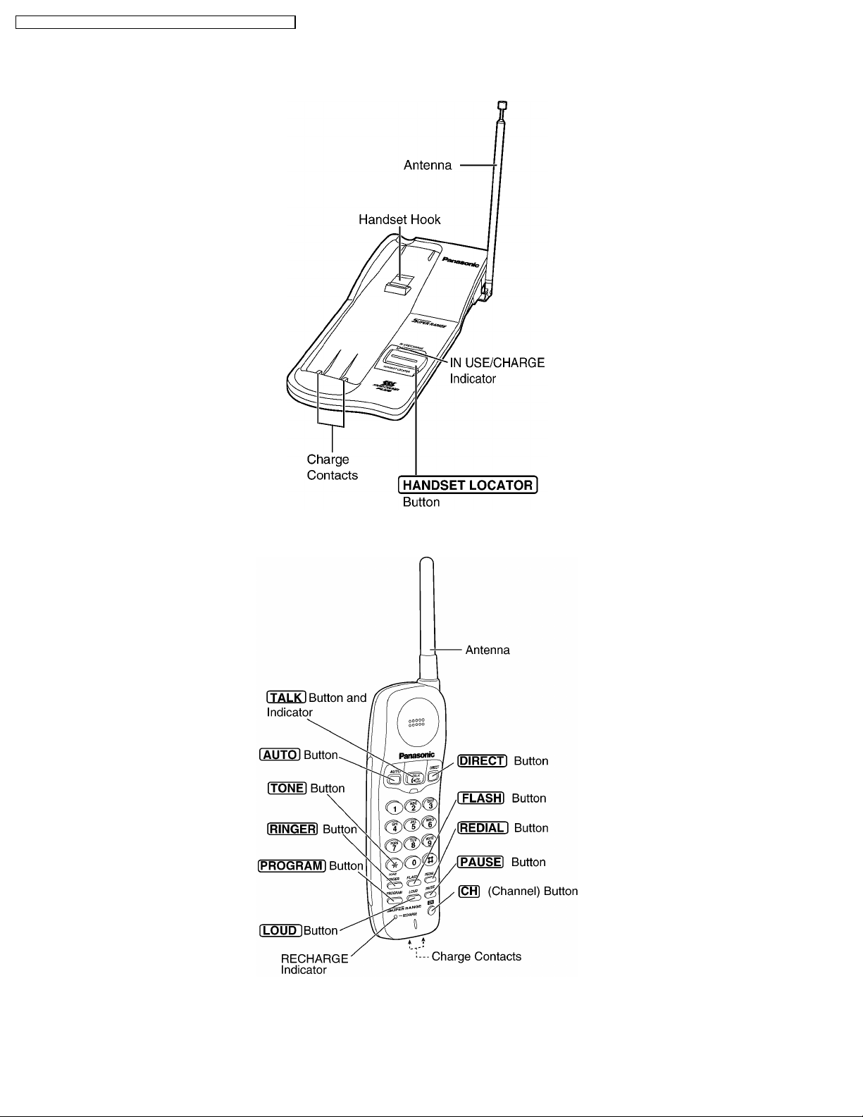
3 LOCATION OF CONTROLS
3.1. Base Unit
3.2. Handset
6
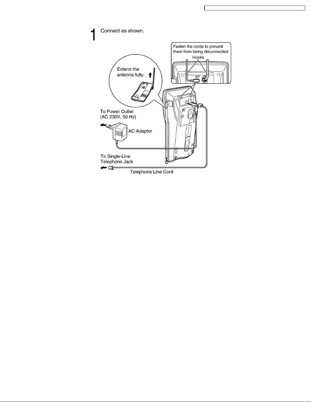
4 CONNECTION
KX-TC1205RUB / KX-TC1205RUW / KX-TC1205RUS / KX-TC1205RUF
• • USE ONLY WITH Panasonic AC ADAPTOR PQLV16CEZ.
• • The AC adaptor must remain connected at all times.
(It is normal for the adaptor to feel warm during use.)
• • When more than one unit is used, the units may interfere with each other. To prevent or reduce interference, please leave
ample space between the base units.
7

KX-TC1205RUB / KX-TC1205RUW / KX-TC1205RUS / KX-TC1205RUF
8
KX-TC1205RUB / KX-TC1205RUW / KX-TC1205RUS / KX-TC1205RUF
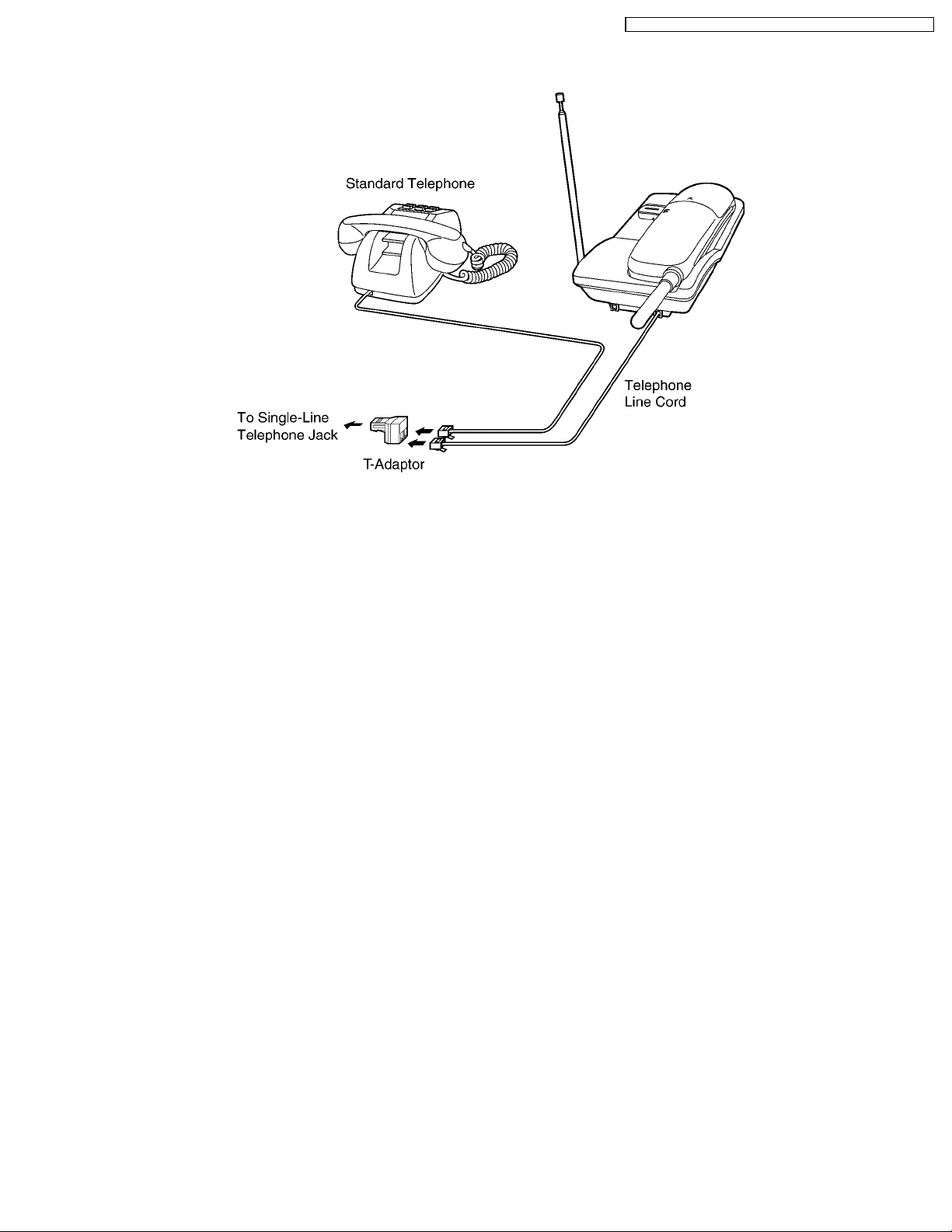
4.1. Adding Another Phone
This unit will not function during a power failue. To connect a standard telephone on the same line, use a telephone T-adaptor.
9
KX-TC1205RUB / KX-TC1205RUW / KX-TC1205RUS / KX-TC1205RUF
5 OPERATIONS
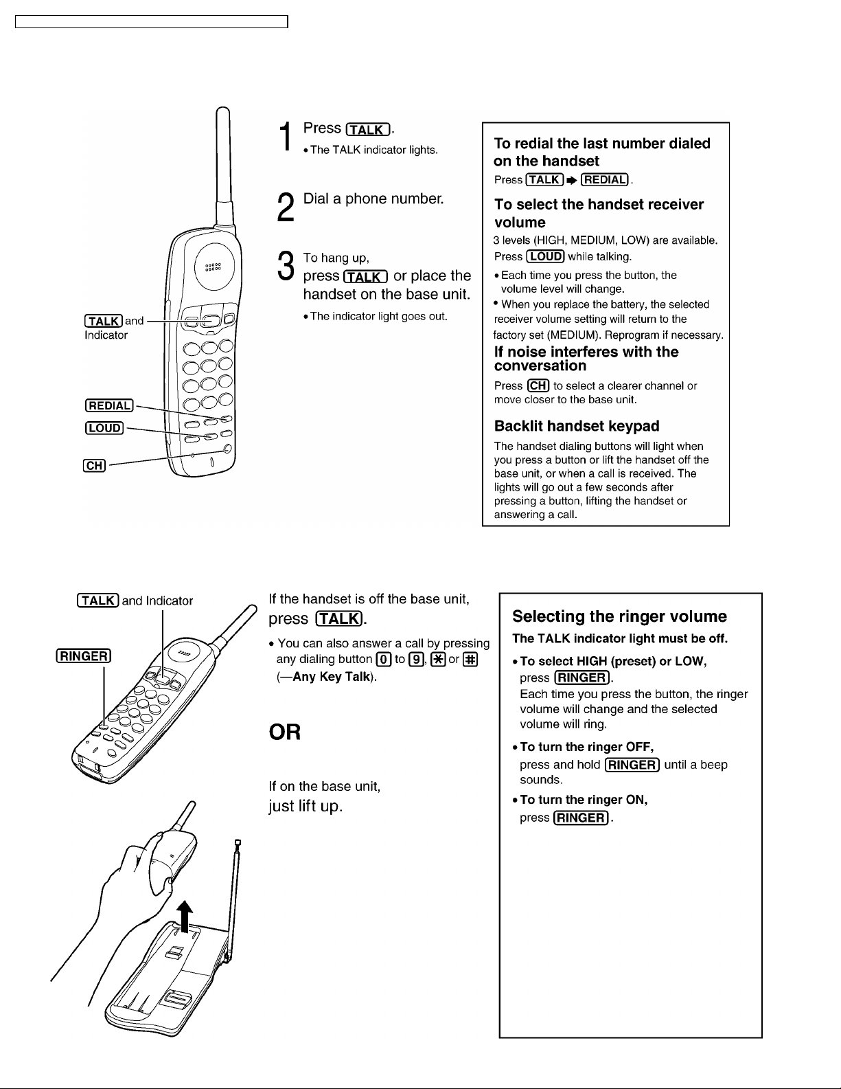
5.1. Making Calls
5.2. Answering Calls
10
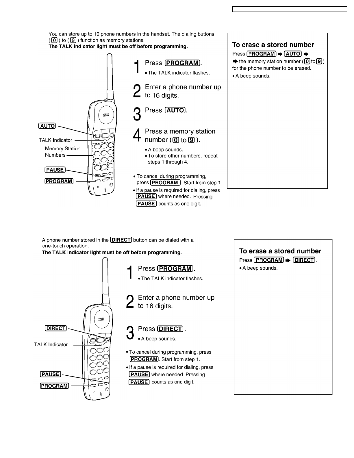
5.3. Storing Phone Numbers in Memory
KX-TC1205RUB / KX-TC1205RUW / KX-TC1205RUS / KX-TC1205RUF
5.4. Storing a Phone Number in the DIRECT Button
11
KX-TC1205RUB / KX-TC1205RUW / KX-TC1205RUS / KX-TC1205RUF
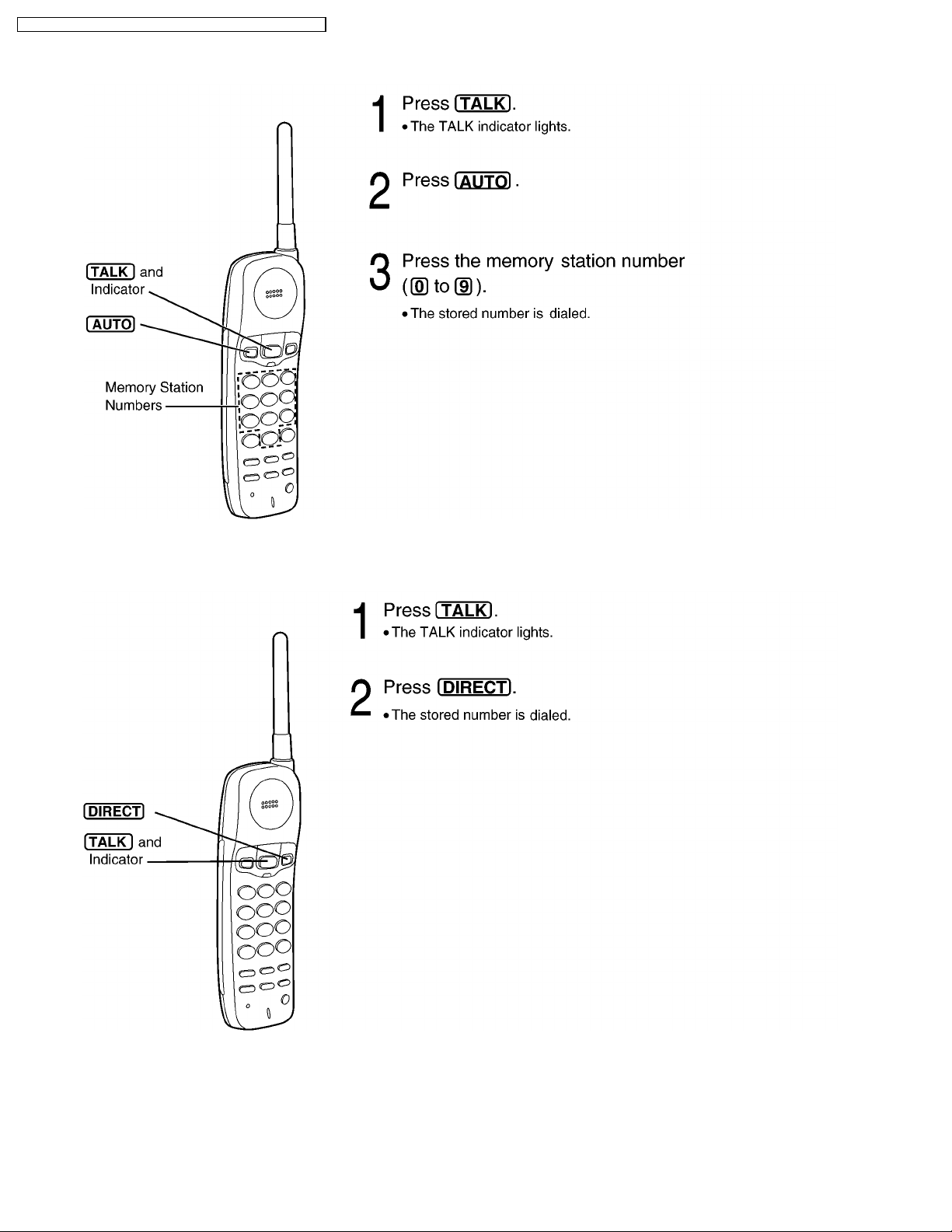
5.5. Dialing a Stored Number
5.6. Dialing a Stored Number in the DIRECT Button
12
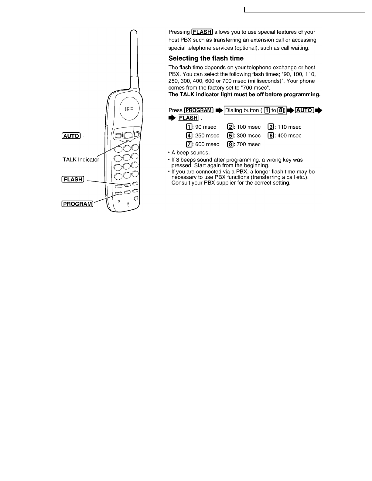
5.7. FLASH Button
KX-TC1205RUB / KX-TC1205RUW / KX-TC1205RUS / KX-TC1205RUF
13
KX-TC1205RUB / KX-TC1205RUW / KX-TC1205RUS / KX-TC1205RUF
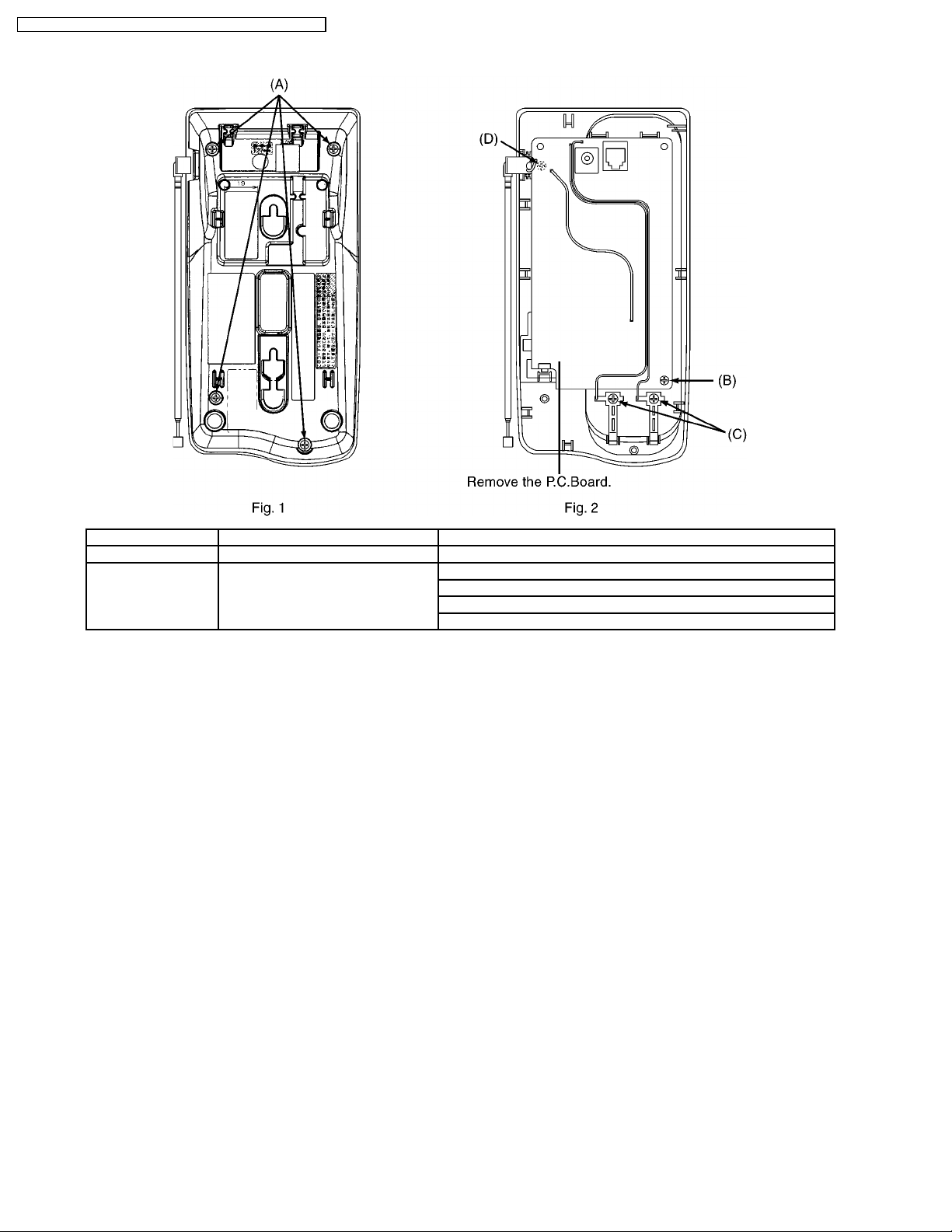
6 DISASSEMBLY INSTRUCTIONS
Show in Fig. To remove. Remove.
1 Lower Cabinet Screws (2.6 × 12)....................... (A) × 4
2 Main P.C. Board Screws (2.6 × 6)......................... (B) × 1
Screws (2.6 × 6)..........................(C) × 2
Screws (2.6 × 12)........................(D) × 1
Main P.C. Board.
14
KX-TC1205RUB / KX-TC1205RUW / KX-TC1205RUS / KX-TC1205RUF
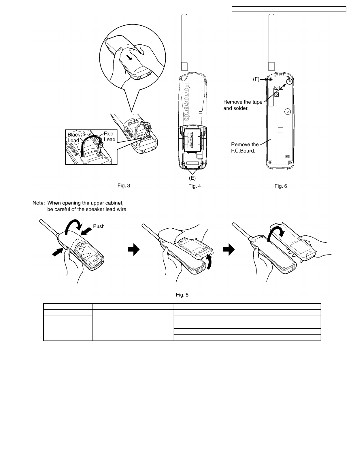
Show in Fig. To remove. Remove.
3 Rear Cabinet Battery compartment cover.
4 Screws (2.6 × 12)......................(E) × 2
5 Main P. C. Board Screw (2.6 × 12)........................(F) × 1
Tape and solder.
Main P. C. Board.
15

KX-TC1205RUB / KX-TC1205R UW / KX-TC1205RUS / KX-TC1205RUF
7 TROUBLESHOOTING GUIDE
Cross Reference:
Check Power (P.17)
Bell Reception (P.18)
Check Battery Charge (P.19)
Check Link (P.20)
Check Handset Transmission (P.22)
Check Handset Reception (P.22)
16
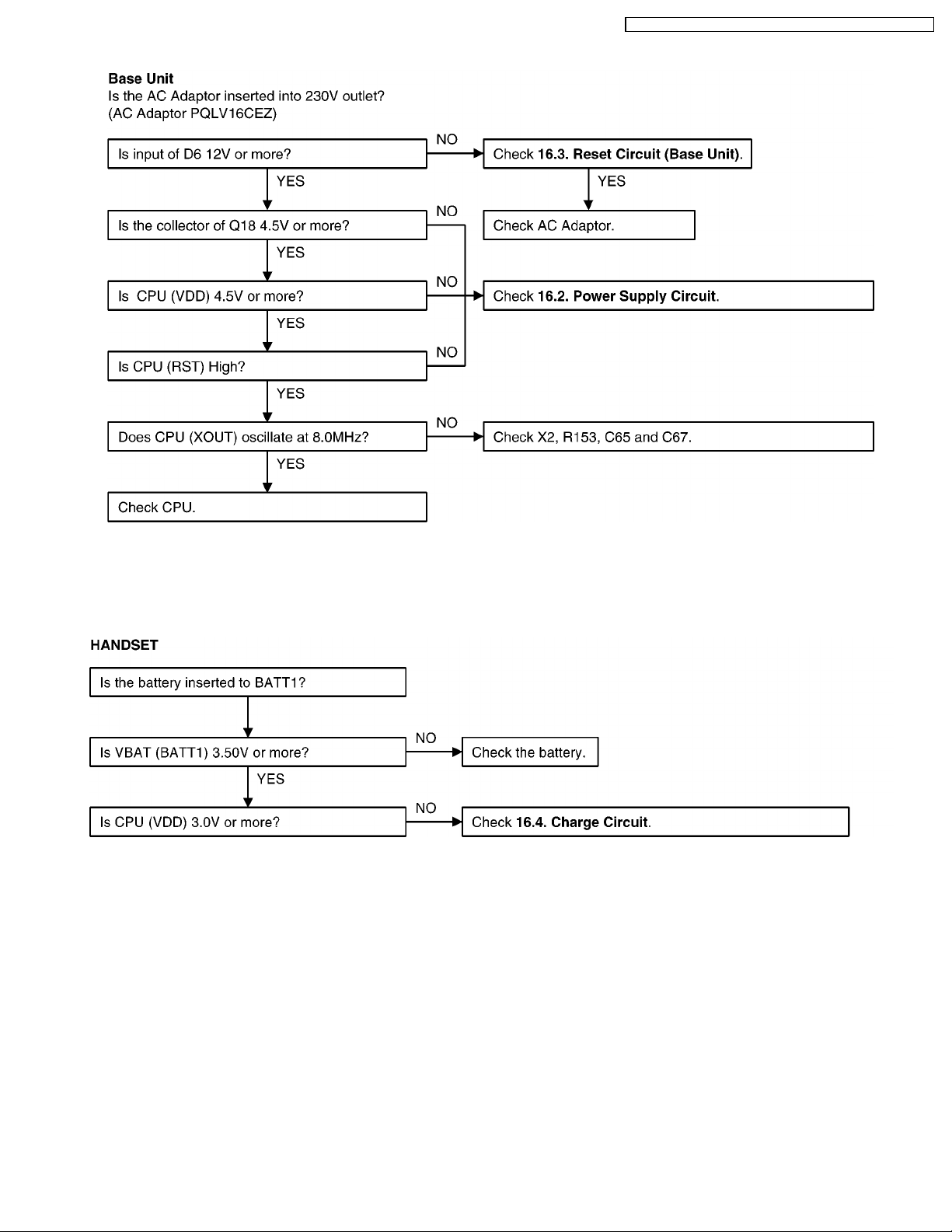
7.1. Check Power
KX-TC1205RUB / KX-TC1205RUW / KX-TC1205RUS / KX-TC1205RUF
Cross Reference:
Reset Circuit (Base Unit) (P.40)
Power Supply Circuit (P.39)
Cross Reference:
Charge Circuit (P.41)
*: Each measurement points are shown in CIRCUIT BOARD (Base Unit) (P.65) or CIRCUIT BOARD (Handset) (P.67)
Note:
CPU: IC2
Note:
CPU: IC2
17
KX-TC1205RUB / KX-TC1205RUW / KX-TC1205RUS / KX-TC1205RUF
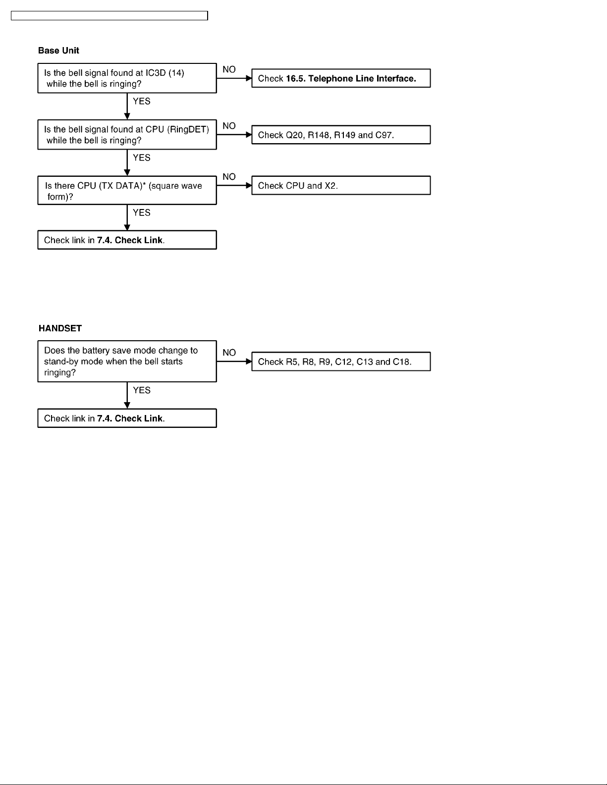
7.2. Bell Reception
Cross Reference:
Check Link (P.20)
Telephone Line Interface (P.41)
Cross Reference:
Check Link (P.20)
*: Each measurement points are shown in CIRCUIT BOARD (Base Unit) (P.65) or CIRCUIT BOARD (Handset) (P.67)
Note:
CPU: IC2
18

7.3. Check Battery Charge
KX-TC1205RUB / KX-TC1205RUW / KX-TC1205RUS / KX-TC1205RUF
Cross Reference:
Charge Circuit (P.41)
Power Supply Circuit (P.39)
Cross Reference:
Reset Circuit (Handset) (P.45)
*: Each measurement points are shown in CIRCUIT BOARD (Base Unit) (P.65) or CIRCUIT BOARD (Handset) (P.67)
Note:
CPU: IC2
Note:
CPU: IC2
19

KX-TC1205RUB / KX-TC1205RUW / KX-TC1205RUS / KX-TC1205RUF
7.4. Check Link
**: Refer to Adjustment (P.24) Note:
CPU: IC2
RF IC: IC1
*: Each measurement points are shown in CIRCUIT BOARD (Base Unit) (P.65) or CIRCUIT BOARD (Handset) (P.67)
20
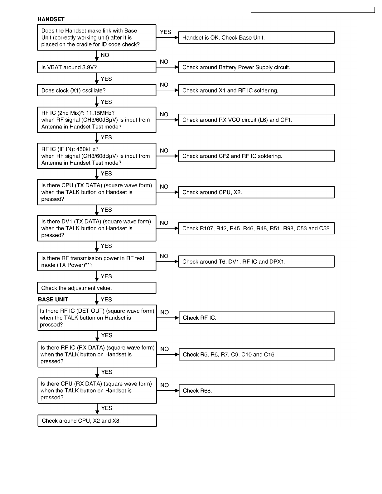
KX-TC1205RUB / KX-TC1205RUW / KX-TC1205RUS / KX-TC1205RUF
**: Refer to Adjustment (P.27). Note:
CPU: IC2
RF IC: IC1
*: Each measurement points are shown in CIRCUIT BOARD (Base Unit) (P.65) or CIRCUIT BOARD (Handset) (P.67)
21
 Loading...