

Page 1
MODEL NO.
lease read this manual before using the
Page 2

oreword
This manual describes how to use the KX-A271 software package which is used to assist in programming the
Digital Super Hybrid Systems (abbreviated to “DSHS” in this manual) KX-TD1232 and KX-TD8 16. The KXA271 enables you to confirm, change, load and save the System Data. It can also diagnose DSHS lines and
cards, and edit files in a floppy disk (FD) or a hard disk (HD) in which the System Data is stored.
For
However, the Batch files of inapplicable ROM versions can be saved in PC and they am converted to the new
version automatically. The converted vtrsion can be loaded into the DSHS of applicable ROM versions.
-7D1232,
this version is applicable to ROM version PO1 IJ and ROM versions from PO1 1N.
Page 3
ter
The System ....................................................................................................................... l- 1
System Configuration ...................................................................................................... l- 1
er
2-6
2-7
ile Configuration ...........................................................................................................
Starting the System
................................................................................................ ..-....-.
efore you begin
2-1
2-2
2-3
2-4
2-5
age Qrgankation ........................................................................................................... 2- 1
Flow Chart of the Screens ................................................................................................ 2- 3
Assigning Items.. .............................................................................................................. 2- 4
Function Keys
...........................................................................................................
Use of F2 (COPY) Kej
Help Option-
...................................................................................................................... 2-10
.................................................................................................... 2- 7
..-
Mode Structure.. .............................................................................................................. 2-l 1
perating Flow Chart
.....................................................................................................
...
l- 3
l- 3
2- 6
2-12
er
ter
2-9
Menu Tree ........................................................................................................................ 2-14
dial Screen
Initial Screen
3-1
.................................................................................................................... 3-l
rogramrning
4-1
Main Menu ....................................................................................................................... 4-l
4-2
Line ...................................................................................................................................
1. CO
2.
Line Scrling ........................................................................................................
CO Lint Groups (TRG) ............................................................................................ 4- 6
1
4- 2
4- 3
Page 4
4-3 Station . . . ..*.................................................................................................................................
4-8
Station Setting 1 . . . . . . . . . . . . . . . . . . . . . . . . . . . . . . . . . . . . . . . . . . . . . . . . . . . . . . . . . . . . . . . . . . . . . . . . . . . . . . . . . . . . . . . . . . . . . . . . . . . . . . . . . . . . . . . .
1.
2. Station
3. Station Setting 3 ................................................................................................................
4. Station Setting 4
5. Rexible Keys 1 ..................................................................................................................
6. Flexible Keys 2 ..................................................................................................................
7. DSS . . . . . . . . .._........................................................._.......................................-.......................
4-4 System . . . . . . . . . . . . . . . . . . . . . . . . . . . . . . . . . . . . . . . . . . . . . . . . . . . . . . . . . . . . . . . . . . . . . . . . . . . . . . . . . . . . . . . . ..-..............-.............................
01.
Day
02.
Class of Service .......................................................
03.
Speed Dial .........................................................................................................................
Setting 2
/Night .......................................................................................
................................................................................................................
................................................................................................................
:. ............................... 4-32
:...................._ ....................................
4-9
4-12
4-14
4-16
4-18
4-23
4-27
4-31
4-34
4-37
(
04.
Absent Messages . . . . . . . . . . . . . . . . . . . . . . . . . . . . . . . . . . . . . . . . . . . . . . . . . . . . . . . . . . . . . . . . . . . . . . . . . . . . . . . . . . . . . . . . . . . . . . . . . . . . . .._._.._..
05.
Flexible Numberiw ~~.~.~.~..~.~.~.~...................~......................~................................................
06.
Account Code / Special Carrier . . . . . . . . . . . . . . . ..__........_.........._..................................................
07.
Timer . . . . . . .._................. __ . . . . . . . . . . . . . . . . . . . . .._....~..................._..........................................._......_..
08.
09.
4-5 Toll Restriction ........................................................................................................................
Voice Mail . . .._......._............................._............... _........................._..........................__........
Miscellaneous . . . . . . . . .._._......... - . . . .._......................................~........~.............................~........~
10.
System Time . . . . . . . . . . . . .._...._........__..................................._............................................_....... 4-53
11.
Version _._..._.._.___ _ . . ..__.____.___ _ _._..___....____ _ .f...__._._._.._............._... _ . . . . . . . . . _ . . . . . . . . . . . . . . . . . . . ..__.........._
1. TRS Deny ..........................................................................................................................
2. TRS Exception ..................................................................................................................
,.
4-39
4-41
4-43
4-45
4-48
4-50
4-55
4-57
4-58
4-60
ii
Page 5
4-6 ARS (Automatic Route Selection)
. . . . . ..*...*............*..................-.
. . . . . . ..f.....................
. . . . . . . . . . . . ..f
4-62
ARS Mode / Time / Modify Data
1.
ARS Routing Plan .___...... . . . . . . . . . . . . . . . . . . . . . . . . . . . .._..........................................-..-.......
2.
3.
ARS Leading Digit . . . . . . . . . . . . . . . . . . . . . . . . . . . . . . . . . . . . . . . . . . . . . . . . . . . . . . . . . . . . . . . .
4-7 Aux. Ports . . . . . . . . ..I........................................... . . . . . . . . . . . . ..f................
1. Music & Paging
2.
Admin & SMDR & *MODEM . . . . . . . . . . . . . . . . . . . . . . . . . . . . . . . . . . . . . . . . . . . . .
*3.
DISA . . . . . . . . . . . . . . . . . . . . . . . . . . . . . . . . . . . . . . . . . . . . . . . . . . . . . . . . . . . . . . . . . . . . . . . . . . . . . . . . . . . . .._...........................................
. . . . . . . . . . . . . . . . . . . . . . . . . . . . . . . . . . . . . . . . . . . . . . . . . . . . . . . . . . . . . . . . . . . . . . . . . . . . . . . . . . . . . . . . . . . . . . . . . . . . . . . ..-.......
. . . . . . . . . . . . . . . . . . . . . . . . . . . . . . . . . . . ..-...
4-8 Additional Function . . . . . . . . . . . . . . . ..l.................... . . . . . . . . . . . . . . . . . . . . . . ..-..*...
4-9 Caller ID . . . . . . . . . . . . . . . . . . . . . . . . . . . . . . . . . . . . . . . . . . . . . . . . . ..f.... *f..*...*f.....................
. . . . . . . . . . . . . . . . . . . . . . . . . . . . . . . . . . . . . . . . . . . . .
. . . . . . . . . . . . . . . . . . . . . . . . . . . . . . . . . . . . . . . . . . . .
*..........*......................*.........
. . . . . . . . . . . . . . . . . . . . . . . . . . . . . . . . . . . . . . . . . . . .
. . . . . ..*................*............s......
..l.......*............*.....*....*.f.......
apter anagernent
5-1
isk File
Management . . . . . . . . . . . . ..~................................... . . . . . . . . . . . . . . . . f . . . . . . . . . I.. . . . . . . . . . ..l.....*....**...... 5- 1
. . . . . . . . . . . . . . . .
4-63
4-65
4-67
4-69
4-70
4-72
4-75
4-77
4-83
6-1
6-2 System Data Save
6-3 System Data Load (PC-+DSHS)
*6-4 Test
SHS Management
. . . . . . . . . . . . . . . . . . . . . . . . . . . . . . . . . . . . . . . . . . . . . . . . ...‘. . . . . . . . . . . . . ..*................ . . . ..~1..~.........f...........~f....~.......f~..........
Main
Menu . . . . . . . . . . . . . . . . ..*............ . . . . . . . . . . . . . . . . . . . . . . . . . . . . . . . . . . . . . . . . . . . . . . . . . ..f.........
(DSHS-+PC)
. . . . . . . . ..*....................................................*.......*...................-.
. . ..~....~................................*..~................................~........~.....-.-
6-I
6-2
6-3
6-4
6-4.1 Test Entry . . . . . . . . . . . . . . . . . . . . . . . . . . . . . . . . . . . . . . . ..~..._.__._.._.._........................................~..................~............~ 6-4
6-4.2
System Selection . . . .._......__ _ _......._......._.._........................_............................ _..._ . . . . . . . . . . . . . . . . . . . . . . .._..
6-4.3
Test Menu . . . . . . . . . . . . . . . . . . . . . . . . . . . . . . . . . . . . . . . . . . . .._...........................................f........................................
1. DTMF G/R Test
EXT Card Tesr ...................................................................................................................
2.
CO Card Test
3.
....................
..................................................................................................................... 6-12
............................................................................................
6- 5
6-6
6-7
6- 9
*: Available for KX-TDI 232 only.
. . .
111
Page 6

4.
DISA Test . . . . . . . . . . . .._.............._..._.............................._..........................................................
6-16
pter
8-
5.
DPH, RMT, CONF Test . . . . .._.............._..................._............................_..................._.........
Caller ID Test . . . . . . . . . . . . . . . . .._.............................................~...................................................
6.
7.
8.
Test . . . . . . . . . . . . . . . . . . . . . . . . . . . . . . . . . . . . . . . . . . . . . . . . . . . . . . . . . . . . . . . . . . . . . . . . . . . . . . . . . . . . . . . . . . . . . . . . . . . . . . . . . . . . . . . . . . . . . . . . .....
SIC
PT Test . . . . . . . . . . . . . . . . . . . . . . . . . . . . . . . . . . . . . . . . . . . . . . ..*.........................-...............................-...................
6-20
6-24
6-26
6-28
ec
. . . . . . . . . . . . . . . . . . . . . . ..*.....................*.............*............
S-232C Connect . ..l........................................................................................................
. . . . . . . . . . ..~......~.......~...~.......~......~................~........~..........~.................~~....~
Disconnect .*..........................................~.......~~.......~.............~.........*.....~...................~..~..... 7- 7
Information Display
. . . . . . . . . . . ..*.....................................................*...........*.....*..........*.......
7- 1
7- 2
7- 4
s- 1
8-2
Save Screen .f.................................................................................................................... 8- 1
.
.
*: Available for KX-TDI 232 only.
iV
Page 7
Chapter
The System
The Digital Super Hybrid System (abbreviated to “DSHS” in this manual) works under PC-DOS in IBMPC. The system and data can be stored either in FD or HD.
1-2 System Configuration
The configuration of the system is as explained below.
1.
Master Computer
The DSHS works with an IBM-PC XT/AT or compatible personal computers.
2.
OS
Version 3.1 or later versions of PC-DOS (MS-DOS) is requited.
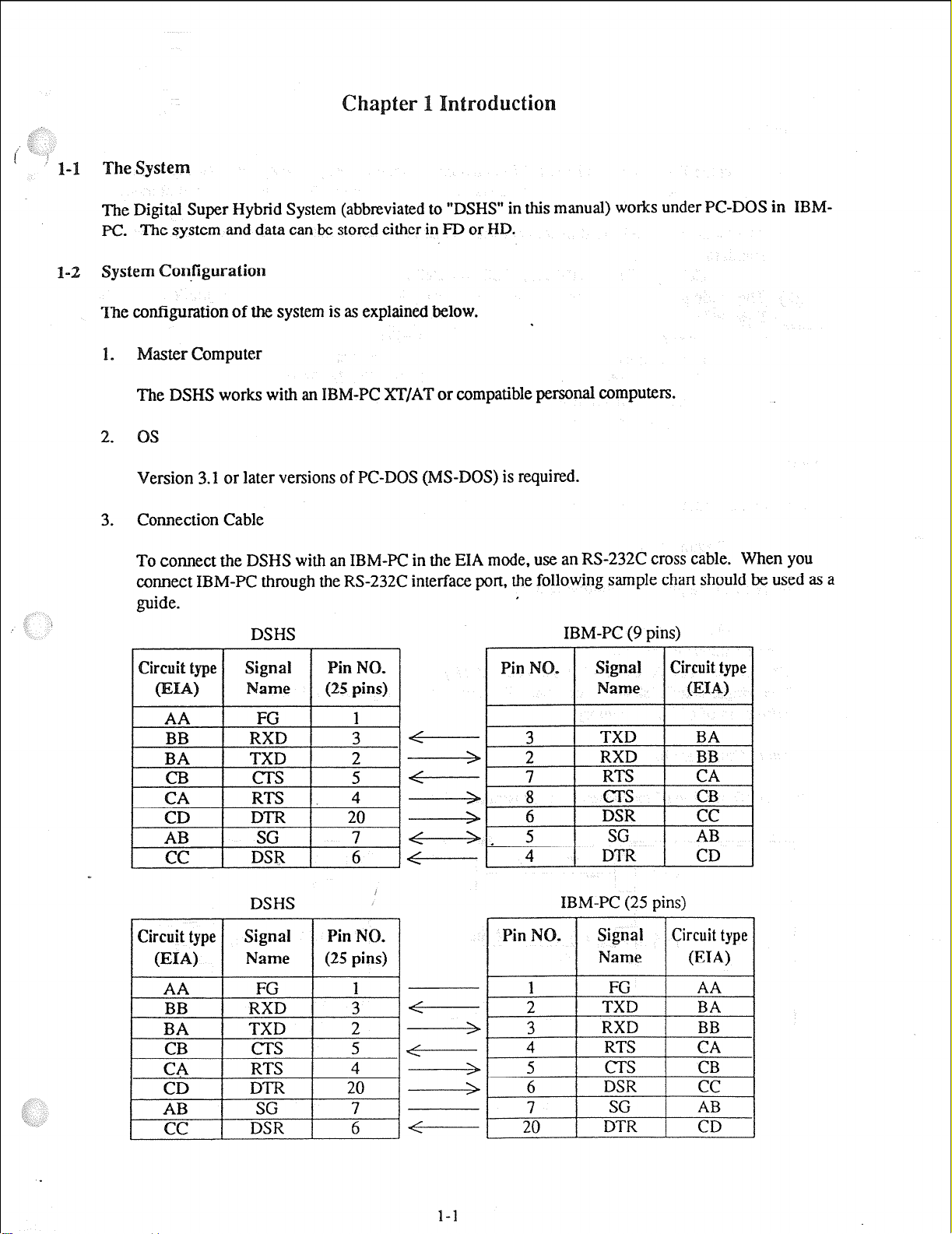
3.
Connection Cable
To connect the DSHS with an IBM-PC in the EIA mode, use an RS-232C cross cable. When you
connect IBM-PC through the RS-232C interface port, the following sample chart should be used as a
guide.
DSHS
BA TXD } 2
cl3 cl-s I 5
CA RTS 4
CD
AB SG
cc DSR 6
BB RXD 3
BA TXD 2
CB CT.5 5
CA RTS 4
CD DTR 20
AB SG 7
cc DSR 6
DTR 20
7
DSHS
IBM-PC (9 pins)
-4-----I 3
___d 2
-fs+--- 7
- 8
/I s
-g----q 4 1 DTR 1 CD
I
b 6 DSR cc
Pin NO.
%- 3 RXD BB
1 TXD
RXD BB
RTS CA
CTS CB
1
SG
I
IBM-PC (25 pins)
Signal Circuit type
Name
1
2
FG AA
TXD BA
I
I
!
I
BA
AB
@IN
I
1
1
l-l
Page 8
Modem
4.
To connect the DSHS with an IBM-PC from a remote site, use a Hayes compatible modem (AT
command). The RS-232C straight cable is necessary to connect the DSHS with an external modem.
(1) The modem which is used to connect with the DSHS must be able to use one of the following
standards :
CCITT V.21, CCJTT V.22, Bell 103, Bell 212A.
(2) The modem must be also able to use the following AT commands to assign the modem from the
IBM-PC :
Z=Reset
.
D=Dial
E=Echo back H=Lme hook
V=Result code
B=Communication standard
F=Full Duplex Mode
+++=Escape
S=Register assignment
<Note>
If the modem cannot use the commands mentioned above, it may work improperly.
5. Hardware Requirement
The IBM-PC requires the following items.
I
; The KX-A271 floppy disk
* A communication adaptor
0 CRT adaptor (CGA, EGA, MCGA, VGA, MDA)
e Two single-sided disk drives or a hard disk drive plus a single-sided disk drive
* Minimum of 640K of memory.
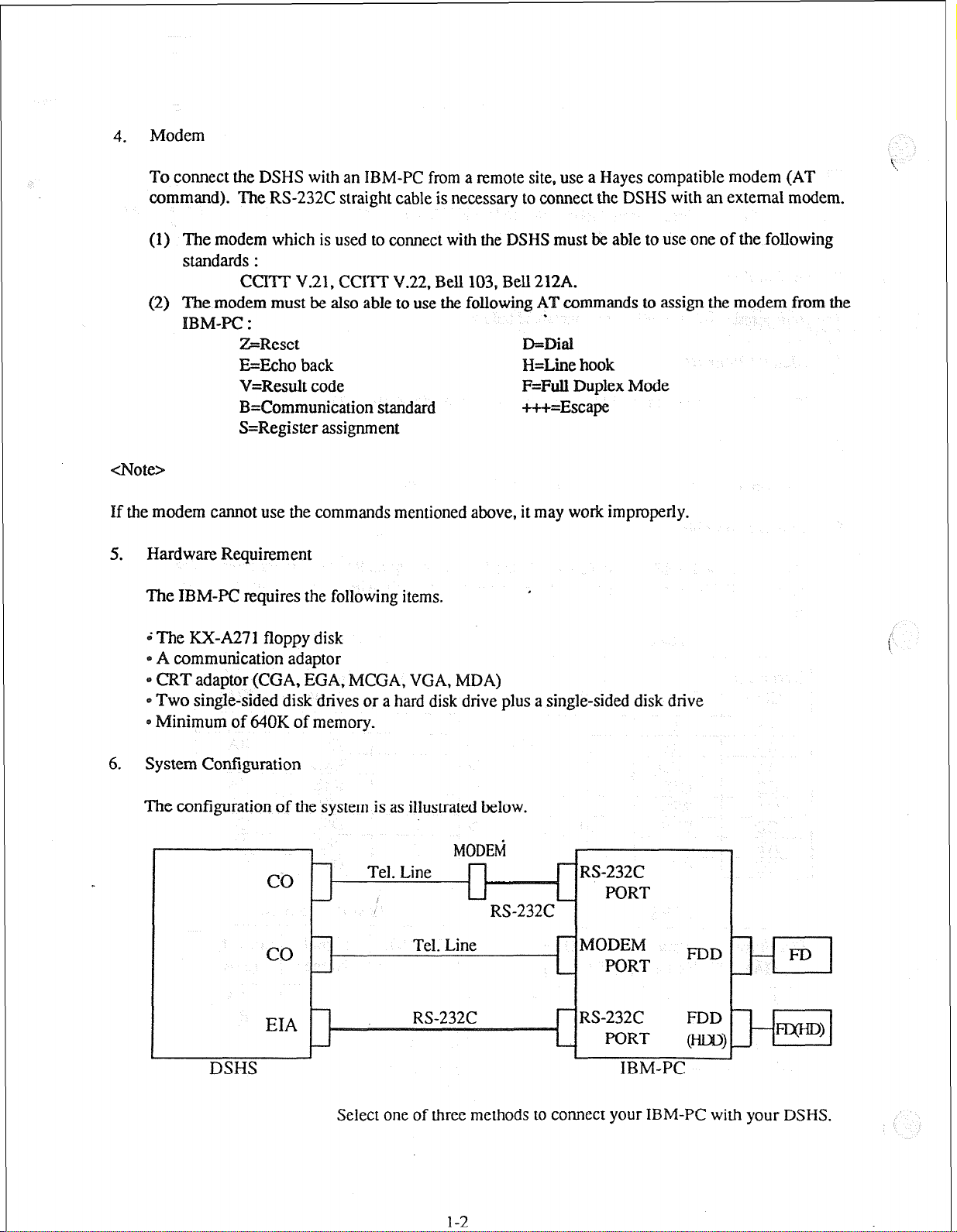
6. System Configuration
The configuration of the system is as illustrated below.
I
co
MODEti
I
RS-232C
PORT
MODEM R>D
PORT
EIA
J
DSHS
RS-232C FDD
PORT ml
L
IBM-PC
Select one of three methods to connect your IBM-PC with your DSHS.
l-2
Page 9
l-3 File Configuration
The KX-A271 software is provided on a 35 inch FD, 2DD(720K byte) format. It contains the following
tile :
E1232A.EXE --Execution file
You may make the following files if desired.
*.DBE
*.DBD --Database file of Version 1 .xx
*.DBA
tatiing Ihe System
(1) Insert the KX-A271 disk into drive A.
(2) Change the cunznt directory to drive A.
(3) Enter the command, “E1232A” after the prompt sign ‘b” and press Enter key.
(4) The initial screen appears.
--Database file of Version 2.xx (for KX-TD1232 of ROM version PO1 1J
and of ROM versions from PO1 1N)
--ASC II file
.
<Condition>
1
(1) You can exchange the original disk into the disk in which the database file is stored &er the initial
screen appears.
(2) You can copy the KX-A271 disk into a hard disk or a floppy disk.
(3) If your CRT adaptor is MDA, enter the command “E1232A /MDA”.
1-3
Page 10

.,*n--r L.
.c-
-
This chapter provides you the basic operation which is common to all System Data Program including the layout
of the screen, function keys, various messages, and the operating flow chart.
The figure below is a sample screen of CO Line Setting.
.C.O Liie~Setting -7 - - -(l)
COCT D D P C CPC
No. 0 R I T P I Detection
N G A M S D Mode
L F
01
02
03
04
05
06
07
08
09
10
11
12
[l] D 80 10 N Disable Disable
N [2] P 160 20 N 1OOms Enable Disable Disable
Y [3] D 80 10 N 2OOms Enable Disable Disable
Y [4] P 80 10 N 300ms Enable Disable Disable
Y [5] P 80 10 N 4OOms Enable Disable Disable
Y [6] P 80 10 N 5OOms Enable Disable Disable
Y [7] P 80 10 Y 6OOms Enable Disable Disable
Y [S] P 80 10 N 4OOms Enable Disable Disable
Y [8] P 80 10 N 4OOms Enable Disable Disable
Y [8] P 80 10 N 400ms Enable Disable Disable
Y [8] P 80 10 N 4OOms Enable Disable Disable
Y [8] P 80 10 N 400ms Enable Disable Disable
Off-l&e- - (2) KX-TD1232 Both
DLLl:l
EXTNo ----
Night
EXTWW EXTIloS3
---
-
-36)
- -(7)
Hit spacebar to select parameter - - - - - - - (4)
@j
Title Name:
(1)
DSHS Connecting
(2)
@J HELP /?&-PAC@N-PAC@J SAVE H EXIT -
The title of the program is displayed here.
Status: The condition of connecting with the DSHS is displayed here.
(3) Batch File Type: One of the following Batch file types is displayed.
0 Empty: No Batch files are saved in the system.
* KX-TD1232 Both: The Batch files of the KX-TD1232 Master &
Slave are saved in the system.
- KX-TD1232 Master: The Batch file of the KX-TD1232 Master is
saved in the system.
2-1
- - (5)
Page 11

0 KX-TD1232 Slave:
0 KX-TD8 16: The Batch file of the KX-TD8 16 is saved in the
The Batch file of the KX-TD1232 Slave is
saved in the system.
system.
Message:
(4)
The order priority of the message is as following:
Error Message Status Message
(5) Function Keys:
(6) Items:
(7) Fields: Parameters are entered into them.
Error Message, Status Message, and Operation Guide Message are
displayed here.
*Error Message: Appears when an ermr occurs.
&~tus Message: Appears when it is necessary to show the proceeding
job.
*Operation Guide Message: Shows the way of operation.
Operation Guide Message.
Appear when it is possible to operate them.
(For further information see “2-4 Function Keys”)
The names of items to be assigned.
2-2
Page 12

2-2
ow Chart of
Initial
I
ENTER
the
Screens
I
Main Menu
EXIT
ENTER EXIT
Edit
Page- 1
1
e-----=
I
ENTER
Edit
&lain Menu
I
EXIT
N-PAGE
I
P-PAGE
1‘
Page-n
‘-PAGI
2-3
N-PAGE
P-PAGE
P-PAGE
l.T
Page 13
2-3 Assigning Items
This section provides you the basic operation of programming the assigning items.
1. Change the screens
@ The initial screen
Press ENTER key to advance to the next screen.
The menu screens
Press ENTER key to advance to the next screen.
Press EXIT key to return to the initial screen.
The editing screens
Press F5 (P-PAGE) key to return to the previous page.
Press F6 (N-PAGE) key to advance to the next page.
Press EXIT key to return to the menu screen.
For further information about function keys, see “2-4 Function
2.
Types of fields
I
There are two types of the fields. You can distinguish the type by a display of the cursor or a
message.
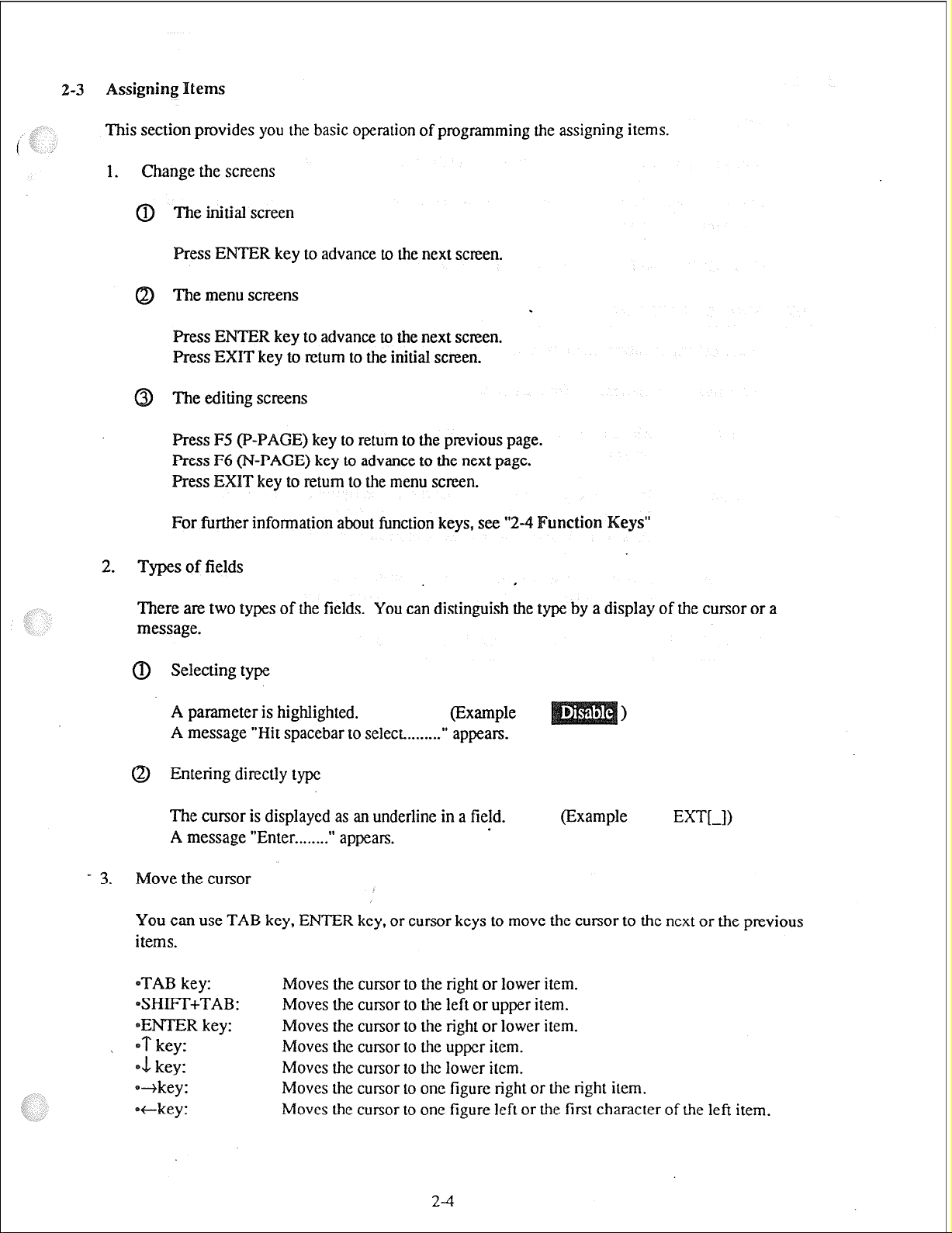
0 Selecting type
A parameter is highlighted.
(Example
A message “Hit spacebar to select........” appears.
@ Entering directly type
The cursor is displayed as an underline in a field.
A message “Enter . . . . . ...”
3.
Move the cursor
appears.
(Example
E=I-I)
You can use TAB key, ENTER key, or cursor keys to move the cursor to the next or the previous
i terns.
eTAB key:
SHIFT+TAB:
eENTER key:
j *T key:
01 key:
-key:
eckey:
Moves the cursor to the right or lower item.
Moves the cursor to the left or upper item.
Moves the cursor to the right or lower item.
Moves the cursor to the upper item.
Moves the cursor to the lower item.
Moves the cursor to one figure right or the right item.
Moves the cursor to one figure left or the first character of the left item.
2-4
Page 14
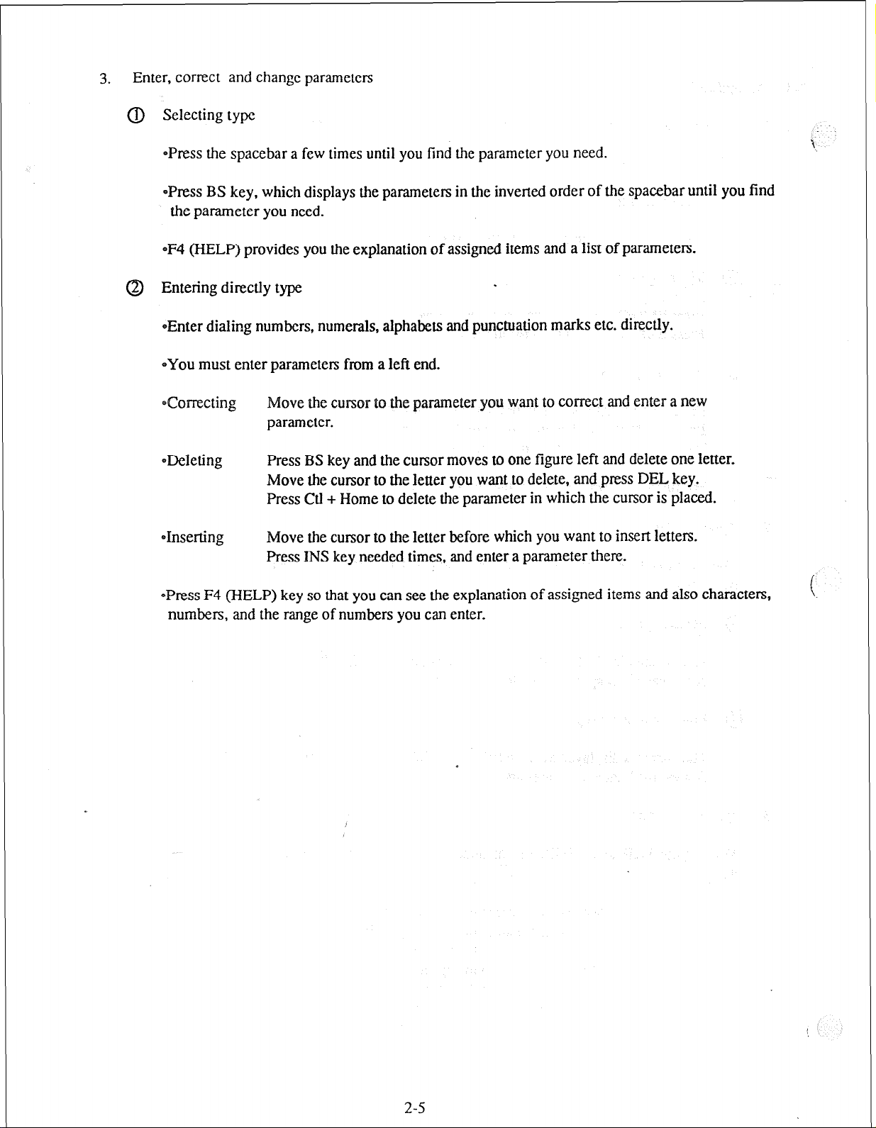
Enter, correct and change parameters
3.
(IJ Selecting type
*Press the spacebar a few times until you find the parameter you need.
~Press BS key, which displays the parameters in the inverted order of the spacebar until you find
the parameter you need.
eF4 (HELP) provides you the explanation of assigned items and a list of parameters.
Entering directly type
*Enter dialing numbers, numerals, alphabets and punctuation marks etc. directly.
~YOU must enter parameters from a left end.
Correcting
ODeleting
*Inserting Move the cursor to the letter before which you want to insert letters.
-Press F4 (HELP) key so that you can see the explanation of assigned items and also characters,
numbers, and the range of numbers you can enter.
ove the cursor to the parameter you want to correct and enter a new
parameter.
Press BS key and the cursor moves to one figure left and delete one letter.
Move the cursor to the letter you want to delete, and press DEL key.
Press Ctl + Home to delete the parameter in which the cursor is placed.
Press INS key needed times, and enter a parameter there.
.
2-5
Page 15

unction Keys
@JJcopy @
f# HELP ~P-PAG@$JN-~AGE@ SAVE @ EXIT
I
F2 (COPY) : Copies parameters by CO lines, extensions, CO line groups or jack numbers.
(For further information see “2-5 Use of F2 (COPY)
.
F4 (HELP) : Explains assigned items.
FS (P-PAGE) : Returns to the previous page.
(N-PAGE) : Advances to the next page.
F7 (SAVE) : Saves the data displayed on the screen.
FI (CONNECT) :Connects your IBM- PC with the DSHS.
F8 (EXIT) :
Returns to the Menu screen.
<Condition>
(1) When you press F5 (P-PAGE), F6 (N-PAGE) or F8 (EXIT) without pressing F7 (SAVE) to save the
changed data, a message “Screen will be changed without saving new data. OK?(Y/N) a” appears.
Press “Y” or “y” to carry out or press “N” or “n” to cancel.
(2) If your IBM-PC is disconnected from the DSHS while saving the data, you should save it again after
reconnecting the PC.
2-6
Page 16
2-5 Use
of F2
(COPY) Key
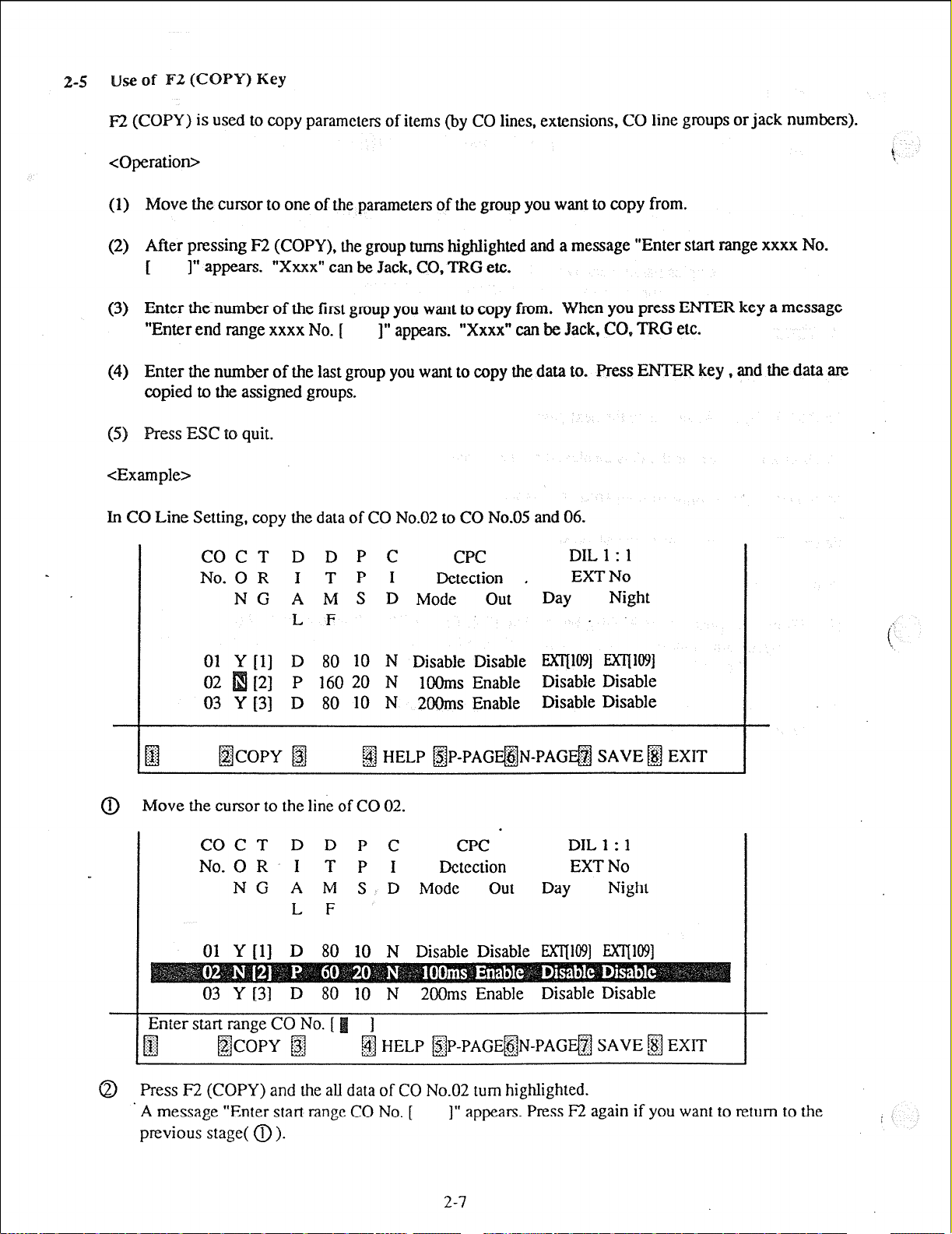
F2 (COPY) is used to copy parameters of items (by CO lines, extensions, CO line groups or jack numbers).
<Operation>
(1) Move the cursor to one of the parameters of the group you want to copy from.
(2) After pressing F2 (COPY), the group turns highlighted and a message “Enter start range xxxx No.
I” appears. “Xxxx” can be Jack, CO, TRG etc.
[
(3) Enter the number of the first group you want to copy from. When you press ENTER key a message
“Enter end range xxxx No. [ 1” appears. “Xxxx” can be Jack,
CO, TRG
etc.
(4) Enter the number of the last group you want to copy the data to. Press ENTER key,
copied to the assigned groups.
(3
ess ESC to quit.
<Example>
In CO Line Setting, copy the data of CO No.02 to CO No.05 and 06.
COCT D D P C CPC
No. 0 R I TPI Detection ,
N G A M S D Mode out
DIL 1 : 1
EXT No
Day
Night
L F
01 Y [l] D 80 10 N Disable Disable ml091 E>nll@]
02 [2]
P 160 20 N 1OUms Enable Disable Disable
03 Y [3] D 80 10 N 2OOms Enable Disable Disable
@copy B
fjJ HELP /$JP-PAGF&&PAG@ SAVE @J EXIT
@ Move the cursor to the line of CO 02.
and the
-
data are
COCT D D P C
I T P I
N G A M S D Mode
CPC -
Detection
out
DIL 1 : 1
EXT No
JW
Night
L F
01 Y [l] D 80 10 N Disable Disable EXl7loSl EXTllO91
0 Press I32 (COPY) and the all data of CO No.02 turn highlighted.
A message “Enter start range CO No. [ 1” appears. Press F2 again if you want to return to the
previous stage( 0 ).
2-7
Page 17

COCT D D P C
I T P I
N G A M S D Mode
L F
CPC
Detection
out
DIL 1 : 1
EXT No
Day
Night
P 80 10 N 3
05 Y [5] P 80 10 N
4OUms Enable Disable Disable
ble Disable Disable
06 Y [6] P 80 10 N SOOms Enable Disable Disable
~P-PAG~ N-PAG@j
sAw3 m Exrr
@ Enter CO No.05 press F2 again if you want to return to the previous stage ( 0).
COCT D D P C
I T P I
N G A M S D Mode out
Day
Night
L F
05 Y [5] P 80 10 N 400ms Enable Disable Disable
06 Y-[6] P 80 10 N SOOms Enable Disable Disable
-
-
@ press ENTER key and a message “Enter end range CO No.[
press F2 again if you want to rctum to the previousstage (0).
COCT D D P C CPC DIL 1 : 1
I T P I Detection EXT No
N G A M S D Mode out
L F
01 Y [l] D 80 10 N Disable Disable WI@] EXT@l9]
04 Y [4] P 80 10 N 300ms Enable Disable Disable
05 Y [S] P 80 10 N 400ms Enable Disable Disable
Enable Disable Disable
2-8
Day
Night
-
Page 18

0 Enter CO No.06
COCT D D P C
No. 0 R
I T P I
CPC
Detection
N G A M S D Mode out
L F
01 Y [l] D 80 10 N Disable Disable EXIJ109] MT[ltB]
02 N [2] P 160 20 N 1OOms Enable Disable Disable
03 Y [3] D 80 10 N 2OOms Enable. Disable Disable
04 Y [4] P 80 10 N 3OOms Enable Disable Disable
05 N [2] P 160 20 N 1OOms Enable Disable Disable
06 N [2] P 160 20 N
-
gJ
f$@opy f#
f#
1OOms
Enable Disable Disable
HP-PAGE@JN-PAGF# SAVE @j E
ss ENTER key and the data of CO No.05 and No.06 turn to the same as C
The data are saved and the screen returns to the previous stage( 0).
<Note>
(1) Press ESC key at any stage to quit the copy mode.
’
DIL 1 : 1
EXT No
Day
Night
-
(2) When you copy the data of Flexible Keys or DSS, the data of the whole screen are copied to another.
You cannot copy a part of them.
.
f
2-9
Page 19
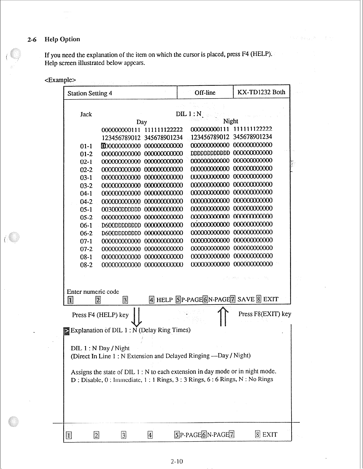
2-6
If you need the explanation of the item on which the cursor is placed, press F4 (HELP).
Help screen illustrated below appears.
4e>
Station Setting 4
01-l
01-2
02-l
02-2
03-l
03-2
04-l
04-2
05-l
05-2
06-l
06-2
07-l
07-2
08-l
08-2
003000DDDDDD
D6OODDDDDDDD
D6OODDDDDDDD
I
DILl:N.
Day
111 111111122222
012 345678901234
Off-line
KX-TD1232 Both
I
Night
111 111111122222
012 345678901234
Enter numeric code
pj
Press F4 (HELP) key
Explanation of DIL 1 : lay Ring Times)
DIL 1 : N Day /Night
(Direct In Line 1 : N Extension and Delayed Ringing -Day /Night)
Assigns the state of DIL 1 : N to each extension in day mode or in night mode.
D : Disable, 0 : Immediate, 1 : 1 Rings, 3 : 3 Rings, 6 : 6 Rings, N : No Rings
fg fg
@J HELP ~P-PAG@N-~~~G@J SAVE@ EXIT
Press F8(EXIT) key
m EXIT
Page 20

2-7 Mode Structure
There are two types of editing modes.
Batch Editing Mode
1.
This is the way to program the DSHS by editing the PC database( To use this mode, you must
first load Disk File DB or save DSHS DB into PC DB.
Edit
1 Screen buffer
Read
Write
SAV
f
PC DB
1
\
\ SAW
&-Connect (RS-232C or MODEM) /Disconnect
\. \
2. Interactive Editing Mode
This is the way to program the DSHS directly from the PC terminal connected by the RS-232C or the
MODEM.
1 Screen buffer
Edit -
PC Terminal
i
>
Read
Write
,Conneet (RS-232C or MODEM) /Disconnect
Single system or System Connection
<Note>
When the single system is operating, parameters of some items cannot be assigned to the system
which is not operating. They are not displayed in the screens.
.
2-11
Page 21

Operating Flow Chart
2-8
i ,:
[ I
Batch Editing Mode
Save the system data
(See “Chapter 7 DSHS
Set FD or ND
Load the system data
._
., 2.
I_
:
-~
I
Connecting with
DSHS
1
Loading the data of
PC DB into DSHS
DB
Disconnecting from
.
I
I
DSHS
I
Edltmg the data In
(See Chapter 4 System
c]::tyl;::;:::)
I I
Saving the file
I
0
,
Connect PC with DSHS
(See “Chapter 7 DSHS
Connect / Disconnect)
I -~
* Load the system data
of PC DB into DSHS DB Saving the data of
(See “Chapter 6 DSHS PC DB into the file HD (See “Chapter 5
J Management”)
‘I Disconnect PC from DSHS
(See “Chapter 7 DSHS
Connect I Disconnect”)
*
1
I
Setting the file
I
1
Set FD otHD
I
. Save the system data
of PC DB into FD or
- Disk FiIe Management”)
2-12
Page 22
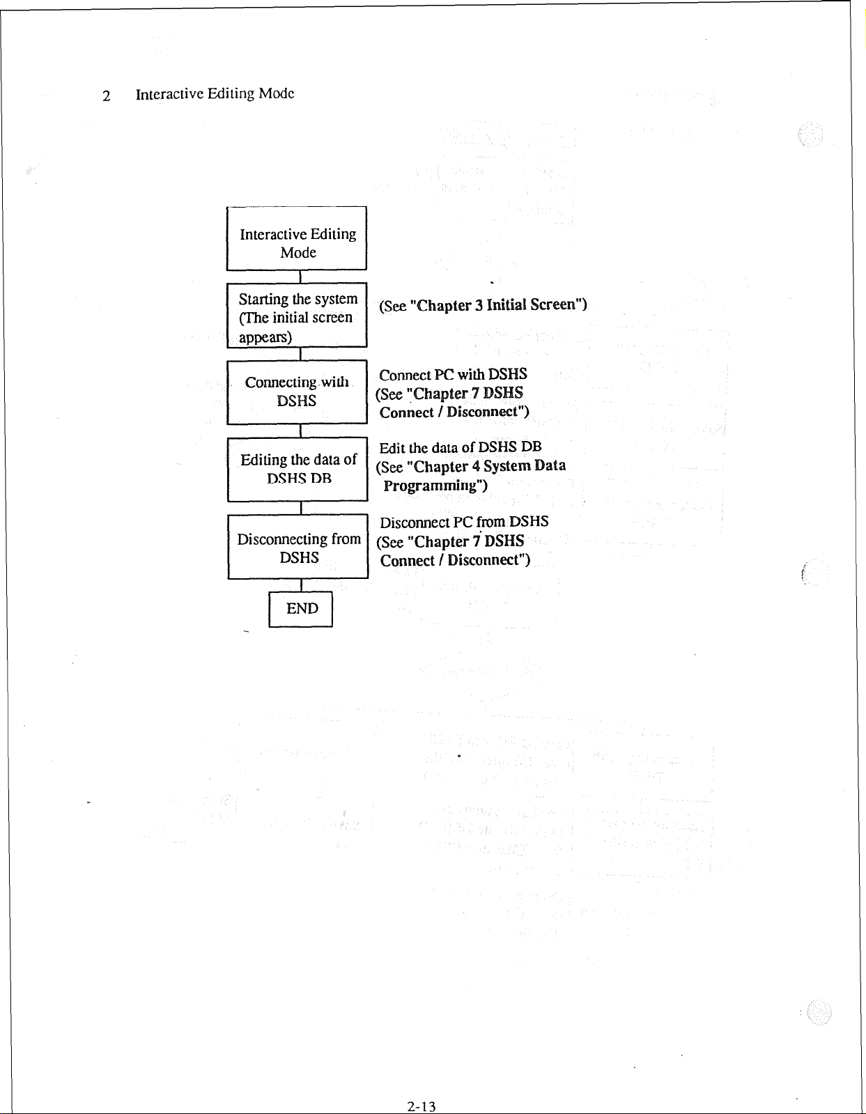
Interactive Editing Mock
2
I I
/ Interaz%iiting 1
I 1
Starting the system
(The initial screen
I
1
.
I
Edit the data of DSHS DB
“Chapter 4
Disconnect PC from DSHS
(SW "Chapter YDSHS
System
2-13
Page 23

2-9
enu Tree
Main Menu
m
Menu
{Line}
-/ Station
Edit
----r--v-.
.
stem
rSy Day/Night
1 ARS
1 DSS
Class of Service
---*A-----Soeed Dial
-------
I
ARS Mode/Time/Modify Data
-mm---ARS Routin@an
---- -----
-------
ARS Leading Digit
[ Aux. Ports
I
Music & PagQ
v--e -----
Administration & SMDR & *MODEM
-------_____
*DISA
I
-f Disk File Management 1
4DSHS Management1
mote>
*: Available for KX-TD1232 only.
I
*Test
2-14
{Addnional Function
{Caller ID
System Data Save
f System Data Load
f
*DTMF G/R Test
---w-w--*EXT Card Test
------____
*DISA Card Test
e-e--_____
{ RS232C Connect
*MODEM Connect
[ Dtsconnect
1
Page 24

Intial Screen
The screen below is displayed when you start the DSHS program.
Main Menu
Panasonic
Digital Super Nybrid System
Operating & Maintenance Tool Ver 2.xX
(C) COPYRIGHT 1993 KYUSHU MATSUSHITA ELECTRIC CO., LTD.
1. System Data Programming (Batch)
2. System Data Programming (Interactive)
3. Disk Pile Management
4. DSHS Management
5. DSHS Connect / Disconnect
6. Quit
Select the number :[J
Off-line
KX-TD1232 Both
Enter the number, and hit ENTER key
@j
- <Explanation>
[l] System Data Programming (Batch)
Edits System Data in Batch Editing Mode.
[2] System Data Programming (Interactive)
Edits System Data in Interactive Editing Mode.
[3] Disk Pile Management
Loads the data from the disk and saves them into the disk in Batch Editing Mode.
[4] DSHS Management
Saves the data from DSHS and loads them into DSHS in Batch Editing Mode and also diagnoses
DSHS in Interactive Editing Mode.
@j
m HELP &j @j
3-1
fj
.
p.j
Page 25

[S ] DSHS Connect / Disconnect
Connects the PC terminal with the DSHS by RS-232C or MODEM and disconnects from the DSHS.
[6] Quit
Returns to MS-DOS System.
<Operation>
Enter the number of the program, and press ENTER key.
(1)
When you select “1. System Data Programming (Batch)“, you must choose “3. Disk File Manage-
(2)
ment” or “4. DSHS Management” first to load or save the system data into PC DB .
(3) When you select “2. System Data Programming (Interactive)” or “4. DSHS Management”, you must
choose “5. DSHS Connect / Disconnect” first to connect the PC terminal with the DSHS.
(4) Select “6. Quit” to return :o
<Condition>
When you select “2. System Data Programming (Interactive)” or “4. DSHS Management” without
connecting the PC terminal with the DSHS, a message “Please connect with the DSHS by
5. DSHS Connect / Disconnect”.
3-2
Page 26

ain enu
The screen below appears first when you select “1. System Data Programming (Batch)“.
System Data Programming Main Menu
1. Line
2. Station
3. System
4. Toll Restriction
5. ARS
6. Aux. Ports ’
7. Additional Function
8. Caller ID
Select the number : [J
Off-line
.
KX-TD1232 Both
Enter the number, and hit ENTER key
<Operation>
(1)
Enter the number of the program, and press ENTER key.
(2) Press F8 (EXIT) to return to the initial screen.
4-1
Page 27

4-2 Line
The screen illustrated below appears when you select “1. Line”.
Line Menu
Off-line
1. CO Line Setting
2. CO Line Groups (TRG)
Select the number : [-I
KX-TD1232 Both
Enter the number, and hit ENTER key
fjYj @
<Operation>
(1)
Enter the number of the program, and press ENTER key.
(2) Press F8 (EXIT) to return to Main Menu screen.
gj fi HELP m
@
.
B
II3
EXIT
4-2
Page 28
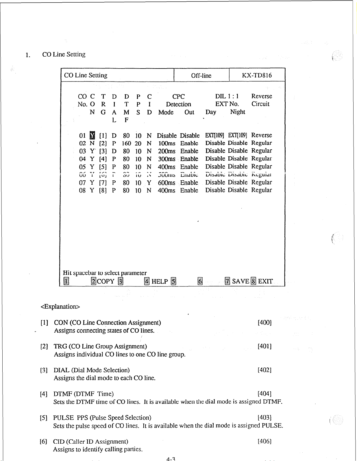
CO Line Setting
1.
i
CO Line Setting
COC T D D P C
No. 0 R I T P I Detection
N G A M S D Mode out
L F
01 [ll D 80 10 N
02 N [2] P 160 20 N
03 Y’ [3] D 80 10 N
04 Y [4] P 80 10 N
05 Y [5] P 80 10 N
c., -7 r,3 - n-. -r -.
;;7” ; ~~; ~ ;;;; ;;; ~
Disable Disable
1OOms Enable
2OOms Enable
3OOms Enable
4OOms Enable
-em
3UUlIl~ EIIcliJiL
6OOms Enable
08 Y [SJ P 80 10 N
400ms Enable
CPC
Off-line
KX-TD816
DIL 1 : 1 Reverse
EXT No. Circuit
Day
Night
EXlJ109] EX’ljW] Reverse
Disable Disable Regular
Disable Disable Regular
Disable Disable Regular
Disable Disable Regular
iXh&ii iL&ic ikguidr
Disable Disable Regular
Disable Disable Regular
IIit spacebar to select parameter
<Explanation>
[l] CON (CO Line Connection Assignment)
]4001
Assigns connecting states of CO lines.
[2] TRG (CO Line Group Assignment)
I4011
Assigns individual CO lines to one CO line group.
[3] DIAL (Dial Mode Selection)
[4w
Assigns the dial mode to each CO line.
[4] DTMF (DTMF Time)
[4041
Sets the DTMF time of CO lines. It is available when the dial mode is assigned DTMF.
[S] PULSE PPS (Pulse Speed Selection)
14031
Sets the pulse speed of CO lines. It is available when the dial mode is assigned PULSE.
[6] CID (Caller ID Assignment)
[406]
Assigns to identify calling panics.
4-3
Page 29

[7] CPC Detection Mode (CPC Signal Dctcction Incoming Set)
Sets the CPC signal dctcction time when cithcr calling or called party goes on hook.
[4051
[S] CPC Detection Out (CPC Signal Dctcction Outgoing Set)
r4151
Assigns to enable or disable to dclcct the CPC signal while calling .
[9] DIL 1 : 1 EXT No. Day /Night
(Direct In Line Extension -Day /Night) [407,408 ]
Assigns an extension for a DIL 1: 1 destination during day time or night time.
[lo] Reverse Circuit (Reverse Circuit Assignment)
.
14161
Enables or disables to detect Reverse Circuit.
a This feature is available for KX-TD816 only.
<operation>
(1) For KX-TD1232, this program consists of two pages. One displays CO No.01 through 12aand the
other displays CO No. 13 through 24.
For KX-TD816, this program consists of one page. It displays CO No.01 through 08.
(2) Move the cursor to the field in which you want to set a parameter.
(3) After editing the data, press F7 (SAVE) to save them on the screen into DB file.
(4) Use F2 (COPY) if you want to copy the data of one CO No. in another.
(5) Press F8 (EXIT) to return to Line Menu screen.
<Condition>
(1) It is possible to assign Floating Extension Number as an extension number in DIL 1 : 1.
(2) When the single system is operating, the data of DIL 1 : 1 of the system which is not operating
cannot be assigned and they are not displayed in the screen.
(3) When you copy the data of DIL 1: 1, it is invalid to copy in or from the data which are not displayed.
<Note> ,
The numbers beside the items arc program addresses which are used when you program the system by
proprietary telephones.
4-4
Page 30

TABLE of ITEMS
Assigning
Items
CON
Type of Field Sclcction of paramctcr
Selecting
Y :
COMCCL
TRG Direct 1 through 8
D : DTMF, P : Pulse. C : Call Block
Y : Identify or N: Not identify ’
or N : Disconnect
Default
Y
coOl=l, cm2=2
co03=3. coo4=4
1 digit
.
coos=s, coobd
COOM. COO8=8
----COO9=8through
CO24=8 (KX-TD1232
CPC
Detection
diode
CPC
Detection
3ut
DlLl
: 1
Xl- No.
Day
/Night
Xeverse
Zircuit
Selecting
Selecting
Selecting
and
Direct
Selecting
Disable, lOOms, 2OOms. 3OOms, 4OOms. 5OOms, 6OOms
Disable or Enable
Disable or EXT [ ]
(After selecting EXT [ 1)
0 through 9
.
2.3 or 4 digits
Reverse (detection) or Regular (no detection)
400ms
Disable
Disable
Regular
4-5
Page 31

CO Line Groups (TRG)
CO Line Groups (TRG) Off-line
T
R EXT No. Time Time Time
G Day Night (msec) (set) (set)
4 Disable Disable
Intercept
1 il@N wcrjl@l
2 Disable Disable
3 Disable Disable
5 Disable Disable
6 Disable Disable
7 Disable Disable
8 Disable Disable
Flash Pause DSC
NO 1.5 1.5 . [Ol] [08] [lo] [223
80 1.5 1.5
96 1.5
112 1.5
200 1.5 1.5
300 1.5
400 1.5
1200 1.5
[0111081[ I[ 1
1.5 WI lo81 [121[ 1
1.5 WI I 11121 WI
WI 1321 [ 1 t 1
1.5 1021 t221 1321[ I
1.5 I II I[ II 1
KX-TD 1232 Both
PBX Access
I 2 3 4
21 I 1 /=I 1221
Hit spacebar to select parameter
<Explanation>
[l] Intercept EXT No. Day / Night (Intercept Exlcnsion - Day /Night) [409,410]
Assigns extensions for destinations of intercept routing during day time or night time.
[2] Flash Time (Flash Time)
Sets the length of the Flash Time.
[3] Pause Time (Pause Time)
Sets the length of the Pause Time.
[4] DSC Time ( Disconnect Time)
Sets the length of the disconnecting time.
[S] PBX Access (Host PBX Access Codes)
Assigns the Host PBX access codes.
[4131
t4121
[4141
14111
4-6
Page 32

<Operation>
(1) Move the cursor to the ficld in which you want to set a paramctcr.
(2) After editing the data, press F7 (SAVE) to save them on the screen into DB file.
(3) Use F2 (COPY) if you want to copy the data of one CO line group in another.
(4) Press F8 (EXIT) to return to Line Menu screen.
<Condition>
(1) It is possible to.assign Floating Extension Number of Pager and DISA as an Intercept Extension
number.
(2) In case of the redundant storage of PBX AC&S No., 1 digit entry is valid.
EXAMPLE ; 8 is more valid than 81.
<Note>
The numbers beside the items arc program addrcsscs which are used when you program the system by
proprietary telephones.
TABLE of ITEMS
Assigning
Items
hnercept
EXT No.
Day /Night
Type of Field Sclcction of parameter
Selecting
and
Direct
Disable or EXT [ J
(After selecting EXT [ 1)
0 through 9 2.3 or 4 digits
.
Default
Disable
a
,
Flash Time Selecting N0,80,96,112,20,300,40,500,600,700,,1
1 loo, 1200
Pause Time Selecting 1.5, 2.5,3.5,4.5 1.5
DSC Time Selecting 1.5 or 4.0 1.5
PBX Access
No.
*(a wild card character) is used as any number.
For example:
0 * applies to numbers which begin with 0.
9 *applies to numbers which begin with 9.
Direct
0 through 9
*(a wild card character)
Maximum 2 digits
4-7
Not Stored
Page 33

4-3
Station
( .’
The screen illustrated below appears when you sclcct “2. Station.”
Station Menu
1. Station Setting 1
2. Station Setting 2
3. Station Setting 3
4. Station Settnig 4
5. Flexible Keys 1
6. Rcxiblc Keys 2
7. DSS
Off-line KX-TD1232 Both
i
Scicct the number : [-I
Enter the number, and hit ENTER key
<Operation>
(1) Enter the number of the program, and press ENTER key.
(2) Press F8 (EXIT) to return to Main Menu screen.
<Condition>
When you assign “Station Setting 2”. “Flcxiblc Keys 1”. ” FlcxiblcKcys 2”, or “DSS” in Interactive Editing
mode, the data are not loaded into DB of the DSHS by pressing only F7 (SAVE) key. They are only
saved in DB of the IBM-PC If you want to load the data into DB of the DSHS, you must press F7
(SAVE) and then F8 (EXIT) key.
Page 34

Station Setting I
1.
Station Setting 1
Jack
01-l [LO11
01-2
02-I [IO21
02-2 [202]
03-I 11031
03-2 (203J
04-l [lo41
04-2 [2041
05-l [lo51
05-2 [205]
06-l [IO61
06-2
07-I [IO71
07-2 12071
08-l II081
08-2 [208]
EXT
12011
PO61
Name
X E
D X
P
[Operator-l ] Y
[Operator-2 ] [Manager ] Y
[Sheriff ] -
I 1 l-4
I
I
[
-
! N
1 -
[Boss 1 ] Y
[ Secretary 1 ] -
[
Y [2] NNNN NNNN
I ; [Boss 2 ] N
[Secretary 2 ] -
1 y
i
1 -
Off-line KX-TD 1232 Both
Doorphone
Day
Night
G 1234 1234
[l] YYYY YYYY
[I] NYNN NN.NN
[I] YYYY NNNN
[I] YYYY YYYY
[I] NNNN NNNN
[I] NNNN NNNN
[I] NNNN NNNN
[l] NNNN NNNN
[2] NYNN NNNN
[2] NNNN NNNN
’ [2] NNNN NNNN
[3] NNNN NNNN
[3] NNNN NNNN
[3] NNNN NNNN
133 NNNN NNNN
Enter numeric code
B
@&)py ;.s
<Explanation>
[l] EXT (Extension Number Set)
10031
Assigns an extension number IO each cxtcnsion.
[2] Name (Extension Name Set)
[~I
Assigns a user’s name to each cxtcnsion.
[33 XDP (Extra Device Port)
[6W
Assigns each extension port (jack) to bc connected with a standard telephone or a proprietary
telephone in parallel or not.
[4] EXG (Extension Group Assignment)
I6021
Assigns individual cxtcnsions to one extension group.
[5] DoOrp:;Liie Day / Night (Doorphonc Ringing Assignmcnl -Day / Night) [607,608]
Assigns extensions to answer ;t doorphonc during day mode or night mode.
4-9
Page 35

<Operation>
For KX-TD1232, this program consists of 8 pages.
(1)
The first page displays Jack No.Ol-I through 08-2.
The second page displays Jack No.O9- 1 through 16-2.
The third page displays Jack No. 17-1 through 24-2.
The forth page displays Jack No.251 through 32-2.
The fifth page displays Jack No.33-1 through 40-2.
The sixth page displays Jack No.4 l-1 through 48-2.
The seventh page displays Jack No.49-1 through 56-2.
The last page displays Jack No.57-1 through 64-2.
.
For KX-TD8 16, this program consists of 2 pages.
The first page displays Jack No.Ol-1 through 08-2.
The last page displays Jack No.O9-1 through 16-2.
Move the cursor to the Iicld in which you want to set a parameter.
(2)
After editing the data, press F7 (SAVE) to save them on the screen inlo DB file.
(3)
Press F5 (P-PAGE) to rctum to the previous page.
(4)
Press F6 (N-PAGE) to advance to the next page.
(5)
Use F2 (COPY) if you want to copy the data of one Jack No. in another.
(6)
Press F8 (EXIT) to rctum to Station Menu screen.
(7)
<Condition>
(1) A maximum of two doorphoncs are available for KX-TD8 16.
(2) The extension numbers must hc assigned.
(3) The extension numbers and the extension names are unable to be copied.
(4) The XDP feature cannot bc assigned to Jack XX-~. .
_ (5) When you copy the data, those of Jack xx-l and Jack xx-2 arc regarded as one and they are copied
together.
(6) Immediately after changing your assignment of XDP, changed setting may not work for a maximum
of eight seconds.
(7) The XDP feature must bc assigned “Disable” for DSS ports.
cNote>
The numbers beside the items arc program addrcsscs which are used when you program the system by
proprietary telephones.
4-10
Page 36

Table of I terns
JackM-I=102
Jack01 -2=201
For KX-TD816
JackOl-l=lOl
Jackl6-1=116
Jack01 -2=201
JackO2-2=202
:
Jack 1;2=216
Name
Direct 0 through 9. A through Z. a through z,
* # ! ? Space. , ’ : ,
*I+-=<>$%&@() 10 characters
Maximum
Not Stored
a
XDP Selecting Y : Enable or N : Disable
EXG
Direct 1 through 8
Doorphone
I digit 1
N
Jack Ol-l=Y
Day/ Night Select Y : Enable or N : Disable Other Jacks=N
\
4-l 1
Page 37

Station Setting 2
Station Setting 2
Jack C
01-l [N
01-2 [l]
02-l 11)
02-2 [l)
03-l 11)
03-2 [l)
04-I (1)
04-2 [I)
05-l [2]
OS-2 [3)
06-l [3)
06-2 [3]
07-I [2)
07-2 [3]
08-l [3]
OS-2 [3)
Mailbox
0
S
[ 1234567890123456)
[lOl
[102
[IO3
1104
[105
1106
[IO7
[I10
[Ill
[112
(113
[114
[IIS
[116
fll7
ID
I
Off-line
.
KX-TD1232 Both
I
1
3
1
i
I
1
I
I
I
i
Enter numeric code
B
<Explanation>
[ 1) COS (Class of Service)
Assigns the Class of Scrvicc number to each cxtcnsion.
[2] Mailbox ID (Voice Mail Access Codes) 16091
Assigns the access codes for Voice Processing System.
<Operation>
(1) For KX-TD1232, this program consists of 8 pages.
The first page displays Jack No.01 -1 through 08-2.
The second page displays Jack No.O9- 1 through 16-2.
The third page displays Jack No.17-1 through 24-2.
The forth page displays Jack No.251 through 32-2.
The fifth page displays Jack No.33-I through 40-2.
The sixth page displays Jack No.41-I through 48-2.
The seventh page displays Jack No.49-1 through 56-2.
The last page displays Jack No.57-1 through 64-2.
i!Jj
@HELP ~~JP-PAG@N-PAGE@SAVE~EXIT
16011
4-12
Page 38

For KX-TD816, this program consists of 2 pages.
The first page displays Jack No.Ol- 1 through 08-2.
The last page displays Jack No.09-I through 16-2.
(2) Move the cursor to the field in which you want to set a parameter.
(3) After editing the data, press F7 (SAVE) to save them on the screen into DB file.
(4) Press FS (P-PAGE) to return to the previous page.
.
(5) Press F6 (N-PAGE) to advance to the next page:
(6) Press F2 (COPY) to copy the data of one jack number in another.
(7) Press F8 (EXIT) to return to Station Menu screen.
<Condition>
The Mailbox ID numbers arc usually cxtcnsion numbers, but the number you assigned here becomes
valid when SYS2 Bit8 is assigned “free” in Additional Functions. (See 4-8 Additional Functions.)
<Note> 1
(1) The numbers beside the items are program addresses which are used when you program the system
by proprietary telephones.
(2) When the single system is operating, the data of @I items in the screen of the system which is not
operating cannot be assigned and they are not displayed in the screen.
(3) It is invalid to copy lo and from the data which are not displayed.
Assigning
-Items
Type of Field Sclcction of parameter
cos Direct 1 through 8
Mailbox
Direct
0 through 9 * # P or p (PAUSE)
ID
TABLE of ITEMS
.
4-13
1 digit
Maximum
16 digits
Default
1
Not Stored
Page 39

Station Setting 3
Jack CO line OG
01-I
01-2
02-l
02-2
03-l
03-2
04-I.
04-2
05-l
05-2
06-I
06-2
07- 1
07-2
08-l
08-2
Day
000000000111 111111122222
123456789012 345678901234
YYYYYYYY YYYYYYYYYYYY
YYYYYYYYYYYY YYYYYYYYYYYY
YYYYYYYYYYYY YYYYYYYYYYYY
YYYYWYYYYYY YYYYYYYYYYYY
YYYYYYYYYYYY YYYYYYYYYYYY
YYYYYYYYYYYY YYYYYYYYYYYY
YYYYYYYYYYYY YYYYYYYYYYYY
YYYYYYYYYYYY YYYYYYYYYYYY
YYYYYYYYYYYY YYYYYYYYYYYY
YYYYYYYYYYYY YYYYYYYYYYYY
YYYYYYYYYYYY YYYYYYYYYYYY
iwSSNKXXSSS YYYYYYYYYYYY
YYYYYYYYYYYY YYYYYYYYYYYY
YYYYYYYYYYYY YYYYYYYYYYYY
YYYYYYYYYYYY YYYYYYSiwXKS
YYYYYYsYYYYY YYYYYYYYYYYY
123456789012 345678901234
YYYYYYYYYYYY YYYYYYYYYYYY
YYYYVYYYYYW YYYYYYYYYYYY
YYYYYYYYYYYY YYYYYYYYYYYY
YYYYYYYYYYYY YYYYYYYYYYYY
YYYYYYYYYYYY YYYYYYYYYYYY
YYYYYYYYYYYY YYYYYYYYYYYY
YYYYYYYYYYYY YYYYYYYYYYYY
YYYYYYYYYYYY YYYYYYYYYYYY
YYYYYYYYYYYY YYYYYYYYYYYY
YYYYYYYYYYYY YYYYYYYYYYYY
YYYYYYYYYYYY YYYYYYYYYYYY
KSSXKNNKKSKN YYYYYYYYYYYY
YYYYYYYYYYYY YYYYYYYYYYYY
YYYYYYYYYYYY SSNSKSXXNXNN
YSYYYYYYYYSS YYYYYYYYYYYY
YYYYYYYYYYYY YYYYYYYYYYYY
Night
111 111111122222
i..
3it spacebar to select parameter
<Explanation>
CO line OG (Outgoing Permitted CO line Assignment - Day / Night)
[60.5,606]
Assigns a CO line with which cxtcnsion users can make butsidc calls in day mode or in night
mode.
<Operation>
(1) For KX-TD1232, this program consists of 8 pages.
The first page displays Jack No.01 -1 through 08-2.
The second page displays Jack No.09- I through 16-2.
The third page displays Jack No. 17- 1 through 24-2.
The forth page displays Jack No.251 through 32-2.
The fifth page displays Jack No.33- 1 through 40-2.
The sixth page displays Jack No.4 I- 1 through 48-2.
The seventh page displays Jack No.49-1 through 56-2.
'The last page displays Jack No.57- 1 through 64-2.
For KX-TD8 16, this program consists of 2 pages.
The first page displays Jack No.01 -1 through 08-2.
The last page displays Jack No.09-1 through 16-2.
4-14
Page 40

(2)
Move the cursor to the field in which you want to set a paramctcr.
(3) After editing thcdata, press F7 (SAVE) to save them on the screen into DB ftlc.
(4) Press F5 (P-PAGE) to rctum to the previous page.
(5) Press F6 (N-PAGE) to advance to the next page.
(6) Press F2 (COPY) to copy the data of one jack number in another.
.
(7) Press F8 (EXIT) to return to Station Menu screen
cCondi tion>
(1) A maximum of 8 CO lines are available for KX-TD816.
(2) When the single system is operating, the data of CO line OG of the system which is not operating
cannot be assigned and they are not displayed in the screen.
(3) When you copy the data of CO line OG, it is invalid to copy to or from the data which are not
displayed.
cNote>
I
The numbers beside the items arc program addrcsscs which arc used when you program the system by
proprietary telephones.
TABLE of ITE
Assigning
Items
Type of Field
CO line OG Selecting
Y : Enable or N : Disable Y
Selection of parameter
Default
4-1s
Page 41

Station Setting 4
Station Setting 4
Jack
01-l
01-2
02-l
02-2
03-l
03-2 .
04-l
04-2
05-l
OS-2
06-l
06-2
07-l
07-2
08-l
08-2
003OOODDDDDD
D6OODDDDDDDD
000000000000
I
DIL 1 : N
Day
111 111111122222 111 111111122222
012 345678901234 012 345678901234
Off-line
KX-TD 1232 Both
I
Night
Znter numeric code
g fg
<Explanation>
[l] DIL 1 : N Day/Night
(Direct In Line 1 : N Extension and Delayed Ringing - Day / Night)
Assigns the state of DIL 1 : N to each cxtcnsion in day mode or in night mode.
<Operation>
(1) For KX-TD1232, this program consists of 8 pages.
The first page displays Jack No.Ol-I through 08-2.
The second page displays Jack No.O9-1 through 16-2.
The third page displays Jack No. 17-1 through 24-2.
The forth page displays Jack No.251 through 32-2.
The fifth page displays Jack No.33-1 through 40-2.
The sixth page displays Jack No.4 1-I through 48-2.
The seventh page displays Jack No.49-1 through 56-2.
The last page displays Jack No.57-1 through 64-2.
For KX-TD8 16, this program consists of 2 pages.
The first page displays Jack No.Ol-I through 08-2.
The last page displays Jack No.09- 1 through 16-2.
jg
@ HELP HP-PAG@N-PAG@ SAVE /jj EXIT
[603,604]
4-16
Page 42

(2) Move the
cursor
to lhc field in which you want to scl a paramctcr.
(3) After editing the data,
press
F7 (SAVE) to save them on the screen into DB MC.
(4) Press F5 (P-PAGE) to rctum to the previous page.
(5) Press F6 (N-PAGE) to advance to the next page.
(6) Press F2 (COPY) to copy the data of one jack number in another.
(7) Press F8 (EXIT) to return to Station Menu screen.
<Condition>
(1) A maximum of 8 CO lines are available for the 816.
(2)
the case of KX-TD1232, the Batch files of inapplicable versions are converted to the new version
automatically.
<Note>
(1) The numbers beside the items arc program addrcsscs yhich are used when you program the system
by proprietary telcphoncs.
(2) When the single system is operating. the data of all items in the screen of the system which is not
operating cannot be assigned and they are not displayed in the screen.
(3) It is invalid to copy to and from the data which are not displayed.
TABLE of ITEMS
Assigning
Items
Type of Field Selection of parameter Default
.
DILl:N Selecting D : Disable, 0 : Immcdiatc, 1 : 1 Ring, 3 : 3 Rings, 6 : 6 Rings 0
Driy /Night N : No Rings
4-17
Page 43

de
Keys 1
Flexible Keys 1 Off-lint KX-TD1232 Both
,
Znter jack no.=[- ]
gj
B
gjj
!gj
/gj
g$
B
/gJ
EXIT
<Explanation>
Flexible Keys (Flexible CO Button Assignment)
NW
Assigns the use of the flexible CO buttons of the cxtcnsion telephones within the system.
-<Operation>
(1) Enter the Jack number and press Enter key. The data screen appears.
(2) Press F8 (EXIT) to rctum to Station Menu Screen.
<Note>
The numbers beside the items arc program addrcsscs which arc used when you program the system by
proprietary telephones.
4-18
Page 44

TABLE of ITEMS
Assigning
Items
Type of Field
jack no. Direct
Sclcction of parameter Default
01 through 64
(f'or
KX-TD1232) 2 digits
01 through 16 (for KX-TD816)
Not Stored
.
4-19
.
Page 45

Flexible Keys 1
Jack No. 01
coo1 [Ol) : TONE[ 1] CO13 S-CO[OZ] : TONE[I]
COO2
coo3
coo4 DSS : EXT[100 ] CO16 S-CO[OS] : TONE[I]
COOS(DSS1) [092-431-2111
COOQDSSZ) MSG WAIT CO18 S-C0[07] : TONEIl]
C007(DSS3) FWD/DND
COOS(DSS4) SAVE
C009(DSS5)
CO1O(DSS6)
CO1 l(DSS7) I 1
COlZ(DSS8)
I
Off-Iinc
KX-TD1232 Bolt
I
G-CO [I] : TONE[ 1] CO14 S-CO[O3] : TONE[ I]
L-CO : TONE[ l] CO15 SCO[O4] : TONE[ 11
] CO17 S-CO[O6] : TONE[ 11
CO19 @Z-234-1234 1
CO20 [W-234-2345
ACCOUNT
[ ]
1 1
CO21 [092-234-3456
CO22 1092-234-4567
CO23 1092-234-5678
CO24
1092-234-6789 1
1
]
1
]
Hit spacebar to sclecparamcter
@ JACK /!# COPY &
@ HELP BP-PAGE@&-PAGE SAVE B EXIT
<Operation>
(1) This program is displayed at every jack number.
(2) Move the cursor to the field in which you want to set a parameter. You must select the feature first
and enter numbers.
(3) After editing the data, press F7 (SAVE) to save them on the screen into DB file.
(4) Press FS (P-PAGE) to rctum to the previous page.
(5) Press F6 (N-PAGE) to advance to the next page.
(6) Use F2 (COPY) if you want to copy the data of one Flexible button in another,
(7) Press Fl (JACK) to return to the screen to enter Jack number.
(8) Press F8 (EXIT) to return to Station Menu screen.
4-20
Page 46

<Condition>
(1) If the number assigned for Single CO key or DSS key is redundant, an error message appears.
(2) An assignable number of One Touch key is fixed beforehand. You cannot exceed it.
(3) When a single system is operating, you cannot assign the features of Flexible keys of the system
which is not operating and they are not displayed in the screen.
(4) It is invalid to copy to or from the data which are not displayed.
For
S-CO, G-CO, I.-CO, DSS, [ ](means One Touch Key),
MSG WAIT, FWD/DND, SAVE, ACCOUNT, CONF, V-I-R
---------------------
Kx-‘ID1232
Cool : s-co[ol:
CO=01 through 24
--------------------_)
---------------------
----------e-------m___
0 through 9
(One Touch) Direct
S or s (SECRET)
-------------------------------____
Direct EXT=O through 9 2.3 or 4 digits
Tone=1 though 8
Tone=1 though 8
Cool : s-CO[Ol]
--------s-------m_
* # -, P or p (PAUSE), F or f (FLASH),
4-21
Page 47

The table illustrated below shows all features assignable to Flexible Keys.
Single CO Key
Group CO Key
DSS Key
One Touch Key
MESSAGE WAIT Key
FWD / DND Key
SAVE Key
ACCOUNT Key
I- I I- I -
* Features marked
be assigned to each
Flexible key.
4-22
Page 48

Flexible Keys 2
Flexible Keys 2
I
Off-line
KX-TD 1232 Both
I
Enter jack no.=[- ]
H /.g
&xplanation>
[ 11 Flexible Keys (Flexible Button Assignment)
Assigns the use of the flexible buttons of the extension telephones within the system.
<Operation>
(1) Enter the Jack number and press Enter key. The data screen appears.
(2) Press F8 (EXIT) to return to Station Menu Screen.
<Note>
The numbers beside the items are program addresses which are used when you program the system by
proprietary telephones,.
f#
@
fg
@
f$J
/# EX’
Kw
4-23
Page 49

TABLE of ITEMS
Assigning
Items
Type of Field Selection of parameter
jack no. Direct
01 through 64 (for KX-TD1232)
01 through 16 (for KX-TD816)
Default
2 digits
.
Not stored
4-24
Page 50

Rexible Keys 2
Jack No. 01-l
PFOI(F1 ) W-321-9876 ] Name(F1 ) [KME-4DIv ]
PFO2(R ) [092-321-8765
PFO3(F3 ) [092-321-7654
PFO4(F4 ) [092-321-6543
PFOS(F5 ) [092-321-5432
PFO6(F6 ) [092-321-4321
PFO7(F7 ) [092-321-3210
PFO8(F8 ) [092-321-2109
PFO9@ ) [092-321-1098
PFlQFlO) . [092-321-0987
PFll
PF12 [092-321-0765 ]
Jack No. 01-2
SPDO
SPDI
SPD2
SPD3
[092-321-0876 ]
[
[
1
[
I Name(R)
I Nam(F3 1 i
I Name@4 1 1
I NamdF5 1 1
I NamHfi) t I
I NaMW [ - I
I Name@ 1 1 I
1 Name(@ ) [ 1
1 Name(F10 1 [
I spD4 f
1 SPDS [
I sm [
I
SPD7
[ , I
Off-line
[Jim Kopp ]
KX-TD 1232 Both
I
I
I
1
I SPD8 [ . I
I spD9 [ 1
] P-DL [
I
snter numeric code
a JACK 1 Copy B
<Operation>
(1) This program is displayed at every jack number.
(2)
(3) After editing the data, press F7 (SAVE) to save them on the screen into DB file.
(4) Press FS (P-PAGE) to return to the previous page.
(5) Press F6 (N-PAGE) to advance to the next page.
(6) Use F2 (COPY) if you want to copy the data of one Flexible button in another.
(7) Press Fl (JACK) to return to the screen to cntcr Jack number.
(8) Press F8 (EXIT) to rctum to Station Menu screen.
ove the cursor to the field in which you want to set a parameter. You must select the feature first
and enter numbers.
B HELP HP-PAGE@&-PAGE SAVE @ EXIT
4-25
Page 51

(; I
&ondi tion>
(1) An assignable number of One Touch key is fixed beforehand. You cannot exceed it.
(2) When you copy the data, those of Jack xx-l and Jack xx-2 are regarded as one and they are copied
together.
(3) When a single system is operating, you cannot assign the features of Flexible keys of the system
which is not operating and they are not displayed in the sqeen.
(4) It is invalid to copy in or from the data which are not displayed.
T
0 through 9 * # -, P or p (PAUSE), F or f (FLASH),
Name
SPD
Direct
Direct
0 through 9 A through 2 a through z
* # ! ? Space . , ’ : ;/+-=<>$%&@()
0 through 9 * # -, P or p (PAUSE), For f (FLASH),
Maximum
10 characters
S or s (SECRET)
P-DL Direct 0 through 9 * # -, P or p (PAUSE), F or f (FLASH),
S or s (SECRET)
For assignable features, refer to page 4-20.
Not Stored
Not Stored
Not Stored
,
4-26
Page 52

6.
DSS
DSS Off-line
,
KX-TD1232 Both
Enter DSS no.=[- ]
m @
f$j
pg
gj
@
cExplanauon>
DSS (DSS Console Assignment)
Assigns the feature of DSS buttons of DSS consoles.
.
<Operation>
(1) Enter DSS number and press ENTER key. The data screen appears.
(2) Press F8 (EXIT) to return to Station Menu screw.
TABLE of ITEMS
Assigning
Items
DSS No.
Type of Field
Direct
I
1 through 8 (for KX-TD1232)
Selection of parameter
1 through 4 (for KX-TD816)
@J
1 digit
@j EXE
Default
I
Not Stored
4-27
Page 53

DSS No. 1
DSS Jack No.- Jack IQ21
Pair Jack No.3 Jack [Ol]
Off-line
KX-TD1232 Both
DSSOl DSS:
DSS02 [092-431-2111
DSSQ3 MSGWAIT
Dsw FwDmD Dss20 [092-234-4567 ] PF04 [092-3216543 ]
DSSOS SAVE DSS21 [092-234-5678 ] PF05 [092-321-5432 ]
DSS06 ACCOUNT
DSSo7 [
~~08
IbIExJ9 [
DSSlO (
DSSll [
DSS12 [ ] DSS28 [ ] PF12 [092-321-0765 ]
DSS13 [
DSS14 [
DSSl5 [ ] DSS31 [
DSS16 [
Enter numeric code
H DSS m COPY B
<Explanation>
EXlIlOOJ DSSI7 [092-234X34
] DSSl8 [092-234-2345
DSS19 [092-234-3456
DSS22 [092-2344789
I ~ss23 I
i
I
~ss24 t
] PFOl [092-321-9876 J
.] PFO2 [092-321-8765 ]
] PFIl3 1092-321-7654 ]
] PFO6 [092-321-4321 ]
] PFO7 [092-321-3210 ]
] PFO8 [O92-321-2109 ]
] DSS25 [ ] PF09 [092-321-1098 ]
I DSS~ I
] DSS27 [
] DSS29 [ ] PF13 [
] DSS30 [
] DSS32 [’
f# KELP @P-PAG@@-PAG@
] PFlO [092-321-0987 ]
] PFll [092-321-0876 ]
] PF14 (
] PF14 [
’ ] PF16 [
sAw2 H EXIT
1
1
1
[l] DSS Jack No.
w71
Assigns the Jack numbers connected with a DSS console.
[2] Pair Jack No.
’ Assigns the paired extension’s Jack number.
P.371
<Operation>
(1) This program is displayed at every DSS number.
(2) Move the cursor to the field in which you want to set a parameter. You must select the feature first
and enter numbers.
(3) After editing the data, press F7 (SAVE) to save them on the screen into DB file.
(4) Press F5 (P-PAGE) to return to the previous page.
(5) ‘Press F6 (N-PAGE) to advance lo the next page.
(6)
Use
F2 (COPY) if you want to copy the data of one DSS button in another.
4-28
Page 54

(7) Press
FI (DSS)
to rctum to the screen to enter DSS number.
(8) Press F8 (EXIT) to rctum to Station Menu screen.
<Condition>
If the number assigned for DSS key is redundant, the previous assignment is cancelled and the new
(1)
entry becomes effective.
An assignable number of One Touch key is fixed beforehand.
(2)
For KX-TD1232, when you assign extensions cormected*to DSS consoles and paired telephones,
(3)
You cannot exceed it.
DSS No.1 through 4 must be connected to one of Jack No. 02 through 32 and DSS No.5 through 8
must be connected to one of Jack No.33 through 64. (When System Connection is executed, you
must connect DSS consoles and paired telephones to the same system.)
(4)
(5)
(6)
uhiple DSS consoles cannot be connected to the same extension.
The multiple paired telephones can be connected to the same extension.
When a single system is operating, you cannot assign the features of DSS consoles connected to the
system unoperating. If you try to assign the features, an error massage appears.
You cannot assign the jack 01 or the jack number of Manager to a DSS jack.
(7)
The XDP feature must be assigned “Disable” for DSS ports.
(8)
<Note>
The numbers beside the items are program addresses which are used when you program the system by
proprietary telephones.
4-29
Page 55

TABLE of ITEMS
Assigning
Items
DSS Jack
NO.
Pair
Jack No
Flexible
w
-----
-----
1 1
(One Touch)
‘ype of Fiel
Selecting
and
Direct
Selecting
and
Direct
Direct
----
Selecting
---Direct
Selection of parameter
Disable or [
]
(After selecting [ I)
02 through 64 (for KX-TD1232)
2 digits
02 through 16 (for KX-TD816)
Disable or [ ]
(After selecting [ 1)
01 through 64 (for KX-TD1232)
.
2 digits
01 through 16 (for KX-TD816)
DSS, [
](means One Touch Key),
MSG WAIT, FWD/DND, SAVE, ACCOUNT, CONF, ‘AR
--,,.,----------------EXT=O through 9
2,3 or 4 digits
____-____L-------------
0 through 9
* # -. P or p (PAUSE), F or f (FLASH),
S or s (SECRET)
Default
Disable
Disable
DSSOl :DSS:
EXT [loll
Dsso2:Dss:
MTttCQ1
.
DSS32 : &S :
PFol:[ I
PFO2:[ ]
PFl6:[ I
ml321
.
.
The table illustrated below shows all features assignable to Flexible
DSS Key
8 Features marked
be assigned to each
One Touch
MESSAGE WAIT Key
FWD / DND Key
SAVE Key
ACCOUNT Key
CONF Key
Key
Flexible key.
Keys.
VTR Key
4-30
Page 56

4-4 System
z;;* -*- -
‘,‘^T
.-.. -a-c-+ ..w . . --.-v-e.. -e,...
The screen illustrated below appears when you select “3. System”.
System Menu
-..a.._
Off-line
OI.Da#ight~“- -’ -
02. Class of Service
03. Speed Dial
04. Absent Message
05. FIexibIe Numbering
06. Account Code /Special Carrier
07. Timer
08. Voice Mail
09. Misccllancous
IO. System Time
11. Version
Sclcct the number
i-1
KX-TD 1232 Both
Enter the number, and hit ENTER key
<Operation>
.
(1) Enter the number of the program, and press ENTER key.
(2) Press F8 (EXIT) to rctum IO Main Menu screen.
<Condition>
An error message appears when you sclcct “10. System Time” or “11. Version” in Batch Editing Mode.
4-3 1
Page 57

01.
Day/Night
Day /Night Off-line KX-TD1232 Both
Mode
Kit spacebar to sclcct paramctcr
<Explanation>
Day
Sun 09:OOAM
Mon 09:OOAM
Tue 09:OOAM
Wed 09:OOAM
Thu 09:OOAM
Sat 09:OOAM
Night
05:OOPM
05:OOPM
05:OOPM
05:OOPM
05:OOPM
05:OOPM
[l] Mode (Day / Night Scrv& Switching Mode)
[loll
Assigns the method to alternate with the day and night modes.
’ [2] Time (Day / Night Service Starting Time)
[lo21
Sets the starting time when you select the automatic switching mode for day/night service.
<Operation>
(1) Move the cursor to the field in which you want to set a paramelcr.
(2) After editing the data, press F7 (SAVE) to save them on the screen into DB file.
(3) Press F8 (EXIT) to return to System Menu screen.
<Note>
The numbers beside the items arc program addrcsscs which arc used when you program the system by
proprietary telephones.
4-32
Page 58

TABLE of ITEMS
Disable or [ -]AM /PM
---------------------
4-33
Page 59

Class of Service
02.
Class of Service Off-line
KX-TD1232 Both
C TRS-Level Durat TRNSF Call Busy Busy DND Account
0
S Day
1 ul
2
111
3
VI
4
VI
PI
5
6 PI
[31
7
8 [31
Night
Cl1
PI
PI
PI
c31
131
I41
[41
Limit to CO FWD OVRIDOVRID OVRID Code
to co
Disable Disable Disable Disable Disable Disable
tiny
Option
Enable Enable Enable Enable Enable Enable Verify-All
Disable Disable Disable Disable Disable Disable Verify-Toll
Disable Disable Disable Disable Disable Disable
Disable Disable Disable Disable Disable Disable
Disable Disable Disable Disable Disable Disable
Disable Disable Disable Disable Disable Disable
Option
Option
Option
Option
Disable Disable Disable Disable Disable Disable Option
,
3nter numeric code
g
<Explanation>
[I] TRS-Level Day/Night (Toll Restriction Level - Day /Night)
Assigns the level of Toll Restriction during day or night mode.
[2] Durat Limit (Extension-to-CO Line Call Duration Limit)
Assigns the duration time of an originated outside call to bc limited or not.
I
[3] TRNSF to CO (Call Transfer to CO Line)
Assigns transferring to CO to bc made or not.
[4] Call EWD to CO (Call Forwarding to CO Line)
Assigns the Call Forwarding to outside to bc made or not.
[S] Busy OVRID (Executive Busy Override)
Assigns Busy Override Service to be valid or not.
[6] Busy OVRID Deny (Executive Busy Override Deny)
Assigns the Busy Override to be. dcnicd or not.
[Soo, 5011
[5021
[5031
15041
l50-9
[5061
4-34
Page 60

[7] DND OVRID
(Do Not Disturb Override)
Assigns the Do Not Disrurb Service lo be valid or not.
I5071
I
[8 ] Account Code (Account Code En&y Mode)
[5081
Assigns the mode of enlcring the account codes.
<Operation>
(1) Move the cursor to the field in which you warn to set a parameter.
(2) After editing the data, press P7 (SAVE) to save them on the screen into DB file.
(3) Use F2 (COPY’) if you want to copy the data of one COS No. in another.
(4) Press F8 (EXIT’) to return to System Menu screen.
<Note>
The numbers beside the items are program addresses which are used when you program the system by
proprietary telephones.
4-35
Page 61

TABLE of ITEMS
Assigning
Items
Type of Field
Selection of parameter
Default
TICS-Level
Day /Night
Direct
Durat Limit Selecting
1 through 8
Disable or Enable
I
1 digit 1
Disable
Disable or Enable
Disable or Enable
OVRID
Selecting
Disable or Enable
Enable
Deny
i
DND
Selecting
Disable or Enable
Disable
OVRID
Account
Code
Selecting Option, Vcri fy-All, Vcri fy-Toll
TILT-Level
&eve1 1 . . . Not restricted
*Level 7 . . . All outgoing calls am prohibited.
-Level 8 . . .
All outgoing and cxtcnsion calls cxccpt calling to the operator are prohibited.
*Level 2 through 6 are assigned in Toll Restriction Menu.
Option
.
4-36
Page 62

03. Speed Dial
Speed Dial
SPDN Name
00 Ke-1 1 [IO0
01 IOpe-2
02 [MNGer
03 [KIvWDIV 1
OQ [
05 1 1
06
[ 1
07 [ 1 I
08 [Sheriff
10 [ 1
11 I
12
I 1
13 I 1
14 [ 1 I
15 1 1
16
I 1 1 ’
17 [ 1
18
I 1 [
19 I 1
Hit spacebar to select parameter
@ @J
@
/i$J HELP BP-PAG@jN-PAG@j SAVE B EXIT
Off-line
[lOl
1
J [102
[OpOl
1 [
[
[
I [lo9
[op911
1
I
J [
[
[
[
I
t
KX-TD 1232 Both
Number
!
l’p81-92-477-1430 1’
;
.I
;
1
1
;
;
i
i
1
!’
<Explanation>
[l] Name (System Speed Dialing Name Set)
WV
Assigns names of destinations stored as the speed dialing numbers.
[2] Number (System Speed Dialing Number Set)
WI
Assigns telephone numbers for system speed dialing.
<Operation>
(1) This program consists of five pages.
The first page displays SPDN 00 through 19.
The second page displays SPDN 20 through 39.
The third page displays SPDN 40 through 59.
The forth page displays SPDN 60 through 79.
The last page displays SPDN 80 through 99.
(2) Move ~13 cursor to the field in which you want to set a parameter.
(3) After editing the data, press F7 (SAVE) to save them on the screen into DB file.
4-37
Page 63

(4) Press F5 (P-PAGE) to return to the previous page.
(5) Press F6 (N-PAGE) to advance lo the next page.
(6) Press F8 (EXIT) to rctum to System Menu screen.
<Condition>
You must enter numbers from a left end.
next item, an error message appears and the cursor does not move to the next.
cNote>
The numbers beside the items are program addresses which are used when you program the system by
proprie telephones.
Assigning
Items
Name
Number
Type of Field
Direct
Direct
0 through 9 A through Z a through z
* # ! ? Space. , ’ : ; /+-=<>$%&@()
0 through 9 * # - P or p (PAUSE)
F or f (FLASH) S or s (SECRET)
If you make a space.in a field and try to move the cursor to the
TABLE of ITE
Selection of parameter
Maximum
10 characters
Maximum
24 digits
Default
Not Stored
Not Stored
4-38
Page 64

Absent Message
04.
Absent Message Off-line
MSGN Message
I- [Will Return soon ]
2-.
( Gone Home s ]
3-
[ AtExt %%% ]
4- [ Back at %%:%% 1
5 [ Out Until %%/%% ]
6- i In a Meeting ]
7- [
1
,
KX-TDI 232 Both
Enter alphanumeric Code
fg
@ I
fg
B HELP @
El
m SAVE B EXIT
<Explanation>
Message (Absent Messages)
Assigns the Absent Messages.
_ <Operation>
(1) Move the cursor to the ficld in which you want to set a parameter.
(2) After editing the data, press F7 (SAVE) to save them on the screen into DB file.
(3) Press F8 (EXIT) to return to System Menu screen.
<Note>
The numbers beside the items are program addresses which are used when you program the system by
proprietary telephones.
4-39
Page 65

TABLE of ITEMS
Assigning
Items
Message
rype of Fielc
Selection of parameter
0 through 9 A through 2 a through z Maximum
*#!?Space.,‘:;l+-= C>S%&@@) 16 characters
.
% means a Flexible character. You can cntcr up to 7 characters in one message.
Default
I
1 -will Raum Soon
2-I GoneHome ]
3-[At Ext %%% 3-[At Ext %%% ] ]
4-[Back I 46% :%% 4-[Back I 46% :%% ] ]
s-[Out Until %%/%% s-[Out Until %%/%%
6-l In aMeeting 6-l In aMeeting
7-r 7-r
‘3-l ‘3-l
9-r 9-l
I
] ]
4-40
Page 66

Flexible Numbering
05.
*.
Flexible Numbering
No. (Feature)
Ol(I-EXTBLK) =Q ]
02(2-EXT BLK) 312 ]
03(3-EXTBLK) j[ ]
04(4EXTBLK) a[ ]
05(5-EXTBLK) *[ ]
06(6-EXTBLK) +[ ]
07(7-EXT BLK) *[
08(8-EXT BLK) d[
09(9-EXT BLK) -1
lO(IO-EXT BLK) *[
Il(lI-EXTBLK) a[
12(12-EXT BLK) ti[
13(13EXT BLK) =+[
Dial
No. (Feature) Dial No. (Feature) Dial
21(Speed STA ) +3* ] 41(OMG PiRec) *[36 ]
22(Speed PRG ) +30 ] 42(FWD/DND) =>I710 ]
23(DoorCall ) *[31 ] 43(PickDeny ) *I720 ]
24(Extr Page ) 3132 ] .44(Data Line ) a[730 ]
25(E-Pag Ans ) *[42 ] 45(Call Wait ) *[731 ]
26(STA Page ) a[33 ] 46(GverDeny ) *[733 ]
27(S-Pag Ans ) *[43 ] 47(Pickup DL ) *[74 ]
28(CG Pick
29(GRPPick ) +40 ] 49(T-Reminder) *[76 ]
3OQlIPick ) +[41 ] SO(STALock ) a[77 ]
31(Hold ) *[50 ] 51(NightMod ) *[78 ]
32(H-Ret STA ) a[51 ] 52(Para Mod ) *[39 ]
33(H-Ret TRK ) =@3 ] 53(Extr BGM ) a[35 ]
14(14EXT BLK) a[ ] 34(Redial
15(15-EXTBLK) q[ ] 35(Call Park ) 3[52 ]
16(16-EXT BLK) =# 1 36(ACCTCode) *[49 ]
17(0pcr Call)
18(Locl Call)
a[0 I 37(DoorOpcn ) *[55 ]
319 ] 38(E-Feature ) =+[6 ]
19(TRG Call) *[8 ] 39(STA Clear ) *[790]
2O(Speed SYS) a[* 1
40(MSG
Wait ) *[70 ]
Off-line KX-TD1232 Both
) +4* ] 48(AbsntMSG ) *,I750 ]
1 *I# 1
Znter numeric code
m SAVE B EXIT
cExplanation>
Dial (Flexible Numbering)
[IW
Assigns dialing numbers of each fcaturc.
_ <Operation>
(1) Move the cursor to the field in which you want to set a paramctcr.
(2) After editing the data. press F7 (SAVE) to save them on the screen into DB file.
(3) Press F8 (EXIT) to rctum to Sysrcm Menu screen.
<Condition>
(1) For KX-TD8 16, “No.41 (OMG P/&c ) 3136 1” is changed to “41 (Reverse ) a[
1”.
(2) You must enter numbers from a left end. If you make a space in a field and try to move the cursor to
the next item, an error message appears and it dots not move to the next.
Page 67

(3) When you press F7 (SAVE), it is chcckcd whether tie double storage is done or not.
(4) An error message appears when you press F7 (SAVE) if you changed the numbers of extension block
which are used in extension numbers or Floating extension numbers.
<Note>
The numbers beside the items arc program addrcsscs which are used when you program the system by
proprietary telephones.
5
Assigning
Items
Dial Direct
Type of Field
0 ihroucrh 0
r‘
Selection of paramctcr
+ # 0, 1, 2 or 3 digits screen on the
Default
Same as the
previous page
4-42
Page 68

Account Code / Special Carrier
06.
Account Code / Special Carrier Off-line
02
02
[
03 i 03 [
04 04 [
05
06
07 07 1
08
. . . . . ..y. ;. I
12 t i
13
14
15 15 [ -1
16
17 I’ ;
18
20
. . . .:
3nter numeric code
gJ
m
I 1' 05 - [ ;
06 [ 1
t ;
[ i
08
[
09 [
12
[
13 c ;
14 1 I
I 1'
16
1
17 t 1'
; i
[
@
@HELP @ fiiJ &j SAVE B EXIT
1
18
20
[ 19 19 [ ;
I I
KX-TD1232 Both
1
;
3
i
<Explanation>
[l] Account Code (Account Codes)
Assigns the Account Codes for Verified mode. -
_ (21
Special Carrier (Special Cnrricr Access Codes)
Assigns & $ecial Carrier numbers.
<Operation>
(1) Move the cursor to the field in which you want to set a parameter.
(2) After editing the data, press
F7 (SAVE)
to save them on the screen into DB file.
(3) Press F8 (EXIT) to return to System Menu screen.
<Condi Lion- .
(1) Special Carrier Assignment is unavailable in countries except USA, Canada and New Zealand.
(2) -Account Codes including “99” in any part or ending with “9” are invalid.
4-43
Page 69

<Note>
The numbers beside the items are program addresses which are used when you program the system by
proprietary telephones.
.-
TABLE of ITE
Page 70

07.
Timer
Timer
Off-lint KX-TD1232 Both
Nitmc (Rang) Data
Hold Recall Time
Transfer
Recall
Time
( O- 240s~~
( 3- 48
rings
No Answer Time ( l- -12rings
Intcrccpt Time
Pickup Dial Waiting Time
CO Call Duration
Time
( 3- 48
rings
( l- 5 see
( I- 64 min
CO-CO Call DuraLion Time ( I- 64 min
ISI Digit Time
Inter
Digit Time
Automatic Rcdial Rcptx~
Times ( I-
( s- 12oscc
( s- 3oscc
30 Atlcmprs ) 2 [ 151
Aulomaiic Rcdial Interval Time (30-l 200 see
CO
Did Stilfling
Time
( 0-4OOOmscc
Call Duration Coum Start Time ( O- 60 see
DlSA Dclaycd Answer Time
DlSA Prolong Time
( 0- 6rings
( o-
7 min
L
I* 10~01
>* [I21
>- w33
)a f121
>*
[II
>a IlO1
I* [lOI
) =j WOl
>= 1101
) =w(~lO
> 3 [WOO
> 3 WI
I*
)-
[II
[31
<Explanation>
[1] Hold Recall Time (Hold Rccail Time)
Sets the Hold Recall Time.
_ [2] Transfer Recall Time (Transfer Recall Time )
Sets the Transfer Recall Time.
[3] No Answer Time (Call Forwarding - No Answer Time)
Sets the Call Forwarding No Answer Time.
[4] Intercept Time (Intercept Time)
Sets the time out for the Intcrccpt Routing No Answer.
[5] Pickup Dial Waiting Time (Pickup Dial Waiting Time)
Sets the waiting time for Pickup Dial.
[6] CO Call Duration Time (Extension-to-CO Line Call Duration Time)
Sets the duration time aIlowcd for a conversation with an outside party.
4-4s
[200]
PO11
[2021
PO31
PO41
I2051
Page 71

[7) CO-CO Call DuraIion Time (CO-to-CO Call Duration Time)
Assigns the durarion Iimc allowed for ;I convcrsalion bcIwccn IWO ouIsidc panics.
12061
i
[8] 1st Digit Time (FirsI DigiI Time)
Sets the maximum Iimc ;~llttwotf
[9] Inter Digit Time (InIcr DigiI Time)
Sets the maximum Iimc iIlloL\~cd bclwccn digiIs on an outside call.
[lo] Automatic Rcdial Rcpcar Times (AuIomaIic Rcdial Repcat Times)
Sets the rcpcalcd Iimc of AuIomaIic Rcdial.
[ 1 l] Automatic Rcdial Interval Time (AuIomaIic Rcdial lntcrval Time)
Sets the interval time for Aummatic Rcdial.
[ 121 CO Dial Starting Time (Dial SINAI Time)
Sets the time taken for 111c sysIcm IO stars dialing after an outside line is seized.
El33 Call Duration Count SIarI Time (Call Duration Count Start Time)
Sets the time taken Io SINI counting the oulgoing call duration.
[14] DISA Delayed Answer Time (DISA DClaycd Answer Time)
Sets the time taken to answer incoming calls by DISA I’caIurC.
0 The feature is availahlc for KX-TDl232 only. 1
bc~wccn lhc
dial Ionc and Ihc firsl digiI diallcd.
12071
12081
]2091
12103
[21
11
23
(2131
[15] DISA Prolong Time (DISA Prolong Time)
Sets the prolonged Iirnc for a conversation bcIwcen two outside panics by DISA feature.
* The feature is available lilr KX-TD1232 only.
<Operation>
(1) Move the cursor IO Ihc I’icld in which you wm IO set a paramctcr.
(2) After editing Ihc
(3) Press F8 (EXIT) IO rcIurn Io SysIcm Menu screen.
<Condition>
(1) If you make a space in ;I liclti and press F7 (SAVE), an error message appears.
(2) An error mcssngc appc;~rs ~hcn you SCI iI paramclcr beyond a range and press F7 (SAVE).
<Note>
The numbers bcsidc Ihc iIcms ;Irc’ pro;r:tm addrcsscs which arc used when you program the system by
proprietary telcphoncs.
tiiIIiI,
press F7 (SAVE) IO SiIvC Ihcm on the screen imo DB file.
]2141
4-46
Page 72

TAHLE of ITEMS
Assigning
Items
All items
Type of Field
Direct 0 Illrcw&!ll 0
Sclcclion of paramctcr
I,2 or 3 digits screen on the
.
Default
Same as the
previous page
4-47
Page 73

Voice Mail
Voice Mail
Extension St;~lus
Voice Mail Command
I
-
Ringback Tow
Busy Tone
Rcordcr Tow
DND Tow
Extension Answer
Extension Disconnect
Confirmation Tone
FWD IO VM Ringback Tone
FWD IO VM Busy Tone
FWD lo Estcnsion Ringback Tone
Lcavc Mcssqc
Off-lint KX-TDl232 Both
IL 1
I2 1
* [3
[4
15 I
I+@ 1
19 1
16 I
17 I
18 I
IH 1
GCI Mcssa~c /+H
AA Scrvicc
VM Scwicc
,
I#8 I
[#6
1
1
I
-7
I
1
<Explanation>
[l] Extension Status (VM Status DTMF Set)
I1131
Assigns the DTMF si;n;rl 10 allow !hc Voice Processing Spstom IO rccognizc it as the tone.
[2] Voice Mail Command (VM Command DTMF Set)
11141
Assigns the fcaturcs which 111~ Voice Processing System CXCCUICS.
<Operation>
(1) Move the cursor IO ~ltc I‘icld iI1 \\.hich you want IO set ;I pwamcicr
(2) After editing the daw. press F7 (SAVE) to swc them on the screen into DB Iilc.
(3) Press F8 (EXIT) IO rclum IO Sys~cm i1413w
SCIWII
<Condition>
(1) “H” can bc assignctl IO I.C;IYC hlcssagc and GCI Mcssagc. The ID is inscncd in rhc place of
4-4s
"H"
Page 74

(2) The FWD to VM Ringh;~ck Totlc and FWD to Extension Ringb;tck Tone ;IX not available now, but
they arc assignable I’or lurthcr use.
r
<Note>
The numbers beside the ilcms ;IIY pro~r;lm addrcsscs which arc used when you program the system by
proprietary telcphoncs.
TARLE of ITEMS
Assigning
Items
Extension
Status
Voice Mail
Command.
Type of Field
Direct
Di rcct
Sclcction of parameter
Default
Maximum Same as the
0 through 9 - # P or p (PAUSE) 3 digits screen on the
previous page
Same as the
0 tlirc~u$ 0 - # P or p (PAUSE)
H or h (Home Position)
Maximum
16 ciigils
,
screen on the
previous page
Page 75

Miscellaneous
Miscellaneous Off-line
Expansion Card Type t Mitstcr) ti
tSl;~vc ) =z. EXPI-EXTI EXP2-EXT2 EXP3-COT1
Password * I 1234567 I
Operator-l ti JacklO 1
Operator-2 * Disable
Manager
Local Access 2 Priority = I 2 3 4 5 6 7 8
Call Hunting =a EXG No.= 1 2345678
SPD TRS Ovcrkic
CO Auto-Hold By Push DSS-Kcp
Adjust Time
=a Disable
TRG No.= il] 121 131 141 IS] [6] 171 [S]
DTCDDDDD
ti Disitbk
=D En&k
=a [Ol:otl~ AM
\
I
KX-TD 1232 Both
<Explanation>
Expansion Card Type Master / Slave (Expansion Card Type)
[II
Assigns the type of Esp;lnsion Card for Master or Slave DSHS.
Password (System Password)
VI
Assigns a password for cc~mmunieating with DSHS from a rcmotc tcnninal.
Operator-l/-2 (Operator Estcnsion Assignment 1
[31
Assigns Jack No. cnnnccrcti will1 Opcmtor-1 or Operator-Z?.
Manager (Manqcr Estcnsion Assiymcnt)
[41
Assigns Jack No. conncc~cd \\,ith Manager.
Local Access (AuiOmiitiC Access CO Lint Group Assignmcnl)
PI
Assigns CO lint
Call Hunting (Station Hunting Type)
[61
Assigns the Station Huntill: I!~c’ on
groups in 11~ pr-cl~crcntial order for Automalic Access.
an
cxtcnsion group basis.
4-50
[lo91
[IO71
iOO6]
[OOC,]
IlO3]
[ 1061
Page 76

[7] SPD TRS Ovcrridc (TRS Ovcrridc for System Speed Dialing )
Assigns
lo
cnablc or disable lo restrict calls madc by SPD.
[3001
c
[S] CO Auto-Hold by Push DSS-Key (One-Touch Transfer by DSS Bullon)
Assigns
IO
cnablc or disable IO hold an outside call automatically by pressing a DSS button on the
[ 1081
DSS Console during 111~ outside call.
[9] Adjust Time (Adjust Time)
El 151
Sets the time to adjust lhc &II;I bctwccn the sysicm of Master DSHS and Slave DSHS..
<Operation>
(I) Move the cursor IO ~hc ficltl in which you want to set a piuamctcr.
(2) After editing
the
daIa, press F7 (.SAVE)
lo smc
them on the screen into DB file.
(3) Press F8 (EXIT) io rctum lo System Menu screen.
<Condition>
(1) Operator-l, Opcraror-2 and Manager can bc conncctcd to the same jack.
(2) The manager cannoi bc ;rssisncd 111~ jack number
of
the DSS Console.
(3) For KX-TDl232, (he ~ypc ol‘cspansion cards installed in the system which is not operating is
displayed as the followin,
‘1 : Esp:rnsion
Card Type (Master or Slav@ a --------- --------- ---------.
(4) After changing the setting of Expansion Card Type, to make your setting cffcctive, turn the Power
Switch of the DSHS off and
on
once. Othcrwisc the previous setting will be maintained.
<Note>
The numbers bcsidc the iicms ;IIV program addrcsscs which arc used when you program the system by
proprietary tclcphoncs.
i
.
-i-s1
Page 77

Assigning
Items
T’ype of Ficlc
TABLE of ITEMS
Sclcction of paramctcr
Default
Expansion
Card Type
Password
Operator /
Manager
Local
4ccess
Sclccting
Direct
Selecting
and
Direct
Di rcct
For KX-TDI 232
EXPI-COTI EXPZ-EXTI EXP3-EXT2
EXPl-COTI EXPZ-EXTZ EXP3-EXTl
EXPI-EXTI EXPZ-EXT2 EXP3-COT1
EXP I -EXTl EXPZ-COT1 EXP3-EXT+2
EXPI-EXTZ EXPZ-EXTI EXP3-COT1
EXPI-EXT2 EXPZ-COT1 EXP3-EXTI
For K X-T1>8 I6
EXPI-COTI EXPZ-EXTI
EXPI-EXTI EXPZ-COT1
0 through 0 4.5.6 or 7 digits
Disahlc or Jack 1 J
(After s&cling Jack 1 J ) 2 digits
01 through 64 (for KX-TD1232)
,
01 through 16 (for KX-TDS 16)
I throu$i S 1 digit
For KX-TD 123:
EXPl -COT1
EXP2-EXTI
EXP3-EXT2
For
KX-TDS 1
EXPl-COT1
EXPZEXT 1
1234
Same as the
screen on the
previous page
Same as the
screen on the
previous page
3all
LIunting
SPD TRS
Override
CO Auto-Hold
by
Push
DSS-_Key
4djust Time
Hour
----vlinute
-we-__
I\M/PM
I
Sekcting
Sclccling
Selecting
Direct
-we-_
Di rcct
----_
I
D : Disahlc. T : Tcnninatc, C : Circular,
A : Au~on~red Attendant, V : Voice Mail
.
Disahlc or Enable
i
01 Ihrou~h I7 2 digits
--------------------___
00 llmQ!ll 50
2 digits
--------------------__
I
Ah4 (11‘ I’M
D
Disable
Enable
01 :OO AM
Page 78

System Time
IO.
I-
System Time
- --.-. _- ._
‘23. Jan. 1 FRI 12:W.l AM
On-line (RS-232C) KX-TDI232 Master
.
,
<Explanation>
System Time (Date and Time %I)
Sets the time of DSHS.
_ <Operation>
(I) Move the cursor and WI ihc‘ rime.
(2) After editing the tl:tl;~. prc~s F7 (SAVE) IO swc lhcm on the screen into DB
(3) Press F8 (EXITj
lo r’clunl IO S~dcn-, Menu
s;CJcCll.
IOOO]
I
ilc.
i
<Condition>
This screen is only availal~lc in Inlcwctivc Editin: Mode.
4-53
Page 79

I-.- .j
! _
<Note>
The numbers bcsidc the ilcms ;trc l~ro~riIm addrcsscs which arc used when you program the system by
proprietary tclcphoncs.
TAHLE OF ITEMS
Assigning
Items
Year
Type of Field
Direct
0 llwlyll 0
Sclcction of paramctcr
.
2 digits 93
Month Selecting Jan. Feb. Mar, Apr, May, Jun; Jul. Aug. Scp, Oct. Nov. Dee
Date Dir-ccl I
rllrotl&!ll 3
I
2 digits 1
Day of the Sclccting SUN. MON.TUE, WED, THU. FRI SAT
W&C
I
Hour -
Minute
Dirccr
Direct
01
rlll-cru~ll
00 Illn~ll~ll 50
I1
,
2 digils
2 digits
Default
Jan
FRI
I2
00
AM/I’M
Selecting
Ah.1 or I’M
AM
Page 80

hl;iwr’= I-----TO4lJ5)30505j
<Explanation>
Version (ROM
Version Disph!.)
Confirms the version of
SlilVC = 1
ROM ol‘rhc DSHS.
I
. . . . . .
$3
EXIT
..-2
[I 16
_ <Operation>
(1) This parameter is only displ;lycd and cannot hc changed.
(2) Press F8 (EXIT) to rctunl to Sys~cm Menu
w-cm.
<Condition>
(1) The KX-TDSl h ti~cs IIOI II>;I~~ it dislinciion hci
(2) This screen
(3) When the single syslcm is opcraiin~.
is only ;tv;lil;thlc in Irwr‘activc Editing Mock.
111c version or the syslcm which is not
WCCII IIIASICT :III~ SlilVC.
in the screen.
opcr;lring is not
displayed
’
Page 81

<Note>
i :: ;.s
\
The numbers bcsidc the i~cms arc prqram xldrcsscs which arc used when you program the system by
proprietary telephones.
Page 82

-5 Toll Restriction
Toll Restriction Menu
I
Off-line
LTRS Deny
2. TRS Exception
Select the number : [-I
KX-TD 1232 Both
I
Enter the number, and hit ENTER key
pJ @j
p$J
ff@FLpf#
f#
<Operation>
(1) Enter the number of the program and press ENTER key.
(2) Press F8 (EXIT) to return to Main Menu screen.
m
/#j EXIT
4-57
Page 83

1.
TRS Deny
TRS Deny Off-line KX-TD 1232 Both
LOC LVL2
01 all-1 [120923*] [
02 [1916W] [
03 [
LVL3 LVL4 LVI.5
1’ F
04 [ I I
05 r
06
1
07 [
08 1
i I’
i i
i t
i t
1 1
09 r
10 [ i I 1’ I i t
11 [
12 [
13 f 1 I ; !
14 [
16
[
15 [ I 1
17 [
18 [ 1’ t
19 t
20
1
; t
I [
1 [.
1 [
1’ I
i I
i; ’
i t
1 r 1 [
LVL6
I
i I
1 [ 1’
; I
.
; t
; t i
i I
1
; t 1 [ 1’
; I
1 t i I
1 [
1’ I
i
1
!
1
; t
I :
i t i
!
1 [
Enter numeric code
<Explanation>
TRS Deny (Toll Restriction Denied Code Entry)
Assigns telephone numbers prohibited for each Toll Restriction level.
. <Operation>
(1) Move the cursor to the field in which you want to set a parameter.
(2) After editing the data, press F7 (SAVE) to save them on the screen into DB file.
Press F8 (EXIT) to return to Toll Restriction Menu screen.
(3)
<Condition>
You must enter a number from a left end and fill in the blank with *(a wild card character).
<Note> .
[301, 302,303,304,.305]
The numbers beside the items are program addresses which am used when you program the system by
proprietary telephones.
4-58
Page 84

TABLE of ITEMS
Assigning
Items
TRS Deny
Type of Field
Direct 0 through 9
Selection of parameter Default
*(a wild card character) 7 digits
.
I
Not stored
4-59
Page 85

Page 86

Page 87

Page 88

Page 89

Page 90

Page 91

Page 92

Page 93

Page 94

Page 95

Page 96

Page 97

Page 98

Page 99

Page 100

 Loading...